1. Introduction
Lithium-ion batteries have garnered significant attention over the past few decades. Over the past 30 years, the applications for these rechargeable, lightweight, and effective batteries have grown significantly, from our phones, computers, and video cameras to electric vehicles [
1]. However, when it comes to electric vehicle batteries, higher energy density, lower production costs, and fast charging features are still needed [
2]. Currently, battery electric vehicles (BEVs) are heating up as one of the last technological hurdles to displace traditional internal combustion engine vehicles (ICEVs), as charging is still less convenient than refueling [
3,
4]. Batteries gradually lose capacity as they age, which lowers power output, reduces driving range, and degrades user experience. Therefore, increasing capacity is essential to preserve the long-term dependability and performance of EV batteries [
5].
One way to develop and enhance the fast-charging capability of lithium-ion batteries is to reduce the impedance of SEI layers [
6]. During the initial charge-discharge cycle, a layer called the solid electrolyte interface (SEI) forms on the anode. This layer permits Li ions to transport across it but obstructs electron flow and inhibits solvent from migrating to the electrode surface. It also controls the kinetics of Li ions, which is crucial to fast-charging capabilities. Utilizing electrolyte additives is the most cost-effective and scalable method for enhancing the SEI layer’s characteristics [
7]. The high resistance of the SEI would hinder the performance of the battery by raising the resistance of Li
+ transfer. Thus, to reduce these difficulties, a strong, thin, and stable SEI with high ionic conductivity on the graphite anode is required [
8]. However, as far as we know, no studies demonstrate the effects of sodium and potassium additives in a full cell system. This is a fundamental research gap, as the popular NMC is not compatible with these additives. NMC cathodes can intercalate sodium electrochemically with poor capacity retention; they also require sodium doping to improve reversible electrochemical intercalation of potassium, making NMC less directly compatible with sodium and potassium electrolyte additives [
9,
10]. However, lithium iron phosphate (LFP) is compatible with both. Lithium Iron Phosphate (LFP), on the other hand, is one of the main choices for EV batteries due to its low cost of raw materials, low toxicity, environmentally friendly nature, excellent safety properties, cycling performances, and long cycle life, making it a promising candidate for next-generation advanced high-energy lithium-ion batteries [
11]. LFP has been demonstrated to reversibly intercalate sodium or potassium, making them suitable candidates for cycling in mostly lithium electrolytes with sodium and potassium additives [
12,
13]. Additionally, compared to chemistries based on nickel and cobalt, LFP cathodes are safer for demanding applications because of their greater thermal stability and resistance to thermal runaway under short-circuit and abuse circumstances [
14]. Sodium additives have been efficient electrolyte property modifiers to improve battery safety and performance. Komaba et al. observed that adding NaClO
4, an electrolyte additive in 1 M LiClO
4 electrolyte, would decrease the resistivity of the SEI layer. Additionally, they confirmed that irreversible capacity during the first cycle was reduced [
15]. Li et al. explored a sodium-added electrolyte. They concluded that Li-rich/graphite full cells can retain 86% capacity after 50 cycles with a negligible (0.1 wt%) addition of NaClO
4 [
16].
Many studies have shown that the use of electrolyte additives can improve rate performance considerably and stop lithium batteries from degradation. Their improved conductivity, which lowers charge transfer resistance and encourages the development of a stable SEI, is largely to blame for this [
17]. For instance, Son et al. studied three kinds of additives: ethylene carbonate, fluoroethylene carbonate, and vinylene carbonate, as anode SEI formers. They discovered that LiNi
0.6Co
0.2Mn
0.2O
2/graphite complete cells with fast-charging capabilities can demonstrate outstanding capacity retention of 79% after 1000 cycles at a high charging current with the combination of fluoroethylene carbonate and dimethyl carbonate in the electrolyte [
18]. In another study, Burns et al. investigated the effect of varying vinylene carbonate (VC) content in lithium-ion cells. They found that increasing the VC concentration enhanced coulombic efficiencies with at least 4% VC and reduced charge endpoint slippage by up to 6% VC [
19]. It has been demonstrated that adding 2 weight percent of fluoroethylene carbonate (FEC) to a LiPF
6-based electrolyte results in around 65% capacity retention after 100 cycles. This is because a LiF-rich, thinner SEI is formed, which lowers resistance [
20]. Adding 1%wt lithium bis(oxalate)borate (LiBOB) to borate-based electrolytes improves capacity retention by 66.7% after 100 cycles by forming a mechanically stable SEI that lessens degradation [
21].
Artificial SEIs, on the other hand, have gained attention over the past few years. The objectives of artificial SEI formation are to enhance the SEI’s mechanical and thermal stability, decrease its irreversible capacity by halting the electrochemical breakdown of the electrolyte, increase its reversible capacity, and allow for faster rates of charge and discharge. The reaction chemistry of SEI formation during battery operation can be altered by surface coating, leading to different SEI compositions or structures. This coating itself is occasionally described as an artificial SEI. Menkin et al. introduced the idea of an artificial SEI using sodium carboxymethyl cellulose (NaCMC) and poly (ethylene-co-acrylic acid) (PEAA) coatings. By electroplating a graphite anode and vacuum-plugging it into a nano-tin-alloy anode, homogenous, continuous coatings of the artificial SEI were formed on the anode surface, which resulted in five times more cycle life. Li et al. implemented Lithium phosphorus oxynitride (LIPON) as artificial SEI because of its strong electrochemical stability at low voltage and adequate ionic conductivity (2 × 10
−6 S cm
−1). The coulombic efficiency rises significantly to 99+% with LIPON artificial SEI thicker than 50 nm, with no discernible electrolyte reduction peak. In another study led by Winter et al., to obtain desirable electrode/artificial SEI/electrolyte interfacial characteristics, such as accelerated ion transfer rate, a novel idea for creating a polymeric artificial SEI based on the logical design of a multifunctional polymer-blend coating was presented using polyether called polyethylene glycol tert-octylphenyl ether (PEGPE; C
14H
22O-(C
2H
4O)
n, n = 9–10). The significant increase in delithiation performance, which is equivalent to the anode’s discharging rate during full-cell operation, was the most noticeable effect. The natural graphite electrode demonstrated a capacity of 336 mAh g
−1 (i.e., 95% of full-capacity) even at a 10 C rate, and its specific delithiation capacity remained constant when the current was increased 50 times, from 0.1 to 5 C rate. In contrast, only half of the capacity (168 mAh g
−1, 48% retention) was given by the uncoated electrode [
22,
23,
24,
25]. However, artificial SEIs require production techniques that are both expensive and non-scalable, preventing their wide use in industry despite their good electrochemical properties.
Another approach would be to form the SEI at different C-rates. It has been shown that by controlling the SEI formation at high current densities, the charging time of the graphite anode may be greatly reduced [
26,
27]. Rangom et al. demonstrated that when compared to the SEI layer formed at 100 C, the SEI layer formed at the current density used in industry, which is 0.1 C, decreases the overall Li
+ diffusivity by at least 23% [
28].
Although the use of electrolyte additives such as NaPF
6 in half-cell designs has been studied in the past [
15], few researchers have used commercially relevant electrodes to investigate their effects in full-cell systems. Interestingly, the combination of LFP with an artificial graphite is still not well studied in this area. Our work provides new insights into additive behavior under full-cell settings by introducing this novel combination and methodically analyzing SEI production and electrochemical performance.
Our goal in this work is to use sodium and potassium electrolyte additives to enable the successful and scalable formation of a solid electrolyte interphase (SEI) layer in graphite/LFP full cells. The main objective is to assess the effects of these additives on cycling performance and SEI formation in both full-cell and half-cell setups. We predict that the addition of potassium and sodium ions will change the interfacial behavior and SEI composition on graphite electrodes, improving performance metrics and lowering irreversible capacity loss. This research aims to learn more about how mixed-ion electrolytes impact the interface between electrode and electrolyte materials, which will help design next-generation lithium-ion batteries.
3. Results and Discussion
The initial lithiation curves, which correspond to the SEI formation of all three electrolytes, are illustrated in
Figure 1c. The control cell, with 1.22 M LiPF
6, achieves a specific capacity of 607 mA·h/g (this high value includes irreversible reaction due to SEI formation, not reversible graphite lithiation), following the SEI formation, with an initial coulombic efficiency of 70.84% and an irreversible capacity of 177 mA·h/g. In contrast, the cells with NaPF
6 and KPF
6 additives yield lower specific capacities of 520 mA·h/g and 517 mA·h/g, respectively. However, these additives show enhanced initial coulombic efficiencies, with NaPF
6 reaching 79.23% and KPF
6 reaching 78.72%, corresponding to lower irreversible capacities of 108 mAh g
−1 and 110 mAh g
−1, respectively. Less specific capacity during the first lithiation shows that less SEI has been formed on the anode material, resulting in a likely thinner SEI layer but less irreversible loss of lithium. NaPF
6 and KPF
6 appear to have different effects on SEI formation compared to commonly used organic additives such as vinylene carbonate (VC) and fluoroethylene carbonate (FEC), which have been demonstrated to improve long-term stability but frequently produce thicker SEI layers and do not significantly reduce initial irreversible capacity. This is consistent with research by Komaba et al. [
15], which found that sodium-based additives lower the SEI’s resistivity and minimize early capacity loss. Our cells’ enhanced performance can be attributed to the altered SEI composition brought about by Na
+ and K
+ ions, which are thought to encourage the development of more inorganic-rich, ionically conductive SEI. Cycle rate and CV experiments have been conducted to better understand the effect of electrolyte additives on the battery performance.
The cyclic voltammetry (CV) profiles for both LFP cathode and graphite anodes conducted at a sweep rate of 0.05 mV/s are presented in
Figure 1a,b. The characteristic peaks corresponding to the staging phenomena during lithium intercalation and deintercalation can be seen in these graphs. For the graphite anodes, as illustrated in
Figure 1a, all three electrolyte additives show peak currents at about 0.2 V, according to the anodic scans for the graphite anode. This finding implies that the intercalation potentials for the various electrolyte additions are not significantly altered. However, during the cathodic scan, a little shift in the presence of the NaPF
6 additive can be seen, but it is negligible. Additionally, potassium plating is observed for the electrolyte added with 0.22 M KPF
6. However, no evidence of potassium plating can be found in the electrolyte with 0.02 M KPF
6. This can happen for multiple reasons. For instance, at lower concentrations of KPF
6, the deposition potential of potassium is relatively low. This means that the graphite anode does not reach the necessary potential for potassium to deposit as metal during regular cycling, especially at lower electrolyte concentrations. In contrast, higher concentrations of KPF
6 result in higher deposition potentials, making it easier for the anode potential to reach these values during cycling, thus triggering potassium deposition. Moreover, at lower concentrations, fewer potassium ions participate in the deposition process. This reduces the likelihood of reaching the conditions necessary for potassium plating. Another reason for this would be that, at lower concentrations, the presence of K
+ ions allows the battery to operate normally without significant polarization or resistance build-up. Higher concentrations, however, may cause the bigger K
+ ions to impede the flow of Li
+ ions, increasing internal resistance and changing the anode potential. Potassium plating may be made easier by this shift, which may bring the anode potential closer to the potassium deposition potential [
29].
According to the LFP cathode CV curves (
Figure 1b), it appears that the peaks for the control cell with 1.22 M LiPF
6 and electrolytes with KPF
6 additives occur at the same voltage, which corresponds to no intercalation of KPF
6. However, the results indicate that the NaPF
6 additive has a slight shift for both anodic and cathodic scans. This suggests that sodium ions intercalate and deintercalate into and out of the LFP structure. However, the use of NaPF
6, as an electrolyte additive, results in increased polarization, as evidenced by the shift. Specifically, during the cathodic scan, the potential of the NaPF
6-added cell increases from 3.8 V (observed with both LiPF
6 and KPF
6 additives) to 3.9 V, and during the anodic scan, it decreases from approximately 3 V to slightly below 3 V. This increased polarization indicates a larger voltage difference between lithiation and delithiation processes, which could negatively impact the energy efficiency of the cell. Thus, using NaPF
6 as an electrolyte additive would make a slight negative impact on the energy efficiency of the battery. It is crucial to recognize that thermodynamic irreversibility and entropy formation have a substantial impact on ion transport behavior in electrochemical systems, even though in-depth b-value or scan-rate-dependent investigations were outside the purview of this study. This is especially important in mixed-ion environments, such as the one Li et al. examined in their study of entropy and ion dynamics in supercapacitor systems [
30].
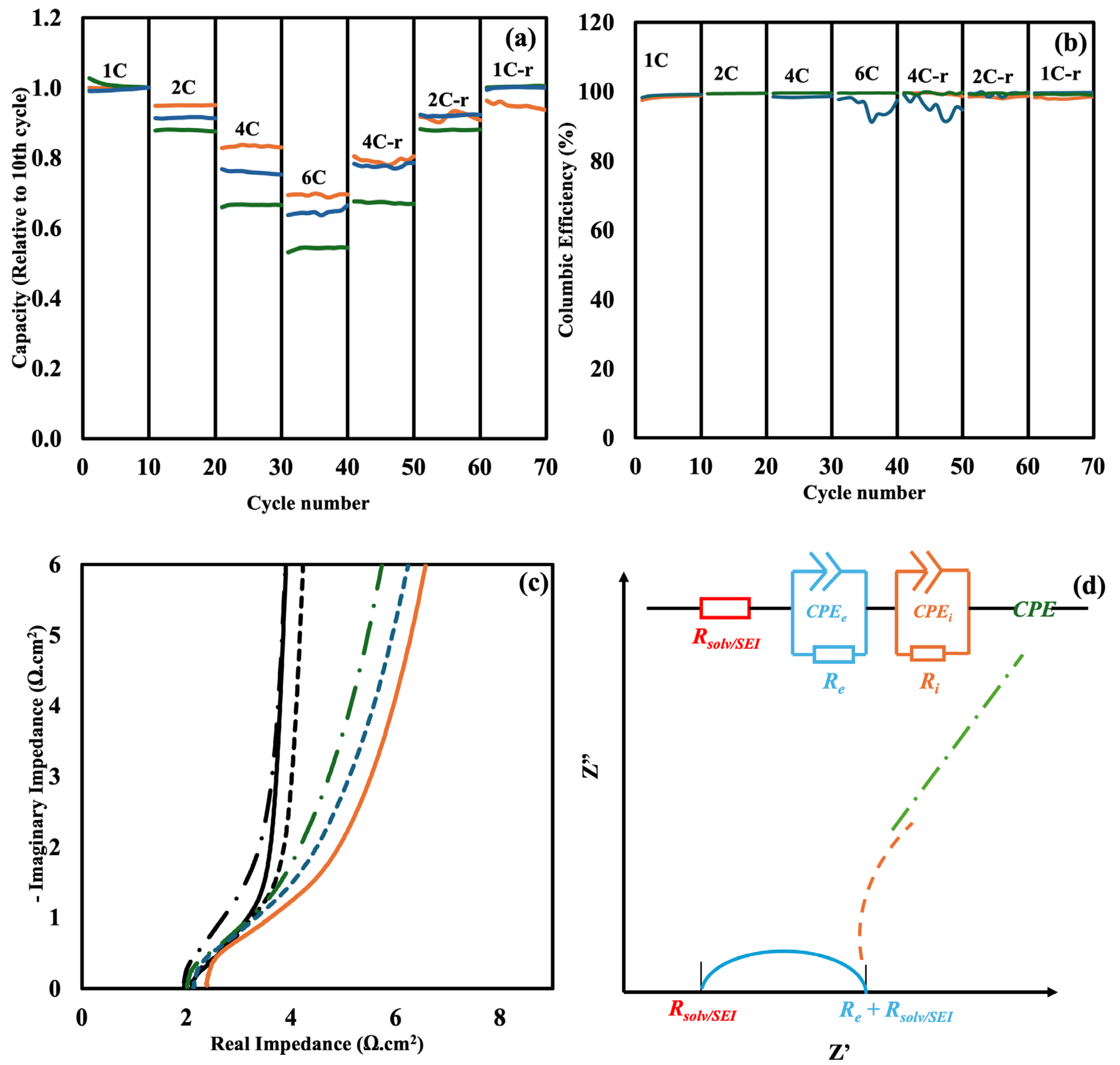
Figure 2a and
Figure S1 provide details about the cycle rate of control LiPF
6, NaPF
6-added sample, and 0.02 M KPF
6 additives half cells with the formation of SEI at 0.1 C (
Figure 2a) and 1 C (
Figure S1) over various C-rates. The capacity is normalized to the 10th cycle. It can be seen from
Figure 2a that, when the SEI is formed at 0.1 C, the control cell with LiPF
6 shows a superior performance in terms of capacity across various C-rates, especially at 4 C and 6 C. The SEI formed in samples with NaPF
6 and KPF
6 additives exhibits higher resistance. However,
Figure S1 reveals that this resistance is eliminated when the SEI is formed at 1 C. The stability of the cells is also improved when they return to lower C-rates when NaPF
6 and KPF
6 are added to the electrolyte (4 C-r, 2 C-r, and 1 C-r). The Coulombic efficiency for the three electrolytes during 70 cycles at different C-rates is shown in
Figure 2b. Throughout the experiment, every cell maintained a high Coulombic efficiency, remaining above 99%, which suggests robust cycling performance and little adverse effects. Nevertheless, during the high-rate 6 C cycle and the ensuing 4C-return phase, the cell with 0.02 M KPF
6 additive displayed a discernible decrease in Coulombic efficiency, most likely as a result of enhanced polarization or unstable SEI behavior at high current densities. The efficiency notably improved in the later phases, indicating that the SEI created under high-rate cycling conditions somewhat stabilized.
Figure 2c represents the EIS data for cells with and without SEI formed at 0.1 C. The equivalent circuit model R
1 + (Q
2‖R
2) + (Q
3‖R
3) + Q
4 that was utilized to fit the EIS data is shown in
Figure 2d. A fitted graph has been plotted in
Figure S4 in the SI, and the parameters of the fitting have been summarized in
Table S1. R
1 represents ion impedance in the solvent, Q
2/R
2 represents the electronic interface and is fitted to the high frequency part of the elongated semi-circle, while Q
3/R
3 represents the ion interface and is fitted to the lower frequency part of the semi-circle. Constant phase element Q
4 represents the overall capacitance of these symmetric capacitor test cells. Among the samples with SEI formed at 0.1 C, the control sample with 1.22 M LiPF
6 shows the highest solution impedance (R
1) (2.41 Ω·cm
2). However, the cell with 1 M LiPF
6 and 0.22 M NaPF
6 shows the lowest impedance in the low to mid impedance range (2.01 Ω·cm
2). This suggests that the addition of NaPF
6 enhances the SEI formation. However, the sample with 1.22 M LiPF
6 and 0.02 M KPF
6 shows slightly higher impedance (2.13 Ω·cm
2) compared to the NaPF
6 added sample. The ionic conductivity of the electrolytes was barely affected by the addition of NaPF
6 and KPF
6 additives, as shown by the impedance spectra of samples without SEI formation in
Figure 2c. In the case of the control electrolyte with LiPF
6, the extracted solution resistance (Rs) values were 2.10 Ω·cm
2, 1.94 Ω·cm
2 for the electrolyte that had NaPF
6 added, and 2.09 Ω·cm
2 for the electrolyte that had KPF
6 added. These slight variations—within around ±4%—indicate that the enhancements in electrochemical performance are caused mainly by these additives’ effects on SEI characteristics, rather than modifications in ionic conductivity. The ion interface level (Q
3 and R
3) showed notable changes, confirming the claim that SEI formation alters this area in particular. With values more than doubling in the case of LiPF
6, R
3 shows a significant rise. This rise is in line with the extra ionic transport resistance at the interface caused by a resistive SEI layer. The electrochemical signature of SEI formation—a more resistive, less capacitive interface, which is a feature of passivating SEI films—is further supported by the notable decrease in Q
3 and the rise in R
3.
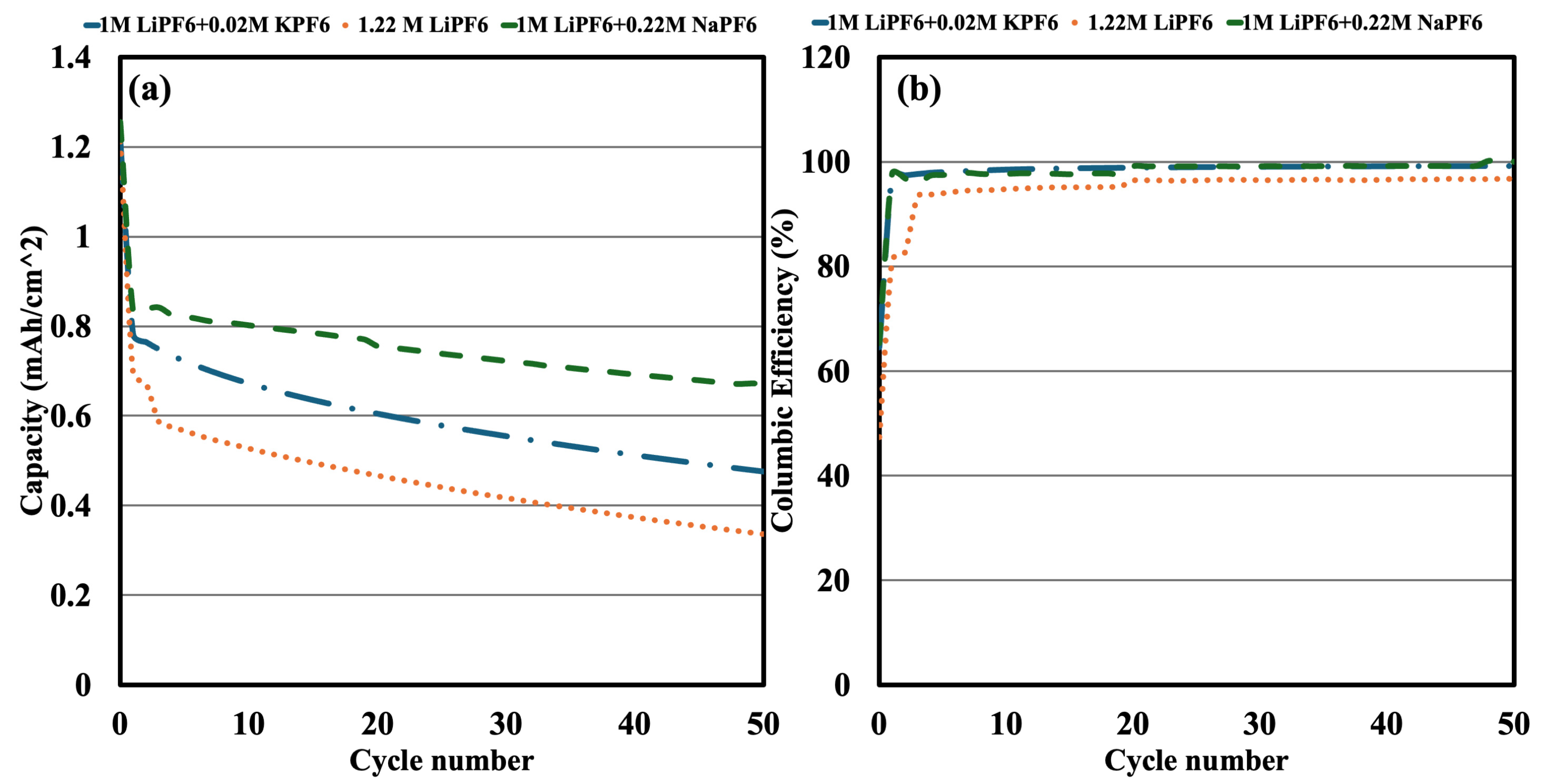
Using the same electrolyte compositions, full cells were assembled and cycled for 50 cycles at 0.5 C between 2.6 V and 3.6 V, after the electrolyte effects were confirmed in half-cell experiments (
Figure 3a). Although LFP had an initial loading of 1.25 mAh/cm
2, different electrolytes had different measured capacities, following SEI formation because of differing levels of irreversible capacity loss (ICL). According to
Figure 3a, after SEI formation, the capacity decreased to 0.69 mAh/cm
2, and the 1.22 M LiPF
6 electrolyte showed the highest ICL (44.8%). By comparison, the electrolyte containing 1 M LiPF
6 + 0.22 M NaPF
6 had the lowest ICL (33.6%) and retained 0.83 mAh/cm
2, whereas the electrolyte containing 1 M LiPF
6 + 0.02 M KPF
6 had an intermediate ICL (37.6%) and a capacity of 0.78 mAh/cm
2.
The trends in capacity retention further deviated over the first 50 cycles. By the 50th cycle, the LiPF
6 electrolyte’s capacity had dropped to 0.32 mAh/cm
2, indicating severe degradation. On the other hand, the electrolyte containing KPF
6 demonstrated a moderate capacity retention of 0.47 mAh/cm
2, whereas the electrolyte with NaPF
6 maintained the maximum capacity at 0.67 mAh/cm
2. According to these findings, NaPF
6 and KPF
6 improve long-term cycling performance by reducing irreversible capacity loss and SEI formation. Our previous half-cell results, which showed that NaPF
6 and KPF
6 affected SEI composition and interfacial stability, are consistent with the full-cell data. Lower capacity retention and higher lithium consumption are the outcomes of the baseline LiPF
6 electrolyte’s facilitation of larger SEI formation. Compared to LiPF
6, KPF
6 reduces initial capacity loss; nevertheless, it is less effective over the long term than NaPF
6. In addition to the capacity data in
Figure 3a,
Figure 3b shows the Coulombic efficiency of the full cells across 50 cycles. With values remaining close to 99% during the cycle, all three electrolyte systems demonstrated continuously high Coulombic efficiency, indicating low parasitic reactions and good reversibility of the charge-discharge processes in all formulations. Additional tests were carried out utilizing sophisticated electrodes that could generate SEI at greater current densities in order to confirm the effectiveness of the NaPF
6 and KPF
6 additives. These studies demonstrate that, under both 1 C and 0.1 C SEI formation circumstances, NaPF
6 consistently provides improved capacity retention when compared to the baseline and KPF
6-containing electrolytes, as illustrated in
Figure S3a,b in the Supplementary Information. Interestingly, under 1 C formation circumstances, NaPF
6 inhibited lithium plating, whereas the baseline electrolyte showed early indications of plating. These results support NaPF
6′s ability to stabilize SEI and improve long-term cycling performance, particularly when fast-formation methods and high-conductivity electrode designs are used.
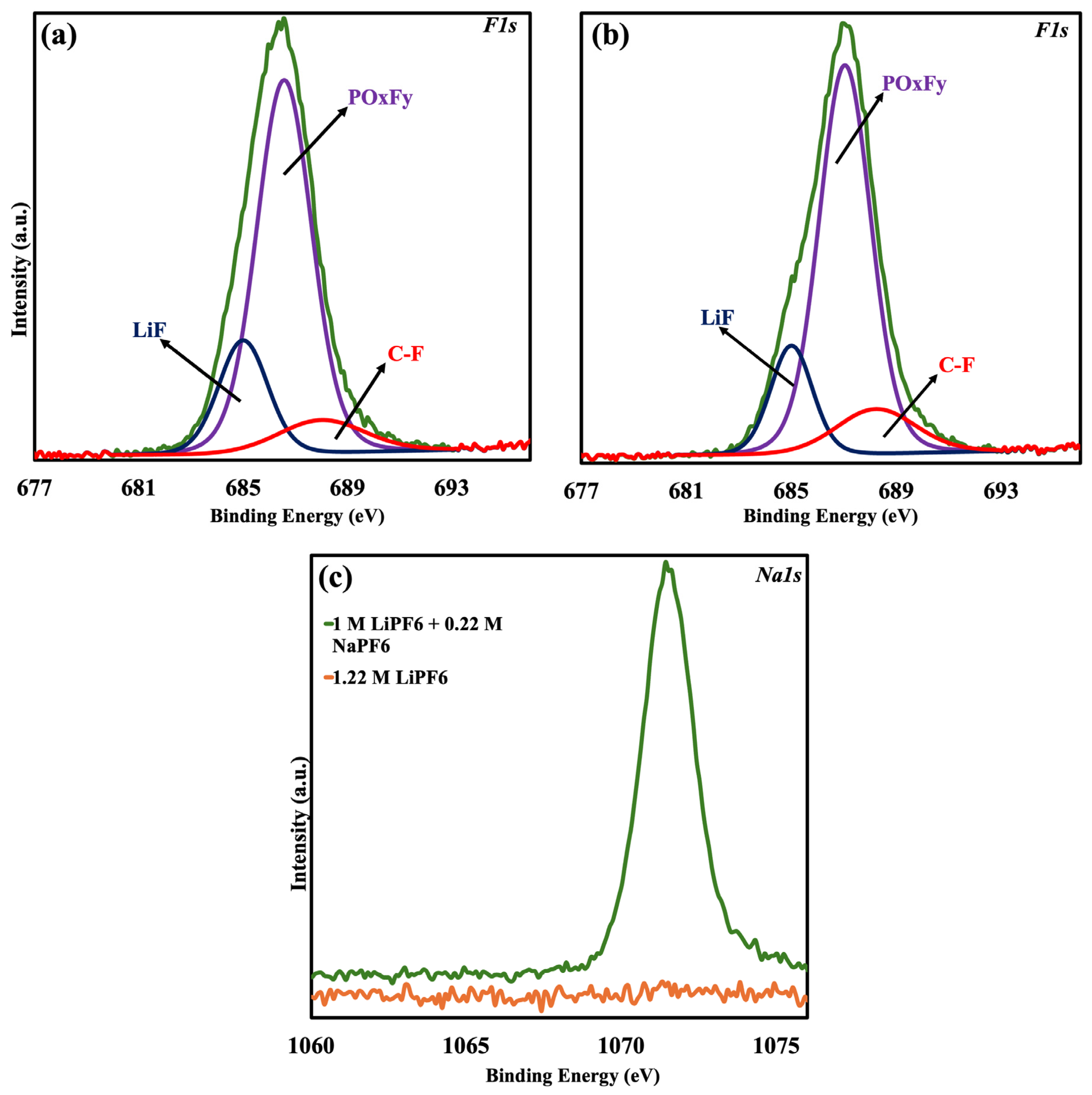
XPS was performed on the graphite anodes to examine the surface chemistry of the solid electrolyte interphase (SEI) that forms in various electrolyte systems. The presence and impact of Na and K in the SEI were verified by high-resolution scans for Na 1s, F 1s, Li 1s, and C 1s on three separate samples. The Na 1s scan (
Figure 4c) was employed to verify sodium incorporation in the SEI for the NaPF6-containing electrolyte (sample 2). Successful sodium incorporation was demonstrated when NaPF6 was added to the electrolyte, since sample 2 had a noticeable Na peak at 1072 eV, whereas the control sample (1.22 M LiPF6) did not exhibit it.
High-resolution F 1s, Li 1s, and C 1s scans were performed on sample 1 (control) and sample 4 (1 M LiPF
6 + 0.02 M KPF
6) in order to assess the role of Potassium in SEI formation.
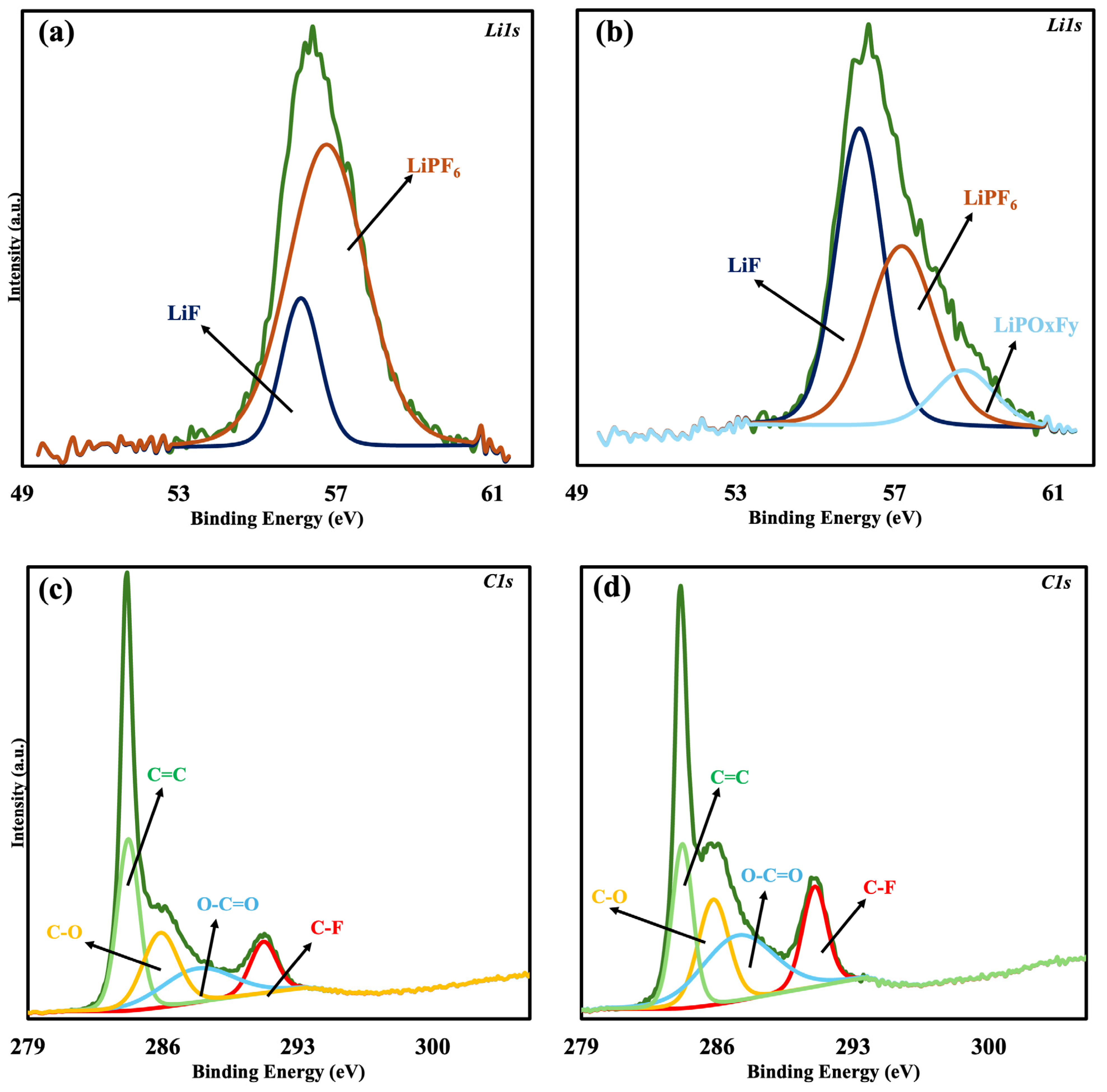
Figure 4a,b show the F 1s spectrum for samples 1 and 4. The C-F bond contribution increased from 10.09% in the control sample to 12.79% in sample 4, indicating that K affects surface species associated with fluorine. Additionally, the Li 1s spectrum, which is depicted in
Figure 5a,b, provides additional evidence that K promotes LiF formation in the SEI by demonstrating a notable rise in LiF content, which increased from 19.78% in the control sample to 47.61% in sample 4. The observed trend in F 1s was further supported by the C 1s spectra (
Figure 5c,d), which likewise show an increase in C-F bonding, going from 10.84% in the control sample to 15.35% in sample 4. These findings align with the previous literature that suggests K
+ may not exist as free K-containing species but instead contribute mainly to the production of LiF and C-F bonds [
31,
32].


