1. Introduction
Surface Air-Cooled Oil Coolers (SACOCs), also known as surface air-oil heat exchangers (SAOHE), can become an essential part of the thermal management of turbofan engines, which are increasingly experiencing increased thermal loads due to advances. Sources of additional heat can be gearboxes in geared fan engines like Rolls-Royce UltraFan [
1] or increased electrical systems requirements. In the first case, increasing the bypass ratio requires the use of a gearbox that adjusts the rotation speed of the fan, which is limited by its increased outer diameter with the rotation speed of the turbine. In the other case, replacing mechanical controllers as well as hydraulic actuators with fly-by-wire systems, as well as a general increase in the number of electrical systems that replace the work of the pilots, results in more heat being dissipated. This causes the capabilities of conventional heat sinks to be insufficient.
SACOCs can be located on the wall of the turbofan engine bypass duct, where they use the high-mass flow stream of air as an effective heat dissipation medium. The potential integration of SACOCs in modern aeroengine designs is based on their ability to simplify oil cooling under rigorous operational conditions, which supports improved lubrication, thermal management, and overall engine reliability. It is important to mention that their implementation introduces aerodynamic challenges like pressure drop and flow distortion, which can affect engine performance. Therefore, a complex aerodynamic and thermal analysis is necessary to optimize their design and integration.
Engine oil serves the dual function of lubricating and cooling, by transferring heat absorbed from bearings and gears to the fuel through Fuel-Oil Heat Exchangers (FOHEs). This method uses the ability of the fuel to act as a heat sink before combustion, which increases the thermal efficiency. However, this method has limitations. The mass flow of the fuel changes during flight, resulting in an irregular heat absorption capacity. Furthermore, accurate regulation of fuel temperature is required to avoid issues such as coking, which can cause damage to engine components or lead to unstable work of fuel injectors. In addition, the increasing application of composite materials in aircraft structures, characterized by lower thermal conductivity compared to traditional alloys, undermines the efficacy of the airframe in dissipating heat [
2,
3].
Surface Air-Cooled Oil Coolers (SACOCs) represent an innovative approach to dealing with high thermal loads. These devices are conventionally positioned within the engine’s bypass duct, where they use bypass flow as an effective heat sink, making it easier to transfer heat from the engine oil. This configuration reduces the dependence on fuel as the primary heat sink while simultaneously using existing airflow, thus reducing the need for additional cooling systems. However, integration of SACOCs poses aerodynamic challenges, including potential pressure drops and flow distortions, which can affect engine efficiency. Consequently, the accurate design and optimization of the SACOC geometry is mandatory to achieve a balance between efficient thermal management and minimal aerodynamic losses [
2,
4,
5].
2. Function and Integration of SACOCs in Turbofan Engines
2.1. SACOC Working Principle and Structure
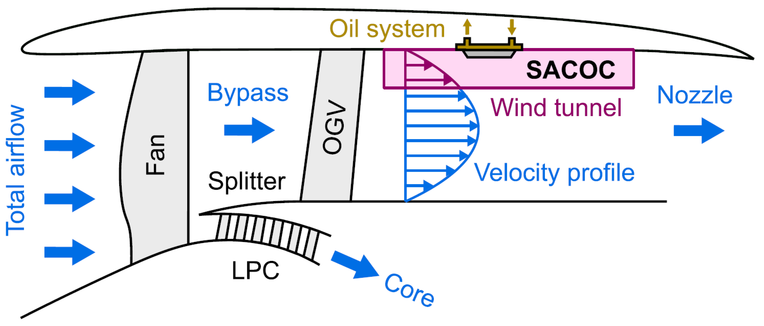
Surface Air-Cooled Oil Coolers (SACOCs) are based on convective heat transfer. Hot oil flows internally through channels in a finned block while the cooler bypass air flows around the external surface, absorbing thermal energy. SACOCs can be installed along the inner wall of the bypass duct (
Figure 1), thus taking advantage of the high mass flow and relatively low temperature of the bypass air, even under high thrust conditions [
2].
In the further examples discussed below, SACOCs are proposed to take the shape of an array of fins, pin fins, strip fins, or microchannel structures, having oil tubes inside, which serve to increase the surface area and thus increase the rate of heat transfer [
6,
7]. These solutions require an equilibrium between thermal effectiveness and aerodynamic performance to prevent significant pressure drop or flow distortion [
2,
5]. Given the high-velocity characteristics of the external air flow, often high Mach number, proper fin geometry design, surface roughness, and material selection are required. [
8].
2.2. Placement in the Bypass Duct
The placement of SACOCs within the bypass duct in the bypass duct provides a continuous high-mass flow of relatively cool air, which is ideal for convective heat rejection. Unlike the core flow, which is highly energetic and contains combustion products, the bypass flow remains cleaner and more thermally stable, making it more suitable as a heat sink for sensitive cooling applications [
4]. Additionally, the geometry of the bypass duct geometry allows for the installation of heat exchangers without increasing the frontal area of the engine or requiring additional ducting [
5], which is possible due to the low height and compact geometry. The curved inner wall of the bypass duct provides a large surface area for SACOC integration, and its proximity to the fan and low-pressure compressor stages ensures airflow in all operating conditions, including low-speed ground operations and take-off [
9].
2.3. Integration Challenges: Aerodynamic Penalties and Thermal Efficiency Trade-Offs
Maximizing the heat transfer rate requires increasing the wetted surface area, which leads to higher viscous drag and pressure drop in the bypass stream [
10]. Such pressure losses can affect engine efficiency, especially in high-speed flows where Mach numbers in the bypass duct approach 0.5 or higher [
8]. Furthermore, inappropriate and incompatible with flow parameters, SACOC geometries can introduce flow separation, shock wave interaction, or secondary vortices that distort bypass flow, potentially affecting downstream components and reducing engine performance [
11]. To mitigate these aerodynamic losses, designers must carefully tune the density, orientation, and surface roughness of the fin to balance heat dissipation with acceptable drag levels. This is challenging because improvements in thermal performance, such as more aggressive fin profiles, often worsen pressure loss, requiring iterative design and optimization informed by both Computational Fluid Dynamics (CFD) and wind tunnel testing [
6,
12]. When reducing pressure losses and flow distortion, it should not be forgotten that for turbulent flow, heat transfer coefficient
h depends on the velocity
v and air density
as follows:
This means that pressure losses and distortion of the velocity profile are detrimental to both engine efficiency and the efficiency of SACOCs themselves.
2.4. The Meredith Effect and Performance Recovery
Broatcch et al. [
13] suggest that SACOCs can benefit energy conversion through the phenomenon called the Meredith effect, where heated bypass air expands and produces additional thrust in the secondary nozzle. This can make the bypass duct not only a practical location from a thermal point of view but also a contributor to overall propulsive efficiency, which will be analyzed in a later section.
This effect was first described in 1936, by British engineer Frederick William Meredith in his “Cooling of Aircraft Engines. With Special Reference To Ethylene Glycol Radiators Enclosed In Ducts” report [
14]. Meredith’s work demonstrated that by designing the cooling ducts to allow heated air from the radiator to exit at high velocity, it was possible to generate forward thrust, partially offsetting the drag caused by the radiator itself. More specifically, increasing the air enthalpy before it exits through the secondary nozzle can lead to partial compensation for the drag introduced by the heat exchanger.
The effectiveness of this mechanism depends on multiple factors, including the placement of the heat exchanger, the air pressure and velocity in the bypass duct, and the degree of increase in temperature imparted to the air [
11]. Although the Meredith effect was originally exploited in piston-engine aircraft of the WWII era, its relevance in turbofan applications has grown with the increasing thermal loads and compact engine architectures that demand localized heat rejection solutions [
15]. Modern SACOC designs can be optimized not only for minimal pressure drop and maximum heat dissipation, but also to maximize the thrust benefit derived from bypass air heating, effectively turning a cooling requirement into a performance enhancement opportunity [
6].
However, due to the lack of reliable data, it is difficult to calculate the level of thrust recovered from heat for a real engine. Anyway, based on the known Rolls-Royce UltraFan 800 geared turbofan engine, with a bypass ratio 14:1, 360 kN of thrust, and 64 MW of fan power, and adding assumptions such as bypass mass flow = 882 kg/s (hypothetical, ideal, based on thust and bypass ratio), almost exactly 1 N of thrust will be received. Such a low propulsion efficiency of such a system is obviously due to insufficient compression for optimal Brayton Cycle usage.
3. Aerothermal Characterization of SACOCs
3.1. Experimental Techniques for SACOC Testing
Experimental evaluation plays a crucial role in the development and validation of SACOC designs, especially given the complexity of flow and thermal interactions within the bypass duct environment. Due to the costs and logistical difficulty of full-scale engine testing, scaled-down SACOC prototypes are mostly used in transonic wind tunnels that can replicate the flow conditions found in engine bypass ducts. The test section used in the study by Broatch et al. [
2] replicates a part of the bypass duct, as shown in
Figure 1. These facilities allow researchers to analyze heat transfer rates, pressure drop, and flow distortion under controlled and repeatable conditions.
To look deeper into flow velocity field and aerodynamic losses, non-intrusive optical diagnostics, such as Particle Image Velocimetry (PIV) and Schlieren imaging, can be used, offering high-resolution visualization and shock interactions near the SACOC surfaces [
13]. Advances in Additive Manufacturing make possible complex SACOC geometries, including internal fin structures and conformal duct surfaces that would be difficult or impossible to fabricate using traditional machining methods. This leads to the acceleration of the design iteration cycles and allows researchers to explore new shapes of the heat exchangers and internal channel topologies [
16].
3.2. Numerical Simulations and Validation Approaches
Numerical simulation has become an important tool in the aerothermal development of SACOCs, enabling the detailed exploration of complex flow and heat transfer phenomena that are difficult, too expensive, or impossible to capture experimentally. Computational Fluid Dynamics (CFD) allows for the visualization of local temperature gradients, flow separation zones, and turbulent structures around and inside the SACOC geometry, providing an overview of performance limiting factors such as hot spots or excessive pressure drops, especially those that are impossible to measure directly during an experiment [
7]. Reynolds-Averaged Navier–Stokes (RANS) [
17] and Large Eddy Simulation (LES) [
18] models are used depending on the desired level of detail and computational cost. Conjugate Heat Transfer (CHT) [
19] simulations are often used to capture the simultaneous interaction between solid fins and fluids, typically oil inside and air outside, allowing for accurate heat flux predictions [
6]. The validation of numerical results should be carried out via comparison with experimental data, using surface temperature distributions, outlet air temperatures, and pressure profiles [
5]. Recent studies have combined CFD with parametric optimization algorithms to explore the effect of fin geometry, pitch, and orientation on both thermal and aerodynamic performance, improving design based on multiple design variables [
12].
3.3. Representative Studies
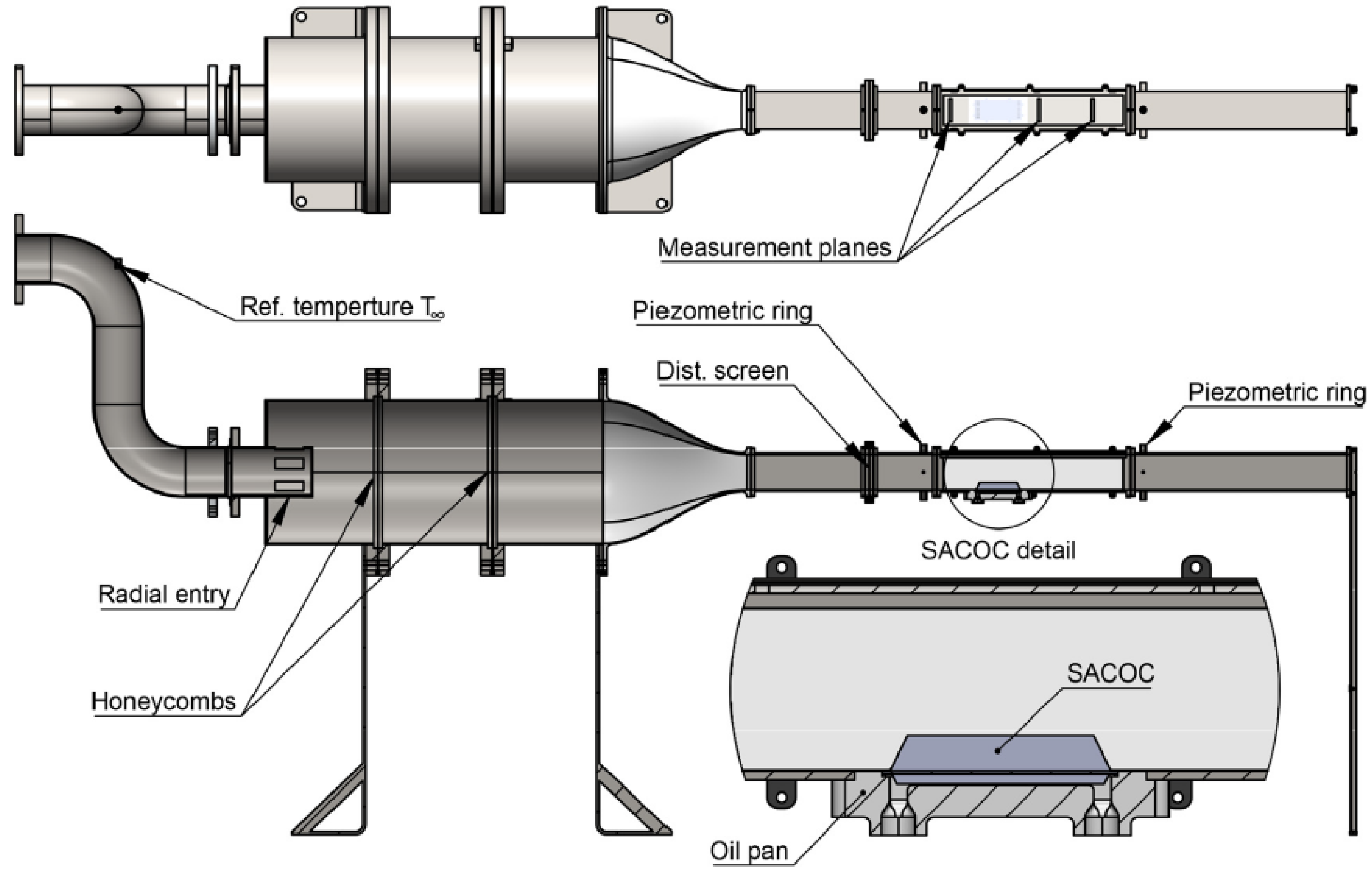
The biggest impact on understanding SACOC performance was achieved by integrating experimental, numerical, and optimization methodologies. The studies mentioned above, performed by Broatch et al. [
2], conducted experimental investigations in transonic wind tunnels to characterize the aerodynamic and thermal performance of SACOCs under realistic bypass conditions, where the SACOCs were placed in a tunnel channel in which the velocity field corresponding to the actual bypass flow was created by the distorting screen (
Figure 2). Based on this, the same authors examined the effect of rounded fin geometries [
12], highlighting how minor changes in cross-sectional curvature could improve heat transfer efficiency and decrease aerodynamic drag. Then, in 2024, the same research group introduced the use of optical measurement techniques and Additive Manufacturing to improve prototyping and achieve high-resolution flow diagnostics, allowing for rapid iteration in early design phases [
13]. Parallel to these investigations, Chávez-Modena et al. [
6] developed a numerical framework for fin shape optimization using CHT simulations, allowing for detailed sensitivity analyses of geometric parameters. Their work also lead to experimental experimental validation in 2023, confirming its precision and suitability to guide the design of the SACOC [
5], where the CFD error relative to the experiment did not exceed 3.1% for pressure drop and 1.2% for heat transfer. Together, these studies form a set of work that addresses both fundamental mechanisms and practical design trade-offs in the integration of SACOCs. More case-specific studies will be presented in the following sections about optimization and high-speed flows.
4. Fin Geometry and Design Optimization
4.1. Influence of Fin Geometry on Pressure Drop, Heat Transfer, and Flow Uniformity
The performance of SACOCs has critically influenced how pin geometries affect pressure drop, heat transfer rates, and flow uniformity across the heat exchanger surface. High-performance fins promote turbulence and disrupt boundary layers, increasing convective heat transfer. However, these same features often result in increased friction losses and non-uniform velocity distributions, leading to higher-pressure drop penalties. Jeng and Tzeng [
20] showed that staggered pin-fin arrays provide better heat transfer performance than in-line configurations but at the cost of significantly greater pressure loss. For example, for Reynolds Number 12,500, a staggered array of square pin-fins can reach 20% better heat transfer than in-line circular fins but also 25% greater losses.
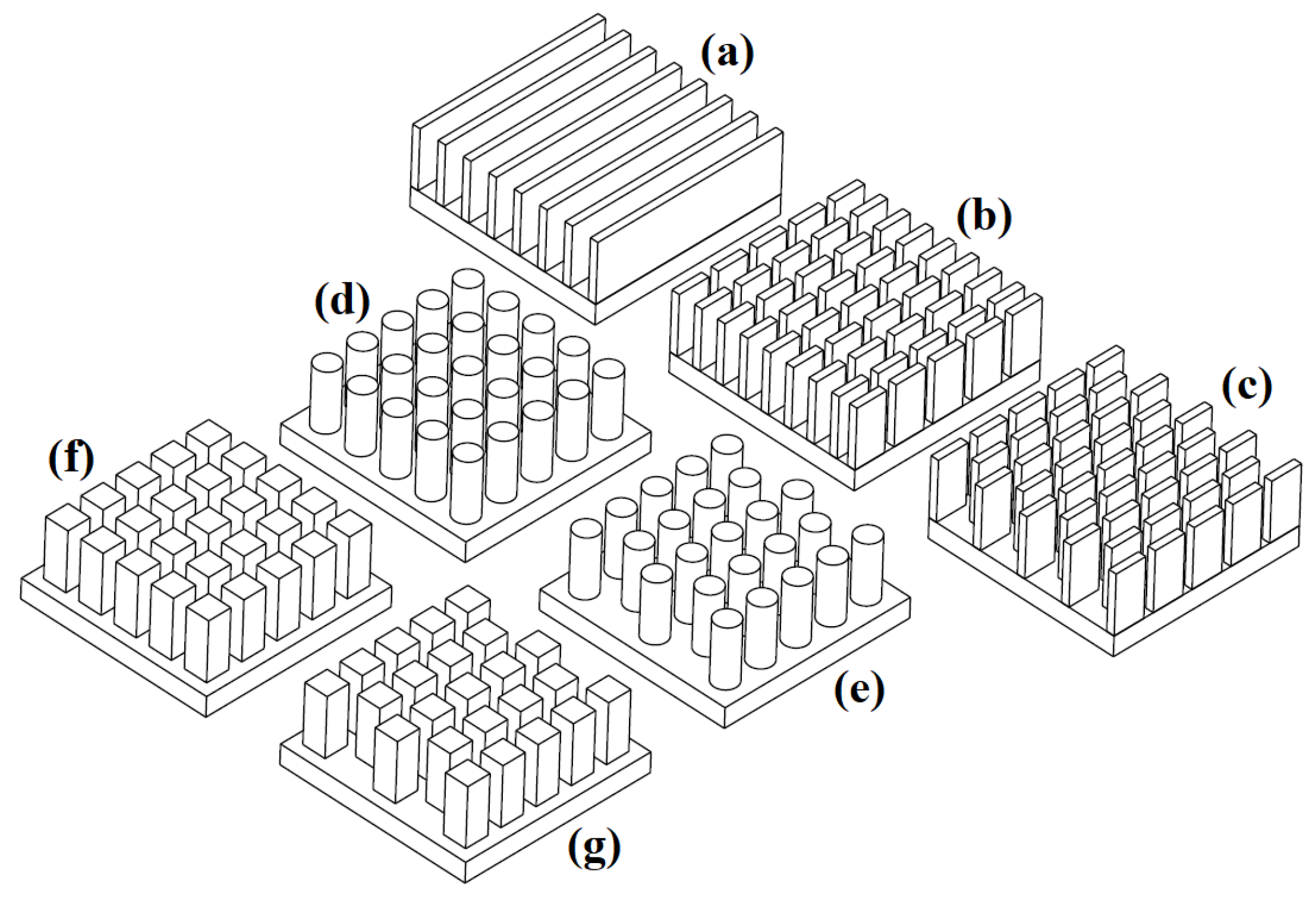
Similarly, Jonsson and Moshfegh [
21] demonstrated that bypass of the flow that outflows the finned core can reduce both the thermal effectiveness and the predictability of flow patterns in plate-fin and pin-fin heat sinks. Importantly, the authors point out that diversities in temperature and velocity fields also increase local thermal stresses on fins, which can impact mechanical durability over time. Experiments and calculations are carried out for different pin shapes (
Figure 3) and for Reynolds Numbers in the range 2500 to 15,000. Numerical simulation has become an important tool in the aerothermal development of SACOCs, enabling the detailed exploration of complex flow and heat transfer that are difficult, too expensive, or impossible to capture experimentally.
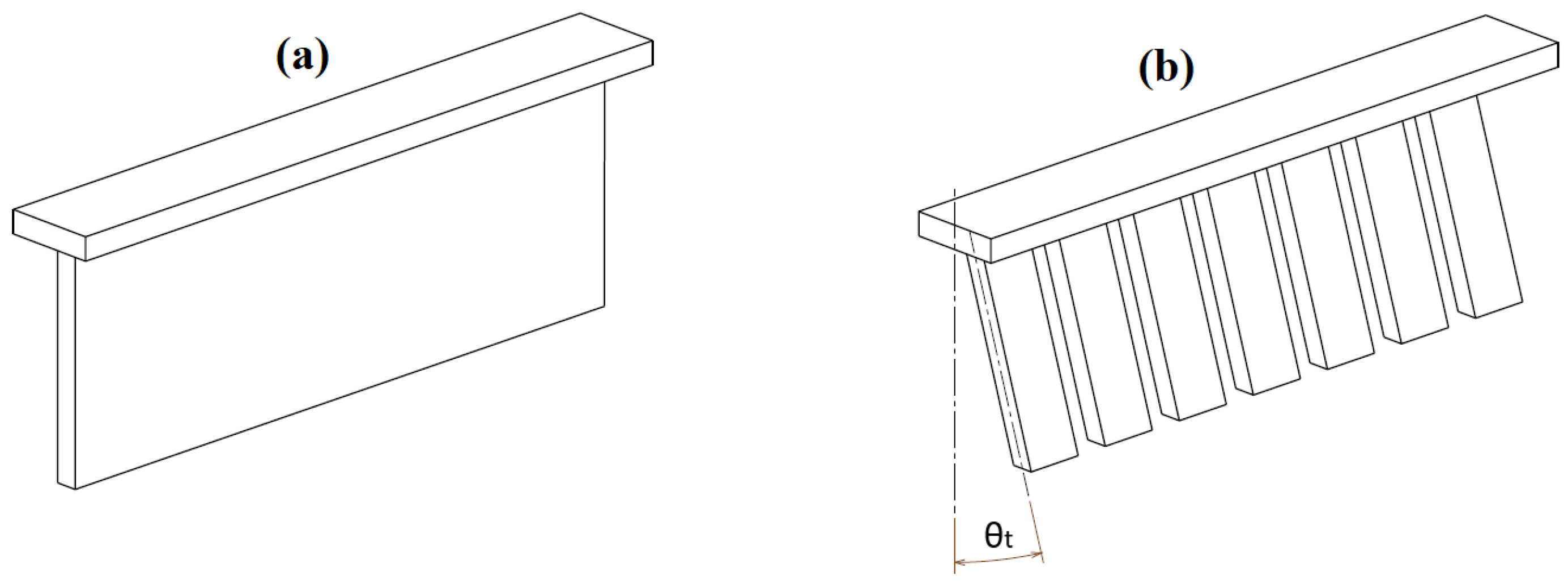
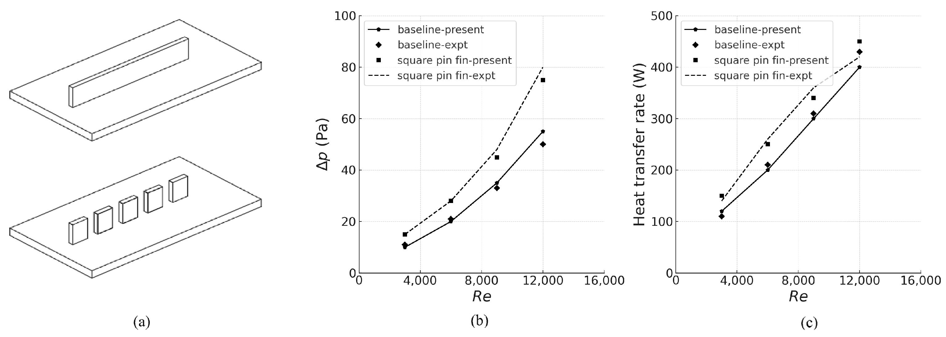
The study by M.Kim et al. [
7,
10] explored the aerothermal behavior of the slanted pin fin arrangements, such as the plate fin and the slanted fins for four different angles (
Figure 4), as well as different fin heights and Reynolds Numbers, for their ability to enhance convective heat transfer while minimizing aerodynamic losses. The first flat plate fin and pin fin comparison showed an increase in pressure losses of 27% and an increase of 12.5% in heat transfer for square pin fins in Reynolds Number 12,000 (graph in
Figure 5).
The slant angle influences flow, resulting in certain increases in heat transfer as well as in an increase in pressure losses, but the studies are confusing because the results for different slant angles do not show clear patterns, as well as results in diagrams (b) and (c) in
Figure 5 show fewer differences than declared accuracy (3.2% for pressure drop). In addition, the inaccuracy between CFD and experiment is 9% for aerodynamics and 7.5% for heat transfer. In addition, the results are shown for different Reynolds numbers, where the fin height is given as the characteristic dimension, which varies from case to case. Moreover, the Reynolds Numbers chosen for the study appear to be too low for the bypass channel of the turbofan engine. Additionally, S.Kim et al. [
4] showed that the interaction between bypass flow and SACOC geometry is related not only to the drag profile but also the internal oil-side temperature distribution, affecting the uniformity and predictability of thermal performance. These findings emphasize that SACOC performance cannot be evaluated under low-speed assumptions and must instead account for the complex aero thermal coupling that arises in high-speed bypass conditions.
4.2. Optimization Techniques and Design Trade-Offs
Designing SACOC fins involves a multi-objective optimization process that balances heat transfer enhancement and aerodynamic performance. Traditional trial-and-error methods, as mentioned above in research, have been increasingly replaced by computational optimization techniques, including genetic algorithms [
22], response surface models, and adjoint-based solvers [
23]. These methods allow designers to evaluate large parametric spaces efficiently, identifying optimal configurations. Guo et al. [
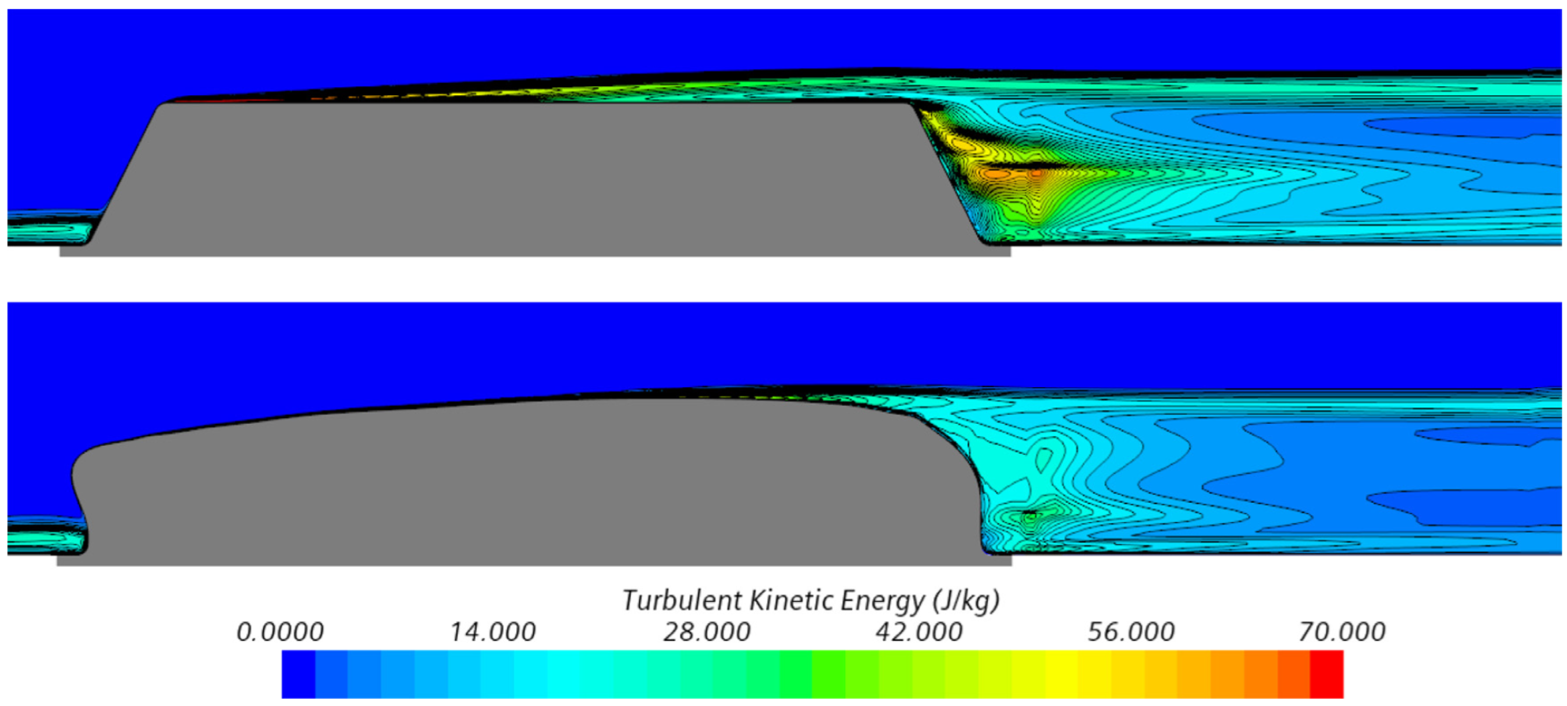
24] demonstrated an example of using a structured optimization for the geometry of counterflow plate-fin heat exchangers, achieving notable improvements. Similarly, as mentioned above, Chávez-Modena et al. [
6] applied a simulation-based Conjugate Heat Transfer (CHT) approach to optimize fin geometry and spacing under bypass duct conditions. These optimizations often reveal nonintuitive design choices, such as asymmetrical fin layouts or nonuniform spacing, that can be better than traditional symmetric configurations. The example of results can be seen in
Figure 6, which shows a noticeable decrease in turbulent kinetic energy for optimized fin shape. The new geometry results in a significant decrease in pressure drop of 10.6%, while the change in heat transfer is minimal (around 0.3 %). However, performance gains must be carefully weighed against complexity and manufacturing constraints, especially if they are related to internal oil pipes.
5. High-Speed Flow Effects and Aerodynamic Interactions
5.1. Impact of Transonic and High Bypass Flows on SACOC Performance
In modern engines, bypass Mach Number can exceed 0.5 during cruise and take-off, placing SACOCs in a transonic or even locally supersonic regime. These conditions fundamentally alter the flow structure on the heat exchanger surface, increasing the complexity of pressure recovery, turbulence generation, and boundary layer behavior. Sousa et al. [
11] demonstrated that transonic effects lead to localized shock formation and unsteady flow separation on the fin surfaces, which can significantly impact thermal effectiveness and introduce dynamic loads that degrade structural integrity over time. These studies were also one of the best representations of the actual geometries of the bypass channel and flow conditions. The cooling demands are indicated to be the highest in take-off conditions and a heat exchanger sensitivity less than 10% for the flight envelope. Continuing research in similar channel geometry and Mach Number 0.8, Villafañe and Paniagua [
8] performed tests for “continuous fins” and “interrupted fins”, which are smilar geometries to Plate fin and square Pin-Fins tested by M.Kim et al. [
7]. It was noted that interrupted fins generate greater flow distortion than perturbations in the case of continuous fins.
5.2. Flow Distortion, Pressure Losses, and Mitigation Strategies
The bypass air interacts with the SACOC surfaces and densely packed or high-profile fins, which can lead to flow separation, vortex shedding, turbulence intensification, and non-uniform outlet velocity profiles. These effects are even more important when approaching transonic flow. Rebassa et al. [
25] quantified these distortions using a high-speed wind tunnel, for Mach Number 0.3 to compare with previous studies and Mach Number 0.5 as closer to bypass duct conditions. The tests were performed for finned geometries, similar to those designed by Modena et al. [
6] (
Figure 6). Unfortunately, the article lacks numerical results for Mach 0.5, making a comparative evaluation impossible.
In parallel, studies mentioned above by Villafañe and Paniagua [
8] showed a transonic wind tunnel experiment for Mach Number of approximately 0.8. In this case, the geometries tested were similar to those tested by M. Kim et al. [
10]. Again, it is difficult to make a comparison, since both the flow parameters and geometric dimensions were completely different. However, it should be mentioned that these were the first tests in which the wind tunnel channel reproduced the actual curvature of the bypass duct wall.
6. Advanced Heat Exchanger Concepts for Aero Engines
6.1. Cooled Cooling Air (CCA) and Precooled Engine Technologies
Advanced cooling strategies such as Cooled Cooling Air (CCA) systems and pre-cooled engine cycles are gaining prominence. CCA technology involves preconditioning the cooling air, typically by expanding or cooling it before it reaches heat exchangers, thus enhancing its capacity to absorb heat from lubricating oil or other thermal sources. C. Kim et al. [
26] developed and experimentally validated a compact CCA heat exchanger, demonstrating significant improvements in heat transfer performance and structural durability under representative engine conditions. Similarly, Zhuang et al. [
27] conducted an analysis of CCA for low bypass ratio engines, showing it to be an alternative to conventional oil or fuel-based heat sinks. In parallel, pre-cooled engine concepts, borrowed from hypersonic propulsion, use regenerative heat exchangers to cool the air that enters before compression. Wang et al. [
28] modeled the performance of such systems for intake precooling in hypersonic engines, revealing potential thrust and fuel efficiency.
6.2. New Materials and Manufacturing Methods (e.g., SLM)
Advancements in materials and manufacturing technologies enable novel geometries, improved thermal performance, and enhanced mechanical resilience. One of the most transformative developments is the use of Selective Laser Melting (SLM), also known as Selective Laser Sintering (SLS), and other Additive Manufacturing (AM) techniques, which allow for the fabrication of intricate, high-performance heat exchanger structures that were previously unachievable using traditional subtractive methods. Wong et al. [
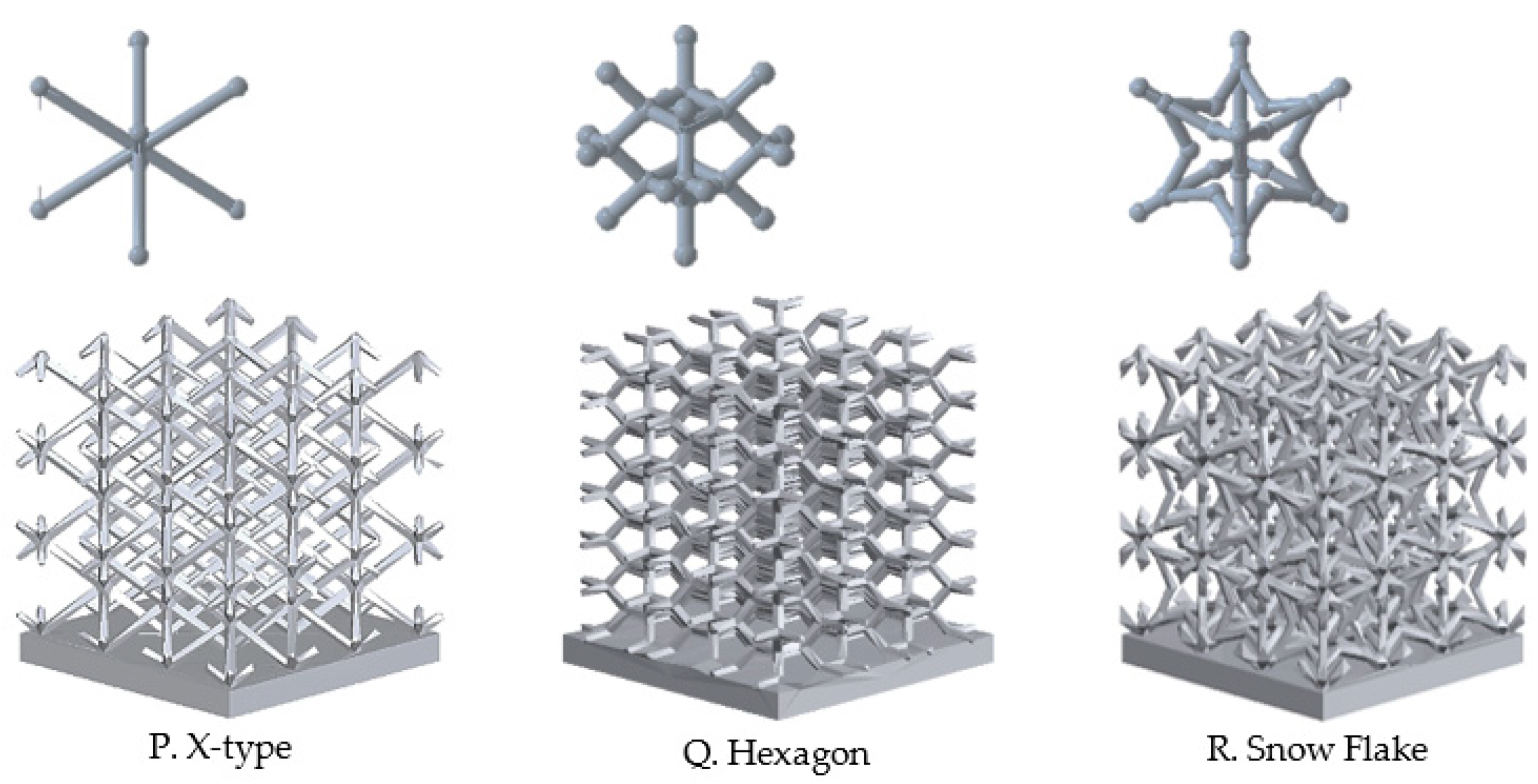
16] demonstrated that SLM-produced heat sinks could achieve complex internal geometries with high dimensional accuracy, resulting in both improved convective heat transfer and reduced pressure losses compared to their conventionally machined counterparts. Another paper by Silva et al. [
29] presents an interesting analysis of various heat sinks, one of which, shown in
Figure 7, is a great example of a geometry that is impossible to mill or cast (due to thin walls) but is an excellent demonstrator of SLM technology.
Furthermore, AM supports the integration of graded materials and controlled porosity, which can be used to locally optimize thermal conductivity and mechanical strength [
30]. In parallel, new high-temperature alloys and composite–metal hybrids are being investigated to withstand thermo-mechanical environments inside bypass ducts.
7. Future Challenges and Research Directions
7.1. Integration with Next-Gen Propulsion (Hybrid-Electric, Ultra-High Bypass)
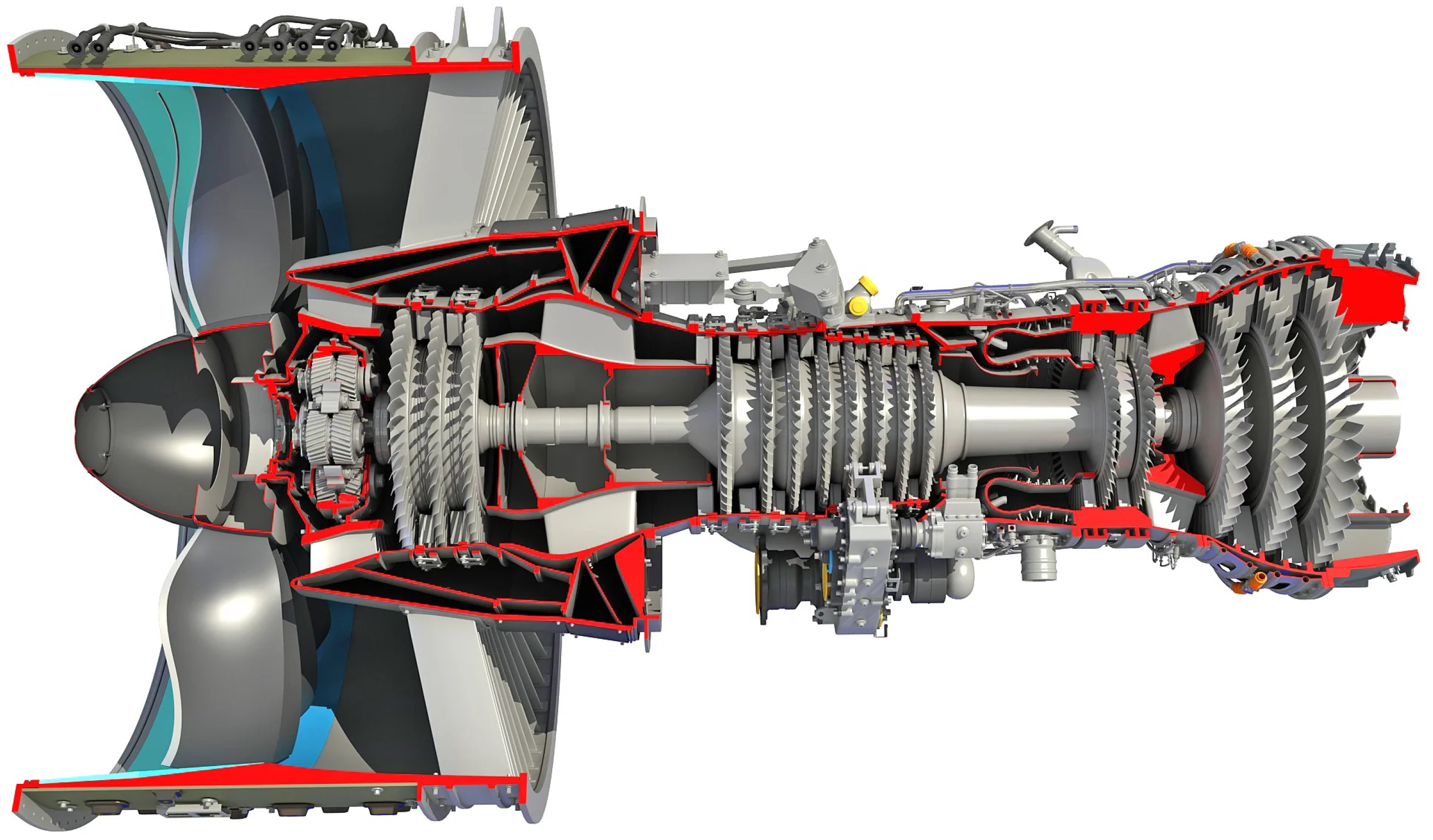
The integration of SACOCs into future propulsion systems creates new challenges and opportunities, particularly in the context of hybrid-electric architectures and ultra-high bypass ratio (UHBR) engines like Rolls-Royce UltraFan or Pratt and Whitney PW1000G (
Figure 8). These next-generation systems introduce increased thermal loads (even up to 100 MW of fan power) and reduced availability of traditional heat sinks (especially when fuel consumption is decreased). In hybrid-electric configurations, power electronics, batteries, and electric motors all contribute significant waste heat, which must be managed by a highly integrated thermal management system. SACOCs, with their advantages, are well positioned to support this function but must be adapted to operate effectively under different mission profiles and variable engine operating conditions [
31]. In UHBR engines, the increased fan diameter and reduced core flow limit the effectiveness of core-mounted cooling strategies, creating a greater dependence on the bypass stream for heat rejection. As a result, SACOCs must be designed to conform to increasingly constrained aerodynamic and structural envelopes, often within curved duct geometries or composite casings. This requires enhanced flexibility in SACOC architecture and integration with structural components, which could lead to multifunctional heat exchanger designs that simultaneously provide load-bearing, acoustic, and thermal management functions.
7.2. Smart SACOCs (Adaptive Fins, Real-Time Monitoring)
Emerging trends in aerospace thermal management point toward the development of “smart” SACOCs that incorporate adaptive features and real-time sensing to respond dynamically to changing flight and engine conditions. Unlike conventional passive designs, smart SACOCs could integrate shape-memory alloys, piezoelectric actuators, or thermally responsive materials to alter fin geometry or flow pathways during operation, optimizing performance across a wider operating envelope [
33]. For example, variable-geometry fins could minimize drag during cruise while expanding surface area during high thermal load events such as takeoff or climb. In parallel, embedded sensors capable of measuring oil temperature, pressure, vibration, or local heat flux would enable condition-based monitoring and predictive maintenance, reducing the risk of thermal failure and improving reliability. Lumped-parameter and reduced-order models linked to real-time data streams could provide onboard diagnostic tools to adapt thermal strategies in response to flight mission profiles. Although still in early research phases, these smart SACOC systems align with broader trends in “more-electric” and “intelligent” engine systems, where adaptability and autonomy are becoming core performance attributes.
7.3. Sustainability and Fuel Efficiency Impact
SACOCs also play an increasingly strategic role in the broader goals of aviation sustainability and fuel efficiency. As regulatory pressures and industry commitments push towards lower CO
2 and NO
x emissions, improving the thermal efficiency of propulsion systems becomes essential. Effective oil cooling directly contributes to reduced mechanical losses, extended engine life, and higher component reliability, all of which support lower specific fuel consumption throughout the engine’s lifecycle. More critically, optimized SACOC designs can enable higher overall engine pressure ratios and bypass ratios by alleviating thermal bottlenecks, indirectly improving thermodynamic efficiency. Studies such as those by Liu et al. [
34] have highlighted the link between thermal system management and engine failure modes, suggesting that proactive cooling strategies can mitigate hot-spot-induced degradation. Furthermore, integrating SACOCs with advanced fuel-saving engine cycles or hybrid-electric systems requires high adaptability and compactness to maintain overall system efficiency. As part of a holistic thermal management architecture, SACOCs contribute not only to engine-level improvements but also to fleet-wide reductions in fuel burn and emissions, aligning with the industry’s long-term decarbonization strategies.
8. Conclusions
Surface Air-Cooled Oil Coolers (SACOCs) have become a critical component in the thermal management strategies of modern and future turbofan engines. As engine architectures evolve toward higher bypass ratios, increased electrification, and compact integrated systems, SACOCs offer a viable and efficient means of dissipating thermal loads using the bypass airstream. This review has outlined the fundamental working principles of SACOCs; their challenges in aerodynamic and thermal integration; and the significant role they play in optimizing engine reliability, fuel efficiency, and performance.
A wide range of experimental and numerical studies have been conducted to evaluate and enhance the performance of SACOCs. These efforts have included the characterization of fin geometries, mitigation of pressure loss, and heat transfer optimization through conventional and advanced techniques such as Additive Manufacturing. Furthermore, this article has highlighted the adoption of high-fidelity CFD tools, transonic wind tunnel testing, and smart materials as emerging enablers for next-generation SACOC designs.
In the future, SACOCs are expected to play a central role in the thermal architecture of hybrid electric propulsion, ultra-high bypass engines, and intelligent aerospace systems. Their integration into multifunctional structures, adaptive designs in real time, and engine cycles driven by sustainability underscores the need for continued innovation in both modeling and experimental validation. Addressing these challenges will not only support the development of efficient propulsion systems but will also contribute to the broader decarbonization and performance goals of the aviation industry.
Unfortunately, some of the studies described raised confusion, especially in the context of studies with relatively low Reynolds Numbers. Also, the Meretith effect is more of a curiosity than a meaningful phenomenon.
All presented studies lack an analysis of the effect of ambient temperature on the efficiency of SACOCs. For example, in hot climates, assuming an air temperature above the runway of 320 Kelvins and lower air density than standard atmosphere, we can easily reach above 400 Kelvins just before SACOCs.


