1. Introduction
As the global demand for reduced emissions and reliable energy supply grows, renewable energy sources (RESs) are being increasingly adopted. Due to their inherent variability and intermittency, RESs are often coupled with energy storage systems (ESSs), which act as buffers between energy generation and consumption [
1].
ESSs play a crucial role in modern power distribution networks by enhancing grid stability and operational efficiency. They provide a wide range of services across different time scales. In the short term—ranging from seconds to minutes—ESSs support voltage and frequency regulation and system stability and help mitigate fluctuations in renewable energy output. Over longer durations, spanning several hours, ESSs enable renewable energy time-shifting and contribute to peak demand reduction, thereby increasing overall grid resilience [
2].
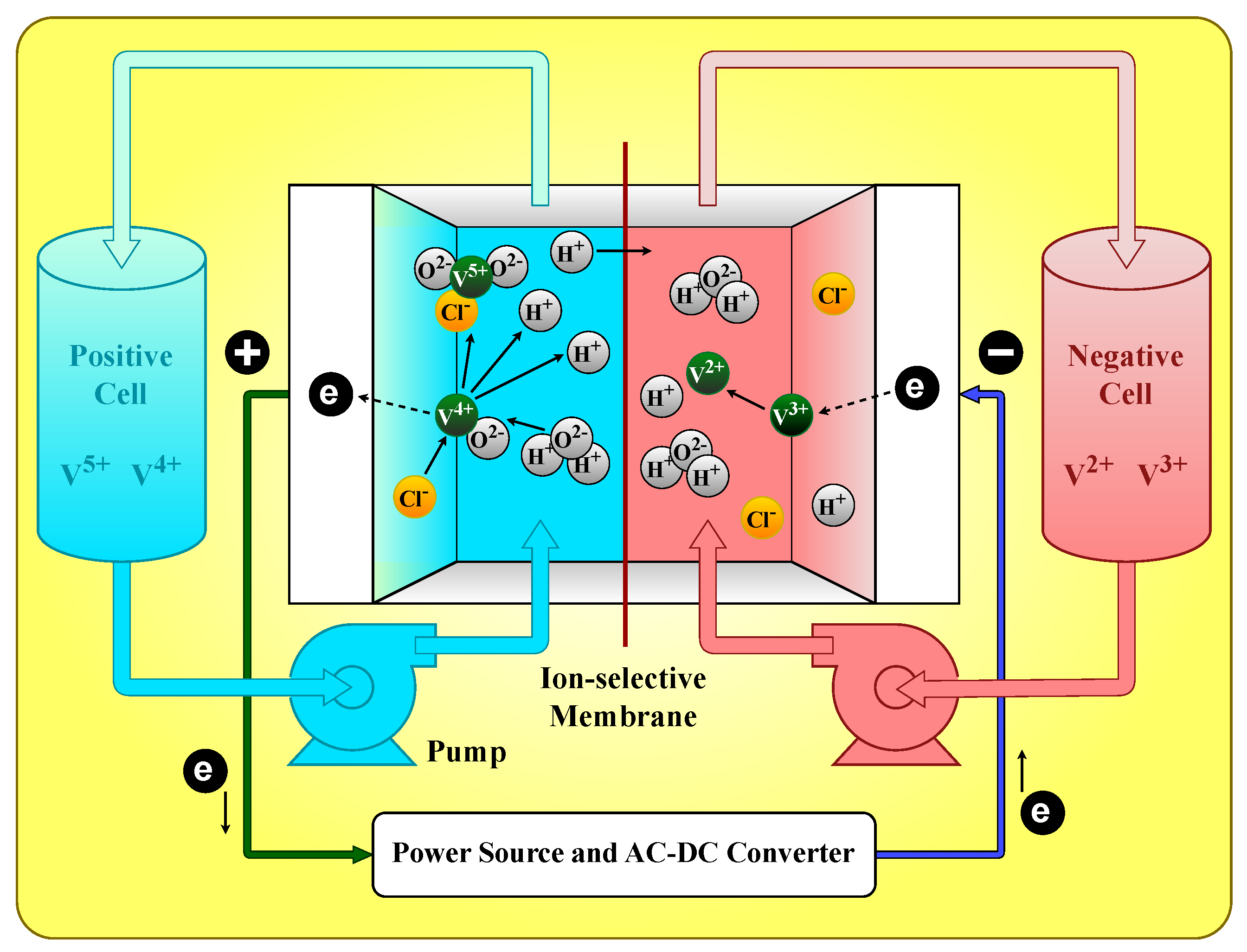
Among various ESS technologies, vanadium redox flow batteries (VRFBs) have attracted significant attention due to their unique advantages.
Figure 1 shows the structure of a VRFB, illustrating its operating principle. VRFBs offer long cycle life, the ability to discharge deeply without degradation, and high overall efficiency [
3]. These characteristics make VRFBs particularly suitable for large-scale grid integration, where durability, reliability, and efficiency are paramount [
4,
5].
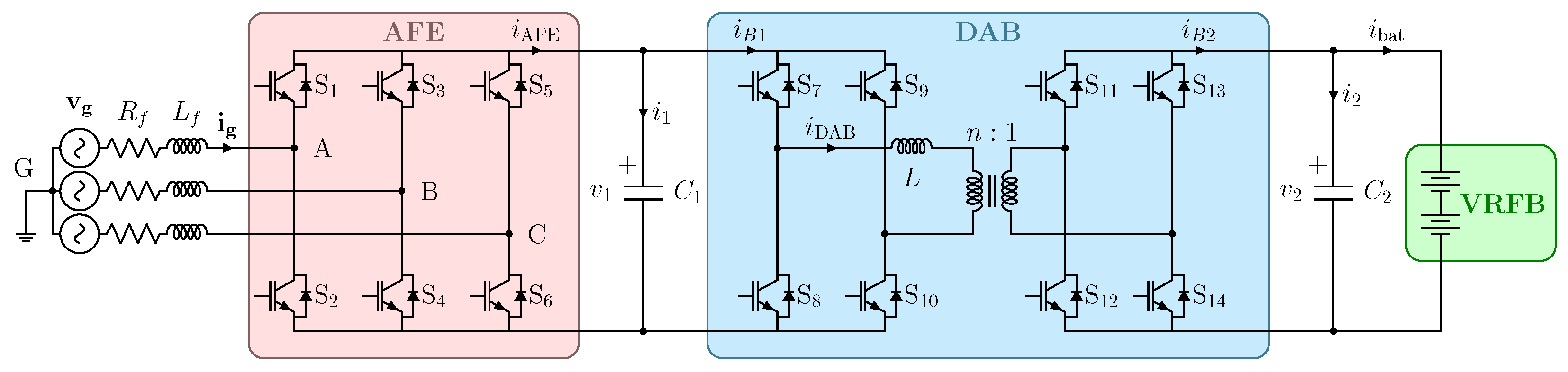
Since VRFBs are inherently DC systems, their integration into low-voltage AC (LVAC) grids requires bidirectional DC-AC conversion. This typically involves a two-stage power conversion system: an isolated DC-DC stage, such as a dual active bridge (DAB), to boost the battery’s low voltage and ensure galvanic isolation, followed by a DC-AC stage functioning as an active front-end (AFE) converter [
4]. Traditionally, each stage is controlled independently using dedicated PI controllers [
6]. The AFE employs an outer voltage control loop with an inner current loop, while the DAB stage usually controls output voltage or current. However, this independent design can lead to mutual interference between controllers, especially during transient conditions or reference changes.
Recently, time-domain control techniques like model predictive control (MPC) have emerged as promising alternatives for managing complex power electronics systems. MPC offers several advantages over conventional PI controllers, including faster reference tracking, straightforward handling of system constraints, and natural accommodation of multiple-input multiple-output (MIMO) system dynamics. A modulated MPC (MMPC) algorithm applied to a DC-AC converter has demonstrated effective unified control of both conversion stages through a single control action [
7,
8]. This approach minimizes a single cost function to optimize control inputs for both stages simultaneously, enabling faster tracking and eliminating controller interference.
Nonetheless, MPC implementations face two key challenges. First, they typically require higher computational resources compared to PI controllers. However, recent advancements in DSP- and FPGA-based control hardware, alongside algorithmic improvements, have mitigated this limitation [
9]. Second, MPC performance heavily depends on accurate system parameters; discrepancies between real and modeled parameters can lead to control failure or steady-state offsets. For effective MPC implementation with VRFBs, an equivalent circuit model is necessary to capture their multi-physics behavior.
Accurate estimation of internal states and parameters of batteries has become essential to ensure performance, safety, and reliability in energy storage systems and electric vehicles. A wide range of techniques have been proposed to address this challenge. In [
10], a robust sliding-mode observer based on a nonlinear battery cell model enables precise state of charge (SOC) estimation, even under model uncertainty and parameter variations due to aging. The method also shows reduced sensitivity to sensor noise and improved performance over traditional estimators such as the Luenberger observer and extended Kalman filter (EKF). However, the sliding-mode gain may introduce high-frequency oscillations in the estimated SOC, and the computational time, though efficient, is slightly higher than that of EKF-based approaches. In [
11], a Wiener model combined with an extended kernel iterative recursive least squares (EKIRLS) algorithm allows real-time identification of equivalent circuit parameters, enhancing SOC estimation accuracy via an EKF. The approach provides a favorable balance between nonlinearity representation and computational efficiency. Nevertheless, it may amplify measurement noise due to reliance on signal derivatives, and small deviations in SOC estimation are observed under low charge levels or strong polarization effects. In [
12], frequency-domain decomposition through active current injection is used in a sequential estimation scheme to decouple SOC, state of health (SOH), and circuit parameters. This separation significantly improves estimation accuracy, but the method requires precise control of current profiles and is less applicable in pure battery systems (e.g., PEVs) where current injection is infeasible. Furthermore, full convergence of some parameters, such as RC time constants, may be slow. In [
13], an improved adaptive battery state estimator (ABSE) jointly estimates SOC and the state of available power (SOAP), accounting for current-dependent internal resistance. The method shows excellent performance across different aging levels but relies on a priori knowledge of SOC–OCV and SOC–resistance relationships. Additionally, estimation accuracy can degrade during constant-voltage charging due to reduced sensitivity between input and output variables. A data-driven perspective is provided in [
14], where support vector regression (SVR) optimized by NSGA-II is used for SOH estimation based on short-duration current pulse features. The method offers flexible model complexity and strong generalization capability, yet becomes unstable if too few features are selected and suffers from long testing times or unrealistic requirements (e.g., very low currents) when using capacity or differential voltage-based indicators. In [
15], a robust identification algorithm based on eigenvalue addition/deletion least squares with a forgetting factor (MIFRLS) is introduced, addressing singular covariance issues and enabling parameter tracking even under zero-current conditions. While computationally efficient, the method still inherits some challenges from traditional FRLS, including sensitivity to tuning thresholds and limited treatment of current measurement noise. In [
16], a double RC equivalent circuit model is proposed, where resistive and capacitive lumped elements represent VRFB dynamics and power losses. Using battery voltage and current measurements from full charge–discharge cycles, model parameters are identified via particle swarm optimization. However, due to complex multi-physics effects, operational temperature variations, and battery aging, these equivalent parameters tend to vary over time, challenging controller accuracy. Despite their individual advantages, these model-based and data-driven approaches face limitations in balancing physical interpretability, generalization, and robustness to measurement noise or parameter drift.
To address this, data-driven methods like physics-informed neural networks (PINNs) offer a powerful alternative. PINNs embed known physical laws directly into the neural network architecture or loss function, ensuring that model outputs remain consistent with governing equations while retaining the expressive capacity of deep learning. By fusing domain knowledge with data-driven learning, PINNs enable accurate, physically consistent, and data-efficient parameter estimation, even under limited, noisy, or partially observed measurements, thereby overcoming many of the shortcomings of conventional estimation frameworks [
17,
18].
Recent studies have explored the integration of PINNs into various power and energy system applications, demonstrating their potential to enhance accuracy, robustness, and physical consistency. In [
19], a hybrid LSTM-PINN model is proposed for estimating the temperature distribution in lithium-ion battery packs. By combining a physics-based lumped thermal model with an LSTM and a feedforward neural network, and embedding heat transfer equations into the loss function, the approach improves accuracy at locations lacking direct measurements and accelerates convergence compared to purely data-driven methods. However, its effectiveness depends on careful hyperparameter tuning and ambient temperature modeling, and it may pose challenges for real-time implementation due to computational cost. In [
20], an extended PINN (e-PINN) framework is developed for parameter identification in switched-mode power converters with undetermined topological durations. The architecture incorporates a pseudolabel generation network and multiple time-segmented PINNs, enabling online identification without requiring high-frequency sampling or additional sensing hardware. While the method is robust to noise and effective in practical settings, it faces limitations when estimating weakly observable parameters such as diode forward voltage or parasitic resistances. A distinct approach is presented in [
21], where an inherently interpretable PINN, referred to as Battery Neural Network (BattNN), is designed for battery modeling and prognosis. By embedding the dynamics of an equivalent circuit model (ECM) directly into the network structure, BattNN enables accurate voltage and end-of-discharge (EOD) predictions under arbitrary load profiles, with minimal data and computational demand. Nonetheless, the model does not incorporate battery aging effects and may require manual tuning for less influential parameters. In the domain of power electronics, ref. [
22] applies PINNs for online impedance identification of voltage source converters (VSCs) across varying operating points and frequencies. The method restructures the neural network based on an analytical impedance model and leverages transfer learning to adapt from offline simulations to real-time data, achieving efficient and accurate impedance estimation from sparse measurements. Still, the approach depends on well-designed perturbation signals and requires multiple independent excitations to fully identify the system’s impedance matrix. While each of these approaches addresses specific challenges in battery and converter modeling, they share common limitations, including computational complexity, sensitivity to hyperparameter configuration, and limited scalability to evolving system dynamics or long-term degradation. Nevertheless, by embedding physical laws into learning processes, PINNs offer a compelling pathway toward physically consistent, data-efficient, and generalizable models, bridging the longstanding gap between black-box neural networks and traditional model-based approaches.
Therefore, this paper presents a lightweight PINN framework that directly embeds the discrete-time state-space dynamics of a VRFB into its architecture. The proposed model simultaneously predicts the terminal voltage and estimates five discrete-time physical parameters associated with the RC dynamics and internal resistance of the system. By eliminating hidden layers, the model retains interpretability while ensuring computational efficiency. Training is performed in two phases: an initial convergence phase using the Adam optimizer, followed by fine-tuning with the L-BFGS algorithm. The model’s performance is assessed through prediction accuracy, parameter identifiability, and statistical error analysis. Once trained, the PINN is integrated into a MMPC scheme for a dual-stage DC-AC converter. Simulation and hardware-in-the-loop results demonstrate that the adaptive tuning of the PINN-estimated parameters enables the controller to track variations in VRFB behavior, thereby improving both the performance and robustness of the MPC system.
2. Model of the System
Figure 2 illustrates the DC-AC converter topology adopted for interfacing the VRFB with the grid. The architecture comprises a three-phase inverter operating as an AFE and a DAB for the DC-DC stage.
The state-space equations of the system must be derived to correctly implement the MMPC. On the grid side, the system equations can be written in the
stationary frame as follows:
where
,
,
, and
are the grid current and voltage on the
and
axes, respectively,
is the voltage on the DC-link capacitor
between the two conversion stages,
and
are the AC filter resistance and inductance, and
and
are the converter switching functions on the
frame.
The DC-link voltage
is obtained with the current balance equation at the capacitance
node:
where
is the DAB input current and
is the current on the DC side of the AFE. The latter is obtained as
The exchanged power
P between the two bridges of a DAB operating under single-phase shift (SPS) modulation is given by
where
is the phase shift,
is the switching frequency,
n is the transformer turns ratio, and
L is the total leakage inductance referred to the primary side. From (4), the average value of the input and output currents can be obtained as
where
is the voltage on the capacitive filter between the DAB and the VRFB. At the moderate switching frequency of 20 kHz used in this study, parasitic capacitance, dead-time effects, and transformer core losses have limited impact on power flow and system-level dynamics, justifying their omission from the control-oriented model. The VRFB is modeled through an equivalent circuit model introduced in [
16]. This model includes two
branches, characterized by the parameters
,
,
, and
, which represent the activation and concentration losses, respectively. An additional series resistance
accounts for the remaining ohmic losses. To model self-discharge behavior, a resistor
is connected in parallel with the open-circuit voltage
of the battery. The resulting VRFB model can be described by the following set of equations:
where
is the VRFB current. The open-circuit voltage can be expressed as a function of the battery SOC. This model of the battery has demonstrated a strong correspondence with the real system behavior, supporting its validity [
16].
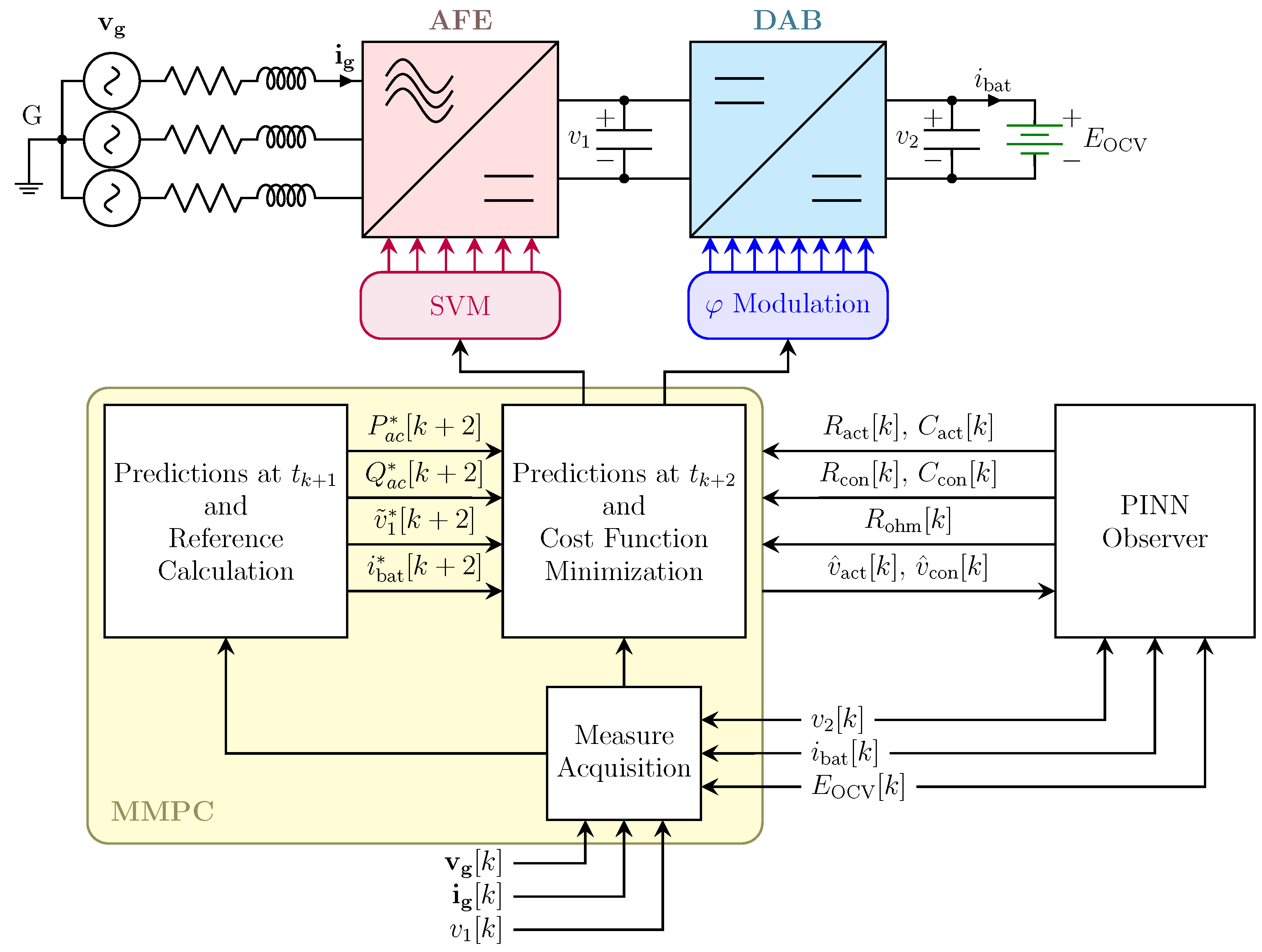
4. PINN Architecture
A lightweight PINN was developed to accurately predict the future terminal voltage of the VRFB while simultaneously estimating the parameters of its internal equivalent circuit. The network embeds established battery dynamics directly into its structure, preserving physical interpretability and ensuring high prediction accuracy with minimal computational overhead.
The model receives a five-dimensional feature vector at each discrete time step, specified as follows:
The model produces a scalar output corresponding to the predicted terminal voltage at the next time step, denoted as . Whereas standard black-box architectures ignore underlying physics, the PINN enforces the governing equations of the VRFB’s equivalent circuit model (7)–(9). The parameters are obtained directly from data and provide discrete-time approximations of the two underlying first-order RC dynamics. Temperature notably influences the internal dynamics of VRFB systems, affecting parameters such as , , , , and ; in this work, the PINN implicitly captures these time-varying parameters and their latent dependencies—such as those due to temperature and SOC—directly from input–output data, without requiring explicit thermal modeling or direct temperature measurements. Owing to the physical interpretability of its parameters, the model is suitable for both forecasting and system identification.
4.1. Loss Function and Training Objective
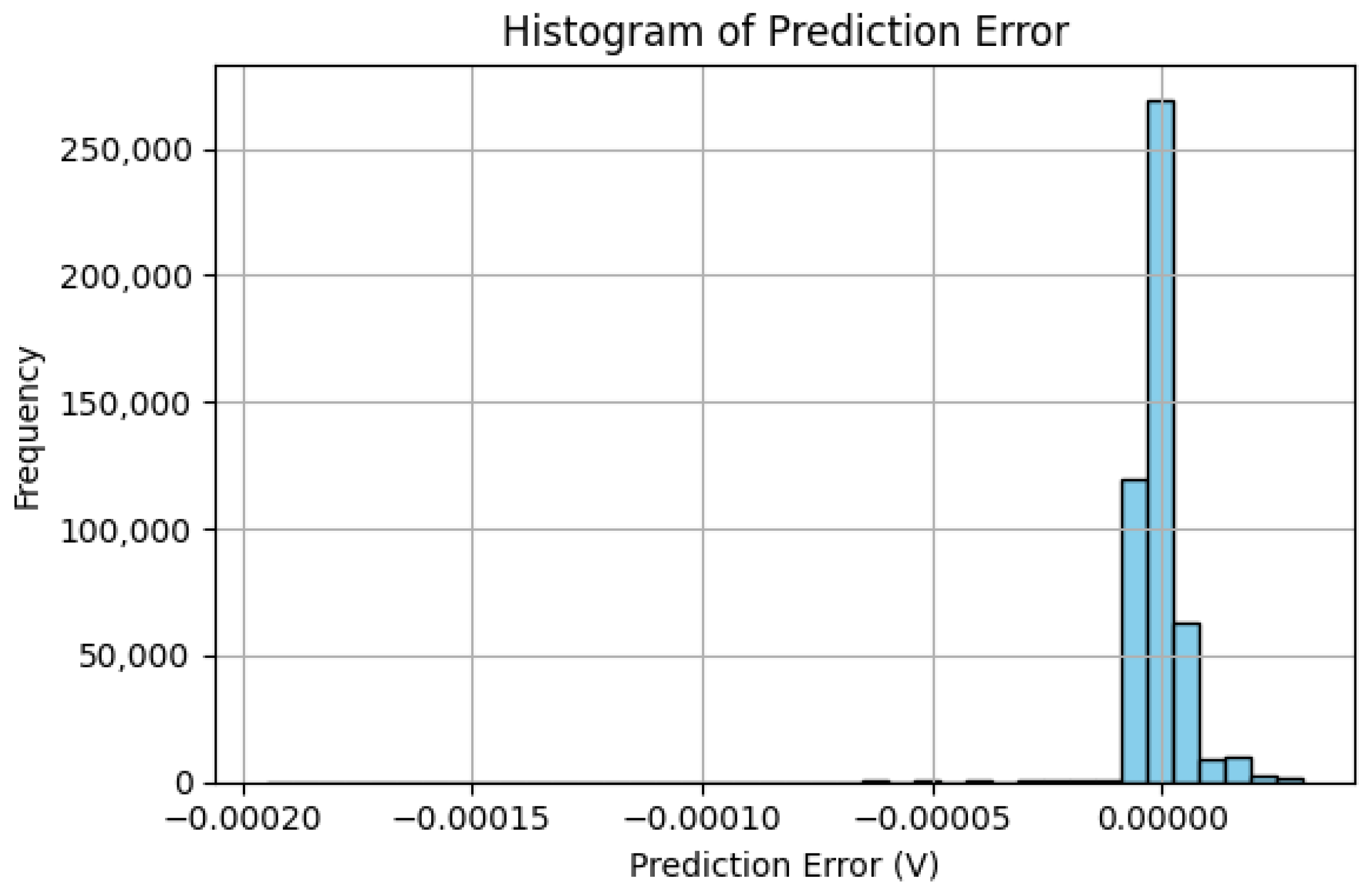
The training objective is to minimize the discrepancy between the predicted and actual terminal voltages over the course of the training horizon. While additional terms could be introduced to penalize residuals from internal RC dynamics (e.g., deviations from expected state transitions of
and
), this study focuses solely on terminal voltage prediction. This decision reflects the model’s intended use in predictive control applications, where
is the key regulated quantity. Limiting the loss to this target ensures both computational efficiency and suitability for real-time implementation. The loss function is represented by the mean squared error (MSE), which is represented as follows:
Consistency of the RC branch voltages is inherently enforced through the governing equations of the internal states, and although the loss function (16) minimizes terminal voltage errors, the internal dynamics—including the RC branch behavior—are embedded within the physics-informed network structure, as detailed in (7) and (9). The model employs a shallow architecture with a single hidden layer (Model A: 1 × 32 neurons) to regress the parameters , , , , and , which are then used within embedded discrete-time governing equations to compute the predicted voltage. Thus, the model’s structure reflects a physics-informed approach where physical laws are hard-coded into the forward pass rather than imposed through loss penalties.
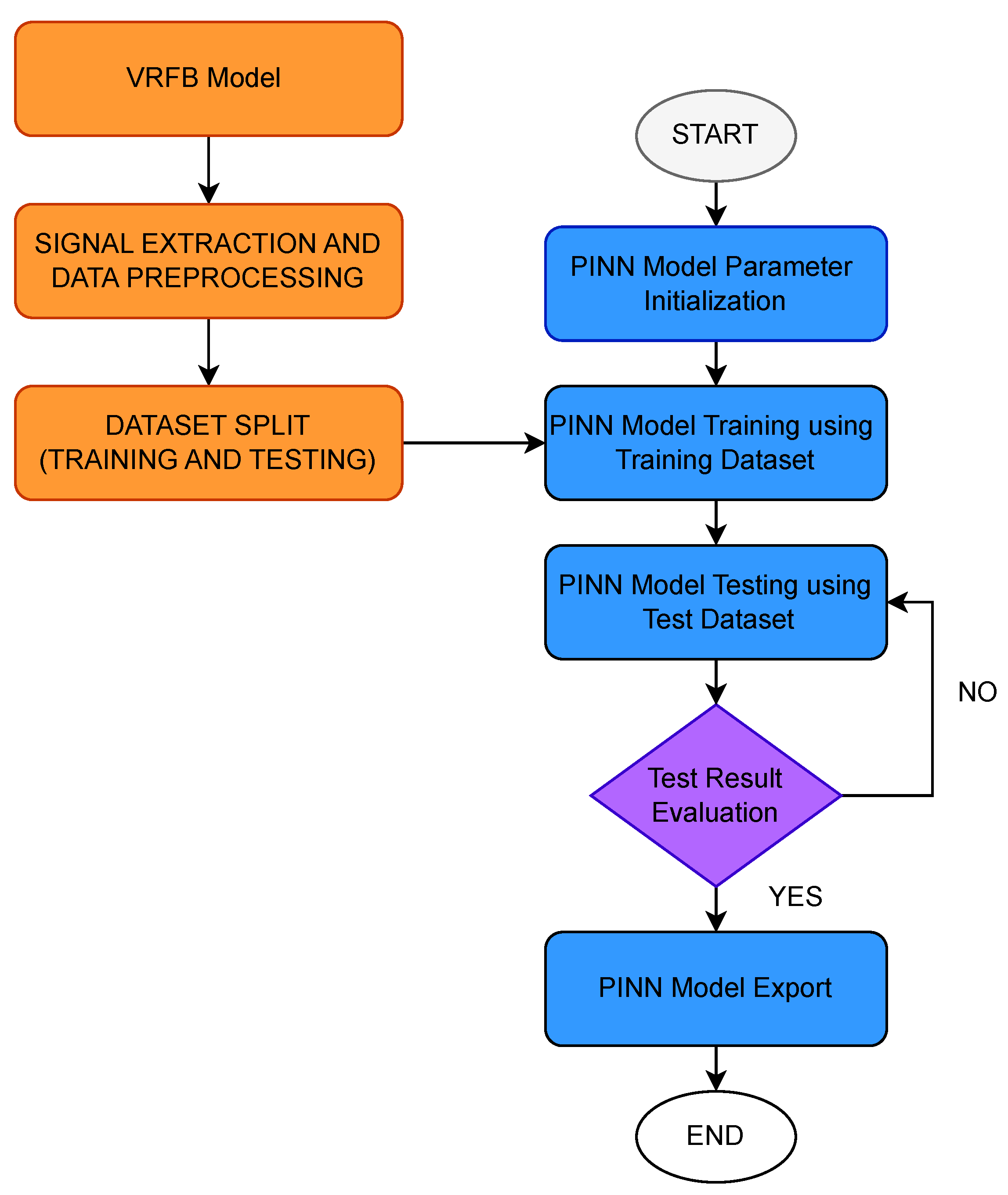
4.2. Two-Phase Optimization Strategy
To ensure robust convergence and high precision of the learned physical parameters, a two-phase optimization scheme is employed:
Phase I—Adam Optimization: The model is trained using the Adam optimizer for 5000 epochs with a learning rate of . Gradient clipping (max-norm = 1.0) is applied to ensure numerical stability during early learning stages.
Phase II—L-BFGS Refinement: Once the model has converged with Adam, parameter refinement is performed using the L-BFGS optimizer with line search (strong Wolfe conditions), which is well-suited for final fine-tuning in low-dimensional parameter spaces.
The final trained model is stored in a PyTorch 2.6-compatible .pt file containing five scalar parameters. These parameters are then exported as a MATLAB 2023a-compatible structure or injected directly into a Simulink user-defined function block, enabling real-time prediction and closed-loop integration in an MPC environment. The governing equations are thus preserved in both training and deployment, ensuring physical consistency throughout the estimation–prediction–control pipeline. Finally, during the real-time operation, the PINN is constantly fine-tuned to adapt to different conditions of operation and variations in VRFB parameters.
6. Simulation Results
This section presents the simulation results of the proposed MMPC.
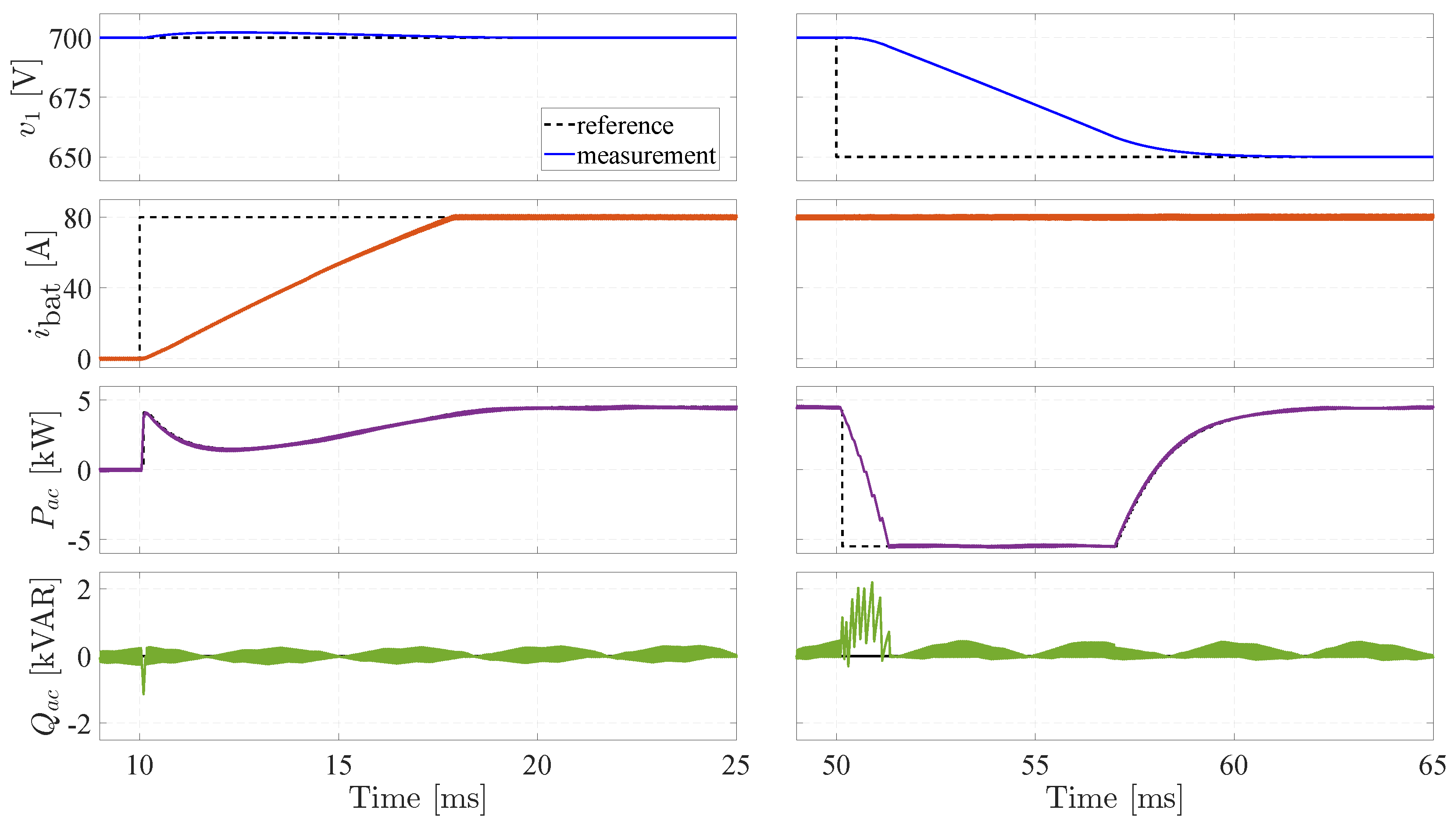
Figure 7 displays the DC-link voltage, battery current, and the active and reactive power exchanged with the grid across two distinct scenarios, corresponding to each column in the figure.
In the first scenario, the system response is evaluated when the battery reference current steps from 0 A to 80 A, while the DC-link voltage and grid reactive power references are held constant at 700 V and 0 kVAR, respectively. The new current reference is tracked within approximately 7 ms, exhibiting no overshoot, undershoot, or oscillations, and causing no disturbance to the DC-link voltage or reactive power. The MMPC internally adjusts the active power reference to meet the updated battery current setpoint.
In the second scenario, the DC-link voltage reference changes from 700 V to 650 V, while the battery current and grid reactive power references remain at 80 A and 0 kVAR, respectively. The voltage setpoint is reached within about 8 ms, without overshoot, oscillations, or disturbance to the battery current. During this transient, active power reverses to discharge the DC-link capacitor, and reactive power briefly deviates in response to the voltage step but returns to 0 kVAR within 1 ms.
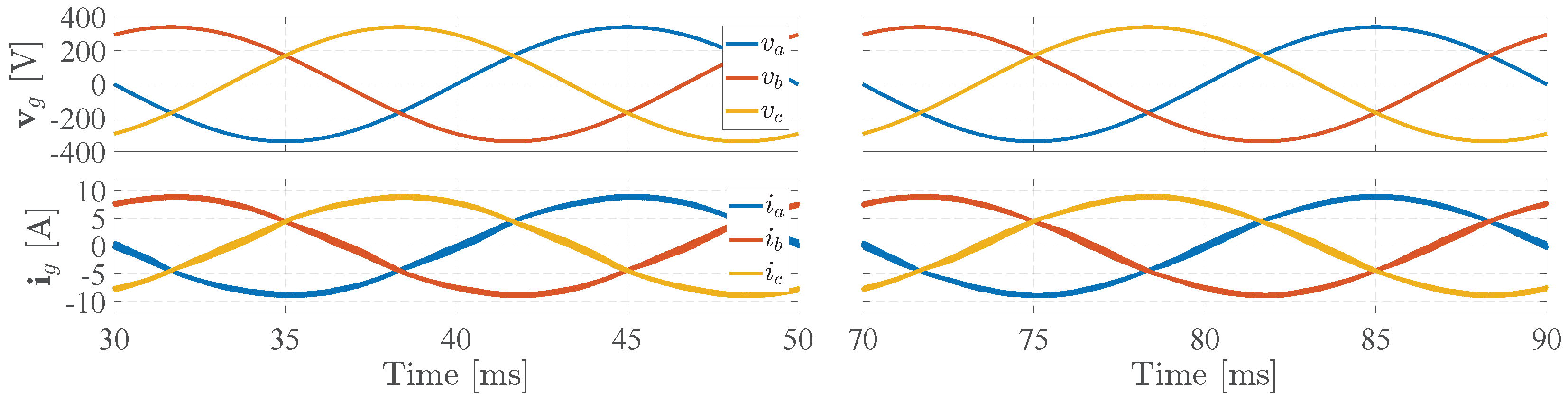
Figure 8 presents the simulation results of the grid phase voltages (top) and line currents (bottom). The left column corresponds to the scenario in which the reference values for the DC-link voltage, battery current, and grid reactive power are 700 V, 80 A, and 0 kVAR, respectively. The right column refers to the case where these reference values are 650 V, 80 A, and 0 kVAR. The total harmonic distortion (THD) of the grid current, calculated as the average of the THD values of the three line currents, is 2.94% and 2.62% in the first and second scenarios, respectively.
Controller Robustness
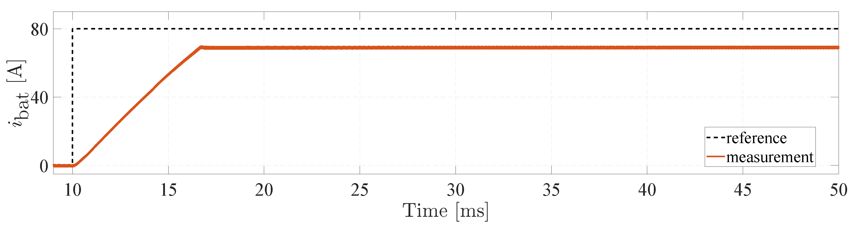
The contribution of the PINN observer to controller robustness is assessed by evaluating its performance under parameter mismatch conditions. To evaluate the system’s performance under conditions significantly deviating from nominal operation, all parameters associated with the VRFB’s dynamics and losses are artificially increased by 25%. This test is conducted while the controller continues to operate based on nominal parameter values. Since these are equivalent circuit parameters, their variation due to factors such as aging or temperature is not straightforward to quantify analytically. Consequently, applying a uniform 25% increase—though extreme—serves as a reasonable approximation of a highly off-nominal scenario, allowing assessment of the controller’s robustness under substantial model mismatch.
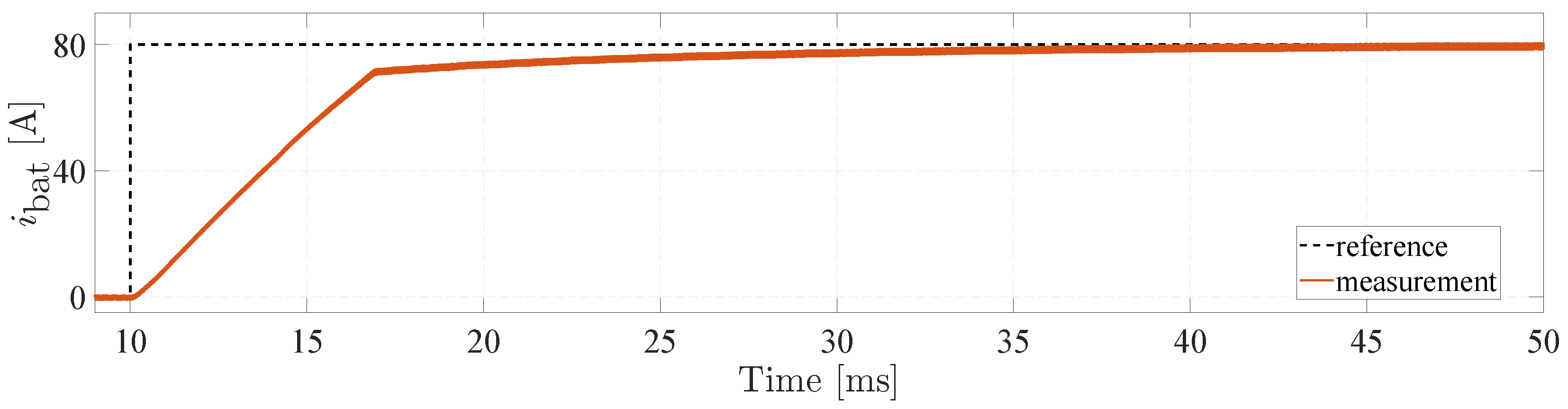
Figure 9 presents the simulation results for a step change in the battery current reference from 0 A to 80 A. Once the system reaches steady state, a noticeable tracking error appears, highlighting the discrepancy between the actual and reference battery current due to parameter mismatch.
Figure 10 presents the results for an identical scenario with the PINN observer enabled to continuously update the VRFB parameters. Under these conditions, the battery current reference is tracked with high accuracy, exhibiting only a negligible steady-state offset after the transient phase. These findings confirm that the integration of the PINN observer markedly enhances the robustness of the MMPC against uncertainties in system parameters.
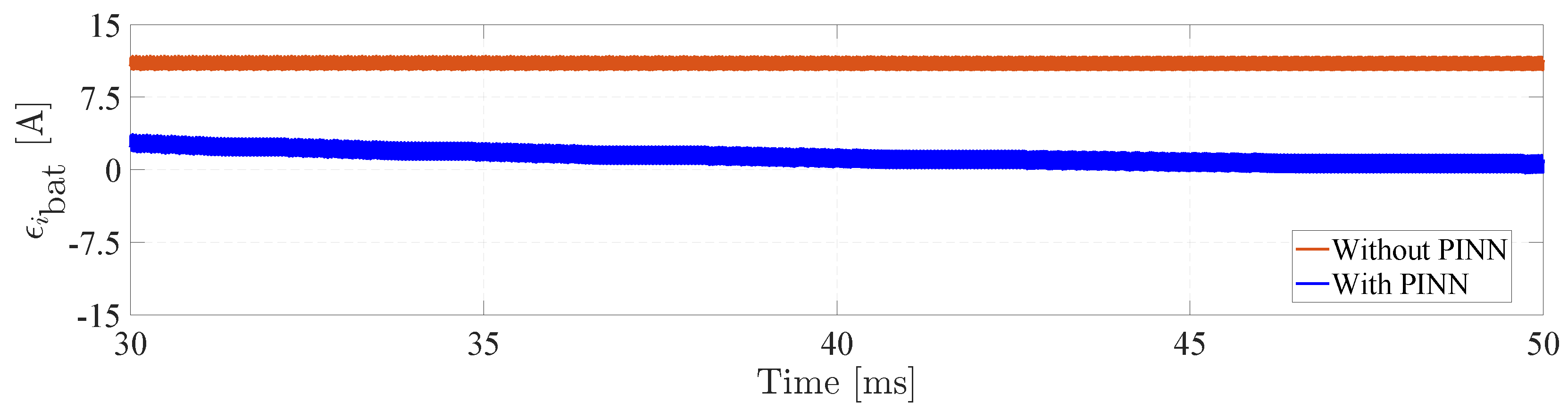
Finally,
Figure 11 compares the error between the battery current reference and the measured value, with and without the PINN observer. In both cases, the error signal exhibits oscillations due to the inherent ripple in the battery current. However, without the PINN observer, the error remains consistently positive and does not converge to zero. When the PINN observer is included, the error amplitude is significantly reduced and oscillates around zero, further demonstrating the effectiveness of the proposed approach.
7. Experimental Results
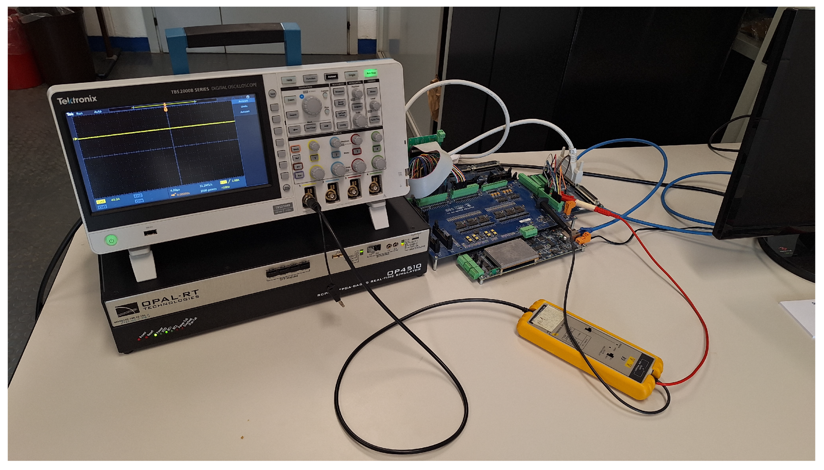
A hardware-in-the-loop (HIL) simulation was conducted to validate the proposed controller. The experimental setup, shown in
Figure 12, consists of an OP4510 real-time simulator (RTS) from OPAL-RT Technologies (Montreal, QC, Canada), equipped with a Kintex-7 FPGA and a 3.5 GHz processor. The converter, power plant, and battery models were developed using the Schematic Editor within the RT-LAB environment. The FPGA simulation operates with a time step of 120 ns, enabled by eHS Gen5, OPAL-RT’s real-time FPGA-based solver.
The control board, a PED-Board v3, integrates an sbRIO-9651 System on Module from National Instruments (Austin, TX, USA), featuring a real-time processor and a reconfigurable FPGA. Both the MMPC and the PINN are implemented on the FPGA using the LabVIEW FPGA module. Communication between the control board and an external host PC is established to enable monitoring and data exchange. Waveform measurements are carried out using a Pico TA057 (St Neots, UK) differential probe, and the results are visualized with a Tektronix TBS2000B (Beaverton, OR, USA) digital oscilloscope.
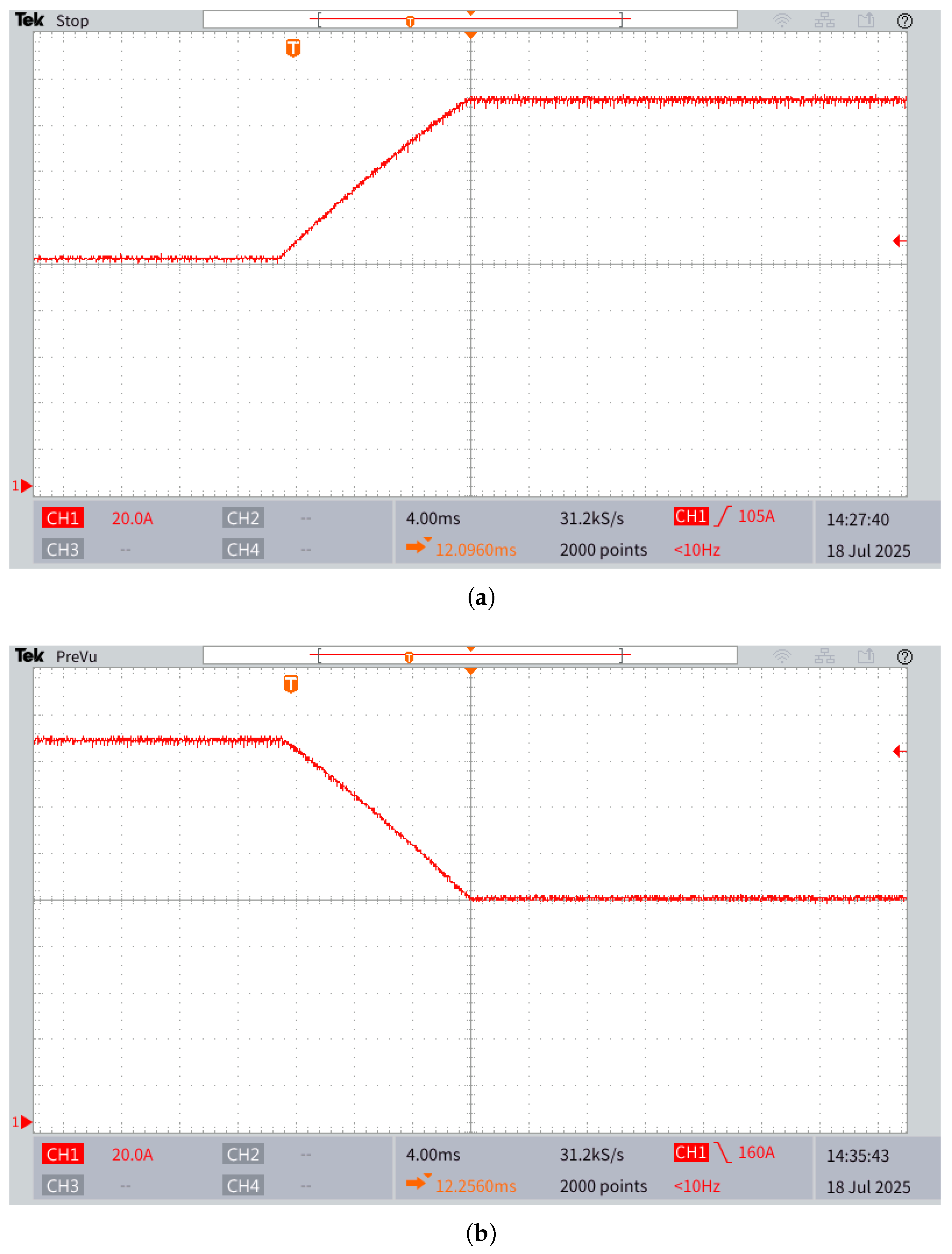
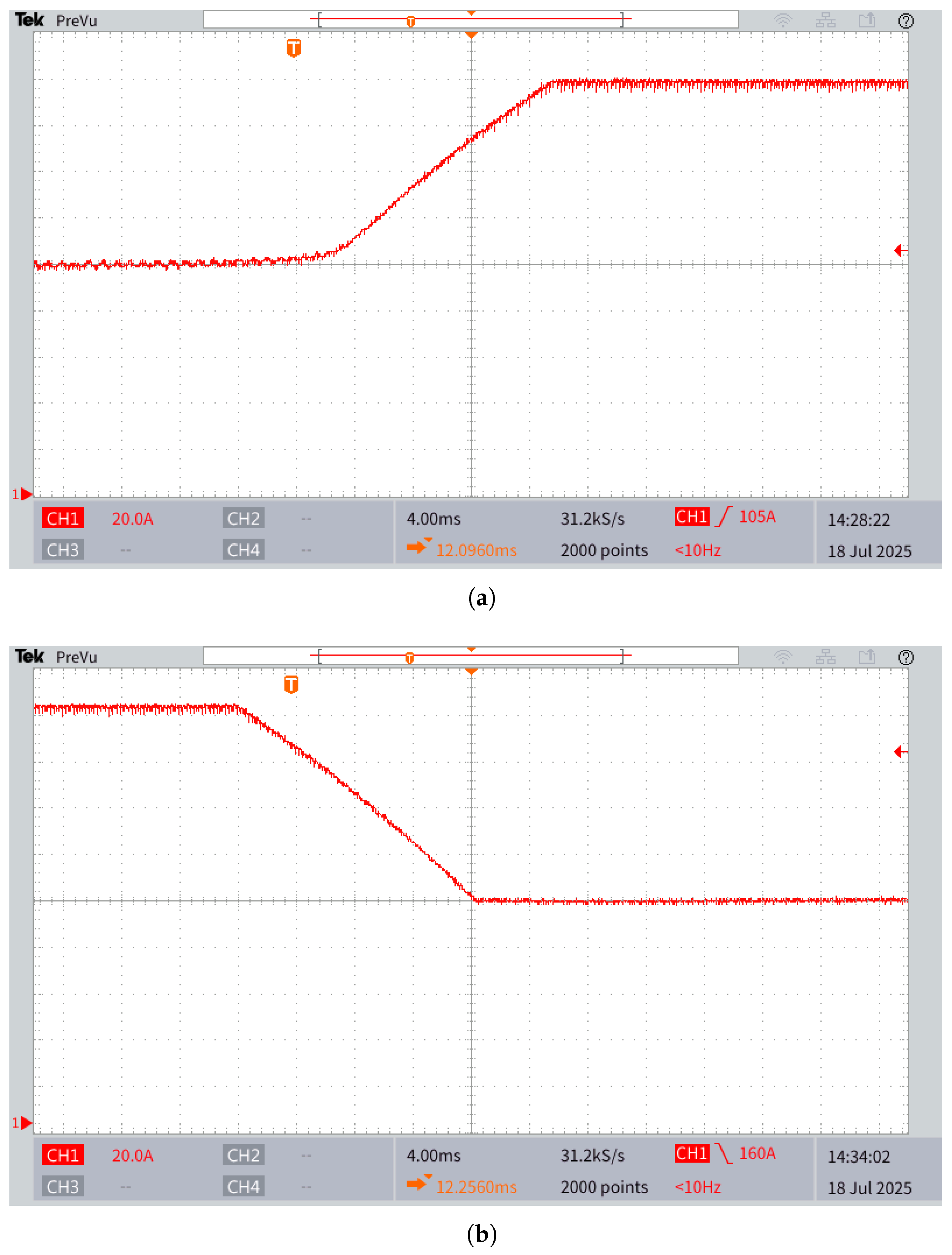
Figure 13 presents the experimental results of the battery current, with the MMPC operating under nominal parameters for the VRFB, while the parameters in the simulation are increased by 25%. Specifically,
Figure 13a illustrates the system response following a change in the battery current reference from 0 A to 80 A, whereas
Figure 13b shows the response for a step change from 80 A back to 0 A. The measured current fails to track the reference accurately due to parameter mismatches between the plant and the controller model.
On the other hand,
Figure 14 presents the battery current results when the PINN-based observer for the VRFB is integrated within the controller.
Figure 14a depicts the system response following a current reference step from 0 A to 80 A, while
Figure 14b shows the response for a step from 80 A to 0 A. With real-time parameter identification enabled by the PINN, the MMPC demonstrates significantly improved reference tracking in both scenarios.
Although incorporating the PINN observer increases the control algorithm’s execution time from 42 s to 48 s, it remains within the 50 s limit required to sustain a 20 kHz switching frequency.


 ,
, 