Article

An Additional Damping Control Strategy for Grid-Forming Energy Storage to Address Low-Frequency Oscillation

1
School of Electrical Engineering, Shenyang University of Technology, Shenyang 110870, China
2
School of Electrical Engineering, Shenyang Institute of Engineering, Shenyang 110136, China
*
Author to whom correspondence should be addressed.
Energies 2025, 18(15), 3971; https://doi.org/10.3390/en18153971
Submission received: 4 June 2025 / Revised: 15 July 2025 / Accepted: 21 July 2025 / Published: 25 July 2025

Abstract

Grid-forming (GFM) energy storage can be utilized as a backup power source for the power grid to ensure the security of the power grid. GFM energy storage can also enhance the strength of the power grid and improve its stability. However, the GFM energy storage inherits the characteristics of the synchronous generator. Low-frequency oscillations may occur in GFM energy storage, which affect the stable operation of the power system. This paper proposed an additional damping control strategy for GFM energy storage to address the low-frequency oscillation. Firstly, this paper builds the state-space small-signal mathematical model of the GFM energy storage grid-connected system to analyze the participation factors of the low-frequency oscillation mode and clarify the key control parameters affecting the GFM energy storage grid-connected system the low-frequency oscillation. Then, this paper proposed an additional damping control strategy to increase the damping ratio of the low-frequency oscillation mode and improve the stability of the GFM energy storage grid-connected system. Finally, semi-physical experiments verified the effectiveness of the proposed additional damping control strategy.

1. Introduction

Clean energy sources such as solar and wind power rely on inverters to connect to the grid. With the increasing requirements for carbon emissions, inverter-based resources (IBRs) are gradually replacing traditional synchronous generators (SGs) driven by fossil fuels [1]. The stability of the power grid is shifting from being dominated by SGs to being dominated by IBRs [2]. Most existing clean energy inverters adopt grid-following (GFL) control and rely on the phase-locked loop (PLL) for grid connection. For power sources, inverters that rely on PLL may experience oscillation instability in a weak grid, which may affect the stable operation of other equipment in the power grid [3]. Refs. [4,5,6] proposed various PLL optimization structures to optimize the stability performance of GFL inverters in weak grids. Furthermore, refs. [7,8] proposed PLL-less power-synchronized control strategies, which enable inverters to operate in ultra-weak grids. However, for the power grid, GFL inverters do not participate in grid frequency and voltage management, which reduces grid strength and affects grid reliability [9,10]. Improved GFL control strategies cannot fundamentally solve the stability problems of IBR-dominated power grids.
On the one hand, energy storage can increase the consumption rate of clean energy. On the other hand, it can smooth the output of clean energy and improve the stability of the power grid. Therefore, energy storage has been extensively integrated into the power grid with the development of clean energy. Compared to GFL-controlled energy storage, grid-forming (GFM) energy storage can actively provide voltage and frequency support. In addition, GFM energy storage can enhance the strength of the power grid and improve the stability of the regional power grid [11,12,13]. Therefore, GFM energy storage has received a lot of attention from researchers in recent years. Currently, the main GFM control strategies include droop control, virtual synchronous generator (VSG) control, virtual oscillator control (VOC), etc. Table 1 summarizes the characteristics of the various GFM control strategies. Droop control enables converters to have active-frequency and reactive-voltage droop output characteristics similar to SGs [14]. However, droop control converters do not have inertia response characteristics. VOC has a built-in self-synchronization mechanism, and multiple parallel VOC converters can spontaneously tend toward synchronization. However, the harmonic problem of the VOC has limited its promotion [15].
Compared with other GFM control strategies, the VSG control strategy has been more widely applied [16,17]. The VSG-controlled converter can simulate the droop characteristics of the SG and provide inertial support to the power grid. In addition, expanded VSG control strategies have also attracted the attention of researchers. Ref. [18] proposes a compensated generalized VSG control strategy (GCVSG). The GCVSG improves the stability of the converter in on-grid mode and enhances the inertial response capability of the converter in off-grid mode. However, the control parameter tuning of GCVSG relies on the impedance parameters of the power grid, and these parameters are difficult to obtain in practice; thus, the parameter tuning of GCVSG is relatively difficult. Ref. [19] proposes an adaptive VSG (AVSG) control strategy based on the online calculation of grid impedance. The AVSG improves the stability of GFM converters in strong power grids. However, the AVSG requires high performance from the controller, which increases the application cost of GFM converters.
The VSG control strategy makes the GFM energy storage have the dynamic characteristics of the SG [20,21]. However, the existing studies revealed that the VSG-controlled converter exhibits a low-frequency oscillation phenomenon similar to SG when the equivalent damping is insufficient [22,23]. This characteristic limits the development and promotion of the GFM energy storage.
For the low-frequency oscillation problem of the VSG-controlled converter, the current solutions can be classified into two types, i.e., optimizing the control parameters and adjusting the control structure of the VSG. Ref. [24] built the small-signal model of the VSG-controlled converter and analyzed the influence of the rotational inertia parameter and damping coefficient of the VSG control on the dynamic characteristics of the converter. Ref. [25] utilized the VSG power frequency small-signal closed-loop transfer function to investigate the differences and connections between the coupling of key VSG parameters and the low-frequency oscillation characteristics. Ref. [26] proposed a control method of adaptive change in the rotational inertia and the damping coefficient according to the variation in the converter angular velocity based on the stability analysis of VSG control parameters. However, the parameter adaptive method is difficult to implement in real converters due to the influence of control delay and measurement accuracy. Refs. [27,28] utilized machine learning to guide the design of the rotational inertia and the damping coefficient in the expectation of seeking the optimal control parameters of the VSG control strategy, but the control parameters of the VSG actually not only need to consider the stability of the individual VSG, but also the stability requirements of the power system [29]. Therefore, the control parameters of the VSG with better stability could be obtained by the stability analysis method, but the adjustment of the VSG control parameters could not completely solve the low-frequency oscillation problem of the VSG.
Refs. [30,31] designed a virtual power system stabilizer control loop for the VSG with reference to the principle of the power system stabilizer applied to the SG in order to solve the low-frequency oscillation problem of the VSG. However, the control loop involves several control parameters, and it is difficult to adjust the parameters. Ref. [32] proposed a VSG damping calibration control method based on state feedback, but the method weakened the original inertial response capability of the VSG. Contrastingly, Ref. [33] analyzed the effect of the reactive power loop feed-forward on improving the stability of VSG control and proposed a reactive power feed-forward control strategy to avoid low-frequency oscillations of the VSG during the power grid fault. However, the control strategy requires the phase-locked loop (PLL) to obtain the frequency of the power grid, and the PLL may affect the stability of the VSG. Ref. [34] proposed another reactive power feed-forward control strategy, which improved the stability of the VSG control strategy and suppressed low-frequency oscillations without the PLL, but the structure of the additional control is complex and difficult to apply in practice.
Common small disturbance stability analysis methods include eigenvalue analysis, impedance analysis, amplitude–phase dynamics analysis, etc. [35,36]. In particular, eigenvalue analysis can reveal oscillation modes of converters, accurately calculate the influence factors of all the oscillation modes, and comprehensively analyze the stability of converters. Therefore, this paper adopts eigenvalue analysis to analyze the low-frequency oscillation stability of the GFM energy storage system. This paper builds a detailed state-space small-signal mathematical model of the GFM energy storage and analyzes the influencing factors that cause low-frequency oscillations of the GFM. Then, an additional damping control strategy for the GFM energy storage is proposed in this paper to cope with low-frequency oscillations, which improves the stability of the GFM energy storage. The main contributions of this paper are as follows:
(1) This paper builds a detailed state-space small-signal mathematical model of the GFM energy storage grid-connected system. Then, this paper analyzes the influence trend of the control parameters on the stability of the system according to the oscillation modes and influence factors of the GFM energy storage grid-connected system and specifies the control parameters that mainly affect the occurrence of low-frequency oscillations.
(2) This paper proposes an additional damping control strategy for the low-frequency oscillation problem of the GFM energy storage grid-connected system. The proposed control strategy could increase the damping ratio of the low-frequency oscillation mode and improve the ability of the GFM energy storage to inhibit low-frequency oscillations.
(3) The semi-physical experiment platform is built to verify the effectiveness of the proposed additional damping control strategy.
The rest of this paper is as follows: Section 2 details the GFM energy storage grid-connected system, including circuit topology and control parts. Section 3 analyzes the low-frequency oscillation stability of the GFM energy storage grid-connected system based on the detailed state-space small-signal mathematical model of this system. Section 4 proposes an additional damping control strategy, and theoretical analysis verifies the effectiveness of this strategy. The semi-physical experiment in Section 5 verifies the ability of the additional damping control strategy to suppress low-frequency oscillations of the GFM energy storage system. Section 6 concludes this paper.

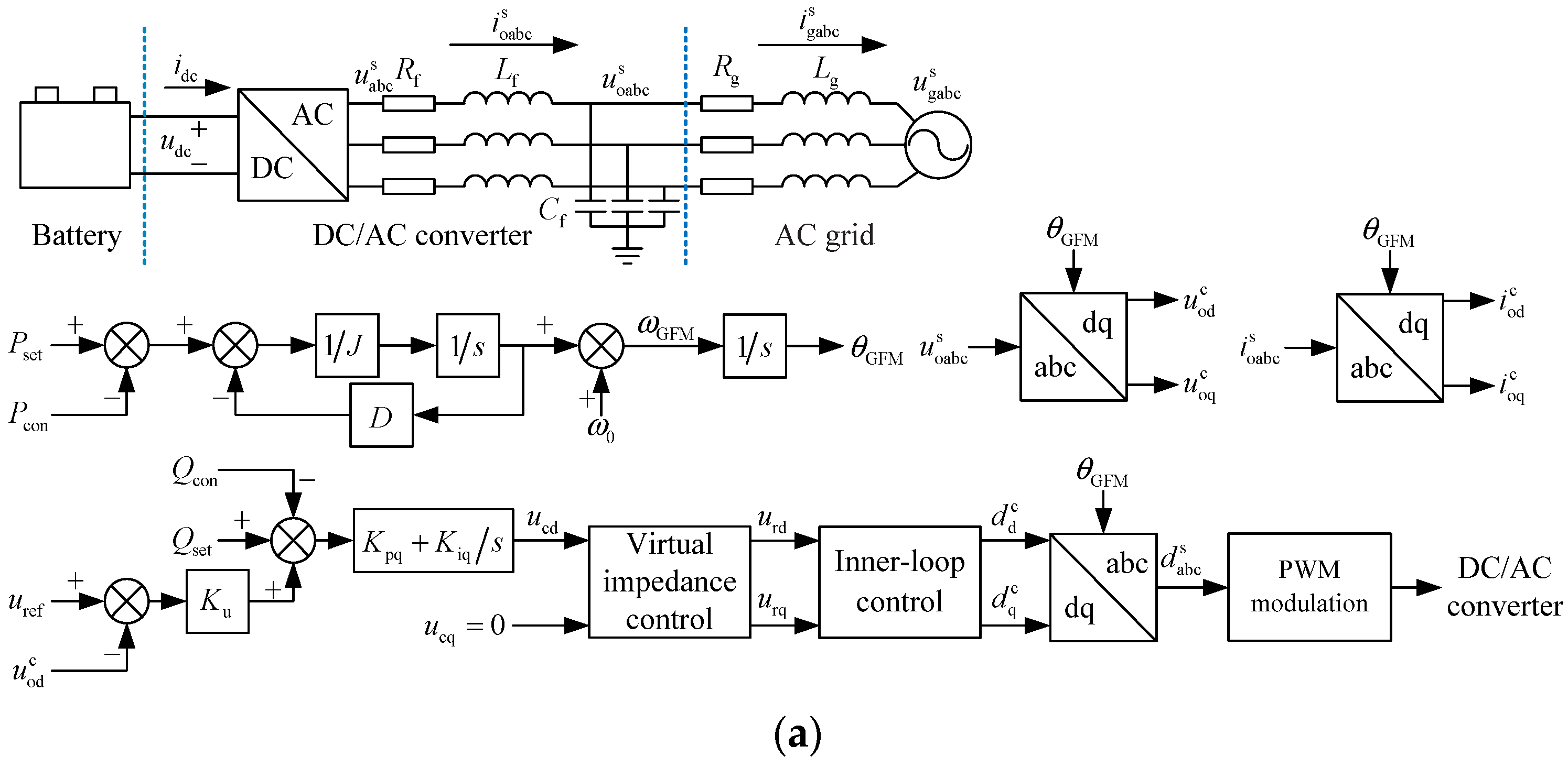
2. A Glimpse of the GFM Energy Storage Grid-Connected System

Figure 1 shows the circuit topology and control block diagram of the GFM energy storage grid-connected system, where L f and R f are the filter inductance and parasitic resistance, respectively. C f is the filter capacitor. L g and R g are the equivalent inductance and equivalent resistance of the power grid, respectively. u dc is the DC voltage. i dc is the DC current. u abc s is the converter bridge arm voltage. i oabc s is the converter output current. u oabc s is the converter output voltage. i gabc s is the converter grid-connection current. u gabc s is the grid equivalent voltage. P set and P con are the set value and measured value of the active power of the GFM energy storage, respectively. ω GFM is the output angular velocity of the GFM control, and ω 0 is the rating of the angular velocity. θ GFM is the output phase angle of the GFM control. Variables in the control coordinate system and system coordinate system are distinguished by superscripts. The superscript c represents the component of the variable in the control coordinate system, and the superscript s represents the component of the variable in the system coordinate system. u od c and u oq c are the dq-axis components of u oabc s in the GFM control coordinate system, and i od c and i oq c are the dq-axis components of i oabc s in the GFM control coordinate system, respectively. Q set and Q con are the set value and measured value of the GFM energy storage reactive power. u ref is the voltage reference. u cd , u cq , u rd , and u rq are control process variables. d abc s is the system duty cycle, and d d c and d q c are the dq-axis components of d abc s . J and D are the virtual rotational inertia coefficient and damping coefficient. K u is the voltage droop coefficient. K pq and K iq are the proportional and integral parameters of the reactive loop PI controller. R V and L V are the virtual resistance and the virtual inductance of the virtual impedance control. K po and K io are the proportional and integral parameters of the voltage control loop PI controller in the inner loop control, K pi and K ii are the proportional and integral parameters of the current control loop PI controller. s is the Laplacian. There is usually a phase difference between the control coordinate system and the system coordinate system due to some factors such as control delay, as shown in Figure 2, where X represents a certain variable.

3. Low-Frequency Oscillation Stability Analysis of the GFM Energy Storage Grid-Connected System

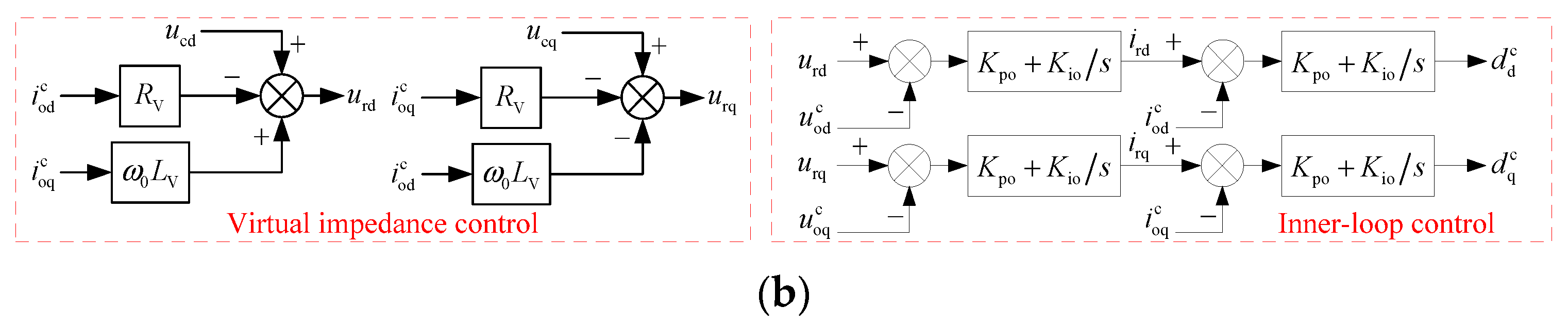
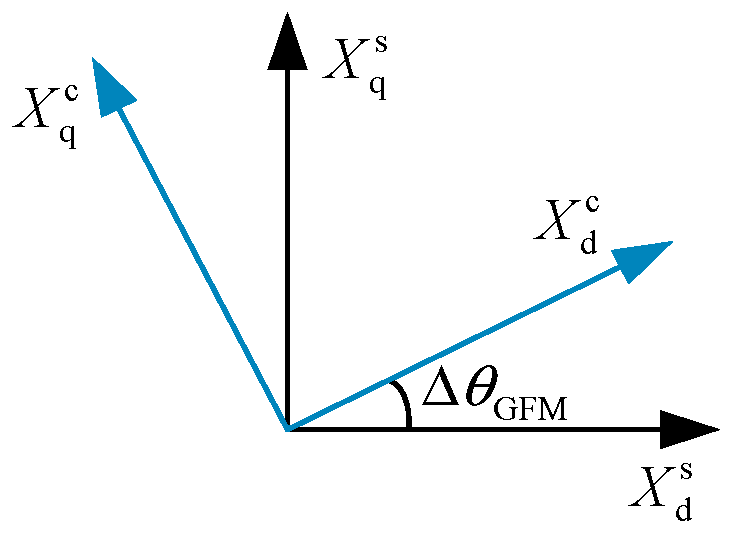
3.1. State-Space Small-Signal Mathematical Modeling of the GFM Energy Storage Grid-Connected System

The mathematical model of the circuit topology of the GFM energy storage grid-connected system can be obtained according to Kirchhoff’s voltage and current laws, as shown in (1) to (5) [37], where S abc s is the switching function [38].
i oabc s = C f d u oabc s d t + i gabc s
u abc s = u oabc s + R f i oabc s + L f d i oabc s d t
u oabc s = u gabc s + R g i gabc s + L g d i gabc s d t
u abc s = 1 3 2 1 1 1 2 1 1 1 2 S abc s u dc
S = 1 , Upper   bridge   arm   conduction S = 0 , Lower   bridge   arm   conduction
The conversion equation from the three-phase stationary coordinate system to the two-phase rotating coordinate system is shown in (6) [39].
T abc / dq θ GFM = 2 3 sin θ GFM sin θ GFM 2 π / 3 sin θ GFM + 2 π / 3 cos θ GFM cos θ GFM 2 π / 3 cos θ GFM + 2 π / 3
Accordingly,
u odq s = T abc / dq θ GFM u oabc s
i odq s = T abc / dq θ GFM i oabc s
u gdq s = T abc / dq θ GFM u gabc s
i gdq s = T abc / dq θ GFM i gabc s
d dq s S dq s = T abc / dq θ GFM S abc s
where
u odq s = u od s u oq s
The other variables have the same equivalence rules as (12).
Equations (7) to (11) are substituted into (1) to (4), and the small-signal mathematical model of the GFM energy storage grid-connected system circuit part is built as shown in (13) to (18) where the subscript 0 represents the steady state value of the variable, and represents the small-signal of the variable around the steady state value.
d u od s d t = 1 C f i od s + ω 0 u oq s 1 C f i gd s
d u oq s d t = 1 C f i oq s ω 0 u od s 1 C f i gq s
d i od s d t = u dc 0 L f d d s 1 L f u od s R f L f i od s + ω 0 i oq s
d i oq s d t = u dc 0 L f d q s 1 L f u oq s R f L f i oq s ω 0 i od s
d i gd s d t = 1 L g u od s R g L g i gd s + ω 0 i gq s
d i gq s d t = 1 L g u oq s ω 0 i gd s R g L g i gq s
The mathematical model of the GFM energy storage control part is obtained from Figure 1, as shown in (19) to (22).
ω GFM = 1 J s + D P set P con + ω 0
θ GFM = 1 s ω GFM
d d c = K u u ref u od c + Q set Q con K pq + K iq s R V i od c + ω 0 L V i oq c u od c K po + K io s i od c K pi + K ii s
d q c = u cq R V i oq c ω 0 L V i od c u oq c K po + K io s i oq c K pi + K ii s
The small-signal mathematical model of the GFM energy storage control part is built according to (19) to (22), as shown in (23) to (26).
d ω GFM d t = 1 J P con D J ω GFM
d θ GFM d t = ω GFM
d d c = K u u od c Q con K pq + K iq s R V i od c + ω 0 L V i oq c u od c K po + K io s i od c K pi + K ii s
d q c = R V i oq c ω 0 L V i od c u oq c K po + K io s i oq c K pi + K ii s
Setting:
d z 1 d t = K u u od c Q con = z 1 s
Equation (28) can be obtained by bringing (27) into (25).
d d c = K pq K u u od c K pq Q con + K iq z 1 R V i od c + ω 0 L V i oq c u od c K po + K io s i od c K pi + K ii s
Setting:
d z 2 d t = K pq K u + 1 u od c K pq Q con + K iq z 1 R V i od c + ω 0 L V i oq c = z 2 s
Equation (30) can be obtained by bringing (29) into (28).
d d c = K po K pq K u + 1 u od c K po K pq Q con + K po K iq z 1 K po R V + 1 i od c + K po ω 0 L V i oq c + K io z 2 K pi + K ii s
Setting:
d z 3 d t = K po K pq K u + 1 u od c K po K pq Q con + K po K iq z 1 K po R V + 1 i od c + K po ω 0 L V i oq c + K io z 2 = z 3 s
Equation (32) can be obtained by bringing (31) into (30).
d d c = K pi K po K pq K u + 1 u od c K pi K po K pq Q con + K pi K po K iq z 1 K pi K po R V + 1 i od c + K pi K po ω 0 L V i oq c + K pi K io z 2 + K ii z 3
Setting:
d z 4 d t = R V i oq c ω 0 L V i od c u oq c = z 4 s
Equation (34) can be obtained by bringing (33) into (26).
d q c = K po R V + 1 i oq c K po ω 0 L V i od c K po u oq c + K io z 4 K pi + K ii s
Setting:
d z 5 d t = K po R V + 1 i oq c K po ω 0 L V i od c K po u oq c + K io z 4 = z 5 s
Equation (36) can be obtained by bringing (35) into (34).
d q c = K pi K po R V + 1 i oq c K pi K po ω 0 L V i od c K pi K po u oq c + K pi K io z 4 + K ii z 5
The conversion equation from the system coordinate system to the control coordinate system is shown in (37) according to Figure 2.
X d c X q c = cos θ GFM sin θ GFM sin θ GFM cos θ GFM X d s X q s
Since θ GFM is smaller, there are cos θ GFM 1 and sin θ GFM θ GFM [40]. Equation (38) to (40) can be obtained by linearizing (37) [41].
d d c d q c = d d s + d q 0 s θ GFM d q s d d 0 s θ GFM
u od c u oq c = u od s + u oq 0 s θ GFM u oq s u od 0 s θ GFM
i od c i oq c = i od s + i oq 0 s θ GFM i oq s i od 0 s θ GFM
The small-signal power model of the GFM energy storage is shown in (41) [42].
P con = u od 0 i od s + u oq 0 i oq s + i od 0 u od s + i oq 0 u oq s Q con = u oq 0 i od s u od 0 i oq s i oq 0 u od s + i od 0 u oq s
Therefore, the state-space small-signal mathematical model of the GFM energy storage grid-connected system can be obtained by associating (13) to (18), (23) to (24), (27), (29), (31) to (33), (35) to (36), and (38) to (41), as shown in (42).
X = A X
where the form of the state variable X is shown in (43).
X = i od s i oq s i gd s i gq s u od s u oq s ω GFM θ GFM z 1 z 2 z 3 z 4 z 5 T
A matrix is the 13 × 13 order state parameter matrix. The detailed form of the A is shown in Appendix A.

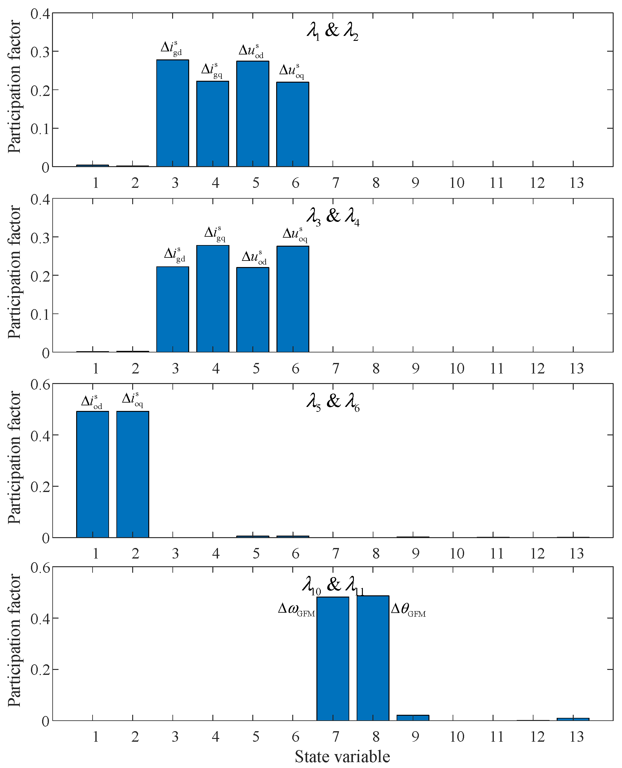
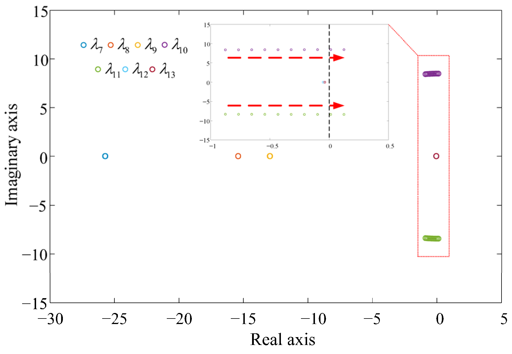
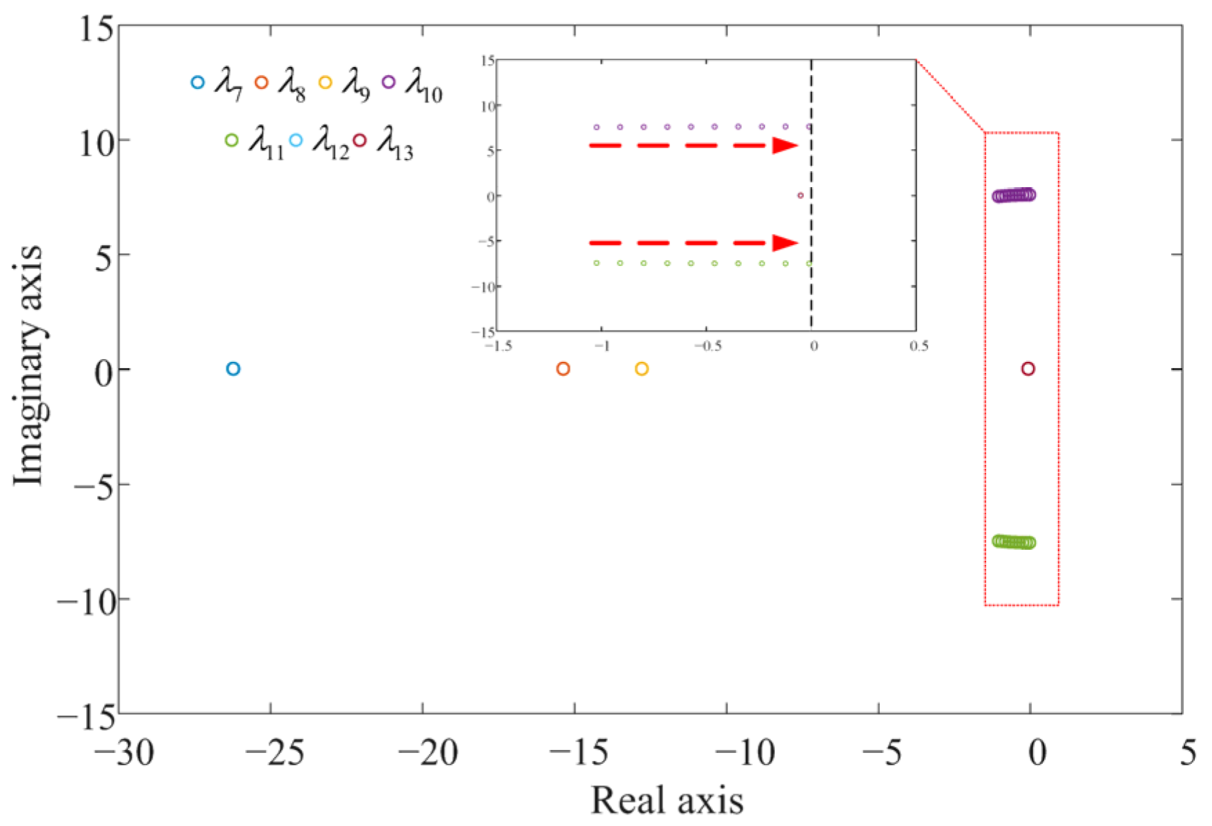
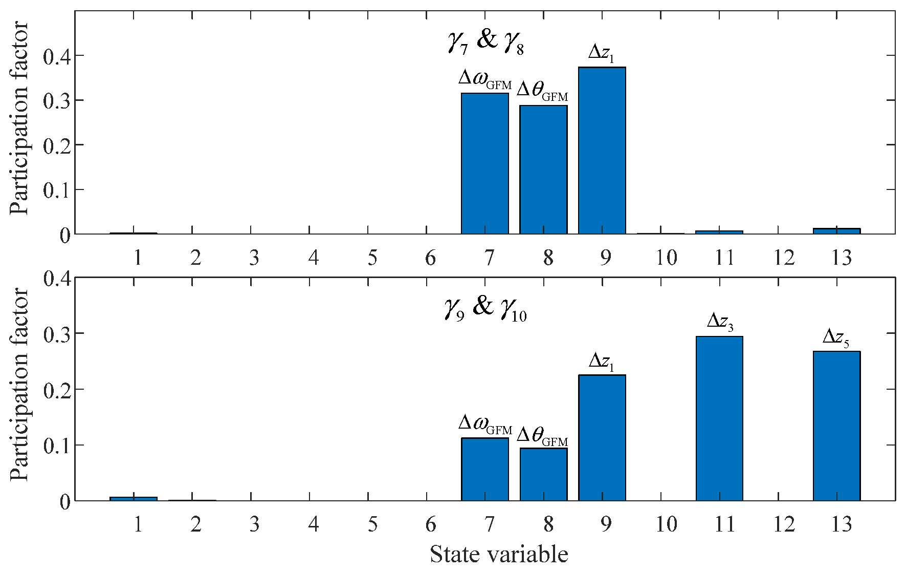
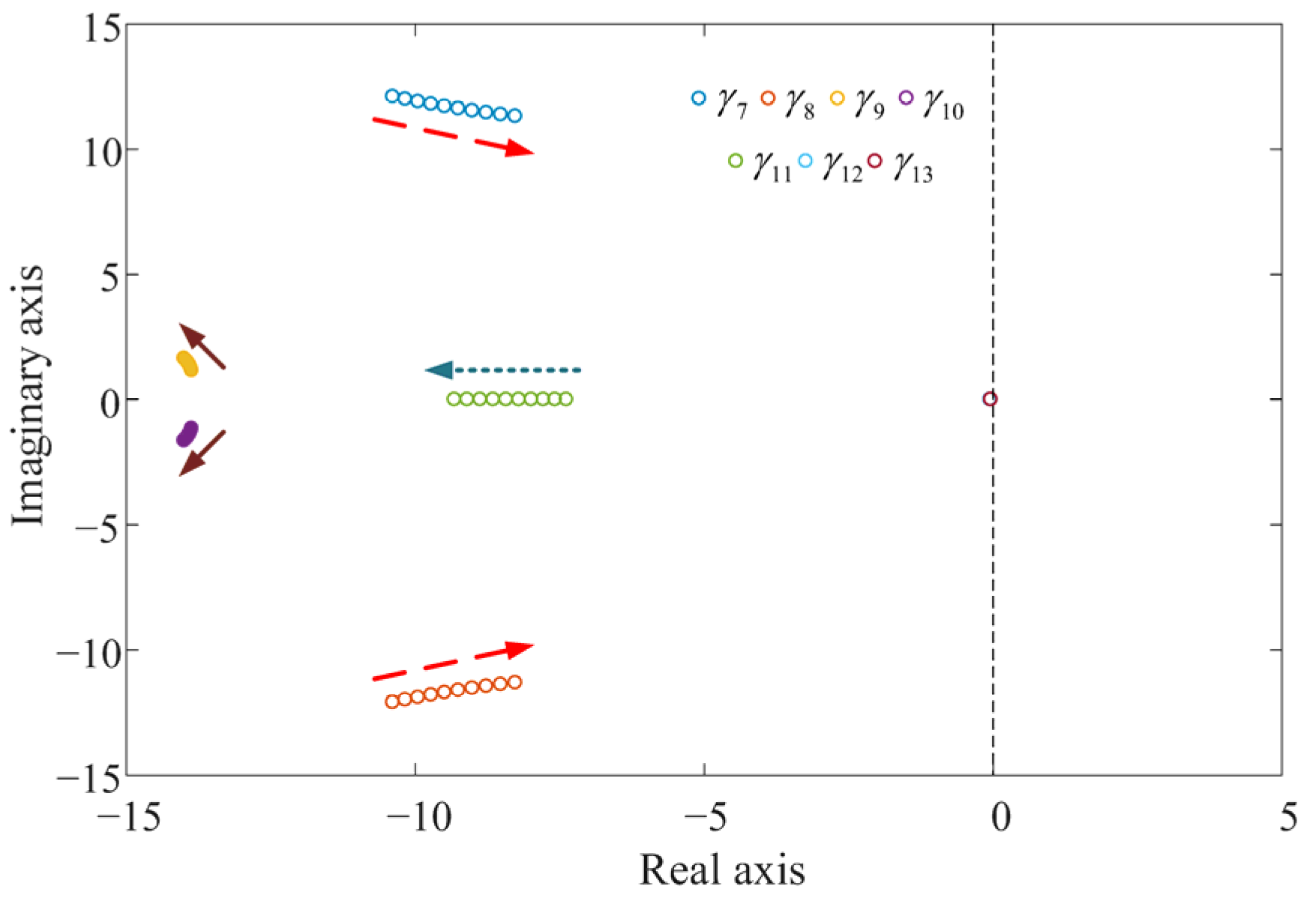
3.2. Mode Analysis of the GFM Energy Storage Grid-Connected System

The basic parameters of the GFM energy storage grid-connected system are shown in Table 2.
Adopting the parameters in Table 2 and setting P set = 1   p . u . and Q set = 0   p . u . , the eigenvalues and oscillation modes of the GFM energy storage grid-connected system are shown in Table 3.
Table 3 shows that there are four oscillation modes in the GFM energy storage grid-connected system. The oscillation modes corresponding to λ 1   &   λ 2 , λ 3   &   λ 4 , and λ 5   &   λ 6 are all high frequency. The oscillation mode corresponding to λ 10   &   λ 11 is low frequency. The participation factors of the state variables for each system oscillation mode are shown in Figure 3.
Figure 3 shows that λ 1   &   λ 2 and λ 3   &   λ 4 are mainly related to i gd s , i gq s , u od s , and u oq s , and are mainly affected by power grid impedance and filter parameters. λ 5   &   λ 6 is mainly related to i od s and i oq s , and is mainly affected by filter parameters and GFM energy storage output power. Comparatively, λ 1   &   λ 2 , λ 3   &   λ 4 , and λ 5   &   λ 6 are farther away from the imaginary axis and have less impact on the stability of the GFM energy storage grid-connected system. λ 10   &   λ 11 is mainly related to ω GFM and θ GFM , and it can be seen from Figure 1 that λ 10   &   λ 11 is mainly affected by the active power loop control parameters of the GFM energy storage. Since λ 10   &   λ 11 is closer to the imaginary axis, the corresponding oscillation mode has a greater impact on the stability of the GFM energy storage grid-connected system.
Setting P set = 1   p . u . and Q set = 0   p . u . , and the parameter D decreases from 0.1 to 0.01 in steps of 0.01, the positions of λ 7 to λ 13 in the complex plane change as shown in Figure 4.
Figure 4 shows that when the parameter D changes, the positions of λ 7 to λ 9 and λ 12 to λ 13 almost do not change. Comparatively, λ 10   &   λ 11 moves from the left half of the complex plane to the right half of the complex plane, which indicates that the GFM energy storage grid-connected system changes from the steady state to the low-frequency oscillation state. As shown from the above analysis results, the parameter D is closely related to the stability of the low-frequency oscillation of the GFM energy storage grid-connected system, and the stability of the GFM energy storage is poorer as the parameter D is smaller. The system is prone to exhibiting a low-frequency oscillation phenomenon when the parameter D is not set properly.
Setting P set = 0.5   p . u . and Q set = 0   p . u . , and the parameter D decreases from 0.1 to 0.01 in steps of 0.01, the positions of λ 7 to λ 13 in the complex plane change as shown in Figure 5.
Figure 5 shows that when the output active power of the GFM energy storage is 0.5 p.u., the GFM energy storage can still operate stably, although the parameter D is reduced to 0.01. Therefore, the smaller the output active power of the GFM energy storage, the better the stability of the GFM energy storage.
Setting P set = 1   p . u . and Q set = 0   p . u . , and the parameter J increases from 0.2 to 0.3 in steps of 0.01, the positions of λ 7 to λ 13 in the complex plane change as shown in Figure 6.
Figure 6 shows that as the parameter J increases, the positions of λ 7 to λ 9 and λ 12 to λ 13 almost do not change, and λ 10   &   λ 11 moves closer to the imaginary axis. Therefore, the stability of the GFM energy storage grid-connected system becomes poor with the increase in the parameter J .
Although the stability of the GFM grid-connected system can be improved by changing the parameters D and J , the parameters D and J are closely related to the inertial response of the GFM energy storage. The dynamics of the GFM energy storage could be affected by arbitrarily adjusting parameter D and parameter J , and these adjustments are difficult to implement in reality. Thus, the new control method should be adopted to improve the ability of the GFM energy storage to suppress low-frequency oscillations.
The above research results show that the low-frequency oscillation stability of the GFM energy storage system is closely related to parameters D and J , and adjusting the damping coefficient value can prevent the GFM energy storage system from experiencing low-frequency oscillations. However, the damping coefficient is related to the dynamic characteristics of the GFM energy storage system. In fact, once this parameter is set by the manufacturer, it will rarely be adjusted. Therefore, it is practically impossible to avoid low-frequency oscillations in GFM energy storage by adjusting control parameters.

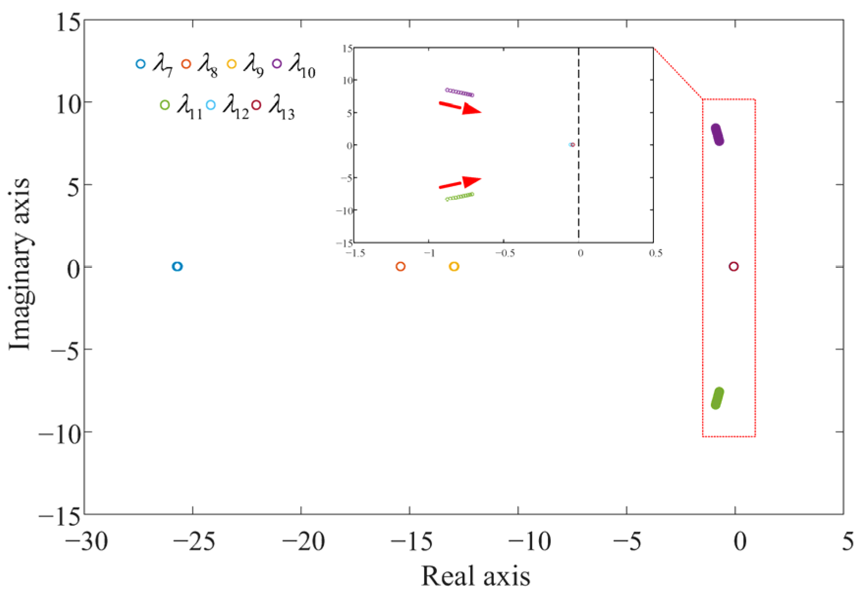
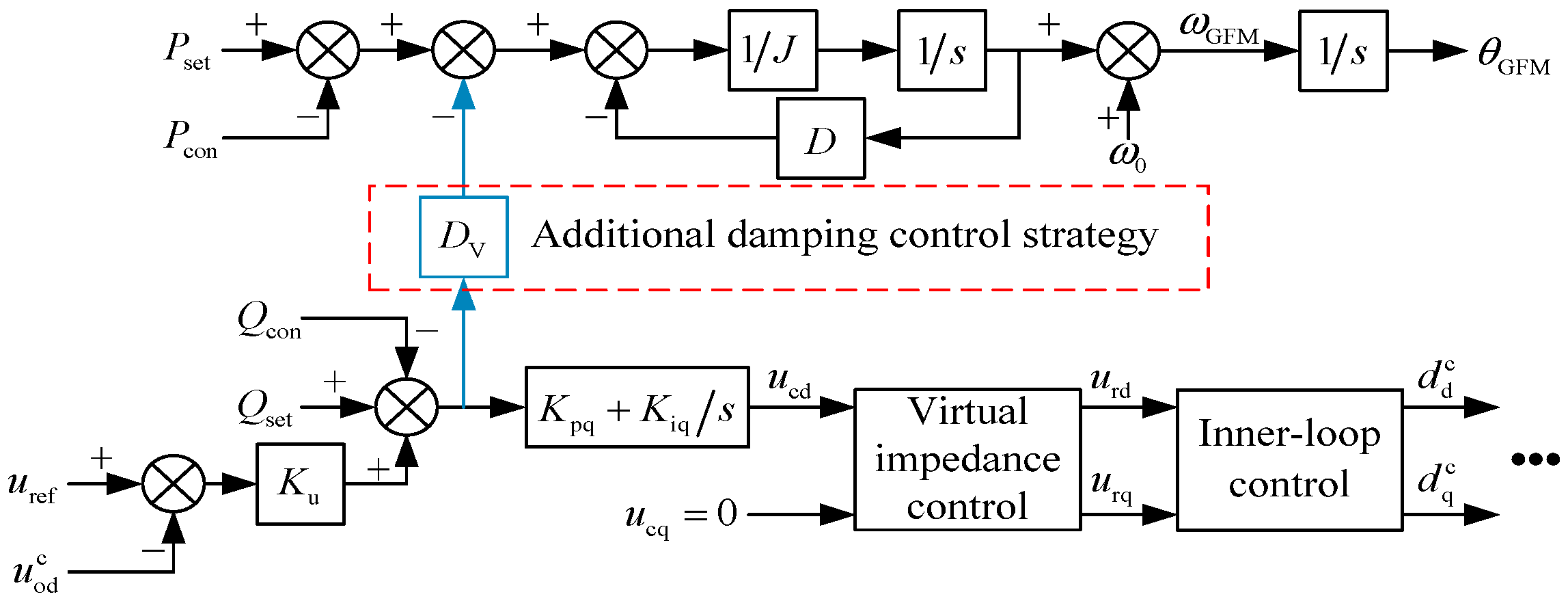
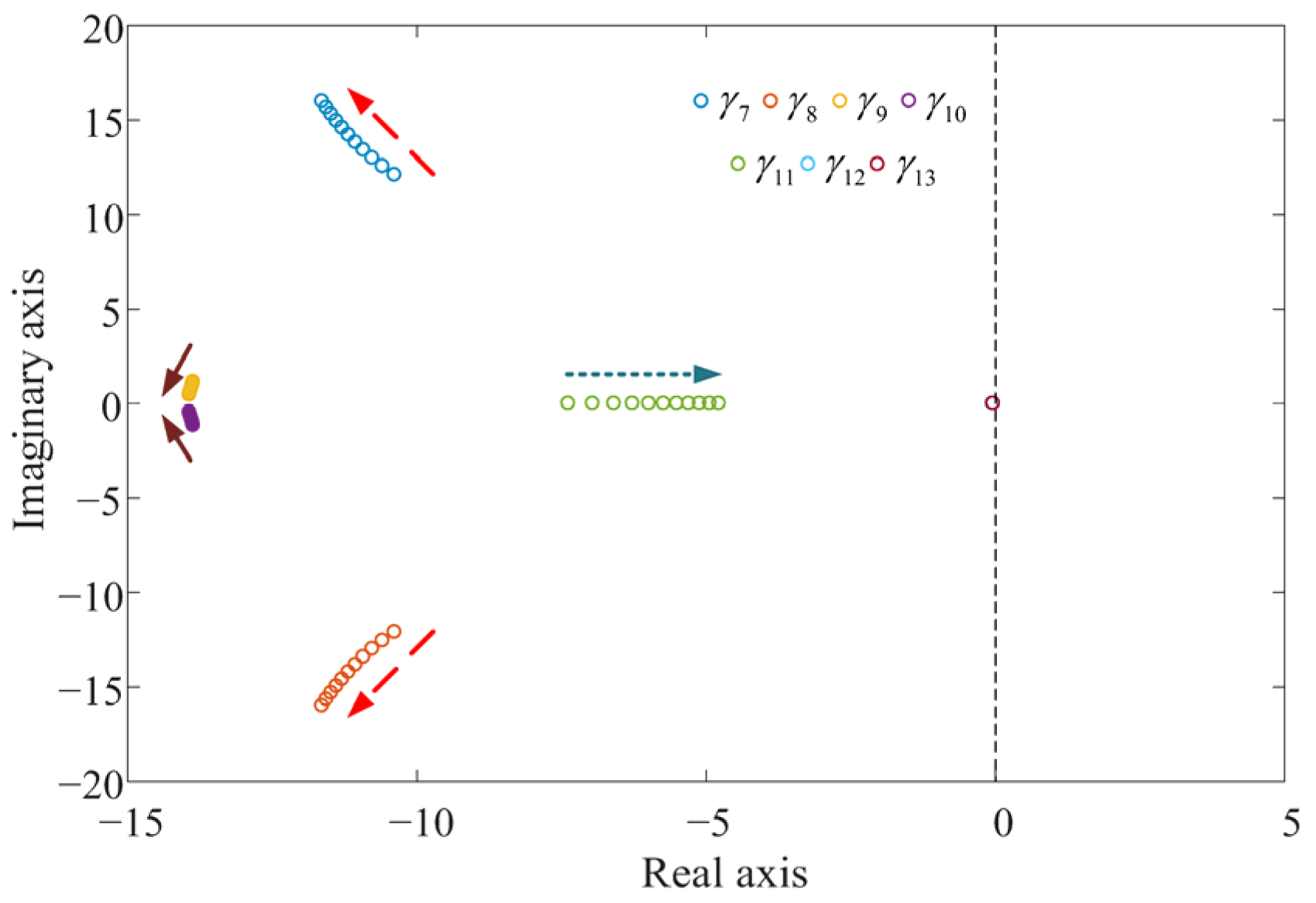
4. Additional Damping Control Strategy for the GFM Energy Storage

This paper proposes an additional damping control strategy for the GFM energy storage to improve the ability of suppressing low-frequency oscillations based on the control strategy shown in Figure 1, as shown in Figure 7. As shown in Figure 7, the proposed control strategy has a simple structure and is easy to implement.
Equation (19) converts to (44) after adopting the additional damping control strategy.
ω GFM = 1 J s + D P set P con D V K u u ref u od c + Q set Q con + ω 0
The small-signal model of (44) is shown in (45).
d ω GFM d t = 1 J P con D J ω GFM + D V K u J u od c + D V J Q con
The parameters are the same as those in Table 2, and P set = 1   p . u . , Q set = 0   p . u . , and D V = 30 . The eigenvalues and oscillation modes of the improved GFM energy storage grid-connected system are shown in Table 4.
It can be seen that γ 1   &   γ 2 , γ 3   &   γ 4 , and γ 5   &   γ 6 correspond to λ 1   &   λ 2 , λ 3   &   λ 4 , and λ 5   &   λ 6 by comparing Table 3 and Table 4, and the eigenvalues are almost unchanged. However, the number of oscillation modes of the GFM energy storage grid-connected system is increased. The participation factors of γ 7   &   γ 8 and γ 9   &   γ 10 are shown in Figure 8.
Figure 8 shows that γ 7   &   γ 8 is mainly related to ω GFM , θ GFM , and Z 1 . γ 7   &   γ 8 is mainly affected by the active power loop control parameters of the GFM energy storage, as shown in Figure 7. This indicates that the oscillation mode corresponding to γ 7   &   γ 8 is consistent with the oscillation mode corresponding to λ 10   &   λ 11 before the improvement. Comparison of Table 3 and Table 4 shows that the distance between γ 7   &   γ 8 and the imaginary axis is substantially larger than the distance between λ 10   &   λ 11 and the imaginary axis before the improvement, and the damping ratio of the oscillation mode corresponding to γ 7   &   γ 8 grows from the original 0.10 to 0.65. The possibility of the oscillation instability of this oscillation mode is greatly decreased, and the stability of the GFM energy storage grid-connected system is significantly improved.
γ 9   &   γ 10 is the new oscillation mode after adopting the additional damping control strategy. Figure 8 shows that γ 9   &   γ 10 is mainly related to ω GFM , θ GFM , Z 1 , Z 3 , and Z 5 , i.e., γ 9   &   γ 10 is mainly affected by the active power loop control parameters and the current inner loop control parameters. The damping ratio of the oscillation mode corresponding to γ 9   &   γ 10 is 1.00, which indicates that the oscillation mode hardly causes oscillation and instability.
Setting P set = 1   p . u . and Q set = 0   p . u . , and the parameter D decreases from 0.1 to 0.01 in steps of 0.01, the position of γ 7 to γ 13 in the complex plane after adopting the additional damping control strategy is shown in Figure 9.
It can be seen from Figure 9 that although γ 7   &   γ 8 moves toward the direction of the imaginary axis as the parameter D decreases, γ 7   &   γ 8 is still in the negative half-plane when D = 0.01 after adopting the additional damping control strategy, and the GFM energy storage grid-connected system can still operate steadily. It indicates that the additional damping control strategy enhances the ability of the GFM energy storage to suppress low-frequency oscillations and improves the stability of the GFM grid-connected system.
Setting P set = 1   p . u . and Q set = 0   p . u . , and the parameter D V increases from 30 to 40 in steps of 1, the position of γ 7 to γ 13 in the complex plane after adopting the additional damping control strategy is shown in Figure 10.
Figure 10 shows that as the parameter D V increases, the positions of γ 9   &   γ 10 , γ 12 , and γ 13 remain almost unchanged. γ 7   &   γ 8 gradually moves away from the virtual axis, which indicates that the ability of GFM to suppress low-frequency oscillations is enhanced. However, γ 11 is close to the virtual axis, which causes the overall stability of the GFM energy storage system to decline. Comprehensively, this paper sets D V = 30 .

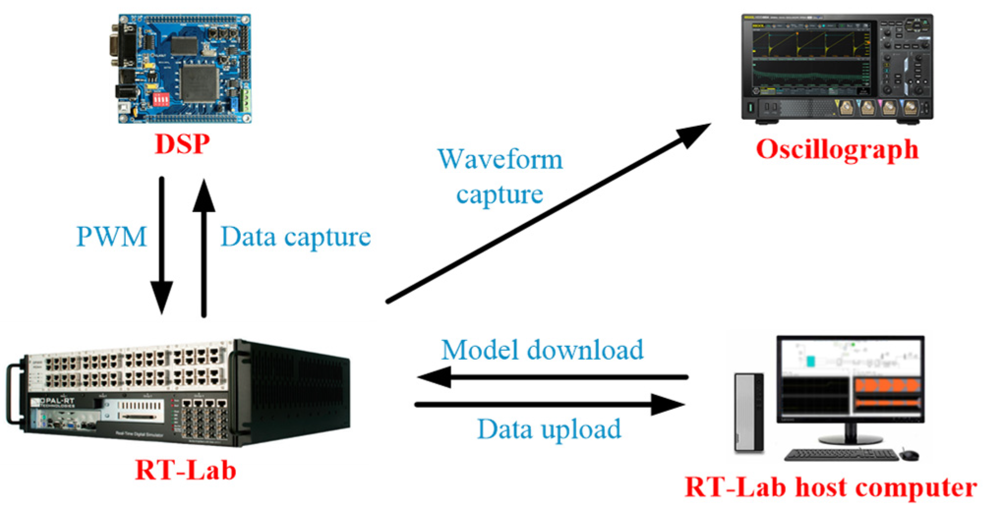
5. Semi-Physical Experiment Verification

To verify the effectiveness of the additional damping control strategy proposed in this paper, this paper develops the semi-physical experiment platform based on the RT-LAB, and the structure is shown in Figure 11. The structure of the GFM energy storage grid-connected system is consistent with Figure 1, and the system parameters are in Table 2. The DSP implements the GFM control strategy of the GFM energy storage, and the RT-LAB implements the other parts of the GFM energy storage grid-connected system. It should be noted that the origin of the coordinate system in the experiment results is considered to be the time zero point.
P set is set to step from 0.5 p.u. to 1 p.u. at 0.5 s, and Q set = 0   p . u . and J = 0.2 . The parameter D is set equal to 0.1, 0.05, and 0.01, and the output power of the GFM energy storage is shown in Figure 12. The corresponding phase A current is shown as Figure A1 in Appendix B.
Figure 12 shows that the overshoot of the output power of the GFM energy storage becomes larger and the regulation time becomes longer as the parameter D decreases, which indicates that its stability becomes worse. Especially, the GFM energy storage occurs power low-frequency oscillation when D = 0.01 , and the oscillation frequency is 1.5 Hz, as shown in Figure A2 in Appendix B. The oscillation frequency is consistent with the oscillation frequency of the oscillation mode corresponding to λ 10   &   λ 11 in Table 3, which proves the correctness of the state-space small-signal mathematical model of the GFM energy storage grid-connected system built in this paper.
P set is set to step from 0.5 p.u. to 1 p.u. at 0.5 s, and Q set = 0   p . u . and D = 0.1 . The parameter J is set equal to 0.2, 0.25, and 0.3, and the output power of the GFM energy storage is shown in Figure 13.
Figure 13 shows that as the parameter J increases, the output power overshoot of the GFM energy storage increases and the regulation time becomes longer. The stability deterioration of the GFM energy storage verifies the effect of the parameter J on the stability of the GFM energy storage.
P set is set to step from 0.5 p.u. to 1 p.u. at 0.5 s, and Q set = 0   p . u . , J = 0.2 , and D = 0.01 . The additional damping control strategy is accessed at 1.5 s, and the output power of the GFM energy storage is shown in Figure 14.
It can be seen from Figure 14 that the GFM energy storage grid-connected system causes power low-frequency oscillations when the parameter D is small, similar to Figure 12. Especially, the GFM energy storage can immediately transform from the oscillation destabilization state to the stable operation state when the additional damping control strategy is accessed. The experiment results verify that the additional damping control strategy improves the ability of the GFM energy storage to suppress low-frequency oscillations and improves the stability of the GFM energy storage grid-connected system.
To verify the adaptability of the proposed additional damping control strategy to different grid conditions, this paper sets the GFM energy storage to operate in the strong and weak grid, inductive and resistive grid, voltage sag grid, and frequency deviation grid [1]. The experiment results are shown in Appendix C. The experiment results show that the GFM energy storage system with an additional damping control strategy can operate smoothly in different grid conditions. Therefore, the proposed additional damping control strategy has strong adaptability to different grid conditions.

6. Conclusions

This paper analyses the low-frequency oscillation problem of the GFM energy storage grid-connected system via the state-space small-signal mathematical modeling of the GFM energy storage. The research results indicate that the key parameter affecting the GFM energy storage to cause low-frequency oscillations is the damping coefficient of the GFM control. Although adjusting the value of the damping coefficient can avoid low-frequency oscillations of the GFM energy storage, the variation in the damping coefficient would affect the dynamic characteristics of the GFM energy storage at the same time. Therefore, this paper proposes an additional damping control strategy. The proposed control strategy can increase the damping ratio of the low-frequency oscillation mode of the GFM energy storage grid-connected system and improve the stability of the GFM energy storage, and thus, the low-frequency oscillation of the GFM energy storage grid-connected system is avoided. The semi-physical experiment results prove that the additional damping control strategy proposed in this paper can make the GFM energy storage grid-connected system, which has already experienced low-frequency oscillations, recover to a stable operation state. The additional damping control strategy significantly improves the stability of the GFM energy storage. In addition, the proposed control strategy has strong adaptability to different grid conditions.
Obviously, this paper only proves the effectiveness of the proposed additional damping control strategy based on an eigenvalue analysis, without analyzing the interaction mechanism between the active power loop and the reactive power loop to explain the working principle of the proposed control strategy. Therefore, we will utilize amplitude–phase dynamics to analyze the effect path and mechanism of the additional damping control strategy in future research and provide new solutions for GFM control damping enhancement methods.

Author Contributions

Conceptualization, C.T. and J.X.; methodology, X.L.; software, G.Y.; validation, G.Y. and W.C.; formal analysis, J.X.; investigation, X.L.; resources, C.T.; data curation, G.Y.; writing—original draft preparation, C.T.; writing—review and editing, C.T. and J.X.; visualization, W.C.; supervision, X.L.; project administration, J.X.; funding acquisition, J.X. All authors have read and agreed to the published version of the manuscript.

Funding

This research received no external funding.

Data Availability Statement

No data was used for the research described in the article.

Acknowledgments

This work was supported by the National Natural Science Foundation of China under Grant 51777130.

Conflicts of Interest

The authors declare no conflicts of interest. The funders had no role in the design of the study; in the collection, analyses, or interpretation of data; in the writing of the manuscript; or in the decision to publish the results.

Appendix A

The detailed form of A .
A = K 1 _ 1 K 1 _ 2 0 0 K 1 _ 5 K 1 _ 6 0 K 1 _ 8 K 1 _ 9 K 1 _ 10 K 1 _ 11 0 0 K 2 _ 1 K 2 _ 2 0 0 0 K 2 _ 6 0 K 2 _ 8 0 0 0 K 2 _ 12 K 2 _ 13 0 0 K 3 _ 3 K 3 _ 4 K 3 _ 5 0 0 0 0 0 0 0 0 0 0 K 4 _ 3 K 4 _ 4 0 K 4 _ 6 0 0 0 0 0 0 0 K 5 _ 1 0 K 5 _ 3 0 0 K 5 _ 6 0 0 0 0 0 0 0 0 K 6 _ 2 0 K 6 _ 4 K 6 _ 5 0 0 0 0 0 0 0 0 K 7 _ 1 K 7 _ 2 0 0 K 7 _ 5 K 7 _ 6 K 7 _ 7 0 0 0 0 0 0 0 0 0 0 0 0 K 8 _ 7 0 0 0 0 0 0 K 9 _ 1 K 9 _ 2 0 0 K 9 _ 5 K 9 _ 6 0 K 9 _ 8 0 0 0 0 0 K 10 _ 1 K 10 _ 0 0 K 10 _ 5 K 10 _ 6 0 K 10 _ 8 K 10 _ 9 0 0 0 0 K 11 _ 1 K 11 _ 2 0 0 K 11 _ 5 K 11 _ 6 0 K 11 _ 8 K 11 _ 9 K 11 _ 10 0 0 0 K 12 _ 1 K 12 _ 2 0 0 0 K 12 _ 6 0 K 12 _ 8 0 0 0 0 0 K 13 _ 1 K 13 _ 2 0 0 0 K 13 _ 6 0 K 13 _ 8 0 0 0 K 13 _ 12 0
K 1 _ 1 = u dc 0 L f K pi K po K pq u oq 0 + K pi K po R V + 1 + R f L f K 1 _ 2 = ω 0 + u dc 0 L f K pi K po K pq u od 0 + K pi K po ω 0 L V K 1 _ 5 = u dc 0 L f K pi K po K pq i oq 0 K pi K po K pq K u + 1 1 L f K 1 _ 6 = u dc 0 K pi K po K pq i od 0 L f K 1 _ 8 = u dc 0 L f K pi K po K pq K u + 1 u oq 0 s + K pi K po R V + 1 i oq 0 s + K pi K po ω 0 L V i od 0 s + d q 0 s K 1 _ 9 = u dc 0 K pi K po K iq L f K 1 _ 10 = u dc 0 K pi K io L f K 1 _ 11 = u dc 0 K ii L f
K 2 _ 1 = ω 0 + u dc 0 K pi K po ω 0 L V L f K 2 _ 2 = R f L f + u dc 0 K pi K po R V + 1 L f K 2 _ 6 = 1 L f + u dc 0 K pi K po L f K 2 _ 8 = u dc 0 L f K pi K po R V + 1 i od 0 s K pi K po ω 0 L V i oq 0 s + K pi K po u od 0 s + d d 0 s K 2 _ 12 = u dc 0 K pi K io L f K 2 _ 13 = u dc 0 K ii L f
K 3 _ 3 = R g L g K 3 _ 4 = ω 0 K 3 _ 5 = 1 L g
K 4 _ 3 = ω 0 K 4 _ 4 = R g L g K 4 _ 6 = 1 L g
K 5 _ 1 = 1 C f K 5 _ 3 = 1 C f K 5 _ 6 = ω 0
K 6 _ 2 = 1 C f K 6 _ 4 = 1 C f K 6 _ 5 = ω 0
K 7 _ 1 = 1 J u od 0 K 7 _ 2 = 1 J u oq 0 K 7 _ 5 = 1 J i od 0 K 7 _ 6 = 1 J i oq 0 K 7 _ 7 = D J
K 8 _ 7 = 1
K 9 _ 1 = u oq 0 K 9 _ 2 = u od 0 K 9 _ 5 = i oq 0 K u K 9 _ 6 = i od 0 K 9 _ 8 = K u u oq 0 s
K 10 _ 1 = K pq u oq 0 + R V K 10 _ 2 = K pq u od 0 + ω 0 L V K 10 _ 5 = K pq i oq 0 K pq K u + 1 K 10 _ 6 = K pq i od 0 K 10 _ 8 = K pq K u + 1 u oq 0 s + R V i oq 0 s + ω 0 L V i od 0 s K 10 _ 9 = K iq
K 11 _ 1 = K po K pq u oq 0 + K po R V + 1 K 11 _ 2 = K po K pq u od 0 + K po ω 0 L V K 11 _ 5 = K po K pq i oq 0 K po K pq K u + 1 K 11 _ 6 = K po K pq i od 0 K 11 _ 8 = K po K pq K u + 1 u oq 0 s + K po R V + 1 i oq 0 s + K po ω 0 L V i od 0 s K 11 _ 9 = K po K iq K 11 _ 10 = K io
K 12 _ 1 = ω 0 L V K 12 _ 2 = R V K 12 _ 6 = 1 K 12 _ 8 = R V i od 0 s ω 0 L V i oq 0 s + u od 0 s
K 13 _ 1 = K po ω 0 L V K 13 _ 2 = K po R V + 1 K 13 _ 6 = K po K 13 _ 8 = K po R V + 1 i od 0 s K po ω 0 L V i oq 0 s + K po u od 0 s K 13 _ 12 = K io

Appendix B

Figure A1. The corresponding phase A current with different parameters D .
Energies 18 03971 g0a1
Figure A2. The FFT analysis of the GFM energy storage active power.
Energies 18 03971 g0a2

Appendix C

P set is set to step from 0.5 p.u. to 1 p.u. at 0.5 s, and Q set = 0   p . u . , J = 0.2 , D = 0.01 , and D V = 30 . This paper sets SCR = 8, Xg/Rg = 7, SCR = 1.5, Xg/Rg =7, and SCR = 8, Xg/Rg =1, respectively (SCR is the short-circuit ratio, X g = ω 0 L g ), and the output power of the GFM energy storage is shown in Figure A3.
Figure A3. Output power of the GFM energy storage with various grid parameters.
Energies 18 03971 g0a3
P set = 0.5   p . u . , Q set = 0   p . u . , J = 0.2 , D = 0.01 , and D V = 30 . The grid voltage is set to drop from 1 p.u. to 0.5 p.u. at 0.5 s, with a duration of 200 ms. The output power of the GFM energy storage is shown in Figure A4.
Figure A4. Output power of the GFM energy storage with grid voltage sag.
Energies 18 03971 g0a4
P set = 0.5   p . u . , Q set = 0   p . u . , J = 0.2 , D = 0.01 , and D V = 30 . The grid frequency is set to drop from 50 Hz to 49.5 Hz in 0.5 s, and then step from 49.5 Hz to 50 Hz at 1.5 s. The output power of the GFM energy storage is shown in Figure A5.
Figure A5. Output power of the GFM energy storage with grid frequency deviation.
Energies 18 03971 g0a5

References

  1. Mohammed, N.; Udawatte, H.; Zhou, W.; Hill, D.; Bahrani, B. Grid-Forming Inverters: A comparative study of different control strategies in frequency and time domains. IEEE Open J. Ind. Electron. Soc. 2024, 5, 185–214. [Google Scholar] [CrossRef]
  2. Mastoi, M.; Zhuang, S.; Haris, M.; Hassan, M.; Ali, A. Large-scale wind power grid integration challenges and their solution: A detailed review. Environ. Sci. Pollut. Res. 2023, 30, 103424–103462. [Google Scholar] [CrossRef] [PubMed]
  3. Shintai, T.; Miura, Y.; Ise, T. Oscillation damping of a distributed generator using a virtual synchronous generator. IEEE Trans. Power Deliv. 2014, 29, 668–676. [Google Scholar] [CrossRef]
  4. Alawasa, K.; Mohamed, Y.; Xu, W. Active Mitigation of Subsynchronous Interactions Between PWM Voltage-Source Converters and Power Networks. IEEE Trans. Power Electron. 2014, 29, 121–134. [Google Scholar] [CrossRef]
  5. Zhou, J.; Ding, H.; Fan, S.; Zhang, Y.; Gole, A. Impact of Short-Circuit Ratio and Phase-Locked-Loop Parameters on the Small-Signal Behavior of a VSC-HVDC Converter. IEEE Trans. Power Deliv. 2014, 29, 2287–2296. [Google Scholar] [CrossRef]
  6. Yang, D.; Wang, X.; Liu, F.; Xin, K.; Liu, Y.; Blaabjerg, F. Symmetrical PLL for SISO Impedance Modeling and Enhanced Stability in Weak Grids. IEEE Trans. Power Electron. 2020, 35, 1473–1483. [Google Scholar] [CrossRef]
  7. Bahrani, B. Power-Synchronized Grid-Following Inverter Without a Phase-Locked Loop. IEEE Access 2021, 9, 112163–112176. [Google Scholar] [CrossRef]
  8. Mohammed, N.; Ravanji, M.; Zhou, W.; Bahrani, B. Enhanced Frequency Control for Power-Synchronized PLL-Less Grid-Following Inverters. IEEE Open J. Ind. Electron. Soc. 2023, 4, 189–204. [Google Scholar] [CrossRef]
  9. Ndreko, M.; Rüberg, S.; Winter, W. Grid forming control scheme for power systems with up to 100% power electronic interfaced generation: A case study on Great Britain test system. IET Renew. Power Gener. 2020, 14, 1268–1281. [Google Scholar] [CrossRef]
  10. Zhong, Q.; Weiss, G. Synchronverters: Inverters that mimic synchronous generators. IEEE Trans. Ind. Electron. 2011, 58, 1259–1267. [Google Scholar] [CrossRef]
  11. Unruh, P.; Nuschke, M.; Strauss, P.; Welck, F. Overview on grid-forming inverter control methods. Energies 2020, 13, 2589. [Google Scholar] [CrossRef]
  12. Si, W.; Fang, J. Transient stability improvement of grid-forming converters through voltage amplitude regulation and reactive power injection. IEEE Trans. Power Electron. 2023, 38, 12116–12125. [Google Scholar] [CrossRef]
  13. Lu, Y.; Shi, G.; Chen, Q.; Qiu, P.; Zhou, J.; Yang, R.; Zhang, J. Stability analysis and stabilization control of a grid-forming VSC-HVDC system. Front. Energy Res. 2024, 12, 1437287. [Google Scholar] [CrossRef]
  14. Du, W.; Chen, Z.; Schneider, K.; Lasseter, R.; Nandanoori, S.; Tuffner, F.; Kundu, S. A comparative study of two widely used grid-forming droop controls on microgrid small-signal stability. IEEE J. Emerg. Sel. Top. Power Electron. 2020, 8, 963–975. [Google Scholar] [CrossRef]
  15. Lu, M.; Dhople, S.; Johnson, B. Benchmarking nonlinear oscillators for grid-forming inverter control. IEEE Trans. Power Electron. 2022, 37, 10250–10266. [Google Scholar] [CrossRef]
  16. Poolla, B.; Gross, D.; Dörfler, F. Placement and implementation of grid-forming and grid-following virtual inertia and fast frequency response. IEEE Trans. Power Syst. 2019, 34, 3035–3046. [Google Scholar] [CrossRef]
  17. Xiong, X.; Zhou, Y.; Luo, B.; Cheng, P.; Blaabjerg, F. Analysis and suppression strategy of synchronous frequency resonance for grid-connected converters with power-synchronous control method. IEEE Trans. Power Electron. 2023, 38, 6945–6955. [Google Scholar] [CrossRef]
  18. Rathnayake, D.; Razzaghi, R.; Bahrani, B. Generalized virtual synchronous generator control design for renewable power systems. IEEE Trans. Sustain. Energy 2022, 13, 1021–1036. [Google Scholar] [CrossRef]
  19. Mohammed, N.; Ravanji, M.; Zhou, W.; Bahrani, B. Online grid impedance estimation-based adaptive control of virtual synchronous generators considering strong and weak grid conditions. IEEE Trans. Sustain. Energy 2023, 14, 673–687. [Google Scholar] [CrossRef]
  20. Beck, H.; Hesse, R. Virtual synchronous machine. In Proceedings of the 9th International Conference on Electrical Power Quality and Utilisation, Barcelona, Spain, 9–11 October 2007; pp. 1–6. [Google Scholar]
  21. Visscher, K.; Haan, S. Virtual synchronous machines (VSG’S) for frequency stabilization in future grids with a significant share of decentralized generation. In Proceedings of the CIRED Seminar 2008: Smartgrids for Distribution, Frankfurt, Germany, 23–24 June 2008; pp. 1–4. [Google Scholar]
  22. Zhang, H.; Zhou, Y.; He, W.; Hu, J.; Huang, W.; Li, W.; Zhai, S. Mechanism Analysis of low-frequency oscillation caused by VSG from the perspective of vector motion. Processes 2023, 12, 2303. [Google Scholar] [CrossRef]
  23. Ruan, J.; Shi, Z.; Yu, M.; Wang, S. Simplified damping analysis and suppression method for low-frequency oscillation introduced by virtual synchronous generator. J. Power Electron. 2021, 21, 1600–1610. [Google Scholar] [CrossRef]
  24. Shi, Y.; Fang, C.; Chen, L.; Mao, M.; Chen, Z. Inertia parameter selection method for HVDC converter station based on VSG control. J. Electr. Eng. Technol. 2022, 17, 1019–1030. [Google Scholar]
  25. Lu, S.; Wang, T.; Liang, Y.; Cheng, S.; Cai, Y.; Wang, H.; Yang, J.; Sui, Y.; Yang, L. Low-frequency oscillation analysis of grid-connected VSG system considering multi-parameter coupling. Comput. Model. Eng. Sci. 2023, 135, 2373–2386. [Google Scholar] [CrossRef]
  26. Hu, S.; Meng, K.; Wu, Z. A parameter-adaptive method for primary frequency regulation of grid-forming direct-drive wind turbines. Sensors 2024, 24, 6651. [Google Scholar] [CrossRef] [PubMed]
  27. Xiong, K.; Hu, W.; Zhang, G.; Chen, Z. Deep reinforcement learning based parameter self-tuning control strategy for VSG. Energy Rep. 2022, 8, 219–226. [Google Scholar] [CrossRef]
  28. Xu, Q.; Dragicevic, T.; Xie, L.; Blaabjerg, F. Artificial intelligence-based control design for reliable virtual synchronous generators. IEEE Trans. Power Electron. 2021, 36, 9453–9464. [Google Scholar] [CrossRef]
  29. Xiong, X.; Li, X.; Luo, B.; Huang, M.; Zhao, C.; Blaabjerg, F. An additional damping torque method for low-frequency stability enhancement of virtual synchronous generators. IEEE Trans. Power Electron. 2024, 39, 15858–15869. [Google Scholar] [CrossRef]
  30. Wang, H.; Hao, Y.; He, H.; Dong, H.; Lu, S.; Zhang, G.; Yang, J.; Chen, Z. Influence mechanism and virtual power system stabiliser method of virtual synchronous generator for low-frequency oscillation of power system. IET Energy Syst. Integr. 2023, 6, 104–116. [Google Scholar] [CrossRef]
  31. Yang, M.; Wu, X.; Yu, D.; Loveth, M.; Yu, S. An optimized power-angle and excitation dual loop virtual power system stabilizer for enhanced MMC-VSG control and low-frequency oscillation suppression. Energies 2024, 6, 4711. [Google Scholar] [CrossRef]
  32. Liu, J.; Miura, Y.; Ise, T. Fixed-parameter damping methods of virtual synchronous generator control using state feedback. IEEE Access 2024, 7, 99177–99190. [Google Scholar] [CrossRef]
  33. Xiong, X.; Wu, C.; Blaabjerg, F. An improved synchronization stability method of virtual synchronous generators based on frequency feedforward on reactive power control loop. IEEE Trans. Power Electron. 2021, 36, 9136–9148. [Google Scholar] [CrossRef]
  34. Li, C.; Yang, Y.; Mijatovic, N.; Dragicevic, T. Frequency stability assessment of grid-forming VSG in framework of MPME with feedforward decoupling control strategy. IEEE Trans. Ind. Electron. 2022, 69, 6903–6913. [Google Scholar] [CrossRef]
  35. Zhou, W.; Mohammed, N.; Bahrani, B. Comprehensive Modeling, Analysis, and Comparison of State-Space and Admittance Models of PLL-Based Grid-Following Inverters Considering Different Outer Control Modes. IEEE Access 2022, 10, 30109–30146. [Google Scholar] [CrossRef]
  36. Hu, J.; Yuan, H.; Yuan, X. Modeling of DFIG-Based WTs for Small-Signal Stability Analysis in DVC Timescale in Power Electronized Power Systems. IEEE Trans.Energy Conver. 2017, 32, 1151–1165. [Google Scholar] [CrossRef]
  37. Xu, L.; Fan, L.; Miao, Z. DC impedance-model-based resonance analysis of a VSC-HVDC system. IEEE Trans. Power Deliv. 2015, 30, 1221–1230. [Google Scholar] [CrossRef]
  38. Yu, G.; Xu, J.; Wu, G.; Ren, W. Reactive power decoupling control strategy for the grid-forming photovoltaic DC/AC converter. Electr. Power Syst. Res. 2024, 236, 110962. [Google Scholar] [CrossRef]
  39. Cespedes, M.; Sun, J. Impedance modeling and analysis of grid-connected voltage-source converters. IEEE Trans. Power Electron. 2014, 29, 1254–1261. [Google Scholar] [CrossRef]
  40. Yuan, H.; Yuan, X.; Hu, J. Modeling of grid-connected VSCs for power system small-signal stability analysis in DC-Link voltage control timescale. IEEE Trans. Power Syst. 2017, 32, 3981–3991. [Google Scholar] [CrossRef]
  41. Yu, G.; Xu, J.; Yan, Z.; Ren, W. An optimized grid-forming control strategy for the flexible interconnection system in distribution transformer areas. IEEJ Trans. Electr. Electron. Eng. 2024, 19, 1311–1323. [Google Scholar] [CrossRef]
  42. Yu, G.; Xu, J.; Wu, G.; Zhang, Z.; Zhao, D. Improved virtual synchronous generator control strategy for the flexible interconnection system in distribution transformer areas. Electr. Power Syst. Res. 2023, 214, 108877. [Google Scholar] [CrossRef]
Figure 1. The circuit topology and control block diagram of the GFM energy storage grid-connected system: (a) circuit topology and control block diagram; (b) virtual impedance control and inner loop control.
Energies 18 03971 g001aEnergies 18 03971 g001b
Figure 2. Relationship between the control coordinate system and the system coordinate system.
Energies 18 03971 g002
Figure 3. Participating factors of each system oscillation mode.
Energies 18 03971 g003
Figure 4. Positions of λ 7 to λ 13 to λ 13 when parameter D is changed ( P set = 1   p . u . ).
Energies 18 03971 g004
Figure 5. Positions of λ 7 to λ 13 when parameter D is changed ( P set = 0.5   p . u . ).
Energies 18 03971 g005
Figure 6. Positions of λ 7 to λ 13 when parameter J is changed ( P set = 1   p . u . ).
Energies 18 03971 g006
Figure 7. Additional damping control strategy for the GFM energy storage.
Energies 18 03971 g007
Figure 8. Participating factors of γ 7   &   γ 8 and γ 9   &   γ 10 .
Energies 18 03971 g008
Figure 9. Positions of γ 7 to γ 13 when parameter D is changed.
Energies 18 03971 g009
Figure 10. Positions of γ 7 to γ 13 when parameter D V is changed.
Energies 18 03971 g010
Figure 11. The structure of the semi-physical experiment platform.
Energies 18 03971 g011
Figure 12. Output power of the GFM energy storage with different parameters D .
Energies 18 03971 g012
Figure 13. Output power of the GFM energy storage with different parameters J .
Energies 18 03971 g013
Figure 14. Output power of the GFM energy storage with additional damping control strategy.
Energies 18 03971 g014
Table 1. Characteristics of various GFM control strategies.
GFM Control NameCharacteristicsLimitations
droop controldroop characteristicsno inertial response
VOCspontaneous synchronizationharmonic problem
VSG controldroop characteristics and inertia responselow-frequency oscillation
GCVSG controlon-grid and off-grid mode stabilitygrid impedance
AVSG controlgrid adaptabilitygrid impedance
Table 2. The basic parameters of the GFM energy storage grid-connected system.
ParametersValueParametersValue
rated   power   ( kVA )250PWM frequency (kHz)15
power grid voltage ( V )380 ω 0 100 π
DC voltage ( V )750J0.2
frequency   ( Hz )50D0.1
power   grid   resistance   ( μ Ω )16Rv/Lv1.6 × 10−3/0.41× 10−3
power   grid   inductance   ( μ H )0.5Kpq/Kiq3/100
LC   filter   capacitance   ( μ F )39.79Kpo/Kio3/15
LC   filter   inductance   ( mH )0.41Kpi/Kii1/15
inductance   parasitic   resistance   ( m Ω )1.6Ku10
Table 3. The eigenvalues and oscillation modes of the GFM energy storage grid-connected system.
λ Eigenvalues Oscillation Frequency ( H z ) Damping Ratio
λ 1   &   λ 2 −16,304.05 ± 353,505.05i56,262.10.05
λ 3   &   λ 4 −14,844.13 ± 351,706.65i55,975.90.04
λ 5   &   λ 6 −1796.50 ± 5598.15i891.00.31
λ 7 −25.71
λ 8 −15.39
λ 9 −12.94
λ 10   &   λ 11 −0.87 ± 8.40i1.30.10
λ 12 −0.05
λ 13 −0.04
Table 4. The eigenvalues and oscillation modes of the improved GFM energy storage grid-connected system.
γ EigenvaluesOscillation Frequency ( H z )Damping Ratio
γ 1   &   γ 2 −16,304.05 ± 353,505.05i56,262.10.05
γ 3   &   γ 4 −14,844.13 ± 351,706.65i55,975.90.04
γ 5   &   γ 6 −1796.46 ± 5598.11i891.00.31
γ 7   &   γ 8 −10.39 ± 12.10i1.90.65
γ 9   &   γ 10 −13.87 ± 1.16i0.21.00
γ 11 −7.38
γ 12 −0.05
γ 13 −0.04
Disclaimer/Publisher’s Note: The statements, opinions and data contained in all publications are solely those of the individual author(s) and contributor(s) and not of MDPI and/or the editor(s). MDPI and/or the editor(s) disclaim responsibility for any injury to people or property resulting from any ideas, methods, instructions or products referred to in the content.

