Review

Application Advances and Prospects of Ejector Technologies in the Field of Rail Transit Driven by Energy Conservation and Energy Transition

1
Zhan Tianyou College, Dalian Jiaotong University, Dalian 116028, China
2
School of Energy and Power Engineering, Dalian University of Technology, Dalian 116024, China
*
Authors to whom correspondence should be addressed.
Energies 2025, 18(15), 3951; https://doi.org/10.3390/en18153951
Submission received: 8 June 2025 / Revised: 19 July 2025 / Accepted: 22 July 2025 / Published: 24 July 2025
(This article belongs to the Special Issue Advanced Research on Heat Exchangers Networks and Heat Recovery)

Abstract

Rail transit as a high-energy consumption field urgently requires the adoption of clean energy innovations to reduce energy consumption and accelerate the transition to new energy applications. As an energy-saving fluid machinery, the ejector exhibits significant application potential and academic value within this field. This paper reviewed the recent advances, technical challenges, research hotspots, and future development directions of ejector applications in rail transit, aiming to address gaps in existing reviews. (1) In waste heat recovery, exhaust heat is utilized for propulsion in vehicle ejector refrigeration air conditioning systems, resulting in energy consumption being reduced by 12~17%. (2) In vehicle pneumatic pressure reduction systems, the throttle valve is replaced with an ejector, leading to an output power increase of more than 13% and providing support for zero-emission new energy vehicle applications. (3) In hydrogen supply systems, hydrogen recirculation efficiency exceeding 68.5% is achieved in fuel cells using multi-nozzle ejector technology. (4) Ejector-based active flow control enables precise ± 20 N dynamic pantograph lift adjustment at 300 km/h. However, current research still faces challenges including the tendency toward subcritical mode in fixed geometry ejectors under variable operating conditions, scarcity of application data for global warming potential refrigerants, insufficient stability of hydrogen recycling under wide power output ranges, and thermodynamic irreversibility causing turbulence loss. To address these issues, future efforts should focus on developing dynamic intelligent control technology based on machine learning, designing adjustable nozzles and other structural innovations, optimizing multi-system efficiency through hybrid architectures, and investigating global warming potential refrigerants. These strategies will facilitate the evolution of ejector technology toward greater intelligence and efficiency, thereby supporting the green transformation and energy conservation objectives of rail transit.

1. Introduction

Under the background of accelerating the transformation of the global energy structure, carbon emissions in the rail transit field account for more than 20% of total emissions [1]. Breakthroughs in energy efficiency enhancement and new energy substitution are demanded through technological innovation within the rail transit field. As a field characterized by high energy consumption, improving energy efficiency in the rail transit field holds considerable significance for global low carbon development. Among emerging technologies, ejector technology has attracted increasing attention for its potential to drive the green transformation of the rail transit field due to its energy-saving advantage of zero mechanical energy losses.
Ejectors are composed of nozzles, suction chambers, mixing chambers, and diffusers, as illustrated in Figure 1. Its working principle is based on the conversion of pressure potential and thermal energy of a high-temperature, high-pressure motive fluid into kinetic energy as it passes through the nozzle. The resulting high-velocity, low-pressure jet enters the suction chamber, creating a local pressure lower than that of the suction fluid, which is thereby drawn into the system. Due to the strong shear effect caused by the pressure difference between the motive fluid and the suction fluid, the suction fluid continuously transfers mass and energy with the motive fluid. Consequently, the mixing degree of the two fluids tends to be uniform in the mixing chamber. As the discharge fluid passes through the diffuser, there is an increase in the flow cross-sectional area, which results in a decrease in fluid velocity and an increase in pressure. Meanwhile, part of the kinetic energy is converted back into pressure potential energy and heat energy. Finally, the medium temperature and medium pressure of the discharge fluid are obtained at the outlet of the diffuser. Throughout this process, the pressurization of the suction fluid is realized without directly consuming mechanical energy. Owing to the inherent advantage of zero additional mechanical energy consumption, ejector technology is utilized not only in the rail transit field but also extensively across diverse domains including desalination [2], refrigeration cycles [3], petroleum refining [4], aerospace [5], nuclear power plant safety engineering [6], and waste heat recovery [7]. Significant values have been consistently demonstrated in energy conservation, pressure regulation, energy recovery, vacuum generation, and precise control.
The ejector features a compact structure, stable operation, and low maintenance cost. Furthermore, it aligns with the core requirements of new energy technologies having low consumption and high efficiency to achieve performance improvements through structural innovation rather than additional energy input. In the rail transit field, ejector technology has been primarily applied in systems such as engine waste heat recovery, fuel cell hydrogen supply system optimization, compressed air-powered pressure pneumatic reduction, pantograph lift control, and energy-saving vacuum toilets. Research targeting these systems not only directly affects the energy efficiency level of the relevant systems in the field of rail transit but also fosters technological innovation by promoting energy-saving transformation in associated industrial processes and facilitating the integration of renewable energy systems. As a result, ejector technology provides essential technical support for building a synergistic emission reduction framework that spans both the rail transit sector and associated industries.
Despite the potential performance advantages offered by ejector systems, their implementation in rail transit is hindered by several significant constraints. The fixed geometry design frequently transitions into subcritical mode under variable operating conditions, which complicates maintenance and leads to reduced entrainment rates and pressure recovery coefficients [8]. Based on the application of a proton exchange membrane fuel cell (PEMFC), fluctuations in anodic pressure exceed ±0.15 bar during load drift. This situation underscores the need for dynamic control strategies to mitigate mechanical stress [9]. Further challenges include the degradation of high-speed mixing chambers and the obstruction of vacuum toilet ejectors, which require special materials or frequent maintenance in harsh environments [10]. Preliminary studies on multi-nozzle ejectors indicate that geometric optimization has the potential to enhance operational stability. However, a trade-off exists between adaptability and system complexity [11].
Due to the technical maturity and widespread application of ejector technology in the fields of seawater desalination [2] and refrigeration [3], the current reviews of ejector technology mainly focus on these two fields. However, the review of the latest developments of ejector technology within the rail transit field remains limited owing to the relatively emerging nature of the demand for this technology in the field. Consequently, the research progress pertaining to engine waste heat recovery, fuel cell hydrogen supply system optimization, and compressed air-powered pressure reduction technology in the rail transit field was reviewed in this paper. In addition, the synergy potential, remaining shortcomings, and future research directions of these technologies in improving the energy efficiency of rail transit systems and new energy applications were discussed. Under the background of global energy conservation and energy transition, these unique discussion priorities will help readers clearly understand the research hotspots, the latest progress, and the existing shortcomings of ejector technology in the field of rail transit, thus addressing the major gaps in the current review.
This review organized the research progress on ejector technology aimed at rail transit energy conservation. The review commences with an introduction of ejector energy-saving principles and their application value in Section 1. Theoretical fundamentals and intelligent control strategies are discussed in Section 2. Applications in engine waste heat recovery are reviewed in Section 3, focusing on the analysis of working fluids, transcritical systems, and structural optimization. Section 4 examins ejector applications within hydrogen supply systems for fuel cells, addressing geometric parameter optimization and multi-nozzle innovations. Compressed-air vehicle pressure reduction systems are discussed in Section 5, including thermodynamic optimization and system integration. Finally, Section 6 summarizes other applications such as pantograph control, vacuum toilets, ventilation systems, and cleaning devices. This review addresses the advancements and challenges of ejector technology in supporting the rail transit energy transition.

2. Performance and Intelligent Control of Ejector Technology

Based on the multifaceted application value and energy-saving potential of ejectors, the theoretical principles governing ejector operation are detailed in this section, which critically examines emerging intelligent control strategies.

2.1. Performance of Ejectors

The operation and performance of an ejector are known to affect the performance of an ejector cycle. The important parameters related to the performance of the ejector mainly include the critical discharge pressure, the entrainment ratio (ER), the pressure ratio, and the efficiency of the ejector.
The ejector performance undergoes a sharp decrease when the discharge pressure exceeds a certain value, which is identified as the critical discharge pressure of the ejector.
The entrainment ratio ER refers to the ratio of entrained fluid flow rate m s . to the motive fluid flow rate m p . , indicating the effectiveness of fluid entrainment and mixing within the ejector system, which is defined as follows [12]:
E R = m s . m p .
The pressure ratio N represents the ratio of pressure increase in the suction fluid to the pressure drop in the motive fluid by the ejector system, which can be defined as follows [12]:
N = P d P s P p P d
where P d , P s , and P p denote the diffuser discharge pressure, suction fluid pressure, and motive fluid pressure, respectively.
The efficiency of ejector η, in essence, refers to the relationship between the power generated by the ejector (output power E . o u t ) and the power consumed by the ejector (input power E . i n ). Based on the one-dimensional theory assuming that mixing is completed in the constant area mixing chamber and that the spacing between the nozzle exit and the mixing chamber entrance is zero, the efficiency of the ejector can be defined as follows [13,14]:
η = E . o u t E . i n = E R N
where ER and N are the entrainment ratio and pressure ratio.
The ejector performance has been demonstrated to be significantly influenced by geometric parameters and operating conditions. In studies of public transportation air conditioning systems, Saban Unal et al. [15] demonstrated that two-phase ejectors could improve the coefficient of performance (COP) by approximately 15% when evaporation and condensation temperatures are properly optimized. Through simulations using R134a refrigerant, Baek et al. [16] identified that the mixing chamber diameter and length are the dominant factors affecting the ejection ratio. Meanwhile, Bai et al. [17] observed that improper geometric parameters, including an excessively small throat diameter or overly large mixing chamber, could lead to pressure rise failure or refrigerant ejection failure. The complexity of two-phase flow introduces additional challenges, as shown by Chen et al. [18], whose experiments revealed approximately 20% error in numerical simulations under critical conditions. Yang et al. [19] further noted that neglecting non-equilibrium steam condensation phenomena could lead to an 11.71% overestimation of the ejection ratio. Experimental studies by Li et al. [20] demonstrated that a nozzle expansion angle of 2.0° optimized the main flow expansion state and maximized the ejection ratio. In seawater desalination ejector refrigeration systems, R114 refrigerant was found to perform best due to its low saturation pressure and high water production rate (Petrovic et al. [21]). Optimization strategies include improving mixing chamber design through constant rate momentum change or constant rate of kinetic energy change theory (Kumar et al. [22]), implementing multi-stage ejectors such as two-stage structures to recover redundant momentum and enhance the ejection ratio (Yadav et al. [23]), and controlling wall heat conduction by using low thermal conductivity materials to reduce non-isothermal losses (Haida et al. [24]).

2.2. Intelligent Control Strategies for Improving Performance

Traditional control strategies of ejectors frequently struggle to achieve rapid and optimal adaptation across wide operational ranges, which directly affects system efficiency and stability. Based on the comprehensive review by Al-Doori et al. [25], artificial intelligence (AI) and machine learning (ML) methodologies have been extensively integrated into ejector refrigeration systems to address the limitations of traditional experimental and computational approaches, primarily focusing on performance prediction, geometric optimization, and adaptive control. Artificial Neural Networks (ANNs) combined with Genetic Algorithms (GAs) enable multi-parameter optimization of ejector geometry (e.g., nozzle throat diameter, area ratio (AR), nozzle exit position (NXP)), achieving significant performance enhancements. Liu et al. [26] demonstrated a 35.39% efficiency increase and 8% average performance improvement by eliminating vortices and optimizing secondary flow dynamics using ANN-GA frameworks. Similarly, Zhang et al. [27] utilized ANNs to predict ejector ER and critical back pressures with 68% higher experimental agreement and <15% prediction error under varying operating conditions. This approach surpassed conventional thermodynamic models by effectively capturing the nonlinear relationships between geometric parameters and system outputs. Gaussian Process Regression combined with computational fluid dynamics (CFD) data, as implemented by Ringstad [28], provides robust design optimization for CO2 ejectors. This methodology allows for the efficient exploration of design spaces and the identification of optimal geometries that enhance pressure recovery ratios by up to 76% in variable–geometry designs. Furthermore, hybrid ML strategies such as particle swarm optimization combined with GA have been shown to minimize energy consumption in hybrid ejector air conditioning systems, resulting in 17% energy savings and peak load efficiency improvements of 23% at 23 °C ambient temperatures (Wang et al. [29]). ANN-based controllers optimize spindle positions to boost ER by 41% across diverse pressure conditions (Li et al. [30]). Extreme learning machines accelerate off-design performance predictions for multi-evaporator systems, reducing computational costs while achieving R2 > 0.96 for critical parameters like COP (Bencharif et al. [31]). Despite these advances, challenges remain in data quality requirements, model interpretability, and integration with high-fidelity CFD simulations for multiphase flows, necessitating future research into hybrid physics-informed ML architectures and standardized validation protocols.
Advanced flow diagnostics and control in ejector systems must be strengthened to provide critical empirical data for ML model training and real-time performance monitoring. Tunable diode laser absorption spectroscopy enables non-invasive line-of-sight measurements of temperature and species concentration downstream of supersonic nozzles, with Al-Manea et al. [32] reporting spatial thermal capturing errors below 5% at distances 15–30 mm from jet centerlines. Velocity fields and turbulent structures within mixing chambers are quantified through particle image velocimetry (PIV), which reveals boundary layer separations and shock wave interactions that reduce ejector efficiency; Dvořák and Kotek [33] correlated PIV-derived velocity contours with pressure recovery losses, identifying optimal mixing chambers for minimizing entropy generation. Density gradients and shock trains are visualized using Schlieren imaging, with Chen et al. [34] linking nozzle exit flow patterns to ejector efficiency reductions under over-expanded conditions. Surface temperature distributions associated with nucleation events during non-equilibrium condensation are captured by infrared thermography, though its accuracy is constrained by material emissivity and requires carbon coatings for error mitigation (Pradere et al. [35]). The sensor data obtained from these techniques is integrated into ML controllers for adaptive ejector operation. For example, pressure and temperature sensors guide ANN-regulated spindle adjustments to maintain optimal NXP, preventing boundary layer separation under variable condenser pressures (Han et al. [36]). However, sensor deployment faces inherent limitations, including optical interference in radial ejectors, thermal shock vulnerability of acrylic test sections, and particle seeding artifacts in PIV measurements that perturb flow dynamics. Consequently, while sensors enable critical validation of CFD and ML models, their role remains supplementary to computational frameworks for holistic system control.
ML algorithms can be trained using extensive datasets generated from high-precision CFD simulations and experimental tests that cover diverse operating scenarios. The data capture complex frequently involves relationships between real-time input parameters, such as pressure, temperature, flow rate, and the position of adjustable components, including needle valves or swirl actuators. Additionally, these inputs are related to critical output performance indicators, which include the ER, discharge pressure, and flow stability. The integration of trained models (such as ANNs or reinforcement learning agents) with extensive sensor networks that provide real-time data streams facilitates the development of intelligent predictive control systems. These systems possess considerable potential to address recognized specific applications. This approach enables the dynamic optimization of adjustable ejector geometries, such as needle valve placement within the throat area, nozzle spacing in multi-nozzle designs, or swirl strength, to maximum energy efficiency, thermal efficiency, and stability under transient conditions. Adverse flow transitions, including subcritical operation or backflow, can be anticipated and forestalled before performance decreases. Complex multi-nozzle ejector operations can be coordinated, and ejector control can be integrated into broader system management strategies. This intelligent control mode represents a key future direction for enhancing ejector adaptability, stability, and overall efficiency, which is fundamentally important for fully realizing the potential of ejector technology in promoting energy savings, improving operational reliability, and advancing the green transformation of rail transit systems.

3. Application of Ejectors in Engine Waste Heat Recovery Technology

A critical challenge in the field of rail transit energy saving is that fuel consumption is relatively low with respect to the energy conversion ratio. The effective thermal efficiency of the engine is typically around 30%, meaning that approximately 70% of the energy from fuel combustion is lost. Specifically, this energy loss is distributed as follows: around 10% through radiation, 30% through exhaust gases, and another 30% through the refrigeration system (as shown in Figure 2) [37]. In total, nearly 70% of the energy is dissipated as waste heat [38]. The combustion waste heat temperature of the engine ranges from 474 K to 874 K, which is typically characterized by high temperature, high flow rate, and high pressure [39]. This waste heat not only exacerbates air pollution but also causes overheating of the water tank, which results in the dynamic performance of the vehicle being impaired. Consequently, reducing the generation of engine waste heat and improving its utilization are vital strategies for reducing air pollution and enhancing vehicle performance stability.

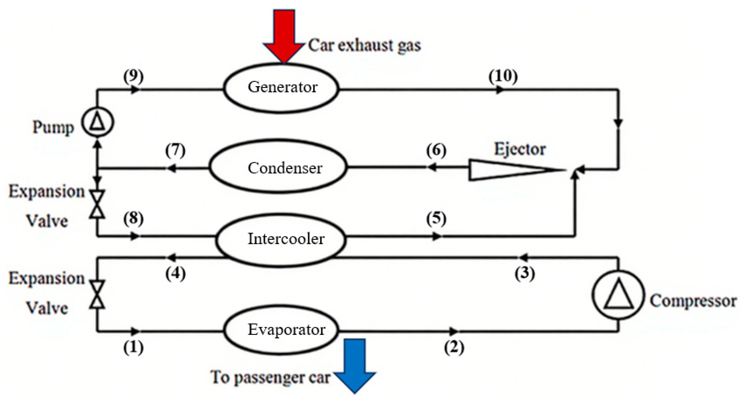
3.1. Vehicle Ejector Refrigeration Air Conditioning and the Technical Advantages

The utilization rate of primary energy can be improved with important economic and social benefits by replacing the traditional compressed refrigeration vehicle air conditioning with ejector refrigeration technology, which utilizes vehicle waste heat energy. The ejector refrigeration system compared with the vehicle compression refrigeration system has the advantages of no moving parts, a simplified structure, a small footprint, durability, and lower cost.
The ejector cycle is driven by vehicle exhaust waste heat to generate a refrigeration effect, as shown in Figure 3. The high-pressure working medium is heated and vaporized (9→10) in the generator using waste heat, forming high-pressure steam that enters the ejector nozzle. Within the nozzle, expansion and acceleration occur as pressure potential energy is converted into kinetic energy. A low-pressure zone formed at the nozzle outlet results in the low-pressure gaseous secondary flow from the evaporator. Momentum exchange and thorough mixing of both fluid streams occur in the mixing chamber. The mixed fluid subsequently decelerates and increases pressure in the diffuser section, recovering part of the pressure potential energy before entering the condenser (6→7). The condensed liquid working medium is divided into two paths. One path is pressurized by the pump and returns to the generator (7→9), completing the ejection cycle. The other path undergoes pressure reduction through the throttle valve and enters the evaporator (8→5) for endothermic refrigeration. By replacing the traditional throttle valve with an ejector, expansion energy is recovered while the enthalpy is significantly reduced, leading to lower compressor power consumption. Simultaneously, the evaporator functions as the condenser for the compression sub-cycle (1→2→3→4), where heat exchange reduces the condensation load of the compression cycle and enables synergistic operation of the dual-cycle synergy.
Compared to traditional throttle valves, ejectors demonstrate a higher COP, reducing air conditioning system energy consumption by 12% to 17% [40].
Figure 3. Vehicle ejector refrigeration air conditioning system [41].
Energies 18 03951 g003

3.2. Research Progress of Ejector Refrigeration Air Conditioning System

3.2.1. Different Working Medium Ejector Refrigeration for Vehicles

In ejector refrigeration air conditioning systems, Freon-based working medium such as R11, R12, and R22 are characterized by high thermal stability, efficient refrigeration performance, and a mature technical foundation, while their high ozone depletion potential (ODP) and global warming potential (GWP) are restricted by international agreements. Although ammonia and water are both environmentally friendly, each presents drawbacks—ammonia is toxic, and water’s evaporation temperature is limited, resulting in the failure to meet low temperature requirements. Working mediums including CO2, hydrocarbons, HFOs, and R32 possess zero ODP and low GWP, which are environmentally friendly and offer the potential for improved energy efficiency and adaptability to new technologies such as supercritical systems.
R134a is one of the most commonly utilized refrigerants in vehicle ejector refrigeration and air conditioning systems, where its effectiveness has been demonstrated through multiple performance improvements. When implemented in ejector systems, R134a improves refrigeration capacity and COP while simultaneously reducing system weight, refrigerant charge, and heat exchanger size across various conditions. Takeuchi et al. [42] reported enhancements in refrigeration capacity ranging from 25% to 45%, and increases in the COP between 45% and 65% for transit refrigeration systems operating at a cold storage temperature of 256 K. Additionally, they noted a 40% reduction in system weight and a 68% decrease in refrigerant charge. Oshitani et al. [43] observed a 15% COP increase in double evaporator systems operating at 319 K. In exhaust heat-driven systems exposed to temperatures at 803~1273 K, Zegenhagen and Ziegler [44] documented refrigeration capacity gains of 2.3–5.3 kW. Zhu and Elbel [45] investigated adjustable swirl nozzles under fluctuating conditions (as shown in Figure 4). Ünal et al. [46] achieved a 4% reduction in condenser size and a 55% reduction in evaporator size for bus air conditioning systems operating at 328 K condensation and 279 K evaporation temperatures. Galindo et al. [8] studied diesel intake refrigeration. Critical constraints were also highlighted, including a significant reduction in thermodynamic efficiency under off-design conditions with fixed ejector geometry. These efficiency losses are characterized by COP decreases from 0.099 to 0.151, primarily caused by the ejector transitioning from the efficient critical mode (double-choking) into the degraded subcritical mode (single-choking) [8], and the necessity for control mechanisms such as adjustable swirl nozzles to manage flow during dynamic operation [44]. These studies confirm the significant potential of R134a-based systems for COP enhancement, capacity reduction, and lightweight design optimization. However, operational flexibility under dynamic conditions presents challenges, particularly due to the fundamental limitations associated with momentum transfer inefficiencies and shock-induced losses associated with two-phase flow in ejectors [47].
Alternative working mediums, including water and refrigerant mixtures, have been investigated for specific vehicle ejector refrigeration applications to utilize their distinct advantages. Jaruwongwittaya et al. [48] studied a two-stage ejector cycle using water (condensation and evaporation temperatures of 328 K and 279 K, respectively), where optimized ER yielded a COP of 0.29~0.89. This configuration demonstrated superior adaptability to high condensation temperature relative to single-stage systems, with potential engine load reductions exceeding 30%. Keeratiyadathanapat et al. [41] proposed a hybrid compressed–ejector system using R134a for compression and R141b for ejection, partially powered by waste heat. This approach increased system COP by 10~20% and decreased energy consumption by approximately 20% compared to traditional compression cycles. Through CFD corrections, the mathematical model’s prediction error was reduced from 15.5% to 5.5%.
Low GWP refrigerants such as R1234yf have been investigated as environmentally friendly alternatives in ejector systems. Lawrence and Elbel [49] showed that R1234yf offers a 1–3% higher theoretical COP gain than R134a due to its higher isentropic expansion potential. Experimental results from their R134a-based ejector system demonstrated up to 10% higher COP than a conventional throttling cycle, with the enhanced performance attributed to marginally more favorable cycle configurations and operating conditions for ejector operation. While directly replacing R134a with R1234yf can decrease system capacity and COP, Sukri et al. [50] noted that adding an ejector significantly offsets these limitations by decreasing compressor power requirements and increasing COP by as much as 15%. The ER of R1234yf is significantly enhanced through geometric optimization of ejector components, specifically through adjustments to the nozzle exit diameter, mixing chamber diameter, and NXP. Galindo et al. [51] achieved an ER of 0.139 by optimizing the nozzle exit diameter (3 mm), mixing chamber diameter (3.6 mm), and NXP (5.5 mm) under adverse operating pressures specific to internal combustion engine waste heat recovery. In contrast, Suresh et al. [40] found that increasing the ejector AR to 5.33 (by reducing the throat diameter from 3.2 mm to 2.6 mm) boosts the ER of R1234yf and R1243zf by 82% under critical operating conditions, emphasizing the strong dependence of ejector performance to geometric scaling.
To broaden the technology approach, absorption and mixed working mediums have also been explored for vehicle waste heat-driven refrigeration fields. Venkataraman et al. [52] reviewed the application of fuel cell exhaust-driven absorption refrigeration systems in transit applications. They stated that a solid oxide fuel cell (SOFC) as the auxiliary power unit can provide stable waste heat to drive the absorption refrigeration cycle, thereby avoiding the performance reduction typically associated with coupling to variable engine exhaust. The temperature of the SOFC exhaust gas heat source is suitable for driving the refrigeration system. Among available working fluid pairs, ammonia–water (NH3–H2O) is appropriate for refrigerated transport at 254 K, while lithium bromide–water is more suitable for automotive air conditioning applications. Currently, there are no mature vehicle absorption refrigeration systems that have been commercialized. It is worth noting that the mixed working medium exhibits advantages in complex cycles. Pan et al. [53] proposed a coupled system integrating a supercritical CO2 Brayton cycle with ejector expansion refrigeration for engine waste heat recovery, utilizing a mixed working medium including R32 and CO2. They adopted a numerical simulation approach to investigate the refrigeration performance and key parameter influences of these refrigerants. The results show that when the mass ratio of R32 to CO2 is 0.9/0.1, the refrigeration capacity of the system reaches a value of 225.5 kW, and the integrated COP is measured at 2.05. The ejector ER is observed to increase to 1.39. When the turbine inlet pressure is 25 MPa and the temperature is 594 K, the waste heat recovery efficiency is optimal under these conditions. These findings demonstrate that tailored working medium combinations can enhance system adaptability and performance, providing flexible solutions for various heat source conditions and temperature ranges in rail and automotive applications. As summarized in Table 1, comparative studies of key performance indicators highlight the limitations of current ejector-based refrigeration systems under varying refrigerants.
The reviewed studies demonstrate significant potential for R134a-based ejector systems to improve refrigeration capacity (25~45%), COP (45~65%), and lightweight design (40% weight reduction) [42], but off-design performance remains a critical constraint, with COP dropping sharply under fixed geometries [8]. Adjustable nozzles [45] and multiple working medium systems (e.g., R134a/R141b) [41] mitigate dynamic inefficiencies, yet operational flexibility requires further optimization. Low GWP alternatives including R1234yf show promise (1~3% COP gain [49]), but geometric tuning (e.g., AR optimization [40]) is essential to compensate for capacity losses. Absorption systems (e.g., NH3–H2O [52]) and mixed-media cycles (e.g., R32/CO2 [53]) offer solutions for waste heat recovery but face commercialization barriers.

3.2.2. Transcritical System of Vehicle Ejector

A transcritical system refers to a system in which the refrigerant undergoes a supercritical state in the cycle. Its operating pressure exceeds the critical point. Unlike conventional subcritical systems that release heat through condensation, transcritical systems discharge heat through gas cooling, making them particularly suitable for high-temperature refrigeration applications. At present, CO2 serves as the mainstream working medium in the transcritical system. Other new working mediums, such as HFOs, are mostly adopted in subcritical systems due to critical temperature constraints or safety limitations. However, technology development may enable further applying of low-GWP working medium within the transcritical field.
In 2019, Ipakchi et al. [56] proposed a CO2-based transcritical cycle architecture integrating ejectors, turbines, and compressors for waste heat recovery in combined refrigeration and power supply systems. Using numerical simulation, they studied the thermal economy and the mechanistic impact of discharge pressure on system performance. The results show that a 10 bar increase in ejector discharge pressure raises energy efficiency by 16.4% while decreasing exergy efficiency by 9.2%. After optimization, the energy efficiency of the system reaches 27.42%, with an exergy efficiency of 24.21%. The corresponding net output power is 7.55 kW, the net present value is 0.3419 M$, and the payback period is 4.5 years. These results verify the economic feasibility of CO2 as a working medium in vehicle waste heat recovery applications. In 2020, Chen et al. [54] conducted experiments evaluating the thermodynamic performance of a transcritical CO2 dual-rotor intercooling refrigeration system under high-temperature environments. The results show that under the condition of 319 K, the refrigeration capacity increases by 19.8% and the COP by 12.8% compared with the basic cycle, while a significant reduction in compressor exhaust temperature occurs. This confirms that the CO2 working medium breaks through the traditional performance limit through the intermediate refrigeration technology under the high-temperature condition of mobile vehicle air conditioning. In 2022, Song et al. [55] proposed a comprehensive analytical framework for transcritical CO2 refrigeration and heat pump technology, demonstrating its efficacy in new energy vehicle air conditioning, building heating, hot water supply, and ice and snow venues. They quantify an annual energy-saving potential at 22.16% and show that introducing expansion work recovery technologies (e.g., ejectors and expanders) can improve energy efficiency by 16% to 35%. In 2023, Wu et al. [57] developed a CO2 transcritical power cycle coupled with ejector refrigeration for cascade utilization of engine exhaust gas and cylinder liner water waste heat. Using numerical simulation and multi-objective optimization, they studied the thermo-economic performance of this integrated system. The result shows that the ejector refrigeration subsystem driven by cylinder liner water reduces the CO2 condensation temperature to 301.67 K, achieving a 13.01% increase in net power and a 6.91% reduction in electricity cost. The exergy loss rate decreases from 24.94% to 17.62% (ambient temperature 284~304 K), and a 100% water utilization rate of the cylinder liner is reached alongside stable transcritical operation.
Transcritical CO2 systems demonstrate strong potential in high-temperature refrigeration and waste heat recovery, offering energy efficiency improvements (16–35%) [55] and significant COP gains (12.8%) [54] through advanced architectures like dual-rotor intercooling and ejector integration. However, trade-offs exist: increasing ejector discharge pressure boosts energy efficiency (16.4%) but reduces exergy efficiency (9.2%) [56], highlighting the need for balanced optimization. While CO2 excels in low-GWP applications and offers stability in transcritical mode [57], its economic feasibility (a 4.5-year payback [56]) and performance under dynamic conditions require further validation. Emerging low-GWP refrigerants (e.g., HFOs) remain limited to subcritical systems.

3.2.3. Structure and Parameter Optimization of Vehicle Ejector

Structural and parameter optimization of ejectors involves the precise design and adjustment of their key geometric components. These key dimensions include the nozzle throat diameter, nozzle outlet position, mixing chamber diameter and length, diffusion angle, and so on. The optimal parameter combination is typically determined by a combination of theoretical analysis, numerical simulation, and experimental verification to ensure efficient fluid mixing, supercharging, and energy transfer, thereby improving the overall performance, operational stability, and adaptability to specific operating conditions of ejectors. Structural and parameter optimization of ejectors aims to improve core performance indicators in vehicle ejector refrigeration systems. These indicators include the ER, critical pressure, COP, and operating stability in the vehicle ejector refrigeration system. Moreover, vibration noise is reduced and system reliability is enhanced under space-constrained operating conditions. System reliability and response speed are also increased during frequent start and stop conditions. Therefore, the optimization of ejector structure and parameters realizes a substantial improvement in the overall performance of the vehicle ejector refrigeration system.
Innovative design and structural optimization of vehicle ejectors play a critical role in enhancing the system energy recovery and operating condition adaptability. Takeuchi et al. [42] proposed a novel two-phase ejector system for transport refrigeration applications to address expansion energy loss in refrigeration cycles. Using experimental and numerical simulation approaches, they investigated the energy recovery mechanisms. Their results demonstrated that the adoption of a two-stage expansion nozzle significantly reduced vortex-induced energy losses in the mixing section, leading to a 25~45% increase in cooling capacity and a 45~65% improvement in the system’s COP under identical component conditions. Similarly, to minimize the evaporation temperature difference loss, Oshitani et al. [43] proposed an ejector-based system for dual evaporator refrigeration in vehicle air conditioning to address COP loss caused by evaporation temperature differences. They adopted an experimental approach combined with numerical simulation to elucidate the functional mechanisms of this system under operational constraints. The results show that a dual-stage variable ejector structure improves cabin air conditioning performance by 15% and reduces refrigeration cooling time by 20%. After optimization of the hybrid segment diameter and length parameters, the air conditioning performance of the system is enhanced by 15% at 319 K. In terms of adaptability, Zhu and Elbel [45] developed an adjustable dual-inlet swirl nozzle mechanism for throttling control in vehicle air conditioning ejectors, addressing sensitivity to fluctuating operating conditions. They adopted an experimental approach to study the flow regulation characteristics and operational stability of this control system under transient conditions. The results show that the mass flow rate of the R134a refrigerant can be reduced by 36% by adjusting the swirling strength with fixed nozzle geometry. The pressure at the nozzle inlet increases by 244 kPa for every 0.24 increase in the swirl strength when the inlet pressure is in the range of 826~1034 kPa. The control effect of this mechanism is remarkable when the pressure at the nozzle outlet is less than 500 kPa. A computational framework integrating CFD ejector characterization and one-dimensional thermodynamic modeling was developed by Galindo et al. [8] for multi-objective optimization of geometric parameters and operating conditions in internal combustion engine intake refrigeration cycles. They studied the system COP and cooling capacity enhancement of this integrated ejector refrigeration system using a numerical simulation approach combined with GAs. The results show that the intake air temperature can be reduced to 274 K and the refrigeration capacity can reach 3.66 kW, improving the energy recovery rate and adaptability to multiple operating conditions after the structure optimization under the designed working conditions. COP and refrigeration capacity can be improved more effectively through multi-objective optimization.
Regarding the optimization of vehicle ejectors’ specific structures, Lawrence and Elbel [49] proposed a double evaporator ejection cycle framework for vehicle air conditioning systems to address low-pressure refrigerant expansion loss. They studied the flow loss and frictional loss optimization under operational constraints using an experimental approach combined with numerical simulation. The results indicate that appropriate matching between the ejector throat diameter and the mixing segment diameter can improve the ejection performance. The 5 mm mixing segment reduces the flow loss by more than 40% compared to the 3 mm mixing segment. Frictional losses are significantly decreased by reducing the nozzle expansion angle from 4.0° to 2.3°. The optimization results in a peak ejection efficiency of 0.15. When the condensation temperature is 319 K and the evaporation temperature is 283.9~286 K, the COP of the system is increased by 10% at most. Galindo et al. [51] developed a parametric optimization methodology for ejectors in internal combustion engine waste heat recovery systems using the R1234yf refrigerant. They studied structural parameter effects on system ER and efficiency using numerical simulation. By adjusting the nozzle outlet diameter ( D e 3 ), the mixing chamber diameter ( D e 4 ), and the nozzle outlet position ( L e 2 ), the optimal combination was determined to be D e 3 = 3 .0 mm, D e 4 = 3.6 mm, L e 2 = 5.5 mm under the condition of the throat diameter fixed at 1.8 mm. The ER reaches the maximum value of 0.139. The results show that the deviation of 0.1 mm in the diameter of the mixing chamber leads to a 13.3% decrease in the ER. The ER decreased by 13.2% when the nozzle outlet diameter deviated from the optimal value. The compact design meets the space constraints. The critical or subcritical mode mathematical model can effectively predict the ER of variable operating conditions. Suresh et al. [40] proposed a parametric optimization framework for ejector geometric parameters (AR and NXP) in waste heat-driven air conditioning systems using low-GWP refrigerants. They analyzed the ER and ejection efficiency characteristics under varied thermodynamic conditions using numerical simulation methods. The results show that increasing the AR can significantly improve the ER. The ER of R1234yf and R1243zf reaches 0.51 at an AR of 5.33, which is 82% higher than the initial AR. The ER of R134a and R440a increase about 2.3 times under the same conditions. NXP has a significant effect on ER. The optimal NXP is 10 mm, where the ER of R1234yf is the highest. The structure optimization shows that 10 mm NXP maximizes the ejection efficiency by forming a stable supersonic secondary flow throat. The design is suitable for compact waste heat recovery systems.
The structural optimization of vehicle ejectors demonstrates substantial performance improvements, with two-stage nozzle designs enhancing cooling capacity by 25–45% and COP by 45–65% [42], while dual evaporator systems achieve 15% COP gains [43]. However, geometric sensitivity remains a challenge—minor deviations (0.1 mm in mixing chamber diameter) can reduce ER by 13.3% [51], highlighting manufacturing precision requirements. (AR) increases boost ER (82% for R1234yf at AR = 5.33 [40]); optimal NXP (e.g., 10 mm [40]) must balance efficiency with compactness. Although ejector innovations (e.g., swirl control [45], throat diameter matching [49]) mitigate losses, real-world applicability under transient conditions requires further validation.
In summary, the engine waste heat provides a feasible driving heat source for the vehicle ejector refrigeration air conditioning system. The system features no moving parts, a compact structure, and utilizes waste heat instead of mechanical compression. This scheme can reduce the energy consumption of air conditioning by 12~17% [40] and demonstrates nice performance in low-GWP working medium applications. However, the existing research still faces key challenges. Firstly, the fixed geometry ejector makes it easy to enter the subcritical mode under variable engine conditions. Secondly, real-time control strategies for adapting to heat source fluctuations during vehicle operation remain underdeveloped. Thirdly, experimental and operational data on low-GWP refrigerants in transcritical ejector systems remain limited. Future research requires attention in the following directions: developing an adaptive ejector structure responsive to operating conditions. The thermodynamic behavior of a low-GWP working medium in the transcritical cycle should be explored. This will improve the practicality and environmental benefits of vehicle waste heat recovery.

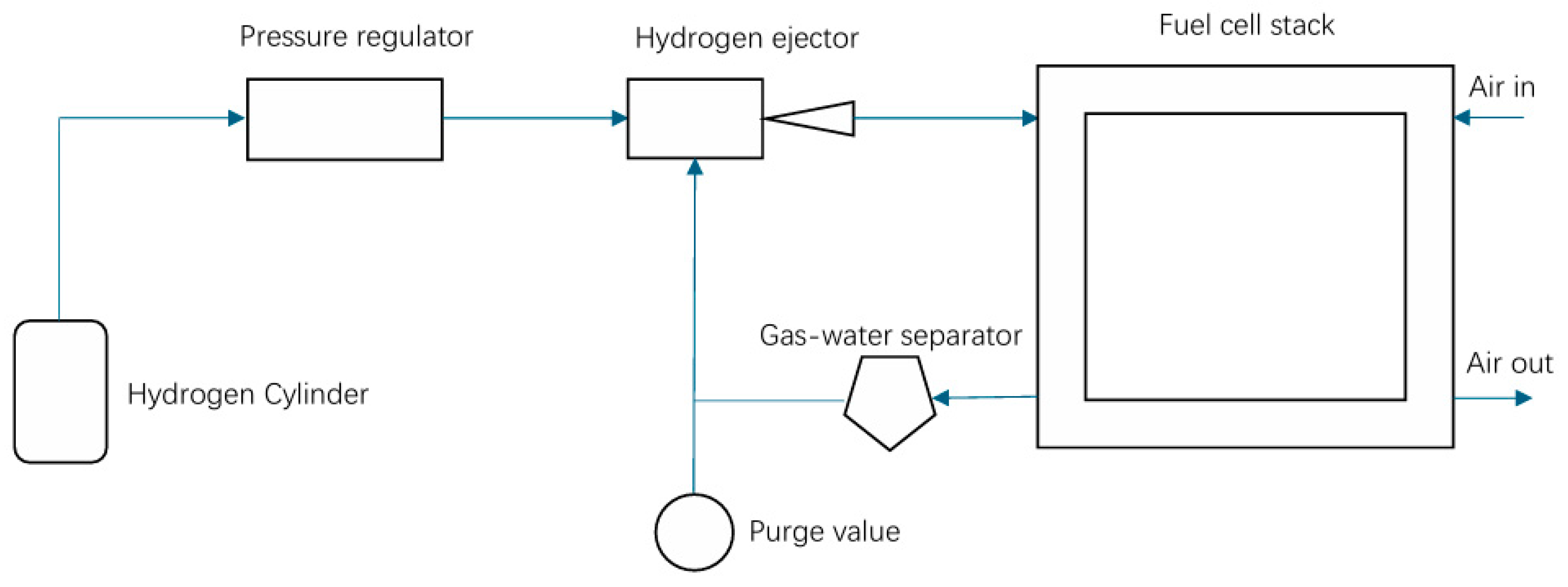
4. Application of Ejector in Hydrogen Supply System for Fuel Cell Engine

The hydrogen supply system of a fuel cell engine is significant for the hydrogen power device, which is typically composed of a hydrogen storage device, a pressure-reducing valve, a hydrogen ejector, a circulating pump, and a safety control unit. High-pressure hydrogen is stored in a dedicated tank and is subjected to multi-stage pressure reduction to enable precise control of hydrogen flow and pressure. As illustrated in Figure 5, the system ensures coordinated hydrogen supply and tail gas recirculation according to the dynamic demand of the fuel cell stack. The system is widely adopted in the fields of new energy vehicles, rail transit, ship power, distributed generation, and industrial reserve power. Key advantages include zero emissions, high energy conversion efficiency, and enhanced environmental compatibility. Furthermore, ejector-based hydrogen recirculation systems are particularly well-suited for long-endurance operations, low-temperature environments, and high-load conditions, making them ideal for clean energy applications in demanding operational scenarios.
The hydrogen ejector is the core component in a fuel cell engine’s hydrogen supply system, which can deliver hydrogen with stable flow and pressure. Hydrogen ejectors demonstrate fast response, high control precision, and high utilization rate of hydrogen. They can quickly respond to the pressure and flow demand of the fuel cell system. This technology not only improves engine performance but also significantly reduces emissions. Therefore, hydrogen ejectors are important for realizing zero-emission vehicles [59]. The hydrogen ejector has been adopted as a component in the recycling system of fuel cell vehicles, including the Hyundai Nexo fuel cell vehicle (FCV) and Honda Clarity FCV [60]. In addition, a new concept is proposed: the ejector is integrated into the hydrogen refueling process of the rail transit hydrogen refueling station. The integrated scheme can improve the effective utilization of high-pressure hydrogen [61]. The application of hydrogen ejectors represents a transformation in the vehicle industry towards cleaner and more efficient transit solutions.

4.1. Progress on Hydrogen Supply Systems for Fuel Cell Engines

4.1.1. Progress on Early-Stage Hydrogen Supply Systems for Fuel Cell Engines

The significant potential of ejector technology in improving hydrogen fuel mixing and pressure control was demonstrated in earlier related studies. In 2004, Marsano et al. [62] employed numerical simulation to design a hybrid ejector with both a constant cross-section and constant pressure for the anode recirculation system of solid oxide fuel cells. The results show that for the constant pressure ejector at an operating pressure of 380 kPa, the suction flow mass flow rate at the ejector inlet increases by 23% compared to the constant section ejector. The Mach number of the mixing chamber is reduced to 0.4. The system reforming efficiency increases by 15% relative to the baseline design. The pressure recovery coefficient of the diffusion section is 0.92. Carbon deposition is successfully inhibited in the range of 60~100% load. This early study reveals the critical role of ejectors in fuel reforming systems and lays a theoretical foundation for subsequent on-board applications. A dual ejection hydrogen fuel engine system was proposed by Kim et al. [63] in 2005 to address high-load tempering, direct ejection mixing non-uniformity, and high-pressure hydrogen supply sealing challenges. The experimental results show that the thermal efficiency of the pure direct ejection scheme is reduced by 22% due to short mixing time, hydrogen leakage, and ejection loss. The dual ejection system enables a smooth transition in the range of 59~74% load. A thermal efficiency improvement of up to 22% over the pure direct ejection scheme is demonstrated in the low-load area. However, the system still faces efficiency degradation in the high-load direct ejection area due to inadequate mixing. In 2006, Karnik et al. [64] proposed an ejector-based dual-pressure control strategy for anode hydrogen recirculation in PEMFC. The results show that the full-order observer can be constructed only by measuring the anode pressure. The critical role of ejectors in improving fuel mixing uniformity and suppressing carbon deposition within hydrogen fuel cell recirculation systems is collectively emphasized by these foundational studies.
The potential of ejector technology for resolving cost and stability challenges in fuel cell hydrogen supply systems was demonstrated in earlier related studies. In 2007, Wee [65] proposed a critical assessment framework aimed at addressing the commercialization bottlenecks in PEMFC hydrogen supply systems. Key constraints associated with conventional hydrogen production were identified in this framework, including CO2 emissions and anode catalyst poisoning risks, as well as deficiencies in high-purity hydrogen storage and transit infrastructure. He evaluated practical solutions to advance large-scale PEMFC deployment while mitigating environmental and operational challenges. The experimental data show that the metal hydride hydrogen storage system achieves a driving range of 1.35 km/g in the light vehicle. However, this system is characterized by low volumetric energy density and poor portability. The study highlights that the stability and cost control of the hydrogen supply system represent fundamental obstacles impeding the application of PEMFC in the transit field. To achieve reduced costs for the hydrogen supply system, Ahluwalia and Wang [66] proposed the utilization of an ejector for hydrogen recirculation in 2008, which has the potential to reduce parasitic power consumption by 30% in vehicle fuel cell systems. At the same time, the system cost is reduced to 108 USD/kW. The thermal management system reduces the heat dissipation area by 40% compared to the traditional design. This achievement marks the engineering validation of the ejector technology in the vehicle fuel cell system, lowering costs while boosting efficiency. To improve hydrogen supply system stability, Zhu and Li [67] adopted the numerical simulation method to investigate the ejection characteristics of the convergent nozzle ejector in the anode recirculation line of the PEMFC under both critical and subcritical operating conditions. The results show that the ER exceeds 2.0 when the primary flow pressure exceeds 5 bar. The pressure recovery coefficient of the mixing chamber can be increased to 0.95. Additionally, the boundary layer thickness of the secondary flow velocity is reduced by 38%.
Early studies of ejectors for fuel cell hydrogen supply systems found the ER in critical mode to be insufficient, with deviations in critical pressure ratio threshold prediction and low-pressure recovery coefficient in the mixing chamber. Furthermore, the recirculation ratio proved unstable under transient conditions while secondary flow ejection efficiency remained limited. These shortcomings resulted in fluctuations in carbon deposition suppression, reduced precision in anodic humidity control, and an imbalance in steam recovery rate, highlighting the pressing need for dynamic characteristic modeling and the development of multivariable cooperative control strategies to ensure reliable, high-performance operation in hydrogen supply systems.

4.1.2. Progress on Recent Hydrogen Supply Systems for Fuel Cell Engines

With the development of a multi-stage ejector structure and cooperative control strategy, the research of hydrogen supply systems for fuel cell engines has made progress in the limited working range of the traditional single ejector, pressure fluctuation, insufficient hydrogen recirculation stability, and system efficiency attenuation under the condition of wide power output in recent years.
In 2020, Kuo et al. [68] conducted both experimental and numerical investigations to evaluate the performance of a passive venturi ejector aimed at enhancing hydrogen cycle stability in PEMFC. The results show that the system’s startup time is shortened to 1000 s, the hydrogen utilization rate is increased to 98.5%, and the net efficiency of the system is improved by 19%. Voltage stability is maintained by the ejector even at power ratings as low as 3.8%. Nitrogen penetration is reduced by 42% and steam-carrying efficiency is increased by 28%. In the same year, to solve the problem of insufficient power adaptability of the hydrogen cycle ejector in the PEMFC system, hydrogen ER improvement under low power conditions was studied by Han et al. [11] through nozzle switching. The impact of secondary flow temperature, pressure, and humidity on entrainment performance of a multi-nozzle ejector was investigated through experiments combined with numerical simulation. The hydrogen supply range is extended to 0.27~1.6 g/s through design optimization involving alterations to the mixing chamber diameter and the inclination angle of the symmetrical nozzle throat. Numerical simulation and experimental verification demonstrate that the multi-nozzle structure significantly improves the hydrogen ER under low power conditions by alternating between the central nozzle and the symmetrical nozzle. It is found that the secondary flow temperature, pressure, and humidity have a significant impact on the entrainment performance, which provides an essential parameter for the hydrogen supply optimization of a wide power PEMFC system. In 2021, Zhao et al. [69] proposed a comparative assessment framework for PEMFC hydrogen supply systems. This framework analyzes cycle configurations, equipment characteristics, and control strategies to evaluate the performance differences and operational viability between ejectors and hydrogen compressors. They identified critical advantages, limitations, and control challenges across four distinct hydrogen supply architectures, with a focused analysis on the trade-offs between ejector and compressor systems. The results indicate that compressor-based recirculation systems offer a wider adjustment range but rely on external energy input. Ejector-based systems feature a simpler structure yet require geometric optimization to expand their operational range.
To resolve the narrow working range and pressure fluctuations inherent in single ejector configurations for PEMFC hydrogen supply, Chen et al. [70] in 2022 proposed a dual ejector system that optimizes geometric parameters for distinct low-power and high-power operational intervals. This system was investigated through numerical simulation combined with experimental validation for optimal design and dynamic control. Experimental results show that the dual-easer system achieves hydrogen recycling across the full power range of 70 kW PEMFC. Optimized control reduces the anode pressure fluctuation to less than 44 kPa during switching, effectively reducing the impact on battery life. In 2023, a nested double-nozzle ejector design integrating a bypass channel was proposed by Chen et al. [71] to address the limitations of narrow working ranges associated with single nozzle ejectors in PEMFC hydrogen supply systems. This design optimizes seven geometric parameters (e.g., nozzle diameter, axial spacing) to extend the operational range. A numerical simulation approach combined with experimental methods was employed to validate the system’s hydrogen entrainment capability and anode pressure fluctuation performance enhancement under variable fuel cell power conditions. Experiments show that this design achieves full coverage of power output ranging from 9 to 100% in a 150 kW PEMFC system. The required hydrogen ER is satisfied while anode pressure fluctuation is significantly reduced compared to the conventional dual ejector system. The nested nozzle design avoids pressure mutation during mode switching by sharing the mixing cavity, thereby improving the system’s stability and efficiency.

4.2. Parameter Optimization and Structural Innovation of Hydrogen Ejector

4.2.1. Optimization of Geometrical Parameter and Structure of Hydrogen Ejectors

Optimizing the geometric parameters of hydrogen ejectors plays a crucial role in enhancing the overall efficiency and stability of fuel cell hydrogen recirculation systems. Dadvar and Afshari [72] adopted the numerical simulation method to study the design parameters of the ejector of the anode recirculation system of the PEMFC. The results show that when the ratio of the nozzle throat diameter to the mixing chamber diameter is 3.81, the ER is increased to 0.8. The critical current density is reduced to 0.45 A/cm2, and the power coverage is extended to 35~100 kW. The hydrogen circulation efficiency improves by 22.7% compared with traditional compressor-based systems. Pressure fluctuations at the anode inlet are reduced by 38%. The total efficiency of the system is 54.3% and the platinum catalyst loading is reduced to 0.3 mg/cm2. This parameter optimization study proves that geometric size matching can significantly improve the cooperation efficiency of the ejector and the stack. In studying the influence of ejector geometric parameters on the recycling ratio for the optimization problem of hydrogen recycling efficiency in an 80 kW PEMFC system, Kuo et al. [73] adopted a numerical simulation method. The results show that a nozzle throat diameter to mixing chamber diameter ratio of 2.2 leads to a stoichiometric hydrogen ratio reaching its optimal value of 1.5, which is 11% higher than the benchmark configuration. This study validates the effectiveness of specific geometric parameter matching for optimizing hydrogen cycle efficiency. Yin et al. [74] adopted a numerical simulation method to investigate the optimization strategy of a double-ring cavity ejector structure, aimed at meeting the wide operating condition for hydrogen cycling demand in a PEMFC. The results indicate that optimizing the nozzle design can effectively eliminate the vortex phenomenon at the outlet, resulting in an 18.8% increase in ER at idle speed. When the diameter of the mixing chamber is 6.5 mm, the system achieves optimal hydrogen ER, system recirculation ratio, and hydrogen concentration distribution uniformity in the current range of 31.1~559.8 A. The synergistic effect of the two nozzles improves the uniformity of hydrogen concentration distribution by 15% in the high-pressure area. Adopting a numerical simulation method, Antetomaso et al. [75] studied the geometric parameter optimization strategy based on nozzle diameter scaling for the scalability of hydrogen cycle ejectors in a PEMFC system. The results show that reducing the nozzle diameter from 1.05 mm in the 5000 W system to 0.1 mm in the 300 W system ensures the ER remains in a stable range of 1.2~2.3. The gradient of pressure drop in the mixing chamber was reduced by 42%.
As to the study of the multi-parameter coupling optimization, Ding et al. [76] investigated the influence law of mixing chamber diameter ( D m ) and nozzle expansion angle (θ) on non-equilibrium condensation strength and ejection performance of hydrogen circulation ejectors for PEMFC system through numerical simulation. The results indicate that non-equilibrium condensation reduces ejector efficiency. However, this negative effect diminishes with the increase of D m and θ. There is a sensitive change zone of condensation intensity with D m = 2.65 mm and a significant weakening threshold with θ = 11.0°. An average increase of 16.8% and a maximum increase of 22.8% in the effective working range are achieved with the optimized combination of D m = 2.40 mm and θ = 11.0°. Similarly, Arabbeiki et al. [77] adopted the numerical simulation method to investigate the influence mechanism of the five-dimensional geometric parameters of the hydrogen circulation ejector for PEMFC. These parameters include nozzle throat diameter, outlet position, and mixing chamber length, all of which significantly affect the ER and the choked flow pattern. The results indicate that the diameter of the nozzle throat and the outlet position exert considerable influence on the ejection performance. The ER is increased by 20% after optimization. Shock wave formation is suppressed to enhance the stability of the flow field. The critical flow state of Mach 1.0 is maintained under design and off-design conditions. The applicability of the ejector is broadened in the wide power range of 80–101 kW.
The reviewed studies demonstrate that geometric optimization of hydrogen ejectors significantly enhances PEMFC system performance, with ER improvements up to 20% [77] and hydrogen circulation efficiency gains of 22.7% [72]. However, several critical challenges emerge. While diameter ratios (2.2–3.81) effectively optimize stoichiometric ratios [72,73], their applicability across power ranges (300 W–100 kW) requires careful scaling [75]. Non-equilibrium condensation effects, though mitigated by parameter optimization (16.8% average improvement [76]), remain a fundamental limitation. The most promising approaches combine multi-parameter optimization [76,77] with innovative designs like double-ring cavities [74], yet real-world validation under transient conditions is lacking.

4.2.2. Innovation of Adjustable Structure of Hydrogen Ejector

The innovation of the hydrogen ejector’s adjustable structure recommends dynamic adjustment components such as variable nozzles, movable throats, or adjustable mixing chambers. The innovation enables key geometric parameters, including flow area, expansion ratio, or mixing efficiency, to be adjusted in real time according to actual operating conditions when combined with intelligent control technology. Therefore, the dynamic optimization of the internal flow characteristics and energy conversion process is achieved. This significantly enhances the ejector’s adaptability, operational efficiency, and flexibility under variable operating conditions.
In 2012, Brunner et al. [78] combined numerical simulation and experimental methods to study the design, hydrogen recirculation flow rate, and stoichiometric ratio performance of an adjustable ejector for the hydrogen recycling requirements of PEMFC. The geometric parameters of the nozzle were optimized by CFD, and the electronic control needle valve was designed to adjust the nozzle opening to realize the dynamic matching of flow. The experimental results show that within a hydrogen flow range of 0.04~0.14 mol/s, controlling the needle valve displacement maintains a secondary flow pressure increase of 12~34 kPa. This pressure rise enables a consistent ER exceeding 60% across the operating range, satisfying Ballard’s minimum stoichiometric requirement of 1.6 for hydrogen recirculation. Employing experiments and numerical simulations, Jenssen et al. [79] in 2017 developed a variable geometry ejector for cascading fuel cell stacks. The results show that adopting a 50:50 anode cascade ratio reduces the global hydrogen excess rate to 1.25 and sets the throat diameter of the ejector to 4.6 mm. At the same time, this adoption extends the minimum operating power of the system to 3.8% of the rated power and achieves 99.2% voltage stability under load. In addition, the anodic voltage drop is reduced by 28% compared with the traditional design. The ejection efficiency is increased by 19% in the 10~100 kW power range. The introduction of a variable geometry ejector breaks the power adaptability limitation of the traditional fixed structure for the system. In 2022, Zhao et al. [69] proposed a comprehensive analytical framework for PEMFC gas supply systems, highlighting ejector optimization mechanisms within hydrogen supply architectures to extend operational flexibility through variable geometry nozzle adjustments. They adopted a review methodology to evaluate the structural characteristics of adjustable ejectors, identifying technological advancements that enhance working ranges through dynamic nozzle opening control. The numerical simulation results show that the optimized nozzle AR significantly improves the ejection performance, with ER reaching 62.5%~80%. In 2025, Seth et al. [80] adopted numerical simulation to study the performance of variable geometry ejectors based on moving needle valves in meeting the wide power range hydrogen cycling requirements of PEMFC. The results show that by adjusting the nozzle radius, the system’s working range can be extended from 100 kW with fixed ejectors to a range of 17~100 kW. The application of mobile needle valve technology indicates the maturity of the technology direction for the next-generation adaptive ejector.
Variable geometry ejectors demonstrate significant advantages in PEMFC hydrogen recirculation, with ER reaching 60–80% [69,78] and system power coverage expanding by 83% [80]. However, their practical implementation faces challenges. While adjustable needle valves enable dynamic flow matching (12–34 kPa pressure increase [78]), mechanical complexity and control precision remain concerns. The 50:50 cascade configuration [79] improves voltage stability (99.2%) and reduces hydrogen excess rate (1.25), but scalability to larger systems requires validation. Although variable geometry designs extend operating ranges (17–100 kW [80]), their reliability under long-term cycling and transient conditions is unproven.

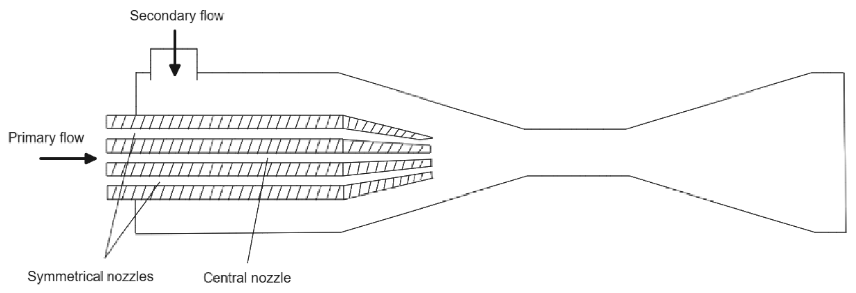
4.2.3. Multi-Nozzle Cooperative Structure of Hydrogen Ejector

The multi-nozzle cooperative structure in hydrogen ejectors involves the integration of multiple nozzles within a single ejector unit. Through the optimization of the spatial layout of nozzles, ejection angle, and flow distribution parameters, this design leverages flow field coupling mechanisms and dynamic control strategies to achieve synergistic flow behavior and enhanced mixing among nozzles. This technology aims to enhance the suction capability, improve the efficiency of energy conversion, and adapt to the needs of complex operating conditions.
The full power range coverage of the ejector is enabled by the breakthrough in the multi-nozzle structure. In 2020, Xue et al. [58] adopted the method of numerical simulation combined with experimental verification to design a multi-nozzle ejector for the PEMFC hydrogen circulation system. They investigated the effect of the simultaneous operation of multiple nozzles working together on both the circulation ratio and eddy current suppression. The results indicate that the cycle ratio of the dual-nozzle operation reaches its maximum at a main pressure of 6.5 bar. This operational mode spans the 35~100 kW power range, effectively suppresses mixing section eddy current, and maintains a stable anode inlet pressure. The total power generation is increased by 17.5 times compared with the single nozzle mode. The proposed cooperative working mode utilizing multiple nozzles marks a new phase in actively controlling the flow field within the ejector. Given the hydrogen cycling demand of PEMFC under wide operating conditions, Han et al. [11] in 2020 adopted numerical simulation methods to study the entrainment performance of multi-nozzle ejectors, which consist of a central nozzle and symmetrical double nozzles (as shown in Figure 6). The results show that the working range of the multi-nozzle ejector is extended to 0.27~1.6 g /s after optimizing the mixing chamber diameter and the symmetrical nozzle throat inclination angle. This configuration achieves a 45% increase in working range compared with the traditional single nozzle. The ER increases to more than 0.2 in the low-power section. Furthermore, the CFD simulation results show that the kinetic energy loss can be effectively suppressed by optimizing the collision position of the symmetric nozzle. In 2023, Feng et al. [9] adopted numerical simulation methods to study the design of multi-nozzle cooperative ejectors for the hydrogen recycling requirements of PEMFC under wide operating conditions. The results show that a nozzle throat diameter to mixing chamber diameter ratio of 3.2 and an ejection coefficient of 1.2 enable coverage of the power range of 35–100 kW. At this time, the anodic pressure fluctuation is less than ±0.15 bar, which is 42% lower than the single nozzle scheme. The optimized multi-stage ejection structure improves the hydrogen recycling efficiency to 68.5%, and the net efficiency of the system is 58.6%. The platinum catalyst loading is reduced to 0.25 mg/cm2, and the heat dissipation area of the thermal management system is reduced by 45% compared with the traditional design.
Regarding the dual-nozzle, in 2021, Song et al. [81] adopted experiments combined with numerical simulation methods to design a dual-nozzle ejector aimed at addressing the hydrogen cycling problem of PEMFC under wide power conditions. The results indicate that the dual-nozzle mode can cover the power range of 17~85 kW under the hydrogen supply pressure of 250~700 kPa. The ER is increased to 2.1. In comparison to the single nozzle mode, the pressure drop is reduced by 42% at low load conditions, while the mixing uniformity is increased by 37% at high load conditions. Additionally, the structure also reduces the diameter of the nozzle throat to 1.38 mm, and the pressure recovery coefficient within the diffusion section reaches 0.92. The steam-carbon ratio is stable above 2.4. Furthermore, the nitrogen permeability on the anode side is reduced by 53%. Under the low-temperature starting condition, Chen et al. [71] adopted numerical simulation combined with an experimental method to study the parameter optimization of nested dual-nozzle ejectors for the wide operating condition hydrogen cycling requirements of PEMFC. The results show that seven geometric parameters are optimized, including the diameters of the large and small nozzles and axial spacing, which the nested nozzle ejector enables a power range of 9% to 100%. The ER increases to 1.5~2.5, significantly broader than the narrow operating range achievable with conventional single nozzle ejectors. The CFD simulation shows that the pressure gradient of the mixing chamber is reduced by 19%. The nested structure reduces the pressure fluctuation at the anode inlet by 89% compared to the conventional dual ejector system. The design of nested double nozzles marks the innovation of the ejector structure into the stage of three-dimensional flow field fine control.
The development of multi-nozzle ejectors represents a significant advancement in PEMFC hydrogen recirculation systems, demonstrating remarkable performance improvements. The dual-nozzle configuration achieves a 45% wider operating range [11] and increases ER to 2.1 [81] while reducing pressure drops by 42% at low loads. However, these designs introduce new challenges: (1) The complex flow dynamics in multi-nozzle systems require precise geometric optimization, as seen in the 19% pressure gradient reduction achieved through seven-parameter optimization [71]. (2) While anode pressure fluctuations are reduced by 42–89% [9,71], the manufacturing tolerances for such systems become more stringent. (3) The benefits of increased system efficiency (up to 68.5% [9]) must be balanced against the added complexity of multi-nozzle control strategies.
In summary, the hydrogen supply system of fuel cell engines significantly improves the hydrogen cycle efficiency and operating condition adaptability through technological innovation and structural optimization of hydrogen ejectors. The cooperative design of multiple nozzles and the innovation of an adjustable structure extend the power coverage to the whole working range. The dynamic intelligent control technology reduces the anode pressure fluctuation to less than ±0.15 bar. The net efficiency of the system is improved to 58.6% [9]. The technology faces challenges, including insufficient hydrogen recycling stability across wide power output ranges, limited efficiency in suppressing transient pressure fluctuations, efficiency attenuation from reduced mixing uniformity at high loads, and performance fluctuations during low-temperature startup ejection. Future research needs to focus on the development of multi-scale dynamic optimization algorithms, the application of new erosion-resistant materials, and the construction of a cooperative regulation model for gas–liquid–solid multiphase flow. Overcoming the bottlenecks of dynamic pressure instability and multi-nozzle flow field interference is crucial to advancing hydrogen supply systems toward high efficiency and long lifespan.

5. Application of Ejector in New Pressure Reduction System for Compressed Air-Powered Vehicles

Novel compressed air-powered vehicle (APV) pressure reduction systems intelligently regulate compressed air pressure, enabling efficient and stable energy conversion between high-pressure storage tanks and power units. Core components include multi-stage reduced pressure valves, pressure sensors, and electronic control units, which dynamically optimize air pressure output and recover braking residual pressure. Ambient air is compressed to high pressure by external air compressors and stored in onboard gas storage tanks, as depicted in Figure 7. During vehicle operation, the high-pressure air is reduced to motive pressure by the pressure-reducing valve before entering the compressed air engine, where it expands to perform work that drives the vehicle. Throttling energy losses are reduced through the application of multi-stage expansion technology and power recovery-type pressure-reducing valves, thereby enhancing overall energy utilization. This system is primarily applied in zero-emission compressed APV, including urban short-distance logistics vehicles, park shuttles, and industrial special vehicles. This technology is particularly suited to low-temperature or closed environments, such as cold chain transit and mine tunnel operations, achieving both environmental protection and endurance improvement. In the new compressed air power vehicle systems, APV represents a new energy vehicle utilizing high-pressure air as the power source. These vehicles could perform truly zero pollution through compressed air-powered engines. The decompression method for high-pressure gas is regarded as a key technology in compressed APV. Due to the current high energy consumption associated with high-pressure gas decompression, a novel pneumatic vehicle decompression system has been developed, employing an air ejector to replace the throttle valve. This system increases output power by more than 13% [82].

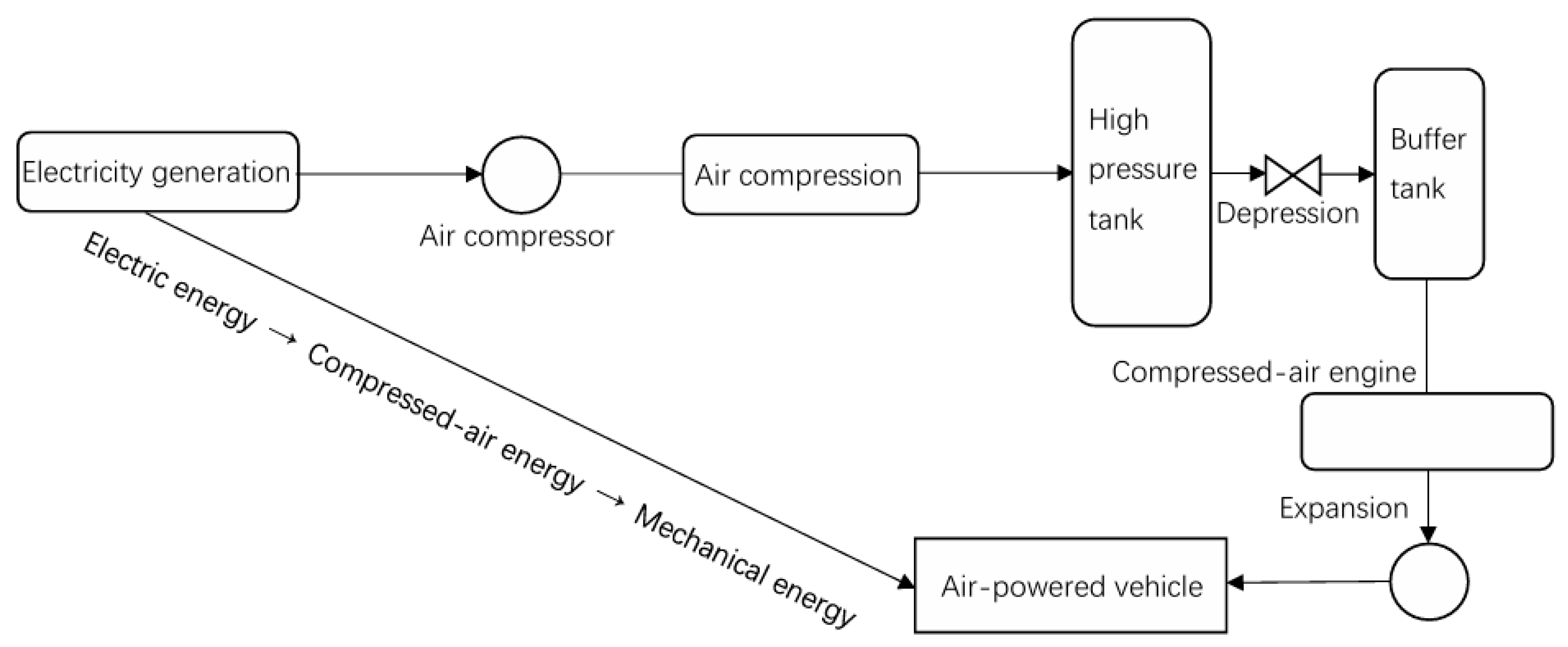
5.1. Progress in Air-Powered Vehicles and Compressed Air Energy Storage

Research on APV and compressed air energy storage has advanced from fundamental theory verification to complex system optimization. In compressed APV power systems, approximately 50% of energy loss occurs during the decompression process [83], highlighting the critical importance of optimizing pneumatic engine operation to improve overall energy efficiency. This finding reveals how traditional pressure-reducing valves constrain pneumatic system efficiency, making pressure regulation technology innovation a research hotspot. Although the technical method has gradually clarified, breakthroughs in system energy conversion efficiency remain challenging.
Many scholars investigate the technical characteristics and environmental economy of APV through reviews and numerical simulations. The results indicate that, despite advantages such as zero emissions and low maintenance costs, the technology is limited by bottlenecks, including low energy density, thermodynamic loss during expansion, and gas storage pressure attenuation. These bottlenecks lead to shorter driving ranges and lower overall energy efficiency. Meanwhile, hybrid integration, multi-level expansion optimization, and energy recovery technology are proposed as methods to enhance practicality, with the short-distance low-speed scenario regarded as the main application direction at this stage.
Verma [84] proposed a critical feasibility framework for compressed APV technologies, which integrates technical principles, development status analysis, and system viability assessments. This framework aims to evaluate structural configurations and environmental and economic advantages, as well as identify critical bottlenecks in the transition towards sustainable mobility. Verma assessed deployment barriers and scalability potential of air-powered propulsion systems in modern transport infrastructure. The results show that compressed air technology presents several benefits, including zero pollution, low maintenance costs, and convenient fuel preparation. However, low energy density is observed, and gas storage pressure significantly decreases with use. Furthermore, the expansion process causes a sharp temperature drop, leading to icing problems. The practical application process is seriously restricted by these factors. To quantify energy efficiency, environmental impact, and economic viability across the operational and manufacturing phases of compressed APV, Papson et al. [85] developed a comprehensive lifecycle assessment framework. They adopted a numerical simulation methodology to evaluate fuel economy and endurance performance under the European urban driving cycle (UDC), with parallel analysis of carbon emissions throughout the vehicle lifecycle. The results indicate that the comprehensive efficiency of the APV pump to the wheel is merely 14.7%, which is limited by the low energy density of compressed air and the thermodynamic loss of the expansion process. The UDC range is determined to be only 29 miles, with full cycle carbon emission of 626 g CO2 per mile and a fuel cost of USD 0.21 per mile. These indicators are significantly worse compared to those of gasoline and electric cars. Although this technology demonstrates zero exhaust emission characteristics, it is primarily suitable for low-speed, short-distance applications. Shi et al. [83] conducted a review to assess the technical status and formulate improvement strategies for APV, addressing low energy density, limited thermodynamic efficiency, and insufficient driving range. The influence of compressed air energy density, multi-stage expansion efficiency, and energy recovery technology on pump-to-wheel efficiency has been analyzed through theoretical modeling and comparison with existing data. Structure optimization increases APV energy conversion efficiency to 19.8%, while maintaining zero exhaust emissions. However, the vehicle range remains limited to just 29 miles, and the energy density of compressed air is significantly lower than that of lithium-ion batteries and conventional fuel systems. Therefore, the energy loss and system integration problems in the compression/expansion process need to be further studied.
Regarding hybrid APV, Marvania and Subudhi [86] proposed a comprehensive technical synthesis for compressed air engines, which integrates historical development, working mechanisms, thermodynamic efficiency modeling, and aerodynamic hybrid propulsion schemes. They evaluated critical feasibility constraints (including low energy density, rapid tank pressure decay, and irreversible expansion losses) that limit the practical implementation of pure compressed air power systems. The experimental results show that a 10 L gas storage tank supports only 2 km of endurance. However, the aerodynamic hybrid system can reduce fuel consumption by 8%~59% through braking energy recovery in cooperation with an internal combustion engine. The multi-stage expansion strategy, exhaust gas recirculation, and gas storage pressure constant technology should be optimized to improve future practicality. Therefore, it is suggested that this technology be prioritized for short-distance low-speed scenarios. To address energy efficiency and commercialization bottlenecks for compressed air hybrid power systems, Wasbari et al. [87] proposed a comprehensive optimization framework that integrates regenerative braking, multi-stage compression/expansion, and energy recovery techniques across series, parallel, and hybrid architectures. They evaluated technological feasibility approaches to address operational constraints and enable sustainable commercialization. The results showed that series, parallel, and hybrid architectures significantly improve fuel economy in the UDC. However, the commercialization of these systems is limited by the energy density of compressed air and the safety concerns of high-pressure storage tanks. Therefore, endurance improvements require lightweight materials, heat loss utilization, and system integration optimization.
The application of ejector technology to compressed air energy storage system pressure regulation is gradually improving problems, including irreversible thermodynamic loss during high-pressure gas multi-stage decompression, limited throttle efficiency of traditional pressure-reducing valves, and insufficient energy conversion rate. This decompression method of using ejectors to improve the compressed air energy storage system can be used in a new compressed APV. Guo et al. [88] designed a dual ejector system framework for adiabatic compressed air energy storage (A-CAES) through comparative optimization analysis to mitigate pressure regulation losses. They adopted an experimental approach combined with numerical simulation to validate the ejector’s operational efficacy in reducing throttling losses and enhancing energy recovery efficiency. The results show that replacing the traditional pressure-reducing valve with an ejector increased the system’s energy conversion efficiency from 61.95% to 65.36%, representing a 3.41% improvement. This outcome verifies the ejector’s effectiveness in reducing pressure losses and optimizing the energy storage system’s energy conversion efficiency. Ejector technology has been introduced into the pressure control field, providing a new method for improving pneumatic system energy efficiency. Chen et al. [89] employed a novel ejector-based throttling strategy to mitigate throttling losses in A-CAES systems. The results show that optimal values exist for the ejector ER and the active flow pressure, while the system performance is less affected by ambient temperature. By classifying pressure into three levels (high/medium/low), high-pressure air drives the ejector to compress low-pressure air to medium pressure. This strategy reduces throttling exergy destruction by 23.1% and increases the system’s round-trip efficiency by 2.00 percentage points (from 66.22% to 68.22%). Zhou et al. [90] employed numerical simulation to reduce throttling losses in compressed air energy storage systems by replacing throttle valves with ejectors. The results indicate that by recovering the outlet air pressure energy from the third-stage compressor, the ejector reduces the compressor’s unstable speed range from 0.491 to 0.771. Simultaneously, the system’s average exergy efficiency is observed to increase with increasing initial gas storage pressure, with the optimization effect being particularly significant at low initial pressure.
APV exhibits zero-emission advantages but faces critical limitations in energy density and thermodynamic efficiency, restricting its viability for mainstream mobility. While structural optimizations can improve energy conversion efficiency to 19.8% [83], the technology remains impractical for long-range applications, with a maximum UDC range of only 29 miles and high lifecycle emissions (626 g CO2/mile) [85]. Hybrid architectures mitigate some limitations—reducing fuel consumption by 8–59% [86]—but cannot overcome the fundamental energy density gap versus batteries or fuels. Ejector-based pressure regulation shows promise in CAES systems, improving efficiency by 3.41% [88] and reducing exergy losses by 23% [89], yet these gains are insufficient to offset APV’s core drawbacks. For sustainable deployment, APV systems must prioritize niche applications (e.g., low-speed, short-distance transport) while integrating hybrid solutions and advanced materials to address energy storage and expansion losses.

5.2. System Integration Optimization of Air Ejector

Compressed air potential energy historically powered certain manufacturing or transit systems as a versatile energy source. In the late 19th century, this form of energy was adapted for vehicle propulsion. During the latter half of the 20th century, considerable efforts were directed toward using compressed air for electrical energy storage [91]. Currently, advances in ejector technology are being incorporated into compressed APV.
The efficiency of air ejectors is significantly improved through thermodynamic optimization in compressed air energy storage systems, where exergy loss and heat dissipation are simultaneously reduced, enabling adaptation to high fluctuating energy demand. In 2016, Guo et al. [88] proposed a comparative dual-system framework for A-CAES to mitigate exergy loss during pressure reduction by integrating multi-level pressure regulation through ejector technology. They contrasted a traditional pressure-reducing valve operating between 6.40 and 2.50 MPa (System 1) with stepwise ejector control (System 2), developing thermodynamic optimization methods to reduce throttling loss. They adopted a combined numerical simulation and experimental methodology to quantify exergy recovery and validate thermodynamic enhancement effects in multi-stage pressure regulation processes. The results demonstrate that the ejector increases turbine inlet pressure through momentum exchange. Consequently, the power output of System 2 rose from 3.80 MW to 5.51 MW, and the overall energy conversion efficiency improved from 61.95% to 65.36%. Parameter analysis indicates that mixing a working fluid at 5.00 MPa with a suction fluid at 1.80 MPa effectively balances pressure loss and flow gain, thereby validating the proposed technique’s optimization potential for boosting energy storage density. In 2023, Rabi et al. [92] analyzed the ejector thermodynamic optimization strategy to optimize compressed air energy storage systems. The results demonstrate that the incorporation of ejectors significantly enhances gas–liquid mass transfer and energy recovery, thereby effectively addressing the problems of high heat dissipation and low efficiency in traditional compressed air energy storage systems. This thermodynamic optimization strategy enables ejector technology to effectively accommodate the intermittent and highly fluctuating energy output characteristics of compressed APV. In 2024, Liu et al. [93] adopted numerical simulation to study pressure loss during throttling processes in compressed air energy storage systems and to investigate thermodynamic optimization of ejector-enhanced systems. The results indicate that the round-trip efficiency of the new system was improved by 3.07%, while exergy loss decreased by 401.9 kW compared to the traditional adiabatic system during the decompression process. Based on advanced exergy analysis, it is recommended that system improvements should prioritize optimizing the ejector structure, followed by the optimization of the turbine and compressor.
Through intelligent design and optimal configuration, the air ejector multi-system cooperative integration was achieved. Meanwhile, the deep integration of air ejector technology with other related systems, such as power, control, and sensing, is required. Efficient cooperation and information exchange among subsystems have been realized, thereby improving the overall system performance, energy efficiency, and reliability. In 2021, Sadeghi and Ahmadi [94] proposed a combined cooling, heat, and power supply system that integrates compressed air energy storage with CO2 ejector refrigeration technology. The results indicate that the system consumes 72.02 MW of power during the charging phase while generating 136.56 MW in the discharge phase, providing a 1.96 MW cooling load and a 65.8 MW heat load. The cycle efficiency is found to be 81.15%, and the exergy efficiency is 56.57%. After optimization, the exergy efficiency increases to 68.19%. Adopting the numerical simulation method in 2022, Cao et al. [95] studied an A-CAES system aimed at optimizing the configuration of an integrated single ejector in the final compression stage. The results show that by ejecting the third-stage compressed air as the secondary flow, the compressor backpressure fluctuation range is reduced by 39.87%. When the initial gas storage pressure is 5.0 MPa and the ER is 0.168, the system achieves a round-trip efficiency higher than that of the traditional constant voltage operation modes by 2.73%. Meanwhile, reaching the highest value of 57.94%, energy consumption is reduced by 5.36%. The findings demonstrate that the ejector significantly broadens the compressor’s working range and improves energy storage efficiency. Additionally, this confirms that ejector technology contributes to improving compressor stability under variable working conditions, which is particularly important for the frequent start and stop conditions of compressed air energy storage systems. In 2023, Yang et al. [96] utilized a numerical simulation method to investigate pressure regulation in compressed air energy storage systems, specifically discussing the power generation time and total power generation of an energy storage system integrated with an ejector and burner. The results indicate that with the ejector coefficient of 0.8 and the burner heat power of 10 MW, the system power generation time is extended to 12.45 h, with total power generation reaching 140,052 kWh. Compared to the non-supplementary combustion mode, these values represent increases of 15.6 times and 17.5 times, respectively. The ejector mixes high-pressure air with low-pressure ambient air, significantly improving the air mass flow rate at the turbine inlet, while the burner provides thermal energy compensation. This integrated approach effectively overcomes the inherent limitation of short power generation duration in traditional A-CAES systems.
The integration of ejector technology in CAES demonstrates significant thermodynamic improvements yet faces critical challenges in practical implementation. While Guo et al. [88] achieved a 3.41% efficiency gain (61.95% to 65.36%) through dual-system ejector optimization, this improvement remains marginal relative to the energy demands of large-scale applications. Similarly, Liu et al. [93] reported a 3.07% round-trip efficiency increase, highlighting the limitations of incremental gains from ejector-based throttling loss mitigation. The multi-system integration approach shows promise, with Yang et al. [96] achieving a 17.5-fold power generation increase through ejector–burner hybridization, but this introduces complexity in control and thermal management. The technology’s adaptability to fluctuating energy demands is validated by Rabi et al. [92], yet system-level reliability under dynamic conditions requires further validation. While ejectors enhance compressor stability (39.87% backpressure fluctuation reduction [95]), their scalability to industrial-scale CAES remains unproven.
In summary, ejector technology has been recommended for use in the pressure reduction systems of compressed air-powered vehicles, offering significant improvements in energy conversion efficiency. The multi-stage pressure regulation and residual pressure recovery strategy effectively reduces traditional throttle valve losses, improving system output power efficiency by 13% [82]. However, technological development is limited by core bottlenecks, which include turbulence loss caused by thermodynamic irreversibility, the synergistic contradiction between lightweight gas storage and thermal management, and insufficient ejector dynamic matching capability. Future efforts should aim to achieve coordinated improvements in both energy density and efficiency, address temperature drops during the expansion process, enable dynamic matching of multi-stage decompression parameters, and enhance the system’s round-trip efficiency. These advancements are essential to overcoming key technical challenges and promoting the practical implementation of energy-efficient compressed air technologies.

6. Other Applications of Ejectors in the Field of Rail Transit

As rail transit develops towards high speed, intelligence, and sustainability, ejector technology innovation expands from single-function realization to multi-objective collaborative optimization, offering significant value for a wide range of related systems. Active airflow control dynamically adjusts bow mesh contact force within the pantograph pneumatic system with simultaneous aerodynamic noise suppression. The train vacuum toilet system enhances sewage collection efficiency and reduces water consumption through negative pressure suction. For the train ventilation system, multi-stage ejection combined with personalized air distribution strategies optimizes thermal environment adjustment precision and enhances energy efficiency. Within track cleaning and maintenance devices, stubborn pollutants are efficiently removed from infrastructure and vehicle surfaces through high-pressure ejector technology.

6.1. Pantograph Pneumatic System

As a critical component device in electric traction vehicles, the pantograph pneumatic system achieves precise control of pantograph lifting and contact pressure through coordinated operation of pneumatic actuators, solenoid valves, and sensors. This system dynamically adjusts the contact state between the pantograph slide and the catenary wire, with widespread application in high-speed railways, urban rail transit, and trolley buses. Rising operating speeds of high-speed trains make aerodynamic optimization of pantographs a key research direction to improve bow network flow quality.
Ikeda et al. [97] proposed an ejector-integrated pantograph design for high-speed trains, leveraging controlled airflow from the slide surface to modulate aerodynamic noise suppression and lift dynamics. They adopted a wind tunnel experimental methodology to investigate the impact of ejector flow characteristics on critical aerodynamic performance metrics under operational conditions. Unilateral ejection alters the lift coefficient by 0.04, translating to a 20 N lift force variation for a full-scale pantograph (1 m span) at 300 km/h, enabling active uplift force control. Bilateral ejection reduces narrowband noise at the vortex-shedding frequency (430 Hz) by 5 dB (from baseline levels), though inducing broadband noise above 1 kHz due to ejector flow. PIV confirmed that ejected jets suppress vortex roll-up and stabilize trailing edge shear layers, simultaneously enhancing aerodynamic stability and mitigating aeroacoustic noise. Building on prior research, subsequent scholars began exploring more efficient pneumatic control systems. To modulate aerodynamic stabilization in high-speed trains, Ikeda et al. [98] proposed a dual-source ejector-integrated pantograph lift control system leveraging external and self-supplied airflow. They adopted a combined numerical simulation and wind tunnel experimental approach to investigate the aerodynamic control effectiveness of these ejector configurations under operational flow regimes. The results indicate that the lift coefficient can be significantly altered by the internal circulation airflow within the self-supplied ejector, achieving a lift adjustment range of up to ±20 N at 300 km/h. Numerical simulations further reveal that the trailing edge vortex system can be reconstructed and the separation flow inhibited through ejector flow. This method effectively resolves contact force instability caused by pantograph lift fluctuation, offering a practical solution for low-noise pantograph design and current collection performance optimization.
Suzuki et al. [99] proposed a self-circulating ejector system for pantograph aerodynamic regulation in high-speed trains, utilizing internal airflow circulation to enhance lift stability and aerodynamic control. They adopted a combined numerical simulation and wind tunnel experimental approach to investigate the aerodynamic–aeroacoustic performance of this integrated system under operational conditions. The results show that trailing edge ejection can significantly alter the flow structure, forming a cyclic vortex system and increasing the lift coefficient by 0.25. During experimental validation, the circular ejector slightly reduces the lift control range while effectively suppressing lift fluctuations in the high-speed regime. The practicality of this ejector system for the collaborative optimization of pantograph aerodynamic noise and lift force is confirmed. This research improves the early ejector design through structural innovation, pushing circulating airflow control technology toward engineering applications. With growing emphasis on high-speed train energy efficiency requirements, recent research has increasingly focused on aerodynamic drag optimization as a key area of improvement. Huang et al. [100] proposed an ejector-integrated aerodynamic optimization framework for high-speed train pantographs, leveraging position-, velocity-, and slot-width-adjusted flow field modulation to achieve drag reduction. They adopted a numerical simulation with an improved delay-detached eddy simulation model to analyze ejector control technology effects on flow structure and resistance characteristics under actual aerodynamic operating conditions. The results demonstrate that when the distance between the ejector slot and the pantograph leading edge is less than 0.6 times its height and the ejector velocity is below 0.6 times the train speed, the drag reduction rate continuously increases with rising ejector velocity, reaching a maximum reduction of 25.03%. Reducing the ejector slot width enhances the drag reduction effect, though ejector energy consumption requires consideration. Increasing ejector velocity contributes more significantly to drag control than expanding slot width. Overall, train energy saving is only applicable when the ejector speed remains below 0.6 times the train speed. This research provides a theoretical basis for designing ejector drag reduction systems in high-speed trains.
The integration of ejector technology in high-speed train pantographs demonstrates significant potential for aerodynamic optimization yet presents notable trade-offs in practical implementation. While Ikeda et al. [97] achieved a 5 dB reduction in narrowband noise (430 Hz) through bilateral ejection, this came at the cost of induced broadband noise above 1 kHz, highlighting the challenge of balancing noise suppression across frequency ranges. The technology shows greater promise in aerodynamic stabilization, with Ikeda et al. [98] demonstrating ±20 N lift adjustment at 300 km/h, effectively addressing contact force instability. However, Huang et al. [100] revealed critical limitations in energy efficiency, where maximum drag reduction (25.03%) is only achievable when ejector velocity remains below 0.6 times train speed—a constraint that may limit operational flexibility. The self-circulating ejector design by Suzuki et al. [99] improved the lift coefficient by 0.25 but sacrificed some control range, underscoring the need for design compromises.

6.2. Train Vacuum Toilet System

As an efficient sanitary treatment device based on negative pressure suction technology, the train vacuum toilet system generates a pressure difference in the pipeline through a vacuum generator to enable rapid collection and sealed transmission of excreta. Compared to traditional gravity drainage systems, this approach offers significantly enhanced water-saving efficiency. Additionally, the use of narrower pipelines reduces both the overall weight and space requirements of the train. Owing to these advantages, vacuum toilet systems are widely applied in high-speed railways, subways, long-distance buses, and aviation.
Guo [10] experimentally combined a dynamic pressure response model to study the energy-saving optimization of a pneumatic ejector circuit, addressing the energy consumption problem of vacuum sanitation systems. A variable vacuum system incorporates a mass sensor to detect excreta volume and activate a control linkage that adjusts air supply, dynamic regulating vacuum degree based on waste amount. For ejectors, a pneumatic circuit pressure variation equation was established, confirming the feasibility of generating a small vacuum at low waste volumes. The experiments demonstrate that, compared to fixed vacuum systems, this design achieves over 50% energy savings within 0.2×10⁻³~1.6×10⁻³ m3 waste volumes while exceeding 99% collection rates. Research on the aerodynamic characteristics of similar vacuum sanitation systems reveals multi-dimensional propulsion characteristics. Guo et al. [101] proposed an intelligent sanitary ware system integrating liquid level/mass sensors and adjustable pneumatic ejector circuits for demand-matching vacuum discharge power, addressing energy-saving requirements in next-generation sanitation systems. A combined experimental and numerical simulation approach was adopted to develop and validate a control strategy capable of dynamically adjusting the ejector air supply duration based on real-time excreta volume. The results demonstrate that compared with traditional fixed vacuum systems during manual waste collection, the variable vacuum system saves over 30% of energy. The effectiveness of the pneumatic ejector in achieving adaptive energy adjustment within the vacuum sanitation system is verified, providing a theoretical basis for energy-saving optimization of ejector-driven vacuum systems.
To enhance aerodynamic efficiency and vacuum-generation performance in train sanitation applications, Fujino et al. [102] developed a multi-parameter diagnostic framework for optimizing vacuum ejector systems, integrating valve sizing, pipeline configurations, and gas-path layouts. They adopted a combined experimental and numerical simulation approach utilizing high-response fast-flow sensors for transient pressure/flow measurements to quantify energy efficiency dynamics under operational transient conditions. The results indicate that pressure loss can be reduced by increasing the diameter of the pressure relief valve and optimizing pipe size and path, which increases the ejector vacuum discharge rate by 18%. It is proven that pneumatic component optimization reduces system supply pressure to 0.6 MPa, achieving 26% lower compressed air consumption while maintaining ejector functionality. This provides a quantitative basis for the energy-saving design of vacuum toilets. Advancing sensor technology drives intelligent progression of vacuum regulation research. Fujino et al. [103] developed a multi-parameter impact assessment framework for aerodynamic energy consumption in train vacuum sanitation systems, quantifying the influence mechanisms of ejector operational states and sewage storage tank volumes on system efficiency. The experimental methodology implemented high-response pneumatic power meters to measure real-time pressure, flow rate, and airflow energy dissipation. By actively adjusting sewage tank volumes and controlling the start–stop sequences of the ejector, the study provided detailed insights into system energy dynamics. It is found that reducing the sewage tank volume increases the vacuum pressure to −55 kPa while shortening the ejector air supply time to 2.5 s. The results show that the optimized system maintains a sewage transmission distance of 2.24 m, reducing aerodynamic energy consumption by approximately 20% compared to the initial state. The feasibility of energy consumption optimization through ejector timing control and sewage storage tank structure improvement is verified.
The reviewed studies demonstrate significant progress in ejector-based vacuum sanitation system optimization yet reveal critical limitations in practical implementation. While Guo [10] achieved a remarkable 50% energy savings through dynamic vacuum adjustment, this performance is constrained to a narrow waste volume range (0.2 × 10⁻³~1.6 × 10⁻³ m3), potentially limiting broader applicability. Fujino et al. [102] showed that component optimization could reduce air consumption by 26%, but the achieved 18% discharge rate improvement may not justify the required system redesign costs in existing installations. The intelligent system by Guo et al. [101] presents a 30% energy saving advantage yet raises concerns about sensor reliability and maintenance complexity in harsh sanitation environments. Fujino’s subsequent work [103] demonstrated 20% energy reduction through tank volume optimization, but the achieved −55 kPa vacuum pressure may be insufficient for certain high-demand applications.

6.3. Train Ventilation System

As a key system for maintaining carriage air quality and environmental comfort, the train ventilation system is controlled through dynamic airflow organization and pressure balance. It enables air circulation and filtration, temperature and humidity control, and targeted pollutant removal. Its core framework integrates efficient filtering modules, low-noise wind units, and an intelligent control unit. The system performs effectively in high speeds or closed environments while maintaining stable cabin air pressure and fresh air supply, and is widely applied in high-speed rail, subway, intercity train, and other rail transit fields.
Starcheous et al. [104] proposed a cascaded power converter-integrated heating system for railway transit units, utilizing hybrid-controlled multi-stage ejectors wherein the first stage mixes converter-generated high-temperature air with ambient air, and the second stage dynamically regulates recirculation rates through valve modulation to achieve compartment-specific thermodynamic precision. A combined theoretical and experimental approach was employed to develop and validate this novel system for dynamic temperature regulation across operational load ranges. The experiments show that implementing an adjustable ejector increased the maximum system pressure to 0.6 MPa while thermal efficiency improved by 40% over conventional electric heating systems. Through the secondary recovery of waste gas heat, the energy utilization rate reaches 78%. Research confirms that the ejector structure effectively solves the contradiction between high-temperature air transit and comfort control. The scheme provides an innovative solution for energy-saving heating of transit equipment. Although energy efficiency is significantly improved, the scheme’s fine regulation of airflow distribution within the carriage remains to be further explored. By analyzing airflow uniformity and thermal comfort through detailed CFD modeling of passenger thermal loads and diffuser geometries to optimize airflow distribution efficacy, Iranzo et al. [105] proposed a comparative ventilation framework for railcar environmental control systems. They adopted a numerical simulation to evaluate vertical ejector versus horizontal guide diffuser airflow regulation during actual ventilation operational. Research shows that the original diffuser’s vertical ejector caused the local wind speed in the passenger area to reach 3.7 m/s—exceeding the comfort standard limit of 1 m/s—while the improved design reduces the maximum wind speed to 2.4 m/s through horizontal diversion and better balances the temperature field and velocity field. The results provide an important basis for optimizing railway vehicle ventilation systems. Schmeling et al. [106] developed a multi-nozzle personalized ventilation system aimed at optimizing thermal comfort in high-temperature rail transit environments. The system features six adjustable airflow nozzles designed to modulate localized thermal sensations based on passenger feedback and equivalent temperature metrics. They adopted an experimental methodology combining equivalent temperature measurements and subjective evaluations from 40 subjects to analyze flow rate-dependent thermal environment dynamics across 294~314 K operational ranges. The results show that the maximum flow rate of the ejector could reduce the chest equivalent temperature by up to 9 K, significantly improving thermal comfort. Although the nozzle orientation remains fixed, individualized control of airflow rates led to a 20% increase in subjective comfort ratings. However, the study also identified a residual risk of thermal discomfort in the head and foot regions due to insufficient airflow distribution. This research marks a paradigm shift from global energy saving to precise and comfortable regulation of railway ventilation systems. Dynamic perception technology should be further combined in the future to achieve full-area thermal environment optimization.
The reviewed studies highlight significant advancements in ejector-based thermal regulation for rail transit but reveal critical limitations in practical implementation. While Starcheous et al. [104] achieved a 40% thermal efficiency improvement and 78% energy utilization rate, the system’s reliance on 0.6 MPa pressure raises operational safety and maintenance cost concerns. Iranzo et al. [105] demonstrated that optimized diffuser designs reduced local wind speeds from 3.7 m/s to 2.4 m/s, yet this still exceeds the 1 m/s comfort standard, indicating persistent challenges in balancing ventilation efficacy with passenger comfort. Schmeling et al. [106] showed promising results with a 9 K reduction in equivalent temperature and 20% improvement in subjective comfort ratings, but the system’s inability to address thermal discomfort in the head and foot regions reveals fundamental limitations in localized airflow distribution.

6.4. Rail Transit Cleaning and Maintenance Device

Rail transit cleaning and maintenance equipment is specialized for removing pollutants from rail infrastructure and vehicle surfaces, integrating high-pressure ejector cleaning technology, intelligent identification and positioning technology, and environmental protection recovery treatment technology. This equipment efficiently removes dust from track slabs and contact nets, along with stubborn stains on car bodies. Featuring modular designs with multi-modal adaptability, such systems are deployed in various forms, including track grinding vehicles, tunnel-cleaning robots, and platform maintenance units. It is widely used across high-speed railway lines, urban subways, freight railways, and cross-sea bridge track scenarios. Vasic et al. [107] adopted combined experimental and numerical simulations to investigate cleaning technologies for a low-adhesion railway track. These technologies include high-pressure water ejectors, sand ejectors, and Sandite, a mixture of quartz sand and gel. A high-pressure water ejection system employing 1000 bar pressure and a 30-degree nozzle angle effectively removes the contaminated film from the track blade. However, the residual wet film requires treatment with Sandite to increase the adhesion coefficient to 0.09. The results indicate that the cleaning efficiency of the ejector peaks at 40 mph, although leaf contamination is prone to reappearing. Sodium bicarbonate spray applied at 4.5 mph selectively strips pollutants and exhibits environmental protection characteristics. Although such combined mechanical–chemical cleaning schemes have achieved initial results, their high-speed cleaning efficiency and long-term stability still require further optimization.
In summary, the innovative application of ejectors in rail transit has significantly enhanced overall system performance across multiple subsystems. The pantograph pneumatic system utilizes self-supply gas ejection technology enabling ±20 N dynamic lift adjustments at 300 km/h [98]. A vacuum toilet system incorporating intelligent sensing and variable vacuum ejectors achieves over 50% energy savings [10]. The ventilation system, combined with multi-stage ejection and personalized nozzle design, has demonstrated a 40% improvement in thermal efficiency [104]. Track cleaning devices employing 1000 bar high-pressure ejector technology efficiently remove pollutants. However, challenges remain in balancing high-frequency noise generation with ejector energy consumption. Problems of low-load vacuum stability and scaling attenuation coexist, while carriage airflow uniformity and dynamic thermal response precision require optimization. High-speed cleaning, durability, and antifouling capabilities are limited. Future research requires overcoming bottlenecks in high-frequency noise suppression, low-load vacuum stability improvement, carriage airflow uniformity optimization, and high-speed cleaning durability enhancement to realize collaborative performance and sustainability upgrades for ejectors in rail transit systems.

7. Conclusions

This paper comprehensively reviewed the application and research progress of ejector technology in rail transit driven by energy conservation and energy transition. This review summarizes current technical achievements, identifies research shortcomings, and indicates future research hotspots.
Based on the comprehensive review, the following conclusions can be drawn:
(1)
Vehicle ejector refrigeration air conditioning is driven by vehicle waste heat energy and utilizes ejector refrigeration technology to replace the traditional compressed refrigeration system in automobiles. This system can reduce the energy consumption of the air conditioning system by 12~17%. Its application has important economic and social benefits for improving the primary energy utilization rate.
(2)
The hydrogen ejector serves as the core component of the fuel cell engine’s hydrogen supply. It not only improves engine performance but also significantly reduces emissions, resulting in a 9% reduction in high-pressure hydrogen demand. It represents one of the key technologies for realizing zero-emission vehicles.
(3)
In pneumatic vehicle pressure reduction systems, throttle valves are replaced by air ejectors, a design modification that increases system output power by more than 13%.
(4)
In pantograph pneumatic systems, the lift force is dynamically adjusted by ±20N at 300km/h through self-supply gas ejection technology. Vacuum toilet systems exceed 50% by intelligent sensing and variable vacuum ejectors. Ventilation systems improve thermal efficiency by 40% through the combination of multi-stage ejection and personalized nozzle design. Track cleaning devices efficiently remove pollutants by adopting 1000 bar high-pressure ejector technology.
However, there are still many challenges affecting the current research:
(1)
In rail transit engine waste heat recovery, the fixed geometry ejector readily enters subcritical mode under variable engine operating conditions, causing the cooling capacity to be suddenly reduced and the coefficient of performance to be significantly attenuated. Data scarcity exists for global warming potential working fluids applied in the transcritical cycles. The coefficient of performance of traditional compression refrigeration systems is much lower than the theoretical value for ejector refrigeration, limiting the system’s actual energy efficiency improvement.
(2)
In hydrogen ejector technology, insufficient stability of hydrogen recycling under wide power output causes anodic pressure fluctuations exceeding ±0.15 bar during transient conditions. Mixing uniformity decreases at high load, resulting in the system’s net efficiency decaying to 58.6%. The ejection ratio fluctuates more than 7.3% when starting at low temperatures, while hydrogen recovery efficiency reaches only 97.2%.
(3)
In pressure reduction systems for new compressed air-powered vehicles, turbulence loss is caused by thermodynamic irreversibility, with conventional pressure relief valves inducing 50% energy loss. Although the ejector increases power output by 13%, the system round-trip efficiency is only 57.94%. Synergistic contradictions exist between lightweight gas storage and thermal management.
(4)
In other rail transit applications, a prominent contradiction exists between ejector noise reduction and energy consumption balance in the pantograph pneumatic system. Although the bilateral ejector reduces narrowband noise by 5 dB, wideband noise above 1 kHz is triggered. Insufficient vacuum stability occurs in the vacuum toilet system under low load conditions, while scaling-induced performance reduction is observed. The ventilation system’s airflow distribution uniformity requires optimization. The insufficient high-speed cleaning durability of the high-pressure ejector cleaning device easily allows pollutant reproduction.

8. Future Perspectives

Future research will focus on the following topics, as summarized in Table 2:
(1)
Through dynamic intelligent regulation and structural innovation, a machine learning-based ejector pressure threshold prediction algorithm should be developed to improve variable working condition adaptability. A nested double-nozzle ejector requires a different design to extend power coverage. An adjustable swirl nozzle and mobile needle valve structure should be developed to achieve dynamic flow matching. Multi-nozzle flow field interference suppression technology should be further developed.
(2)
Through multi-system energy efficiency collaborative optimization, a hybrid pneumatic–electric architecture integrating residual pressure recovery and a multi-level decompression strategy should be established. Integration between fuel cell hydrogen supply systems and refueling station ejectors requires enhancement to improve hydrogen recycling efficiency. The cylinder liner water-driven ejector cooling system is to be strengthened to reduce the exhaust exergy loss rate.
(3)
Through the application of transcritical cycles and environmentally friendly working medium, research on CO2 transcritical ejector refrigeration systems can be deepened through backpressure optimization to improve round-trip efficiency. The injectivity characteristics of global warming potential working fluids require investigation under wide operating conditions to enhance the coefficient of performance. Ammonia working medium applications are to be expanded in low-temperature refrigerated transit to overcome the environmental limitations of conventional refrigerants.
(4)
Through the construction of a multi-physics field simulation platform integrating computational fluid dynamics and electrochemical mechanisms (e.g., fuel cell multiphase flow coupling), an ejector-stack cooperative model should be established to overcome hydrogen recirculation instability across wide power ranges.
Through the above technological breakthroughs, the cross-generation upgrade of ejectors to high energy efficiency, long life, and intelligence will be promoted, and the green and low carbon transformation of rail transit will be facilitated.

Author Contributions

Conceptualization, Y.L. and H.H.; methodology, Y.L.; software, Y.L.; validation, Y.L., H.H., Y.G., Y.Y. and S.L.; formal analysis, Y.L.; investigation, Y.L.; resources, S.S.; data curation, Y.L.; writing—original draft preparation, Y.L.; writing—review and editing, H.H.; visualization, H.H.; supervision, Y.G.; project administration, S.L.; funding acquisition, Y.L. All authors have read and agreed to the published version of the manuscript.

Funding

This research was funded by the Fundamental Research Funds for the Provincial Universities of Liaoning, grant number LJ212410150010.

Conflicts of Interest

The authors declare no conflict of interest.

Nomenclature

EREntrainment ratio
PEMFCProton exchange membrane fuel cell
COPCoefficient of performance
MLartificial intelligence
AIMachine learning
ANNsArtificial neural networks
GasGenetic algorithms
ARArea ratio
NXPNozzle exit position
CFDComputational fluid dynamics
PIVParticle image velocimetry
ODPOzone depletion potential
GWPGlobal warming potential
FCVFuel cell vehicle
APVAir-powered vehicle
A-CAESAdiabatic compressed air energy storage
SOFCSolid oxide fuel cell
m s . Ratio of entrained fluid flow rate
m p . Motive fluid flow rate
NPressure ratio
P d Diffuser discharge pressure
P s Suction fluid pressure
P p Motive fluid pressure
ηEfficiency of ejector
E . o u t Output power
E . i n Input power

References

  1. Bahman, N.; Alalaiwat, D.; Abdulmohsen, Z.; Al Khalifa, M.; Al Baharna, S.; Al-Mannai, M.A.; Younis, A. A critical review on global CO2 emission: Where do industries stand? Rev. Environ. Health 2022, 38, 681–696. [Google Scholar] [CrossRef] [PubMed]
  2. Sadeghi, M.; Yari, M.; Mahmoudi, S.; Jafari, M. Thermodynamic analysis and optimization of a novel combined power and ejector refrigeration cycle—Desalination system. Appl. Energy 2017, 208, 239–251. [Google Scholar] [CrossRef]
  3. Li, D.; Groll, E.A. Transcritical CO2 refrigeration cycle with ejector-expansion device. Int. J. Refrig. 2005, 28, 766–773. [Google Scholar] [CrossRef]
  4. Khafaji, H.; Shahsavand, A.; Shooshtari, S.H.R. Simultaneous optimization of crude oil refinery vacuum distillation column and corresponding ejector system. Energy 2024, 294, 130702. [Google Scholar] [CrossRef]
  5. Chen, H.; Cai, C.; Jiang, S.; Zhang, H. Numerical modeling on installed performance of turbofan engine with inlet ejector. Aerosp. Sci. Technol. 2021, 112, 106590. [Google Scholar] [CrossRef]
  6. Takeya, Y.; Miwa, S.; Hibiki, T.; Mori, M. Application of steam injector to improved safety of light water reactors. Prog. Nucl. Energy 2015, 78, 80–100. [Google Scholar] [CrossRef]
  7. Mohammed, R.H.; Qasem, N.A.; Zubair, S.M. Enhancing the thermal and economic performance of supercritical CO2 plant by waste heat recovery using an ejector refrigeration cycle. Energy Convers. Manag. 2020, 224, 113340. [Google Scholar] [CrossRef]
  8. Galindo, J.; Dolz, V.; Tiseira, A.; Ponce-Mora, A. Thermodynamic analysis and optimization of a jet ejector refrigeration cycle used to cool down the intake air in an IC engine. Int. J. Refrig. 2019, 103, 253–263. [Google Scholar] [CrossRef]
  9. Feng, J.; Han, J.; Pang, Z.; Peng, X. Designing Hydrogen Recirculation Ejectors for Proton Exchange Membrane Fuel Cell Systems. Energies 2023, 16, 1201. [Google Scholar] [CrossRef]
  10. Guo, Z. An energy conservation design in vacuum sanitation systems. In Proceedings of the 2011 International Conference on Electronics, Communications and Control (ICECC), Ningbo, China, 9–11 September 2011. [Google Scholar]
  11. Han, J.; Feng, J.; Hou, T.; Peng, X. Performance investigation of a multi-nozzle ejector for proton exchange membrane fuel cell system. Int. J. Energy Res. 2021, 45, 3031–3048. [Google Scholar] [CrossRef]
  12. Elmore, E.; Al-Mutairi, K.; Hussain, B.; El-Gizawy, A.S. Development of Analytical Model for Predicting Dual-Phase Ejector Performance. In Proceedings of the International Mechanical Engineering Congress and Exposition, Phoenix, AZ, USA, 11–17 November 2016. [Google Scholar]
  13. Winoto, S.H.; Li, H.; Shah, D.A. Efficiency of Jet Pumps. J. Hydraul. Eng. 2000, 126, 150–156. [Google Scholar] [CrossRef]
  14. Karassik, I.J. Pump Handbook; McGraw-Hill: New York, NY, USA, 2001. [Google Scholar]
  15. Ünal, Ş.; Tuncay, Y. Thermodynamic analysis of the two-phase ejector air-conditioning system for buses. Appl. Therm. Eng. 2015, 79, 108–116. [Google Scholar] [CrossRef]
  16. Baek, S.; Ko, S.; Song, S.; Ryu, S. Numerical study of high-speed two-phase ejector performance with R134a refrigerant. Int. J. Heat Mass Transf. 2018, 126, 1071–1082. [Google Scholar] [CrossRef]
  17. Bai, T.; Yan, G.; Yu, J. Experimental investigation on the dynamic malfunction behavior of the two-phase ejector in a modified auto-cascade freezer refrigeration system. Energy Convers. Manag. 2019, 183, 382–390. [Google Scholar] [CrossRef]
  18. Chen, W.; Shi, C.; Hu, M.; Chong, D.; Wang, J.; Yan, J. Numerical and Experimental Analysis of Two Phase Flow in Ejector. Energy Procedia 2014, 61, 1298–1301. [Google Scholar] [CrossRef]
  19. Yang, Y.; Zhu, X.; Yan, Y.; Ding, H.; Wen, C. Performance of supersonic steam ejectors considering the nonequilibrium condensation phenomenon for efficient energy utilisation. Appl. Energy 2019, 242, 157–167. [Google Scholar] [CrossRef]
  20. Li, Y.; Deng, J.; Ma, L. Experimental study on the primary flow expansion characteristics in transcritical CO2 two-phase ejectors with different primary nozzle diverging angles. Energy 2019, 186, 115839. [Google Scholar] [CrossRef]
  21. Petrovic, A.; Delibasic, B.; Filipovic, J.; Petrovic, A.; Lomovic, M. Thermoeconomic and environmental optimization of geothermal water desalination plant with ejector refrigeration system. Energy Convers. Manag. 2018, 178, 65–77. [Google Scholar] [CrossRef]
  22. Kumar, V.; Singhal, G.; Subbarao, P. Realization of novel constant rate of kinetic energy change (CRKEC) supersonic ejector. Energy 2018, 164, 694–706. [Google Scholar] [CrossRef]
  23. Yadav, S.; Pandey, K.; Kumar, V.; Gupta, R. Computational analysis of a supersonic two-stage ejector. Mater. Today Proc. 2021, 38, 2700–2705. [Google Scholar] [CrossRef]
  24. Haida, M.; Smolka, J.; Hafner, A.; Mastrowski, M.; Palacz, M.; Madsen, K.B.; Nowak, A.J.; Banasiak, K. Numerical investigation of heat transfer in a CO2 two-phase ejector. Energy 2018, 163, 682–698. [Google Scholar] [CrossRef]
  25. Al-Doori, G.; Saleh, K.; Al-Manea, A.; Al-Rbaihat, R.; Altork, Y.; Alahmer, A. A review of axial and radial ejectors: Geometric design, computational analysis, performance, and machine learning approaches. Appl. Therm. Eng. 2025, 266, 125694. [Google Scholar] [CrossRef]
  26. Liu, G.; Zhao, H.; Deng, J.; Wang, L.; Zhang, H. Performance improvement of CO2 two-phase ejector by combining CFD modeling, artificial neural network and genetic algorithm. Int. J. Refrig. 2023, 154, 151–167. [Google Scholar] [CrossRef]
  27. Zhang, K.; Zhang, Z.; Han, Y.; Gu, Y.; Qiu, Q.; Zhu, X. Artificial neural network modeling for steam ejector design. Appl. Therm. Eng. 2022, 204, 117939. [Google Scholar] [CrossRef]
  28. Ringstad, K.E. CFD Modelling for Improved Components in CO2 and Ammonia Vapour Compression Systems. Ph.D. Thesis, Norwegian University of Science and Technology, Trondheim, Norway, 2023. [Google Scholar]
  29. Wang, H.; Cai, W.; Wang, Y. Optimization of a hybrid ejector air conditioning system with PSOGA. Appl. Therm. Eng. 2017, 112, 1474–1486. [Google Scholar] [CrossRef]
  30. Li, Y.; Deng, J.; He, Y. Numerical study on the interaction of geometric parameters of a transcritical CO2 two-phase ejector using response surface methodology and genetic algorithm. Appl. Therm. Eng. 2022, 214, 118799. [Google Scholar] [CrossRef]
  31. Bencharif, M.; Croquer, S.; Fang, Y.; Poncet, S.; Nesreddine, H.; Zid, S. Prediction of Performance and Geometrical Parameters of Single-Phase Ejectors Using Artificial Neural Networks. Thermo 2023, 3, 1–20. [Google Scholar] [CrossRef]
  32. Al-Manea, A.; Buttsworth, D.; Saleh, K.; Malpress, R.; Leis, J. Measurement of turbulent supersonic steam jet flow characteristics using TDLAS. Flow Meas. Instrum. 2022, 87, 102212. [Google Scholar] [CrossRef]
  33. Dvořák, V.; Kotek, M. PIV measurement of constant area mixing in subsonic air ejector. EPJ Web Conf. 2012, 25, 01011. [Google Scholar] [CrossRef]
  34. Chen, W.; Chong, D.; Yan, J.; Liu, J. The numerical analysis of the effect of geometrical factors on natural gas ejector performance. Appl. Therm. Eng. 2013, 59, 21–29. [Google Scholar] [CrossRef]
  35. Pradere, C.; Clerjaud, L.; Batsale, J.C.; Dilhaire, S. High speed heterodyne infrared thermography applied to thermal diffusivity identification. Rev. Sci. Instrum. 2011, 82, 054901. [Google Scholar] [CrossRef] [PubMed]
  36. Han, Y.; Wang, X.; Sun, H.; Zhang, G.; Guo, L.; Tu, J. CFD simulation on the boundary layer separation in the steam ejector and its influence on the pumping performance. Energy 2019, 167, 469–483. [Google Scholar] [CrossRef]
  37. Sumeru, K.; Martin, L.; Ani, F.N.; Nasution, H. Energy Savings in Air Conditioning System Using Ejector: An Overview. Appl. Mech. Mater. 2014, 493, 93–98. [Google Scholar] [CrossRef]
  38. Sumeru; Nasution, H.; Ani, F.N. The application of gas ejector for road transport air conditioning system. AIP Conf. Proc. 2012, 1440, 1133–1140. [Google Scholar] [CrossRef]
  39. Wang, L.; Cai, W.; Zhao, H.; Lin, C.; Yan, J. Experimentation and cycle performance prediction of hybrid A/C system using automobile exhaust waste heat. Appl. Therm. Eng. 2016, 94, 314–323. [Google Scholar] [CrossRef]
  40. Suresh, R.; Prakash, R.; Praveen, V.; Datta, S.P. Numerically Optimized Ejector Geometry for Ejector Refrigeration Systems With Low-Global Warming Potential Working Fluids. J. Energy Resour. Technol. 2024, 146, 101702. [Google Scholar] [CrossRef]
  41. Keeratiyadathanapat, N.; Sriveerakul, T.; Suvarnakuta, N.; Pianthong, K. Experimental and Theoretical Investigation of a Hybrid Compressor and Ejector Refrigeration System for Automotive Air Conditioning Application. Eng. J. 2017, 21, 105–123. [Google Scholar] [CrossRef]
  42. Takeuchi, H.; Nishijima, H.; Ikemoto, T. World’s First High Efficiency Refrigeration Cycle with Two-Phase Ejector:“EJECTOR CYCLE”; SAE Technical Papers 2004-01-0916; SAE International: Warrendale, PA, USA, 2004. [Google Scholar]
  43. Oshitani, H.; Gocho, M.; Takano, Y. Ejector-Type Cool Box. SAE Int. J. Passeng. Cars—Mech. Syst. 2008, 1, 640–645. [Google Scholar] [CrossRef]
  44. Zegenhagen, M.; Ziegler, F. Feasibility analysis of an exhaust gas waste heat driven jet-ejector cooling system for charge air cooling of turbocharged gasoline engines. Appl. Energy 2015, 160, 221–230. [Google Scholar] [CrossRef]
  45. Zhu, J.; Elbel, S. A New Control Mechanism for Two-Phase Ejector in Vapor Compression Cycles for Automotive Applications Using Adjustable Motive Nozzle Inlet Swirl. SAE Int. J. Passeng. Cars—Mech. Syst. 2016, 9, 44–51. [Google Scholar] [CrossRef]
  46. Ünal, Ş.; Erdinç, M.T.; Kutlu, Ç. Optimal thermodynamic parameters of two-phase ejector refrigeration system for buses. Appl. Therm. Eng. 2017, 124, 1354–1367. [Google Scholar] [CrossRef]
  47. Syaukani, M.; Lech, S.; Daniarta, S.; Kolasiński, P. A Systematic Review of Two-Phase Expansion Losses: Challenges, Optimization Opportunities, and Future Research Directions. Energies 2025, 18, 3504. [Google Scholar] [CrossRef]
  48. Jaruwongwittaya, T.; Chen, G. Application of Two Stage Ejector Cooling System in a Bus. Energy Procedia 2012, 14, 187–197. [Google Scholar] [CrossRef]
  49. Lawrence, N.; Elbel, S. Experimental and analytical investigation of automotive ejector air-conditioning cycles using low-pressure refrigerants. In Proceedings of the International Refrigeration and Air Conditioning Conference, West Lafayette, IN, USA, 16–19 July 2012. [Google Scholar]
  50. Sukri, M.F.; Musa, M.N.; Senawi, M.Y.; Nasution, H. Achieving a better energy-efficient automotive air-conditioning system: A review of potential technologies and strategies for vapor compression refrigeration cycle. Energy Effic. 2015, 8, 1201–1229. [Google Scholar] [CrossRef]
  51. Galindo, J.; Gil, A.; Dolz, V.; Ponce-Mora, A. Numerical Optimization of an Ejector for Waste Heat Recovery Used to Cool Down the Intake Air in an Internal Combustion Engine. J. Therm. Sci. Eng. Appl. 2020, 12, 051024. [Google Scholar] [CrossRef]
  52. Venkataraman, V.; El-Kharouf, A.; Pandya, B.; Amakiri, E.; Steinberger-Wilckens, R. Coupling of engine exhaust and fuel cell exhaust with vapour absorption refrigeration/air conditioning systems for transport applications: A review. Therm. Sci. Eng. Prog. 2020, 18, 100550. [Google Scholar] [CrossRef]
  53. Pan, M.; Bian, X.; Zhu, Y.; Liang, Y.; Lu, F.; Xiao, G. Thermodynamic analysis of a combined supercritical CO2 and ejector expansion refrigeration cycle for engine waste heat recovery. Energy Convers. Manag. 2020, 224, 113373. [Google Scholar] [CrossRef]
  54. Chen, Y.; Zou, H.; Dong, J.; Xu, H.; Tian, C.; Butrymowicz, D. Experimental investigation on refrigeration performance of a CO2 system with intermediate cooling for automobiles. Appl. Therm. Eng. 2020, 174, 115267. [Google Scholar] [CrossRef]
  55. Song, Y.; Cui, C.; Yin, X.; Cao, F. Advanced development and application of transcritical CO2 refrigeration and heat pump technology—A review. Energy Rep. 2022, 8, 7840–7869. [Google Scholar] [CrossRef]
  56. Ipakchi, O.; Mosaffa, A.; Farshi, L.G. Ejector based CO2 transcritical combined cooling and power system utilizing waste heat recovery: A thermoeconomic assessment. Energy Convers. Manag. 2019, 186, 462–472. [Google Scholar] [CrossRef]
  57. Wu, C.; Wan, Y.; Xu, X.; Liu, C. A transcritical carbon dioxide power cycle enhanced by ejector refrigeration for engine waste heat recovery: Comprehensive analysis and optimization. Energy Convers. Manag. 2023, 292, 117428. [Google Scholar] [CrossRef]
  58. Xue, H.; Wang, L.; Zhang, H.; Jia, L.; Ren, J. Design and investigation of multi-nozzle ejector for PEMFC hydrogen recirculation. Int. J. Hydrogen Energy 2020, 45, 14500–14516. [Google Scholar] [CrossRef]
  59. Rogié, B.; Kærn, M.R.; Wen, C.; Rothuizen, E. Numerical optimization of a novel gas-gas ejector for fuelling of hydrogen vehicles. Int. J. Hydrogen Energy 2020, 45, 21905–21919. [Google Scholar] [CrossRef]
  60. Han, J.; Feng, J.; Chen, P.; Liu, Y.; Peng, X. A review of key components of hydrogen recirculation subsystem for fuel cell vehicles. Energy Convers. Manag. X 2022, 15, 100265. [Google Scholar] [CrossRef]
  61. Wen, C.; Rogie, B.; Kærn, M.R.; Rothuizen, E. A first study of the potential of integrating an ejector in hydrogen fuelling stations for fuelling high pressure hydrogen vehicles. Appl. Energy 2020, 260, 113958. [Google Scholar] [CrossRef]
  62. Marsano, F.; Magistri, L.; Massardo, A. Ejector performance influence on a solid oxide fuel cell anodic recirculation system. J. Power Sources 2004, 129, 216–228. [Google Scholar] [CrossRef]
  63. Kim, Y.Y.; Lee, J.T.; Caton, J.A. The Development of a Dual-Injection Hydrogen-Fueled Engine With High Power and High Efficiency. J. Eng. Gas Turbines Power 2005, 128, 203–212. [Google Scholar] [CrossRef]
  64. Karnik, A.Y.; Sun, J.; Buckland, J.H. Control analysis of an ejector based fuel cell anode recirculation system. In Proceedings of the 2006 American Control Conference, Minneapolis, MN, USA, 14–16 June 2006. [Google Scholar]
  65. Wee, J.-H. Applications of proton exchange membrane fuel cell systems. Renew. Sustain. Energy Rev. 2007, 11, 1720–1738. [Google Scholar] [CrossRef]
  66. Ahluwalia, R.K.; Wang, X. Fuel cell systems for transportation: Status and trends. J. Power Sources 2008, 177, 167–176. [Google Scholar] [CrossRef]
  67. Zhu, Y.; Li, Y. New theoretical model for convergent nozzle ejector in the proton exchange membrane fuel cell system. J. Power Sources 2009, 191, 510–519. [Google Scholar] [CrossRef]
  68. Kuo, J.-K.; Jiang, W.-Z.; Li, C.-H.; Hsu, T.-H. Numerical investigation into hydrogen supply stability and I-V performance of PEM fuel cell system with passive Venturi ejector. Appl. Therm. Eng. 2020, 169, 114908. [Google Scholar] [CrossRef]
  69. Zhao, Y.; Liu, Y.; Liu, G.; Yang, Q.; Li, L.; Gao, Z. Air and hydrogen supply systems and equipment for PEM fuel cells: A review. Int. J. Green Energy 2022, 19, 331–348. [Google Scholar] [CrossRef]
  70. Chen, L.; Xu, K.; Yang, Z.; Yan, Z.; Dong, Z. Optimal Design and Operation of Dual-Ejector PEMFC Hydrogen Supply and Circulation System. Energies 2022, 15, 5427. [Google Scholar] [CrossRef]
  71. Chen, L.; Xu, K.; Yang, Z.; Yan, Z.; Zhai, C.; Dong, Z. Optimal design of a novel nested-nozzle ejector for PEMFC’s hydrogen supply and recirculation system. Int. J. Hydrogen Energy 2023, 48, 27330–27343. [Google Scholar] [CrossRef]
  72. Dadvar, M.; Afshari, E. Analysis of design parameters in anodic recirculation system based on ejector technology for PEM fuel cells: A new approach in designing. Int. J. Hydrogen Energy 2014, 39, 12061–12073. [Google Scholar] [CrossRef]
  73. Kuo, J.-K.; Hsieh, C.-Y. Numerical investigation into effects of ejector geometry and operating conditions on hydrogen recirculation ratio in 80 kW PEM fuel cell system. Energy 2021, 233, 121100. [Google Scholar] [CrossRef]
  74. Yin, B.; Li, Z.; Dong, F.; Xu, S.; Ni, H. A novel dual-nozzle ejector for enhancement of hydrogen recirculation applied to proton exchange membrane fuel cell system. J. Power Sources 2023, 580, 233444. [Google Scholar] [CrossRef]
  75. Antetomaso, C.; Irimescu, A.; Merola, S.; Vaglieco, B.; Di Micco, S.; Jannelli, E. Ejector design for PEM fuel cells and assessment of its scalability. Int. J. Hydrogen Energy 2024, 95, 1235–1241. [Google Scholar] [CrossRef]
  76. Ding, H.; Zhang, P.; Dong, Y.; Yang, Y. Optimization of hydrogen recirculation ejector for proton-exchange membrane fuel cells (PEMFC) systems considering non-equilibrium condensation. Renew. Energy 2024, 237, 121748. [Google Scholar] [CrossRef]
  77. Arabbeiki, M.; Mansourkiaei, M.; Ferrero, D.; Santarelli, M. Numerical optimization of ejector for enhanced hydrogen recirculation in proton exchange membrane fuel cells. J. Power Sources 2025, 641, 236846. [Google Scholar] [CrossRef]
  78. Brunner, D.A.; Marcks, S.; Bajpai, M.; Prasad, A.K.; Advani, S.G. Design and characterization of an electronically controlled variable flow rate ejector for fuel cell applications. Int. J. Hydrogen Energy 2012, 37, 4457–4466. [Google Scholar] [CrossRef]
  79. Jenssen, D.; Berger, O.; Krewer, U. Improved PEM fuel cell system operation with cascaded stack and ejector-based recirculation. Appl. Energy 2017, 195, 324–333. [Google Scholar] [CrossRef]
  80. Seth, B.; Knecht, S.; Szalai, M.; Haußmann, J. Design of a variable passive ejector for hydrogen recirculation of a PEM fuel cell system. Int. J. Hydrogen Energy 2025, 99, 956–965. [Google Scholar] [CrossRef]
  81. Song, Y.; Wang, X.; Wang, L.; Pan, F.; Chen, W.; Xi, F. A twin-nozzle ejector for hydrogen recirculation in wide power operation of polymer electrolyte membrane fuel cell system. Appl. Energy 2021, 300, 117442. [Google Scholar] [CrossRef]
  82. Zhuang, H. Performance Study of Ejector-Based Compressed Air-Powered Vehicles. Beijing University of Technology. 2012. Available online: https://kns.cnki.net/kcms2/article/abstract?v=5ykJdPmCibI5N-v0eYBRcECQf9ijLvfos5Tq8EpxPOh463VuVYqM4Tm7iu2ikIs-l-uvh2VIpXJsqAHV-FKraLKsTEGi6IDTq2wPk2NkGnWklJ0tAqUEwsqBwxH32nL4DNYee-9AUTOzLRLF_LluuzCVsHXrNK0nSfm20nJzYRAcA2tm0-WmQtBLz7QgrbV-&uniplatform=NZKPT&language=CHS (accessed on 23 July 2025).
  83. Shi, Y.; Li, F.; Cai, M.; Yu, Q. Literature review: Present state and future trends of air-powered vehicles. J. Renew. Sustain. Energy 2016, 8, 025704. [Google Scholar] [CrossRef]
  84. Verma, S.S. Air Powered Vehicles. Open Fuels Energy Sci. J. 2008, 1, 54–56. [Google Scholar] [CrossRef]
  85. Papson, A.; Creutzig, F.; Schipper, L. Compressed Air Vehicles: Drive-Cycle Analysis of Vehicle Performance, Environmental Impacts, and Economic Costs. Transp. Res. Rec. 2010, 2191, 67–74. [Google Scholar] [CrossRef]
  86. Marvania, D.; Subudhi, S. A comprehensive review on compressed air powered engine. Renew. Sustain. Energy Rev. 2017, 70, 1119–1130. [Google Scholar] [CrossRef]
  87. Wasbari, F.; Bakar, R.; Gan, L.; Tahir, M.; Yusof, A. A review of compressed-air hybrid technology in vehicle system. Renew. Sustain. Energy Rev. 2017, 67, 935–953. [Google Scholar] [CrossRef]
  88. Guo, Z.; Deng, G.; Fan, Y.; Chen, G. Performance optimization of adiabatic compressed air energy storage with ejector technology. Appl. Therm. Eng. 2016, 94, 193–197. [Google Scholar] [CrossRef]
  89. Chen, L.X.; Hu, P.; Zhao, P.P.; Na Xie, M.; Wang, D.X.; Wang, F.X. A novel throttling strategy for adiabatic compressed air energy storage system based on an ejector. Energy Convers. Manag. 2018, 158, 50–59. [Google Scholar] [CrossRef]
  90. Zhou, S.; He, Y.; Chen, H.; Xu, Y.; Deng, J. Performance analysis of a novel adiabatic compressed air energy system with ejectors enhanced charging process. Energy 2020, 205, 118050. [Google Scholar] [CrossRef]
  91. Jankowski, M.; Pałac, A.; Sornek, K.; Goryl, W.; Żołądek, M.; Homa, M.; Filipowicz, M. Status and Development Perspectives of the Compressed Air Energy Storage (CAES) Technologies—A Literature Review. Energies 2024, 17, 2064. [Google Scholar] [CrossRef]
  92. Rabi, A.M.; Radulovic, J.; Buick, J.M. Radulovic and J. Buick, Comprehensive Review of Compressed Air Energy Storage (CAES) Technologies. Thermo 2023, 3, 104–126. [Google Scholar] [CrossRef]
  93. Liu, T.; Wu, S.; Zhong, L.; Yao, E.; Hu, Y.; Xi, G. Parametric assessment and multi-objective optimization of an ejector-enhanced compressed air energy storage system based on conventional and advanced exergy. J. Renew. Sustain. Energy 2024, 16, 054101. [Google Scholar] [CrossRef]
  94. Sadeghi, S.; Ahmadi, P. Thermo-economic optimization of a high-performance CCHP system integrated with compressed air energy storage (CAES) and carbon dioxide ejector cooling system. Sustain. Energy Technol. Assess. 2021, 45, 101112. [Google Scholar] [CrossRef]
  95. Cao, Z.; Zhou, S.; He, Y.; Xu, Y.; Chen, H.; Deng, J. Numerical study on adiabatic compressed air energy storage system with only one ejector alongside final stage compression. Appl. Therm. Eng. 2022, 216, 119071. [Google Scholar] [CrossRef]
  96. Yang, Y.; Wang, N.; Ren, X.; Li, Y.; Guo, X.; Zhang, K.; Shen, S. Research on similarity characteristics of critical states transferring of adjustable ejector. Int. J. Refrig. 2023, 148, 64–74. [Google Scholar] [CrossRef]
  97. Ikeda, M.; Yoshida, K.; Suzuki, M. Flow Control Technique to Modify the Aeroacoustic and Aerodynamic Characteristics of a High-Speed Pantograph by Ejection of Jets; Institute of Noise Control Engineering: Washington, DC, USA, 2004. [Google Scholar]
  98. Ikeda, M.; Suzuki, M.; Yoshida, K.; ITO, M. Application of Jet Ejection to Control Contact Force of Pantograph for High-speed Trains. In Proceedings of the 6th Symposium on Smart Control of Turbulence, Tokio, Japan, 6–9 March 2005; pp. 311–319. [Google Scholar]
  99. Suzuki, M.; Ikeda, M.; Koyama, T. Flow Control on Pantograph with Air Intake and Outlet. Q. Rep. RTRI 2007, 48, 236–239. [Google Scholar] [CrossRef]
  100. Huang, S.; Zhang, B.D.; Li, Z.W.; Zhao, J.P.; Peng, W.J.; Lin, J.R. Aerodynamic Characteristics of High-speed Train Pantographs Based on Jet Flow Control. J. Appl. Fluid Mech. 2024, 17, 1536–1551. [Google Scholar] [CrossRef]
  101. Guo, Z.; Li, X.; Kagawa, T. Sewerage force adjustment technology for energy conservation in vacuum sanitation systems. Chin. J. Mech. Eng. 2013, 26, 334–340. [Google Scholar] [CrossRef]
  102. Fujino, K.; Yamamoto, H.; Yamamoto, N.; Youn, C.; Kagawa, T.; Ito, M.; Xin, L.; Kawashima, K.; Taniguchi, K.; Yamamoto, H. Transient pressure and flow rate measurement of the vacuum toilet system for train. In Proceedings of the 8th JFPS International Symposium on Fluid Power, Okinawa, Japan, 25–28 October 2011. [Google Scholar]
  103. Fujino, K.; Yamamoto, H.; Yamamoto, N.; Youn, C.; Kagawa, T. Study of the energy consumption of a vacuum toilet system for train. In Proceedings of the 9th JFPS International Symposium Fluid Power, Matsue, Japan, 28–31 October 2014. [Google Scholar]
  104. Starcheous, Y.; Danileychenko, A.; Lupikov, K. Development of transport heating systems with cascade transformers of energy. Teka Kom. Motoryz. I Energetyki Rol. 2014, 14, 275–285. [Google Scholar]
  105. Iranzo, A.; Salva, J.A.; Guerra, J.; Barea, G.; Pino, F.J. Air Ventilation and Comfort in Railway Vehicles Operating in Ventilation Mode. J. Therm. Sci. Eng. Appl. 2019, 11, 031010. [Google Scholar] [CrossRef]
  106. Schmeling, D.; Zierke, O.; Maier, J.; Dehne, T.; Volkmann, A.; Marggraf-Micheel, C.; Goerke, P. Multi-jet personalized ventilation in passenger trains: Objective and subjective thermal comfort. Build. Environ. 2025, 270, 112510. [Google Scholar] [CrossRef]
  107. Vasic, G. New Rail Materials and Coatings; RRUK Report A(PRUK/A2/1); University of Sheffield: South Yorkshire, UK, 2003. [Google Scholar]
Figure 1. Schematic diagram of typical ejector structure.
Energies 18 03951 g001
Figure 2. Classical energy usage of the engine.
Energies 18 03951 g002
Figure 4. Variable ejector with adjustable needle in motive nozzle [45].
Energies 18 03951 g004
Figure 5. Hydrogen supply system for fuel cell engine [58].
Energies 18 03951 g005
Figure 6. Schematic diagram of multi-nozzle ejector [11].
Energies 18 03951 g006
Figure 7. Main components of APV [83].
Energies 18 03951 g007
Table 1. Comparative summary of key performance indicators for ejector-based refrigeration systems in vehicle engine waste heat recovery.
RefrigerantCOP Gain/COP ValueEREnergy Saving Effect
R134a10–20% [40]-AC energy consumption reduced by 12–17% [40]
R1234yfTheoretical COP 1–3% > R134a [50]0.139 (optimized) [51]Compressor power consumption reduced 15% [50]
WaterCOP: 0.29–0.89 [48]Optimized two-stage ER [48]Engine load reduced >30% [41], fuel consumption and greenhouse gas emissions reduced
R32/CO2 Mixture Integrated COP: 2.05 [53]1.39 [53]Refrigeration capacity: 225.5 kW [53]
CO2 TranscriticalSystem COP increased 12.8% [54] Efficiency improved 16–35% [55] -Energy savings potential: 22.16% annually [55]
Table 2. Structured future research agenda for ejector technology in rail transit, grouped by application domain.
Application DomainSpecific Technology FocusFuture Research Direction
Waste heat recoveryDynamic regulation and structural innovationDeveloping machine learning-based ejector pressure threshold prediction algorithms; designing nested double-nozzle ejectors; creating adjustable swirl nozzles and mobile needle valve structures.
Hydrogen systemsFlow field optimization and system integrationDeveloping multi-nozzle flow field interference suppression technology; constructing multi-physics simulation platforms for ejector-stack cooperation.
Air-powered vehicleSystem architecture and efficiency enhancementOptimizing multi-level decompression strategies; designing thermally–mechanically coupled gas storage systems.
Disclaimer/Publisher’s Note: The statements, opinions and data contained in all publications are solely those of the individual author(s) and contributor(s) and not of MDPI and/or the editor(s). MDPI and/or the editor(s) disclaim responsibility for any injury to people or property resulting from any ideas, methods, instructions or products referred to in the content.

