Article

Dual-Level Electric Submersible Pump (ESP) Failure Classification: A Novel Comprehensive Classification Bridging Failure Modes and Root Cause Analysis

Department of Petroleum and Energy Engineering, The American University in Cairo (AUC), New Cairo 11835, Egypt
*
Author to whom correspondence should be addressed.
Energies 2025, 18(15), 3943; https://doi.org/10.3390/en18153943
Submission received: 5 April 2025 / Revised: 21 May 2025 / Accepted: 23 May 2025 / Published: 24 July 2025
(This article belongs to the Section H1: Petroleum Engineering)

Abstract

Electric submersible pumps (ESPs) are critical for artificial lift operations; however, they are prone to frequent failures, often resulting in high operational costs and production downtime. Traditional ESP failure classifications are limited by lack of standardization and the conflation of failure modes with root causes. To address these limitations, this study proposes a new two-step integrated failure modes and root cause (IFMRC) classification system. The new framework clearly distinguishes between failure modes and root causes, providing a systematic, structured approach that enhances fault diagnosis and failure analysis and can lead to better failure prevention strategies. This methodology was validated using a case study of over 4000 ESP installations. The data came from Egypt’s Western Desert, covering a decade of operational data. The sources included ESP databases, workover records, and detailed failure investigation (DIFA) reports. The failure modes were categorized into electrical, mechanical, hydraulic, chemical, and operational types, while root causes were linked to environmental, design, operational, and equipment factors. Statistical analysis, in this case study, revealed that motor short circuits, low flow conditions, and cable short circuits were the most frequent failure modes, with excessive heat, scale deposition, and electrical grounding faults being the dominant root causes. This study underscores the importance of accurate root cause failure classification, robust data acquisition, and expanded failure diagnostics to improve ESP reliability. The proposed IFMRC framework addresses limitations in conventional taxonomies and facilitates ongoing enhancement of ESP design, operation, and maintenance in complex field conditions.

1. Introduction

In the oil and gas industry, maintaining and enhancing oil production from wells is a persistent challenge. To address this challenge, artificial lift systems, such as electric submersible pumps (ESPs), are deployed. ESPs are used in both newly drilled wells and mature wells [1]. The latter have surpassed their peak production phase, in which natural reservoir pressure can no longer sustain optimal production. ESPs are deployed to increase production in these underperforming wells, allowing continued hydrocarbon recovery at enhanced rates despite the decline in reservoir energy [2]. Considered as one of the fastest-growing artificial lift methods, ESPs are deployed in both onshore and offshore wells, comprising over 33% of the world’s one million operational wells [3]. Moreover, ESPs are widely regarded as a reliable solution for offshore applications. They are deployed in over 90% of offshore wells to efficiently pump oil at high rates [4]. In 2022, ESPs accounted for over 40% of the global artificial lift market value and contributed approximately 60% of global oil production [5].
Known for their versatility, ESPs are capable of handling a broad range of oil production volumes, from as low as 150 BPD to as high as 150,000 BPD, making them adaptable to diverse application requirements [6]. Additionally, they operate with pump intake pressures of less than 100 psi, manage high water cuts, and function at significant depths under diverse oil reservoir harsh conditions [7]. ESPs are susceptible to unexpected failures, leading to a cessation of pump flow. These failures often arise from a combination of mechanical, electrical, and operational issues that can result in significant operational disruptions and substantial financial losses due to unplanned downtime and costly interventions [8]. Several attempts in the literature have tried to perform ESP failure analysis, detailing all failure types and associated components [9].
Variability in ESP failure rates across different oilfields has also been extensively documented, highlighting significant discrepancies in performance and reliability [10]. Nevertheless, more ambiguity is still in place due to the lack of clear distinction between failures. Accurate classification and analysis of ESP failures are critical for diagnosing root causes, optimizing maintenance strategies, and improving overall reliability [11]. Ultimately, a systematic failure analysis framework not only minimizes operational costs but also extends equipment lifespan and improves mean time between failures (MTBF), delivering measurable operational and financial advantages [12].
This study proposes the concept of categorizing failures into two-step classification—first into distinct modes, and second by addressing their root causes through a comprehensive, structured approach.
Overview of Previous Work on Electrical Submersible Pump (ESP) Failure Classifications:
The primary challenges in ESP systems revolve around premature failures and short run lives. ESPs have an average lifespan of 2 years. In some oilfields, the run life has been less than 330 days, as mentioned in multiple references [10,13,14]. These failures are often unpredictable, which complicates the timely replacement of the equipment. Consequently, failures are usually associated with the high costs of workovers and production losses, which are regarded as significant concerns [14]. In the realm of ESP technology advances, ongoing innovations are proving advantageous for oil companies by enhancing reliability, performance, and durability, especially in demanding and harsh operating conditions [15]. Understanding these failure modes aids in the implementation of preventive measures, including regular maintenance, monitoring, and the utilization of appropriate materials and designs to mitigate the impact of harsh operating conditions [16]. Root cause analysis plays a crucial role in the identification of the specific reasons behind failures and the implementation of effective solutions. Continuous monitoring and predictive maintenance practices are instrumental in significantly enhancing the reliability and lifespan of ESP systems [17].
Establishing clear, context-specific failure definitions is essential for professionals working with ESPs, as it improves communication, troubleshooting, and maintenance strategies while ensuring alignment with industry standards [9]. According to reference [18], failure is the inability of an item to perform its intended function. A failure mode describes how a failure occurs, while a failed item refers to any component or system assessed independently. A failure descriptor identifies the apparent cause, whereas the root cause traces the conditions or events leading to failure. ESP failure classifications provide structured frameworks to categorize failures based on characteristics, mechanisms, and operational impacts. Defining these failures within specific organizational contexts is crucial for effective management.
API RP 11S1 [19] serves as a foundational framework for documenting and classifying ESP failures, offering standardized practices, schematics, and failure codes such as LPRO (low production), POFF (production off), and DHSH (downhole short). Reference [20] complements this by providing visual guidance on ESP teardown procedures and highlighting recurrent component-level failure mechanisms. The data obtained from these teardown reports—coded systematically under API RP 11S1—can be integrated into failure databases, enabling more structured analysis for troubleshooting operational issues, comparing equipment performance, and ultimately enhancing ESP run life. While the IFMRC framework builds on this foundation, it extends the classification by incorporating multidomain diagnostic inputs, sensor-based anomalies, and contextual metadata, thereby enabling more granular and actionable insights. See Table A3 in Appendix C for a crosswalk between API RP 11S1 and IFMRC classification schemes.
Typical failure mode classifications, as discussed by several references [9,21,22], encompass various mechanical, material, electrical, and other issues. Mechanical failures include leaking, failed pressure tests, stuck or bent components, burst equipment, and broken or disconnected parts. Material-related failures involve burning, corrosion, wear, melting, or overheating. Electrical failures are characterized by short circuits, open circuits, or faulty power supplies. Other causes include plugging with solids or contamination of fluids. The predominant modes of ESP failures shifted from mechanical to electrical components, based on an analysis of approximately 170 ESP failures recorded between 2003 and 2010 from a vendor’s operations in the North Sea, as per reference [23]. Failure modes in ESP systems have been categorized in various ways [24], and four key modes have been identified: mechanical failures, electrical failures, control and system failures, and thermal failures, as supported by [25,26]. According to reference [27], ESP failure modes can be categorized into several key areas. Failures often arise from well conditions, such as corrosion affecting the motor and pump housings, scaling that insulates housing and clogs pump stages, and erosion caused by sand and abrasives. Design issues, including improper pump sizing, can accelerate wear and reduce system lifespan. Installation errors, such as inadequate pre-installation checks or poor assembly, introduce defects that compromise performance. Equipment defects further contribute to operational inefficiency, while electrical failures—stemming from unstable power supplies, voltage spikes, and phase imbalances—overstress motors and cables [12]. In their analysis of the Wafra field within the Kuwait–Saudi Arabia Divided Zone Group (DZG), the authors categorized ESP failures into four primary groups based on affected components rather than underlying failure modes. These classifications were as follows: motor failures (40%), pump failures (22%), cable failures (26%), and other miscellaneous failures (12%). Also, some literature focused on some factors that cause failures of specific components of ESP systems, as mentioned by [28,29]. Unbalanced voltage supply, broken rotor bars, rotor–stator eccentricity, and inter-turn winding faults are factors that can cause motor failure. Additionally, alternative classification approaches, such as the binary distinction between normal and faulty operations, have been proposed by others [30]. Reference [31] focused on binary classification for component-level failures, where the operational states of components were categorized as either normal or faulty. The rest of the literature refers to anomalies and pump stoppages as failures; however, these are often temporary interruptions due to operational limits and protection set points, not permanent failures. Anomalies that could lead to failure, as discussed by [32], include issues such as three-phase unbalance, string leakage, underload shutdown, and overload shutdown. In the Permian region’s horizontal wells, excessive heat (35%) and solid-related issues (29%), such as sand and abrasives, are the leading causes of ESP failures. Other factors, including oversized ESPs (16%), cable or pothead failures (15%), and miscellaneous causes (5%), contribute to a smaller portion of failures, with heat and solids accounting for over half of all ESP issues [33]. Both references [34,35] classified ESP failures into three main areas: electrical, mechanical, and operational issues. Electrical failures include cable failure, motor failure, overload (tripping), and connection severance. Mechanical failures are commonly caused by component breakage, corrosion (both sweet and sour types), dislocation, and leakage. Operational failures are often due to high temperatures, pressure surges (kicks), multiphase gas issues, scale or solid deposition, and challenges arising from deviated wells. These failure modes highlight the complexity of maintaining ESP systems and the need for effective monitoring and mitigation strategies.
The Egyptian Petroleum Corporation (EGPC) [36] classifies ESP failures into three main categories: electrical, mechanical, and non-ESP system-related, similar to reference [4]. Electrical failures include motor short circuits (S.C.), cable issues, and penetrator faults. Mechanical failures encompass motor and pump shaft bearing failures, seal damage, pump sticking, and wear. Non-ESP-related failures involve operational and environmental factors like high water cut, low flow, corrosion, or tubing holes. This classification enables targeted diagnostics and efficient maintenance strategies to address specific failure modes effectively. EGPC’s root cause classification tries to standardize failures into ESP-related and non-ESP-related categories. Non-ESP failures include sand or proppant production (S), plugging (P), tubing leaks (T), depleted formations (D), operational issues (O), and human errors (H). ESP-related failures cover cable issues (R, F), vendor-related problems (V), motor burnout (M), and undefined causes pending further analysis (N). This system streamlines diagnostics, enabling precise identification of failure origins and targeted corrective actions.
It is observed that earlier ESP failure classifications often suffer from a lack of standardization and clear differentiation between failure modes and root causes. For instance, motor failure is often mistakenly categorized as a root cause, despite being a consequence of underlying issues like excessive heat, water intrusion, or poor system design. This lack of precision creates ambiguity, hinders effective failure analysis, and reduces the utility of such classifications in real-world applications. Additionally, the absence of standardized frameworks leads to subjective bias, making it difficult to derive actionable insights. These limitations underscore the need for more comprehensive and data-driven classification systems to improve ESP reliability and operational efficiency.
To address this challenge, the integrated failure modes and root cause (IFMRC) two-step classification introduces a structured and systematic approach to categorize and analyze failures. This classification enhances the precision of root cause identification by integrating failure mode data with root cause insights, enabling the development of targeted solutions and predictive maintenance strategies. Such an approach is vital for improving the reliability and operational efficiency of ESP systems in increasingly demanding environments.

2. Methodology

This study employs a mixed-methods approach, combining quantitative analysis of actual field data with qualitative insights from a comprehensive literature review. The integration of these methods addresses the lack of consistency and standardization in existing electric submersible pump (ESP) failure classifications, providing a robust foundation for developing a new, systematic framework.
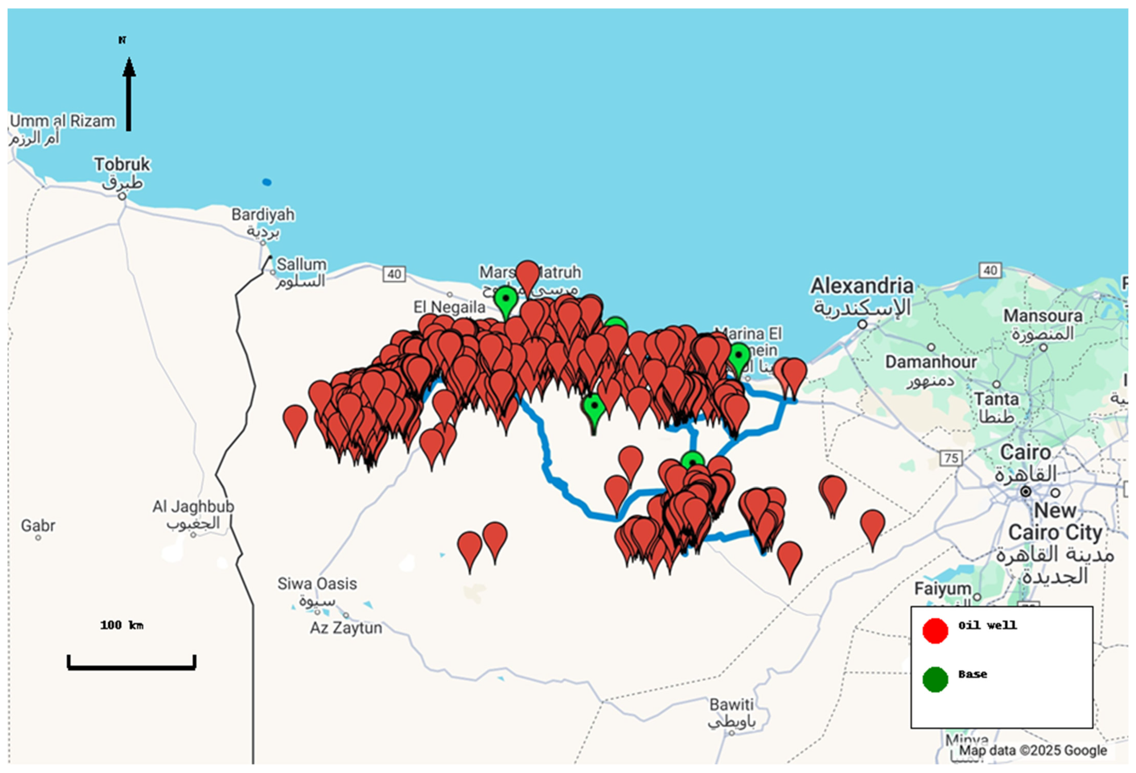
  • Quantitative Data: Field data from over 4000 ESP installations in Egypt’s Western Desert, spanning 10 years of recorded parameters, were collected from an ESP team, engineering databases, workover records, and failure investigation reports (DIFA). These data provide a reliable and diverse foundation for identifying failure patterns and trends.
  • Qualitative Data: A thorough literature review was conducted to identify gaps and inconsistencies in existing ESP failure classifications. The literature review highlighted the mix up between failure modes and root causes and led to the development of a structured framework that clearly distinguishes between failure modes and root causes.
Data Collection
The two types of data were collected to aid in developing the two-step integrated classification system. These data included the following:
  • Field Data: Failure records from ESP installations, including failure modes, root causes, operational conditions, and troubleshooting logs were extracted from engineering databases and database systems.
  • Literature Data: Existing classifications and failure descriptors from academic and industry sources were reviewed to identify gaps and inconsistencies.
Development of a Novel Integrated Failure Modes and Root Cause (IFMRC) Two-step Classification
Both the collected data and failure analysis classification from the literature were used to develop the new two-step failure classification system. The new classification system has two steps, which are explained below.
Step 1. Failure Mode Classification (Figure 1)
Benefits of using Failure Mode Classification: The proposed classification offers several key advantages. It ensures comprehensive coverage by addressing a broad spectrum of failure modes, including electrical, mechanical, hydraulic, chemical, and environmental and operational factors. Focusing on component-level failures enhances diagnostic precision and enables targeted interventions by linking specific component issues to broader failure modes. The system is highly applicable in maintenance and design, aiding in root cause analysis and identifying vulnerabilities in ESP components, ultimately improving reliability. With its applicability in both academic research and practical field operations, this classification system fosters a deeper understanding and more effective mitigation of ESP failures. A detailed description of the failure modes and their respective subcategories and components can be found in Appendix A.
Step 2. Root Cause Failure Classification (Figure 2)
Benefits of the Root Cause classification: The root cause classification is focused on failure mechanisms, recognizing that multiple factors can contribute to a single failure mode, thus enabling a thorough root cause analysis (RCA) and effective corrective action planning. It is practical for field applications, allowing the identification of primary failure factors, which supports targeted prevention strategies, enhances troubleshooting accuracy, and reduces downtime. This approach also supports continuous improvement by fostering a deep understanding of failure mechanisms, leading to advancements in ESP design, manufacturing, operations, and maintenance, ultimately enhancing system reliability and performance. A detailed description of the root causes and their respective subcategories can be found in Appendix B.
Justification for the proposed two-step classification:
The two-step classification offers a comprehensive analysis of failure mechanisms, considering the interconnectedness of ESP subsystems. By categorizing failures into electrical, mechanical, hydraulic, chemical, and operational types, it provides a holistic view that aids engineers in design, operation, and maintenance. It enhances predictive maintenance by identifying failure interactions, leading to more precise strategies. The system improves diagnostics by focusing troubleshooting efforts on the relevant components, such as motors or cables for electrical failures. By identifying root causes, it enables effective remediation and drives systematic investigation. It supports design optimization by highlighting failure interaction points and improving operational parameters to prevent issues like gas lock. Targeted safety measures are implemented for each failure type, and cost efficiency is achieved by addressing the most common failures with targeted solutions. The system standardizes knowledge transfer and training, providing a common language for engineers, while facilitating benchmarking and performance evaluation to drive continuous improvement. These classifications go beyond theoretical concepts as they offer practical frameworks that enhance the reliability, efficiency, and safety of ESP systems.
Development of the Classification Framework
The framework was developed in two steps, supported by a fishbone chart and flowchart for clarity of failure identification and classification, as shown in Figure 3 and Figure 4, respectively.
The fishbone chart shown in Figure 3 provides a visual representation of different failure types categorized based on their underlying root causes. It follows a structured skeleton, starting with failure modes at the top, branching into specific failure categories, and leading toward failure classification on the right. The structured hierarchy helps in identifying how failures originate.
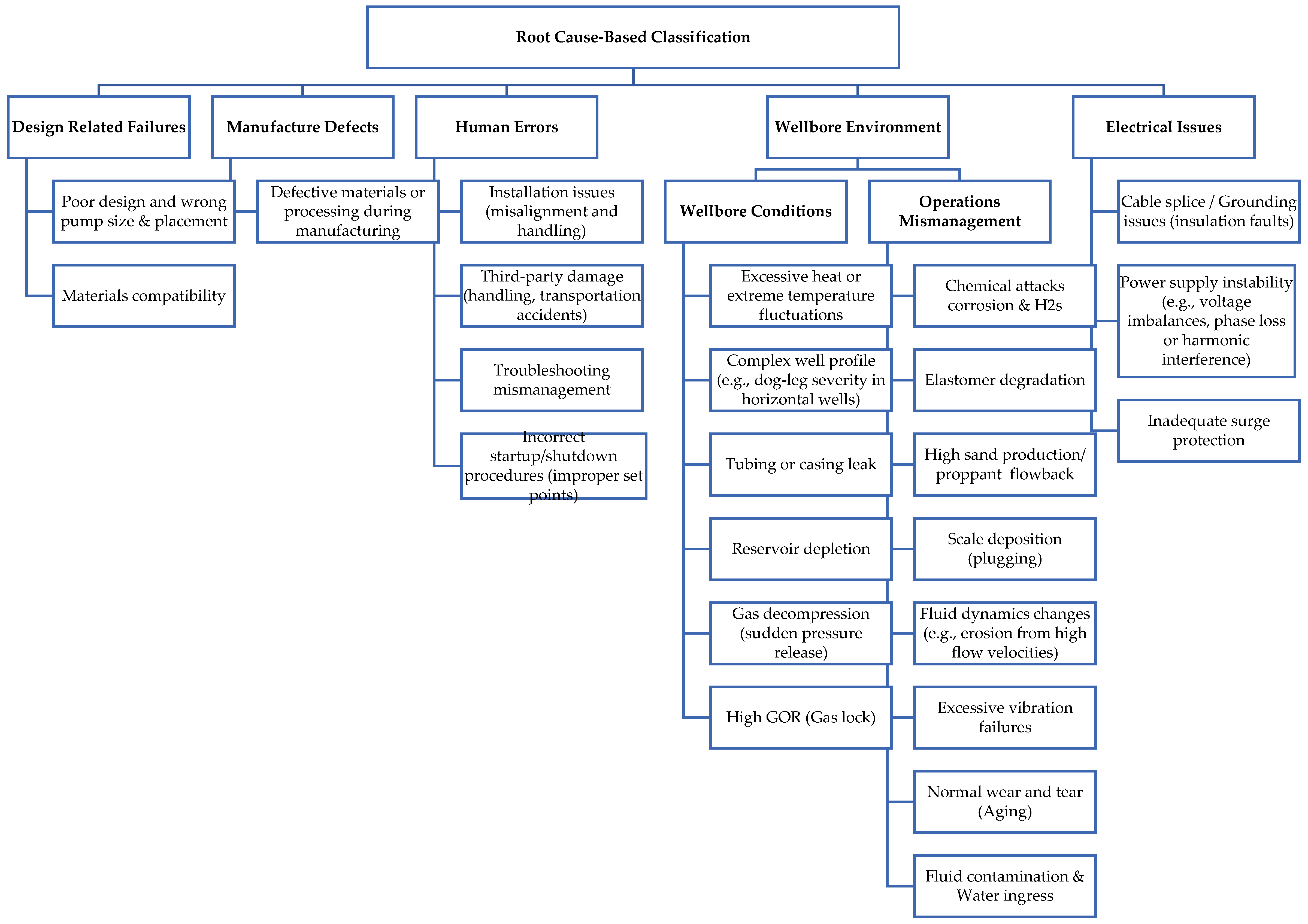
  • Root Causes (leftmost box) serve as the fundamental sources of failures; these causes may be directly causing the failure, or multiple interrelated factors may be contributing to a failure.
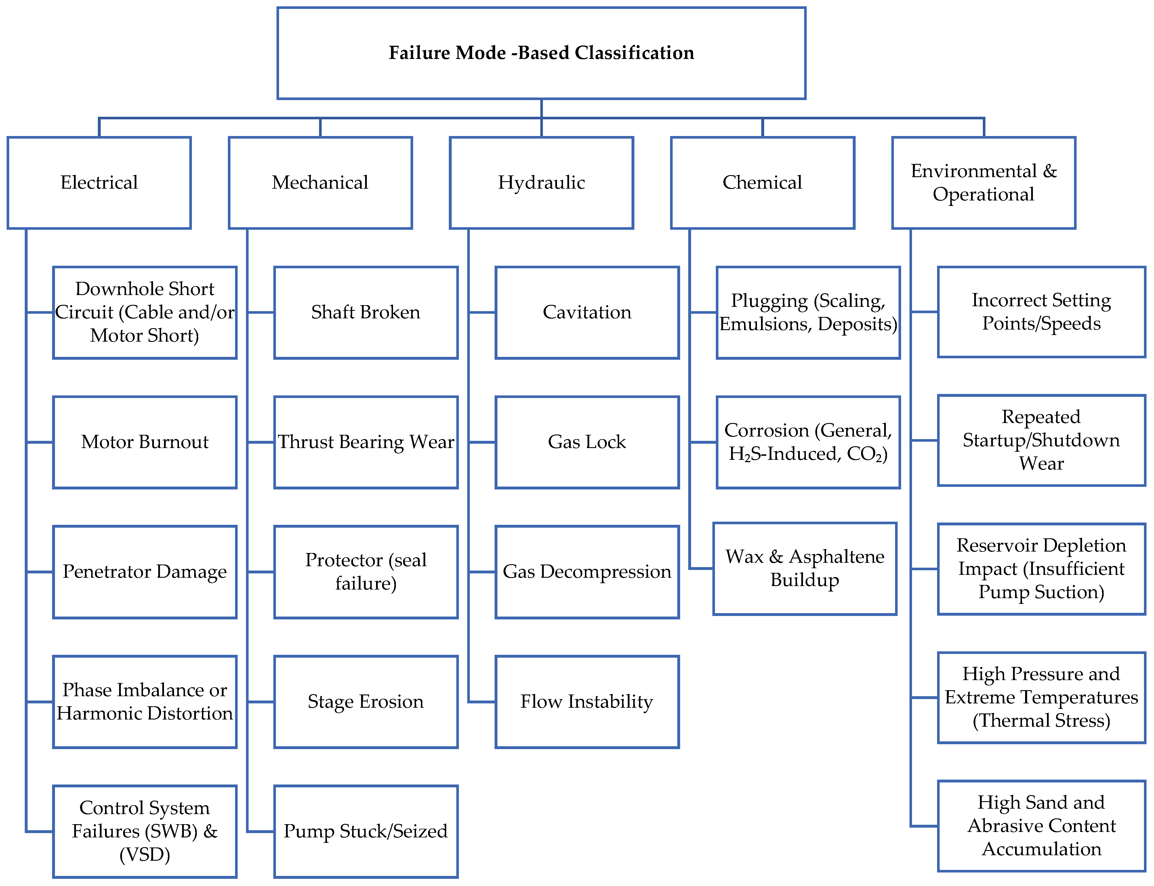
  • Failure Categories include the following:
  • Chemical Failures (e.g., corrosion, chemical attacks).
  • Mechanical Failures (e.g., stuck pump, broken shaft).
  • Electrical Failures (e.g., power surges, cable short circuits).
  • Hydraulic Failures (e.g., fluid pressure issues, seal degradation).
  • Environmental Failures (e.g., extreme temperatures, high sand and abrasive content).
  • Operational Failures (e.g., human errors, repeated startup/shutdown).
This diagram can be used in risk assessment, root cause analysis (RCA), and failure mode and effects analysis to systematically identify, classify, and prevent failures in the oilfield.
The flowchart in Figure 4 guides the process of diagnosing and analyzing pump failure events through structured steps:
  • Pump Down Notification—Identify an issue requiring investigation.
  • Data Collection—Gather relevant operational data and obtain a failure potential from history.
  • Failure Event Decision:
  • Pump Up? → System resumes normal operation.
  • Pump Down? → Failure event occurred.
4
Failure Analysis:
  • Step 1: Identify the failure mode.
  • Step 2: Determine the root cause.
5
Documentation and Action—Findings are recorded in a report and used as input for modeling to improve system reliability.
This structured approach ensures a systematic diagnosis of pump failures, helping with troubleshooting, documentation, and predictive maintenance.
The classification was applied to a case study of over 4000 ESP installations in Egypt’s Western Desert, where failure modes and root causes were systematically analyzed. The dataset reflects a wide range of operating conditions, including varying well depths, pump settings from shallow to deep, and diverse corrosive environments, including high-H2S wells. Statistical methods were used to assess the consistency and reliability of the classification. While the framework aligned well with real-world data, limitations such as incomplete root cause analysis records and subjective failure descriptions were encountered. These challenges emphasize the need for improved data quality and the need for a classification that distinguishes between failure modes and root causes.
The proposed classification improves upon existing frameworks by offering broader applicability and finer granularity. Unlike traditional classifications that often conflate failure modes and root causes, this framework clearly distinguishes between the two, enabling more precise diagnostics. Additionally, it incorporates modern operational challenges, such as high sand production and gas lock, which are not adequately addressed in older systems. The integration of both qualitative and quantitative data also sets this framework apart, making it more adaptable to diverse operational environments.
Western Desert Case Study: Applying the Proposed Two-Step Classification
In this case study, we examine more than 4000+ installations across the Western Desert, distributed over the full extension of the Western Desert in Egypt (see map in Figure 5). Reported workovers: in the examined dataset, there were more than four thousand workovers. Data were collected from multiple sources, including the ESP database, drilling and workover well records, and insights from the engineering team’s field database. Additionally, this was supplemented with office-generated annual failure reports and (DIFA) reports, ensuring a comprehensive and well-rounded dataset for analysis. Notice that out of 4000 ESP installations, a total of 3190 records show ESPs that stopped operating due to failure and were subsequently pulled. The remaining 800 cases were either manually stopped (not classified as failures) or pulled for reasons unrelated to ESP failure. These non-failure reasons include economic decisions, optional fracturing, pump type changes (e.g., switching to SRP or PCP), ESP upgrades or downgrades, well recompletions, or conversion to injection or water source wells. Additionally, 990 cases were not investigated due to missing or incomplete root cause analysis. To assess the robustness of our conclusions in light of this missing data, we conducted a sensitivity analysis by reassigning the unknown cases to (i) the most frequent root cause and (ii) the least frequent root cause and found no material change in the overall rankings. Furthermore, we evaluated the association between failure modes and root causes using a chi-square test of independence, which yielded a statistic of 342 with 324 degrees of freedom and a p-value of 0.2356—indicating no statistically significant relationship at the 5% level, though the high degrees of freedom warrant cautious interpretation. We also calculated Cramér’s V to assess association strength. The initial result was inflated due to sparsity in the contingency table. After grouping infrequent failure modes into a single “Other” category, the recalculated Cramér’s V was 0.16, indicating a weak association. Therefore, the conclusions of this case study are based on the 2200 cases with complete (DIFA) records and have been tested for sensitivity to data limitations.
Failure Modes
Figure 6 shows the failure modes distribution of ESPs in the WD area, with the frequency of each failure type depicted by the number of occurrences. The most common failure mode is motor short circuit (Motor S.C.), which accounts for over 1000 failures. Low flow follows closely behind, with just under 1000 failure incidents. Round cable short circuit (R-Cable S.C.) also appears frequently but with fewer failures than motor and low flow issues. Pump shaft bearing (Pump Sh. B) failures are moderate in comparison, while tubing hole failures occur less often. The stuck pump is another less frequent failure mode. Penetrator short circuit (Pent. S.C.) and flat cable short circuit (F-Cable S.C.) are among the least common failure types, with very few reported incidents. The others category includes all other failure types such as human errors, but these contribute to a smaller proportion of total failures. Overall, the data emphasize that motor-related and flow-related failures are the primary causes of ESP failures, with cable and pump issues being less prevalent.
Figure 7 highlights the most frequent root causes. The prominence of scale deposition (plugging) and tubing leaks suggests persistent issues related to the wellbore environment and operational mismanagement. Extreme temperature fluctuations and defective manufacturing processes appear to be critical contributors, indicating the need for tighter material selection and operational control. A noticeable cluster of electrical issues (grounding faults, power instability) further emphasize the role of a consistent power supply. This root cause classification refines the failure mode data by excluding non-failure events and correlating observed failure modes with detailed root causes and (DIFA) reports.
Key Observations of the Western Desert Case Study:
This practical case study from oilfields in Egypt clearly highlights the critical challenge of misclassifying non-failure operational modes as failure modes, underscoring the need for precise differentiation in diagnostic and predictive maintenance frameworks, as well as mixing failure observations with root causes, creating confusion and ambiguity that hinders any further analysis of the data. This case study serves as a foundation for conducting a more accurate and in-depth analysis using a two-step classification approach, refined and enriched by integrating data from multiple sources. These challenges emphasize the need for structured classification systems and adaptable approaches to effectively address ESP failures. The case study shows the importance of enhancing (DIFA) coverage. Despite the diverse range of failure modes recorded in ESP systems, only a subset undergoes dismantle, inspection, and failure analysis (DIFA), with root cause analysis (RCA) performed for just 2200 cases due to operational and logistical challenges. Expanding (DIFA) beyond warranty-triggered inspections is crucial for building a comprehensive failure database and improving predictive maintenance. However, operational challenges, such as delayed retrieval of pump strings, decontamination of NORM-exposed systems, and reliance on visible issues like scale deposits, often hinder RCA and (DIFA). Failure modes and root cause analysis highlight critical trends and areas for improvement. Scale deposition (plugging) is the most frequent cause, significantly impairing pump efficiency and triggering secondary failures, such as motor overload and impeller plugging, necessitating prioritized preventive strategies. Tubing or casing leaks, often resulting from corrosion, wear, or sealing issues, underscore the importance of robust materials and inspection protocols. Extreme heat and temperature fluctuations, the third leading cause, highlight the thermal sensitivity of ESP components, particularly motors, emphasizing the need for proper sealing, lubrication, and pump selection based on thermal conditions. Cable failures, including grounding issues and defective materials, point to vulnerabilities in manufacturing and installation, suggesting the need for stricter quality assurance and better training for personnel. Human errors and fluid contamination, such as water ingress, further contribute to failures, which are linked to inadequate training, poor procedures, or ineffective wellbore isolation. Addressing these interconnected issues through tailored operational practices and enhanced preventive measures is critical to mitigating cascading failures.
Figure 8 presents the distribution of Motor S.C. (short circuit) failure cases across various root causes identified in Appendix A. The most dominant contributors include excessive heat or extreme temperature fluctuations, cable splice/grounding issues, and scale deposition. Mechanistically, prolonged exposure to elevated temperatures degrades motor insulation materials, leading to electrical breakdown and eventual short circuits. Similarly, poor cable splicing and grounding defects create direct electrical paths to the ground, resulting in Motor S.C. events. Additionally, internal motor contamination from scale deposition and fluid ingress introduces conductive pathways that further promote short circuiting. This clear association between specific operational and environmental conditions and Motor S.C. failures reinforces the need for improved temperature management, cable handling practices, and fluid control to enhance ESP reliability.
Case Study: Cobra-08—ESP Reliability and Diagnostic Precision with IFMRC
Field Overview:
Cobra-08 is a high-profile vertical well in the Western Desert, targeting the Lower Baharya formation. It initially delivered over 3000 BOPD of naturally flowing crude. After an artificial lift was installed, the well remained productive but began exhibiting performance anomalies and recurrent failures.
Chronology of Events and Failures (Pre-IFMRC):
March–December 2020:
Low flow symptoms emerged twice (Mar–Dec 2020 and Feb–Jun 2021), and each was tied to a suspected tubing or casing leak.
December 2020:
A sudden R-cable short circuit (S.C.) triggered a shutdown.
Production and Electrical Trends:
Over the same timeframe, the ESP data showed rising DHP (downhole pressure) (from ~1000 to 1500 psi), stable WHFP (~80 psi), and gradually dropping current draw, indicating motor loading stress.
Deferred oil production spiked to 65 STB/D, especially during generator-related shutdowns.
IFMRC Diagnostic—What Could Have Changed
If the IFMRC framework had been operational during this period, the following improvements would have likely emerged:
Multifactor Isolation: the recurrence of “Low Flow” issues might not have defaulted to tubing leaks alone.
Domain Mapping via Hierarchical Pathways, using the two-step IFMRC tree:
Failure Mode: Flow instability
Root Causes Considered: Wellbore environment, tubing or casing leak
Expert consensus (with data context) would favor a composite diagnosis over repeated tubing replacement—saving at least one full workover cycle (~30+ days).
Operational Cost Avoidance:
A conservative estimate suggests over 8000 STB of deferred oil could have been avoided.
Reducing unnecessary workovers (estimated USD 150 K each) would have provided tangible cost savings.

3. Discussion

The paper highlights the critical challenge of misclassifying normal operational modes as failures, emphasizing the need for precise differentiation in diagnostic and predictive maintenance systems. It also addresses the issue of conflating failure events with their root causes, leading to confusion and ambiguity that obstructs effective data analysis. The use of two-step classification of ESP failures reveals several interconnected challenges that, when addressed through targeted strategies, can significantly enhance system reliability and performance. Aging, vibration failures, gas decompression, and reservoir depletion highlight the critical need for predictive maintenance tools and advanced diagnostic systems. These tools can preemptively identify and mitigate common failure modes, reducing downtime and operational costs. Among these issues, scale-related failures are particularly prevalent, underscoring the importance of proactive scale management. Real-time downhole monitoring and tailored chemical inhibitors can effectively mitigate scale accumulation. However, the current reliance on manual monitoring processes—such as monthly fluid sampling and delayed laboratory analysis—often results in outdated data and suboptimal chemical treatment. Implementing SCADA systems and downhole capillary injection systems would enable real-time adjustments, reducing over- or undertreatment by over 40% and minimizing unplanned workover costs.
Motor short circuit (Motor S.C.) is the most frequent failure mode in the dataset, indicating potential issues with motor design, overheating, or electrical instability. Root causes could include poor insulation, excessive heat, or voltage fluctuations. They may also be linked to fluid contamination, scale deposition, or operational mismanagement, which can exacerbate motor stress and lead to short circuits. The high frequency of stuck pump failures suggests issues such as scale deposition, sand production, or mechanical wear. These failures are often caused by improper fluid handling or inadequate maintenance. Chemical injection practices or reservoir depletion could also contribute to this failure mode by altering fluid properties or increasing debris in the wellbore.
Chemical incompatibility further complicates these challenges, accounting for 20% of failures due to unanticipated reactions like scaling or emulsion formation scale deposition, which is a significant challenge in ESP systems, leading to various failure modes, such as tubing and pump plugging, reduced pump efficiency, motor overheating, increased wear and tear, stuck equipment, corrosion under deposit, electrical failures, excessive vibration, reduced productivity, and sensor malfunctions. To mitigate these issues, operators can employ a combination of chemical inhibition, mechanical removal, acidizing, water chemistry management, and real-time monitoring. Additionally, optimizing flow velocities, using scale-resistant materials, and conducting periodic cleaning and maintenance are crucial. By proactively addressing scale deposition through these strategies, operators can minimize downtime, enhance system reliability, and maintain efficient production rates, ultimately extending the lifespan of ESP systems and reducing operational costs.
Manufacturing defects and inadequate quality control (QC) further exacerbate the problem, leading to early equipment failures. Strengthening material inspections, reliability testing, and standardized quality assessments at the manufacturing stage can improve operational longevity. Additionally, high-frequency causes such as tubing or casing leaks, excessive heat, and cable issues rank prominently after scale deposition. Addressing these challenges requires robust design, better material selection, and enhanced installation protocols. Ensuring a reliable power supply, regular maintenance of gensets, and daily well surveys to adjust parameters can reduce frequent start–stop cycles and electrical issues.
By addressing interconnected challenges through targeted preventive measures, advanced monitoring systems, and improved operational practices, operators can significantly enhance ESP reliability, reduce costs, and achieve sustainable production targets. This comprehensive approach not only mitigates immediate failure risks but also fosters long-term operational efficiency and safety. The integration of AI and machine learning into the IFMRC framework can further enhance its predictive and diagnostic capabilities by leveraging historical failure data to anticipate and prevent ESP failures. AI models can automate root cause analysis, detect real-time anomalies, and recommend prescriptive maintenance actions, reducing downtime and operational costs. Predictive maintenance systems and digital twins can optimize performance by simulating operational scenarios and enabling early issue detection. Despite challenges like data quality and implementation costs, AI integration can probably transform the IFMRC framework into a proactive tool, improving ESP reliability, efficiency, and sustainability in oil production.

4. Conclusions

This paper presents a new two-step failure classification method for ESP wells. The classification was applied on a dataset that included more than 4000 ESP installations. Based on the work conducted in this paper, the following conclusions can be drawn:
  • The proposed two-step classification system provides a holistic view of ESP failures by integrating interconnected subsystems. It encompasses previous literature classifications, enhances diagnostic accuracy, eliminates confusion, and supports efficient troubleshooting and root cause identification. The framework also standardizes knowledge transfer, enabling personnel to better anticipate, detect, and manage failures.
  • The two-step classification system includes five failure modes and five main root cause categories, with some root causes contributing to different types of failures. This makes the framework general and applicable to various environments beyond the Western Desert case history. It can be extended to offshore operations and unconventional reservoirs with appropriate contextual validation.
  • The two-step classification was applied to a large dataset from the Western Desert, comprising over 4000 failure events from more than 350 wells over a 10-year monitoring period. Several benefits were observed, including improved failure analysis and more targeted remediation strategies.
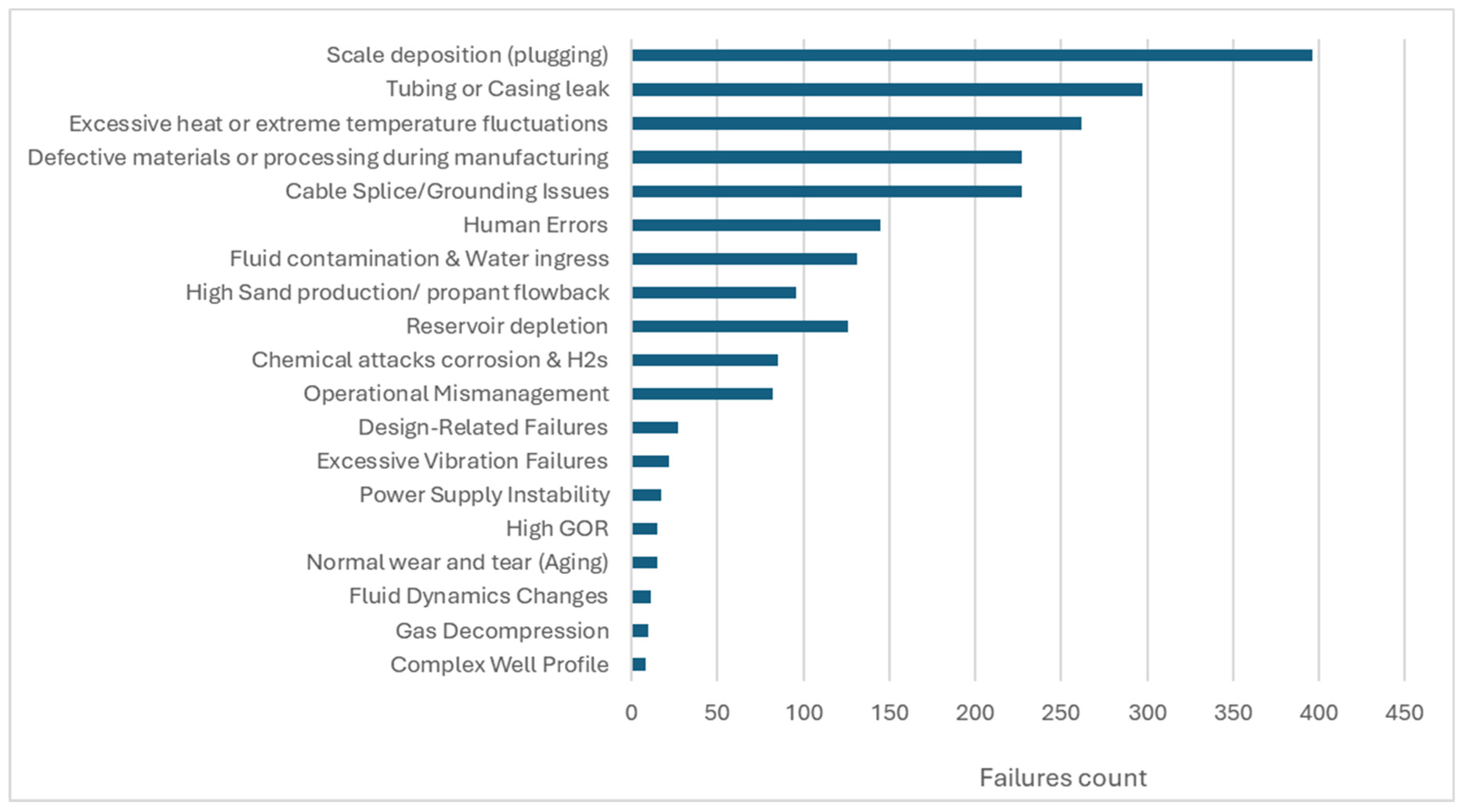
  • The case history reveals that failure modes are rarely caused by a single root cause but are often the result of multiple contributing factors. A detailed root cause analysis, combined with proactive maintenance and operational improvements, is crucial to addressing these failures effectively.
  • Applying the two-step classification revealed that issues with chemical injection practices in the case history led to a significant number of failures. This was identified as a prominent root cause, and remedial actions are currently underway to address the problem based on the case study.
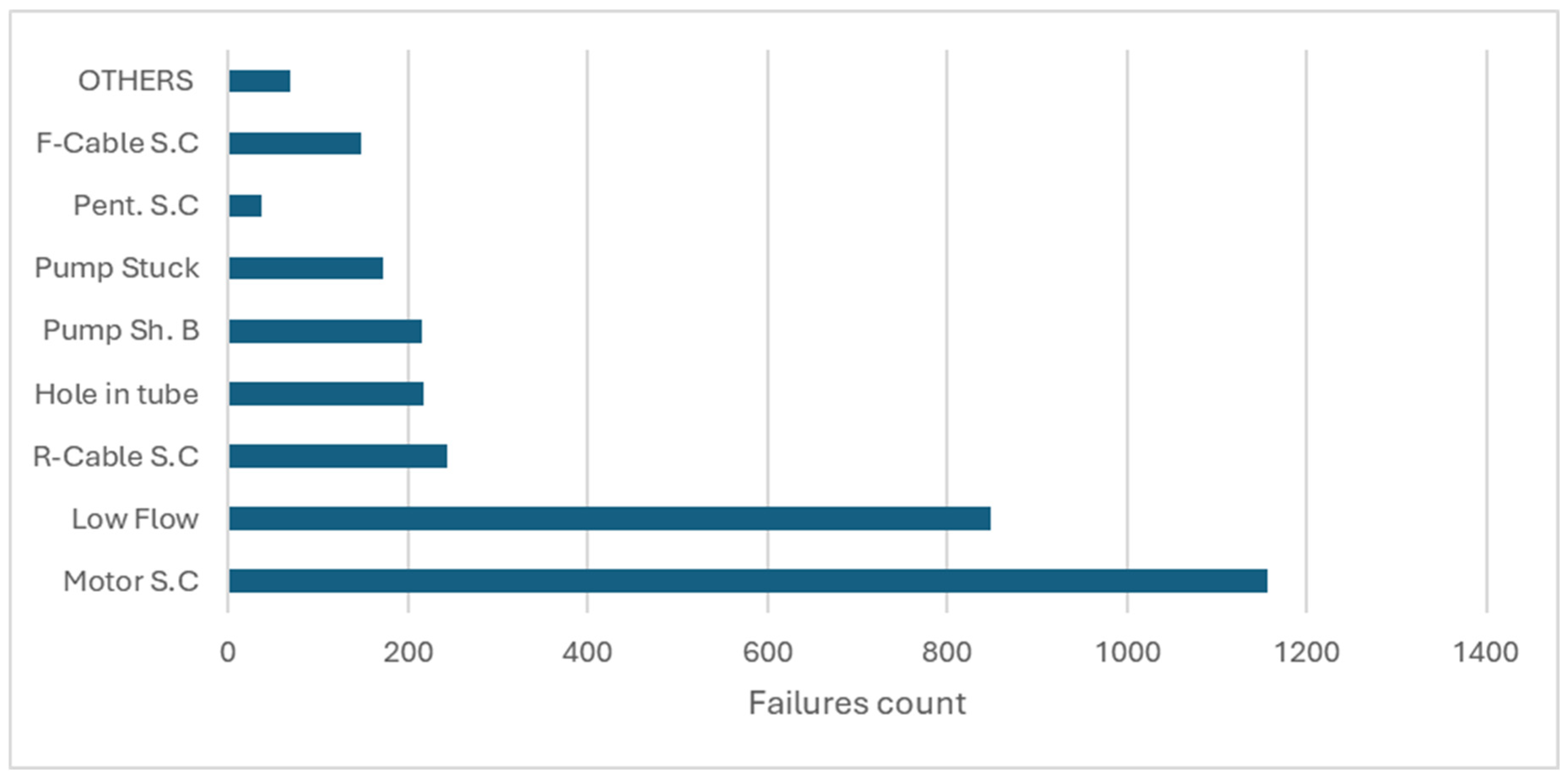
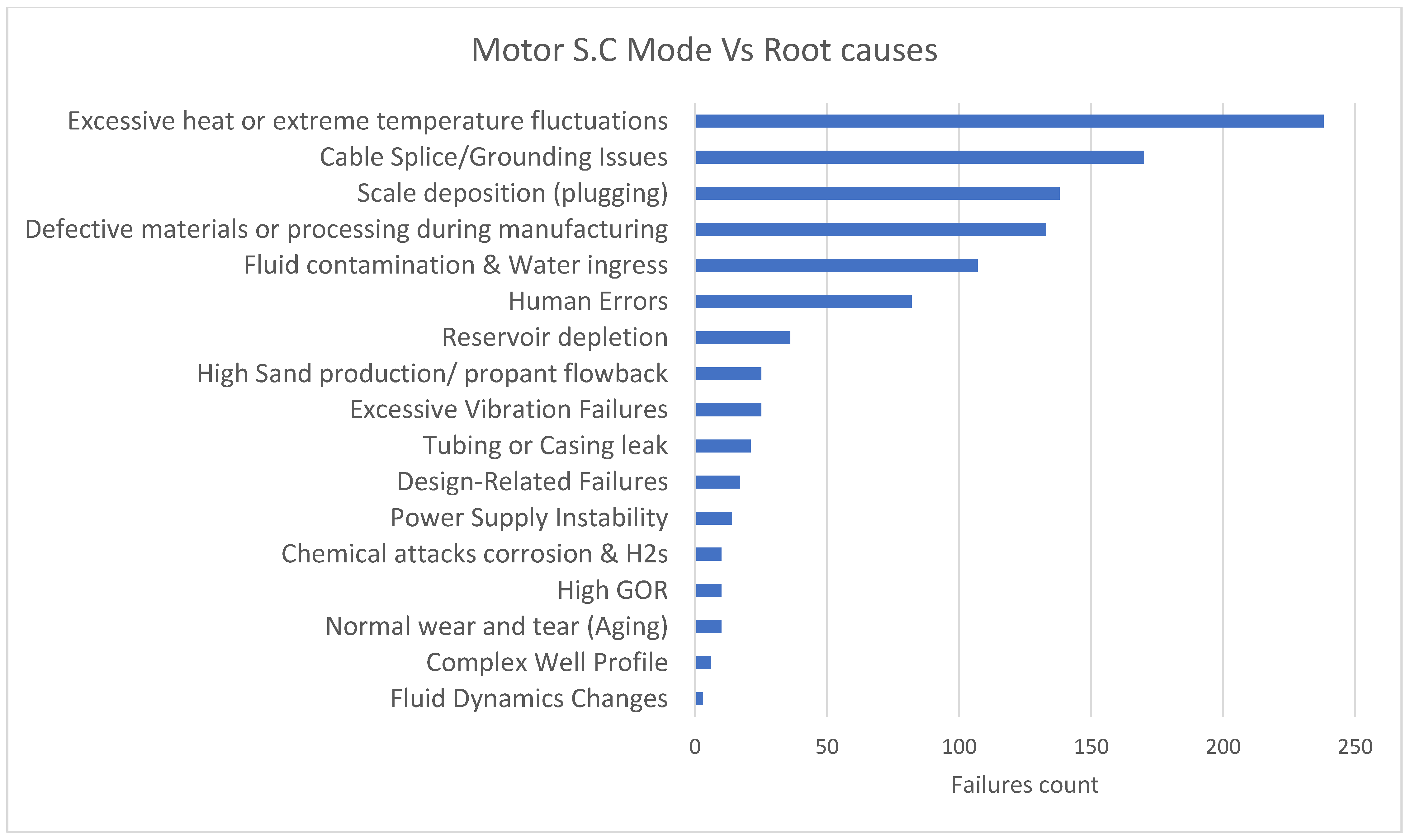
  • Based on the findings of the case study, the motor short circuit was identified as a major failure mode, primarily driven by excessive heat and temperature fluctuations. These thermal stresses emerged as the dominant contributing root cause, leading to motor insulation degradation and eventual burnout.
  • Some failure modes are complicated and require deep analysis. For example, motor short circuits should be accompanied by (DIFA) to better understand the root causes and enable effective remedial actions.

Author Contributions

Conceptualization, M.A.S. and A.H.E.-B.; methodology, M.A.S. and A.H.E.-B.; validation, M.A.S. and A.H.E.-B.; formal analysis, M.A.S.; investigation, M.A.S.; resources, M.A.S.; data curation, M.A.S.; writing—original draft preparation, M.A.S.; writing—review and editing. M.A.S. and A.H.E.-B.; visualization, M.A.S.; supervision, A.H.E.-B. and G.M.H.; project administration, M.A.S.; funding acquisition, M.A.S., G.M.H. and A.H.E.-B. All authors have read and agreed to the published version of the manuscript.

Funding

This research was funded by the American University in Cairo Graduate Student Research Support Grant.

Data Availability Statement

The data presented in this study are available on request from the corresponding author due to confidentiality reasons.

Acknowledgments

I would like to acknowledge and thank the AUC Funding: Grant For publication. I am deeply grateful to Ahmed EL-banbi and Gehad Hegazy for their invaluable guidance and mentorship throughout this study. Additionally, I extend my sincere appreciation to my family and friends for their unwavering encouragement and support.

Conflicts of Interest

The authors declare no conflict of interest.

Abbreviations

AIArtificial Intelligence
APIAmerican Petroleum Institute
BPDBarrel Per Day
CAPEXCapital Expenditure
CNNsConvolution Neural Networks
CO2Carbon Dioxide
DAEDenoising Autoencoders
DIFADismantle, Inspection, and Failure Analysis
DHSHDownhole Short
EGPCEgyptian General Petroleum Corporation
EPFEarly Production Facility
ESPsElectrical Submersible Pumps
F-CableFlat Cable
FRACFracture Stimulation
GORGas/Oil Ratio
G.S.Sh. BGas Separator Shaft broken
H2SHydrogen Sulfide
IFMRCIntegrated Failure Modes and Root Cause
ISOInternational Organization for Standardization
LPROLow Production
LSTMLong Short-Term Memory
MLEMotor Lead Extension
MTBFMean Time Between Failures
NORMNaturally Occurring Radioactive Material
OHTLOverhead Tower Line
OPEXOperating Expenditure
PCAPrincipal Component Analysis
PCPProgressive Cavity Pump
POFFProduction Off
PSIPound Per Square Inch
QCQuality Control
RCARoot Cause Analysis
RCFCRoot Cause-Based Failure Classification
R-CableRound Cable
S.CShort Circuit
Sh. BShaft Broken
SRPSucker Rod Pump
SWBSwitch Board
TBGTubing
VSDVariable Speed Drive
WAGWater Alternating Gas

Appendix A. Failure Mode Classification

Table A1. Failure mode classification.
CategorySubcategoryDescriptionExamplesApplication/Importance
Electrical FailuresDownhole short circuit and grounding issues.Insulation breakdown leading to short circuits. These failures typically happen in critical components such as the motor windings, power cables round to flat splices or round to round splices, motor lead extensions (MLE), or penetrators. They can have severe operational consequences, leading to shutdowns, workovers, or early equipment replacements.In a study by on offshore wells in Saudi Arabia, 50% of the electrical failures were caused by downhole short circuits in the motor lead extension (MLE) beneath the packer. The extreme environmental conditions, including high salinity and high temperatures, contributed to cable degradation and short circuits.
Poor grounding leads to electrical faults or damage.
Production Downtime: Short circuits cause immediate ESP shutdown, halting production and necessitating costly workovers.
Power cable is often the single most costly component of the ESP system. When it has been correctly matched to the operating environment and handled with care it can provide years of service and often may be fit for re-use even though other mechanical components of the ESP system may have failed
Motor BurntOverheating of motor windings causing permanent damage or leading to short circuits.Excessive current drawing, poor cooling, elevated temperatures, or harmonic interference.Impacts motor lifespan, requiring frequent replacements or workovers.
Control System Failures (SWB) and (VSD)Failures related to the control systems that manage the operation of the ESP. This includes issues with variable frequency drives (VFDs), programmable logic controllers (PLCs), and other electronic control components such as fuse blown.VFD malfunctions, PLC programming errors, and sensor failures.Equipment Damage: Prolonged electrical faults can damage the motor and associated equipment, reducing the lifespan of ESP components.
Safety Risks: Short circuits in gas-producing wells pose significant fire and explosion hazards, making prevention and detection critical.
Penetrator DamagePhysical damage to electrical penetrators in wellbore or corrosion can cause short circuits.Cracked penetrator seals, water ingress in cables.Essential to ensure electrical integrity and prevent hazardous leaks.
Phase Imbalance/Harmonic DistortionFailures due to electrical noise or interference that affects the control systems and communication within the ESP system. This can lead to erratic operation or failure of sensitive electronic components.
Voltage imbalance across phases, harmonic interference from power supply affecting motor performance.
Interference from nearby power lines, electrical noise from variable frequency drives (VFDs), and voltage spikes causing control system malfunctions.
Erratic Voltage spikes/drops causing motor stalling and electrical failures.
Ensure smooth motor operation and protect against premature burnout. Essential for ensuring stable power delivery to ESPs.
Use of Sinusoidal VSD Units: Variable Speed Drives (VSDs) with clean sinusoidal output prevent voltage spikes and harmonics that could compromise electrical insulation.
Mechanical FailuresShaft BrokenBreakage or bending or cracks of the shaft caused by fatigue wear, misalignment, or excessive stress and vibrations. It occurs at any point across shaft in (pump, intake, seal or motor).Shaft failure from operational fatigue. Excessive vibration, misalignment, or corrosion.Ensures mechanical integrity and avoids disruptions to the pump’s performance.
Thrust Bearing WearWear, corrosion, or inadequate lubrication leads to bearing seizure, causing rotational issues.Metal fatigue, improper lubrication Bearing seizure resulting in pump breakdown.
Overloading or underloading leads to thrust bearing failure.
Up thrust and down thrust conditions.
Critical for withstanding axial forces from the pump stages.
Critical for the smooth operation of the rotating components to minimize downtime.
Protector/Seal FailureSeal leakage or breakdown caused by extreme pressure, fluid incompatibility, or thermal stress.Seal failure under high pressure leading to fluid intrusion/leaks.Essential for preventing contamination and maintaining the system’s pressure balance. Protects motor components from wellbore fluids, enhancing durability.
Pump Stuck/SeizedMechanical locking of the pump, preventing movement.Foreign object intrusion, scaling deposits like Sand deposits causing pump impeller seizure.Requires immediate intervention to restore operations.
Essential to maintain continuous flow and prevent shutdowns.
Stage erosion
(Impeller Wear/Damage)
Abrasive particles in the fluid (like sand) cause wear on pump components, including impellers and diffusers.Loss of hydraulic efficiency and Impeller vane damage.
Impeller eroded by sand-laden fluid.
Continuous erosion degrades ESP performance and increases the frequency of workovers.
Coupling FailureDamage to couplings connecting motor shafts and pump shafts, often due to misalignment or torque overload.Coupling shearing under excessive torque.Ensures proper power transmission from motor to pump.
Hydraulic FailuresCavitationOccurs when localized pressure within the pump drops below the vapor pressure of the fluid, causing vapor bubbles to form. When bubbles collapse, they damage pump components.Pitting on pump surfaces.
Rapid impeller wear
Critical for pump longevity; cavitation can result in severe mechanical erosion if not detected early.
Gas LockHappens when excessive free gas accumulates in the pump, disrupting the fluid flow. The motor experiences underload due to reduced liquid intake.ESP motor current drops abruptly Insufficient fluid liftReduces efficiency and leads to pump shutdown. Horizontal wells are particularly prone to gas lock issues.
Gas DecompressionDamage caused by sudden gas pressure release.Rapid pressure drops causing explosive effect on cable.Prevents sudden mechanical/electrical failures.
Flow InstabilityFluctuations in flow rate impacting pump performance.Slug flow, rapid flow velocity changes.Maintains steady operation for optimal performance.
ChemicalPlugging
(Scaling)
Deposition of minerals like calcium carbonate, barium sulfate, or iron sulfide on pump surfaces due to changes in temperature or pressure.
Blockages from scaling, emulsions, or wax deposits.
Scale buildup, Blocked impellers and tubing Reduced fluid flow and efficiencyScale inhibitors, acidizing, or mechanical cleaning.
Ensures continuous flow and prevents system downtime.
CorrosionDegradation of metallic components due to chemical reactions with well fluids containing water, oxygen, CO2, or H2S.
Sulfide stress cracking (SSC) and hydrogen embrittlement caused by H2S exposure, especially in sour wells.
Failure of motor seals and cables.
Catastrophic failure of seals and pump shafts.
Corrosion pits in casings and tubing.
Use of corrosion-resistant materials, chemical inhibitors, or cathodic protection. Non-metallic seals and use of H2S-resistant materials.
Wax and Asphaltene BuildupAccumulation of wax and asphaltenes restrict flow.
Formation of stable emulsions or wax deposits within the ESP or tubing, blocking fluid flow.
Formation of deposits in tubing or pump.
Asphaltene precipitation. Impeller clogging Reduced flow efficiency
Reduces flow interruptions and maintains system efficiency.
Use of demulsifies or wax inhibitors.
Environmental and OperationalHigh Sand and AbrasivesSand or solid particles like proppants back flow causing wear and erosion of pump internals.Erosion of impellers due to sand-laden fluids.Important for selecting suitable materials and design modifications to manage abrasive environments.
High Pressure and Extreme TemperaturesExtreme well conditions impact the fluid’s properties and can lead to seal degradation, fluid leaks, and pressure imbalances.
Failures from continuous operation in high or low temperatures beyond design specs.
- Seal failure under pressure
- Lubricant breakdown at high temperatures
Thermal degradation of electrical insulation or including seals, bearings.
Ensuring ESP components are rated for specific well conditions is essential to prevent premature failures.
studies indicate that for every 10 °C increase in temperature, the rate of material degradation can double, leading to reduced lifespan of components [38].
Incorrect Setting Points and Operating SpeedsRunning the ESP at improper speeds or Operation outside the optimal range, leading to inefficiency.
Improper surge protections cause electrical failure.
Operating at sub-optimal conditions affecting performance.Vital for maximizing pump efficiency and preventing damage.
Repeated Startup/Shutdown WearWear caused by frequent cycling of the pump.Excessive startups lead to mechanical stress.Minimizes mechanical fatigue and extends equipment life.

Appendix B. Root Cause-Based Failure Classification

Table A2. Root cause-based failure classification.
Root CauseDescriptionExamplesApplication/Importance
Design-Related FailuresFailures originating from flaws or limitations in the initial design of the ESP system.Inadequate material selection leads to premature corrosion.
Poor design and wrong pump size and placement
Suboptimal Pump Sizing
Incorrect pump selection for well conditions, leading to inefficient operation and excessive wear.
selecting pumps incompatible with well fluids or operational range.
Material Incompatibility: Mismatch between materials and well environment (e.g., high salinity or corrosivity).
Highlights the importance of robust design processes and material selection to avoid inherent weaknesses.
Manufacturing DefectsFailures caused by errors during the manufacturing process, including material defects or assembly errors. Motor winding faults cause short circuits.
Poor welds result in mechanical failures.
Defective materials or processing during manufacturing
Quality Control Issues: Insufficient QA during production.
Welding or Assembly Defects: Inadequate joint strength or misaligned assemblies.
Emphasizes the need for stringent quality control during manufacturing to prevent latent defects.
Human errorsFailures resulting from improper installation practices or alignment issues caused by mistake from by operators, rig crew., technicians, or engineers during any phase of the ESP lifecycle.
Including surveillance teams that monitor pump performance.
Installation Errors: Misalignment of the pump causing excessive vibration and mechanical wear.
Incorrect wiring during installation causing electrical faults.
Troubleshooting mismanagement:
Excessive start and stop or (incorrect set points)
start pump while having back spin causing shaft broken issue.
Monitoring System Neglect: Inaccurate data interpretation or failure to respond to alerts.
Third-Party Damage (Handling Accidents):
1. Transportation Damage: Dropped equipment causing internal misalignments or cracks.
2. Forklift/Crane Damage: Dents or electrical faults caused by mishandling during loading/unloading.
3. Storage Damage: Exposure to moisture or extreme temperatures due to improper storage.
4. Packaging Errors: Inadequate padding during shipping leading to component micro-damage.
5. Accidental Collisions: Damage to equipment during on-site installation from careless handling.
Critical for ensuring that proper installation procedures are followed to avoid early-life failures.
Stresses the need for proper training, oversight, and protocols to minimize the risk of human error.
Wellbore environmentWellbore conditions
Failures caused by external environmental factors such as extreme temperatures, pressures, abrasive particles, or corrosive fluids.
Thermal Degradation: High operating temperatures, either due to poor cooling or Excessive Heat or Extreme Fluctuations: Causes component degradation (motor and seal failures)
Complex Well Profile: Dog-leg severity leads to mechanical stress.
Reservoir Depletion: Impacts pump efficiency.
Pressure Surges: Beyond just decompression, transient pressure spikes can cause component damage
Gas Decompression: Sudden pressure drop causing equipment stress.
Gas Interference: High gas-to-liquid Triggers gas lock or cavitation within the pump, stopping flow.
Or operating the pump at incorrect speeds causing cavitation or gas lock.
High pressure surges (gas decompression)
Tubing or Casing Leak: Causes pressure imbalance and
Inadequate Cooling: Insufficient fluid flow or incorrect operating conditions causing the motor to overheat.
Focuses on the need to consider environmental conditions in the selection and design of ESPs to prevent damage.
Emphasizes the need to understand and manage the fluid dynamics to prevent hydraulic failures.
Operations Mismanagement
Failures due to incorrect operation, including running the pump outside its designed specifications.
Chemical attacks
Reactions between injected chemicals and formation fluids or the materials in ESP components.
H2S Exposure (Sour Gas):
Hydrogen sulfide in well fluids causes rapid corrosion of metallic components, particularly in sour gas wells.
Microbiologically Influenced Corrosion (MIC)
Corrosion caused by sulfate-reducing bacteria (SRB) and other microbes present in the water phase.
Pitting corrosion on pump surfaces
- Biofilm formation blocking fluid paths.
Elastomer Degradation
Breakdown of elastomeric components (such as seals) due to chemical exposure or temperature changes.
Fluid Instability: Wax build-up or emulsions causing flow disruptions.
Fluid Incompatibility: Changes in fluid chemistry can destabilize operations.
- Scale Deposition (Plugging): Reduces flow and efficiency.
- High Sand Production/Proppant Flowback: Causes erosion and blockage.
Fluid Dynamics Changes: Erosion due to high flow velocity
Rapid Startup/Shutdown Cycles: Contributing to wear.
Excessive Vibration Failures: Component fatigue and misalignment.
Bolt and Fastener Failure
Loose or sheared bolts due to vibration or thermal expansion.
Wear Ring Damage:
Damage to wear rings, leading to increased internal leakage between pump stages.
Wear rings eroded from fluid abrasion.
Normal Wear and Tear (Aging): Long-term mechanical degradation, and natural deterioration of components over time.
Fluid Contamination and Water Ingress: Causes motor and seal failures.
Reinforces the importance of adhering to operational parameters for reliable performance.
Focuses on environmental monitoring and operational adjustments to optimize ESP performance.
Highlights the importance of selecting materials resistant to specific chemical environments.
Chemical Incompatibility
- Seal swelling or degradation
- Plugging injection lines
Chemical compatibility testing before injection programs.
Seal failure due to high H2S exposure. Important for sealing integrity and fluid containment.
Vibration Fatigue:
Loosening of bolts and fasteners, shaft misalignment leading to vibration, and bearing damage due to excessive vibration.
Biocide treatments and water quality management.
- Fastener loosening due to excessive vibration. Maintains secure assembly of components.
Important for sustaining pump efficiency and reducing bypass losses.
Electrical Power IssuesFailures caused by power supply problems, including voltage fluctuations, phase imbalance, or electrical faults.Inadequate Surge Protection: Lack of protection from voltage spikes leads to motor burnout.
Power Supply Instability: Voltage imbalances, phase loss affecting system stability.
Grounding Issues: Poor or faulty grounding can cause power disruptions.
Control System Failures: Malfunction of VSDs or sensors affecting motor control.
Highlights the necessity of stable and clean power supply for maintaining the integrity of electrical components.

Appendix C. Crosswalk Between API RP 11S1 Code and IFMRC Framework

Table A3. Crosswalk between API RP 11S1 code and IFMRC framework.
API CodeAPI DescriptionMapped IFMRC CategoryMapped IFMRC Description
LPROLow ProductionOperational—Reservoir ImpactReservoir depletion or low drawdown
POFFProduction OffElectrical/OperationalPower failure, VSD/SWB trip, or shut-in condition
RSIHResize (Increase Production)Not a failure—Operational Change-
RSDHResize (Decrease Production)Not a failure—Operational Change-
DHSHDownhole ShortElectrical—Downhole Short CircuitCable or motor insulation breakdown
LPUMLocked PumpMechanical—Pump Stuck/SeizedDebris, gas lock, or mechanical jamming
LOAMDrawing Low AmpsElectrical—Control System FailureFaulty VSD setting or underload trip condition
HIAMDrawing High AmpsElectrical—Motor BurnoutHigh load, phase imbalance, or motor overheating
HITBHole in TubingRoot Cause—Wellbore EnvironmentMechanical damage or corrosion leading to leakage
CSRPCasing Repair RequiredRoot Cause—Wellbore EnvironmentCasing deformation, collapse, or corrosion
WKOVWorkoverNot a failure-
STIMStimulation RequiredNot a failure—Reservoir Enhancement-
LOGGLogging Well RequiredNot a failure—Diagnostic Action-
COVTConverting WellNot a failure—Strategic Reuse-
TESTTesting WellNot a failure—Diagnostic Action-
TSPNTemporary Suspending WellNot a failure—Operational Pause-
ABANAbandoning WellNot a failure—Lifecycle Conclusion-
OTH1–5Other (1–5)Various-
7000Splice FailureElectrical—Cable FaultSplice or termination failure
7010Cable FailureElectrical—Cable FaultJacket abrasion, crush, or thermal degradation
7020Motor Flat FailureElectrical—Motor BurnoutElectrical insulation breakdown, winding failure
7030Pigtail FailureElectrical—Connector FaultImproper torque, contact loss, or corrosion
7040Tubing FailureRoot Cause—Wellbore EnvironmentCorrosion, scaling, or mechanical stress failure
7070No Failure, Equip. ChangedNot a failure-
7080UnknownInsufficient data for failure classification-
7090Other FailuresInsufficient data for failure classification

References

  1. Rensburg, N.J.v. Artificial Intelligence Can Reduce ESP Failures. J. Pet. Technol. 2019, 71, 16–17. [Google Scholar] [CrossRef]
  2. Sabaa, A.; Abu El Ela, M.; El-Banbi, A.H.; Sayyouh, M.H.M. Artificial Neural Network Model to Predict Production Rate of Electrical Submersible Pump Wells. SPE Prod. Oper. 2023, 38, 63–72. [Google Scholar] [CrossRef]
  3. Skoko, I.; Lusic, Z.; Pusic, D. Commercial and strategic aspects of the offshore vessels market. Sci. J. Marit. Univ. Szc. 2020, 62, 18–25. [Google Scholar] [CrossRef]
  4. Pastre, L.F.; Fastovets, A. The Evolution of ESP Technology in the North Sea: A Reliability Study Based on Historical Data and Survival Analysis. In Proceedings of the SPE Russian Petroleum Technology Conference, Moscow, Russia, 16–18 October 2017. [Google Scholar]
  5. Vorgutti, S.G.V.; Dixon, D. Artificial Lift Market Global Opportunity Analysis and Industry Forecast, 2022–2029. Available online: https://exactitudeconsultancy.com/reports/4718/artificial-lift-market/ (accessed on 15 January 2025).
  6. Del Pino, J.J.; Martin, J.L.; Vargas, H.; Maldonado, J.S.; Rubiano, E.; Núñez, W.; Sánchez, L.M.; Prada, J.; Gómez, S.; Sarkis, N.; et al. Installation of Electric Submersible Pump as Artificial Lift Method in Low Flow Rate Wells, a Case History. In Proceedings of the SPE Electric Submersible Pump Symposium, The Woodlands, TX, USA, 24–28 April 2017. [Google Scholar]
  7. Ratcliff, D.E.; Gomez, C.; Cetkovic, I.; Madogwe, O. Maximizing Oil Production and Increasing ESP Run Life in a Brownfield Using Real-Time ESP Monitoring and Optimization Software: Rockies Field Case Study. In Proceedings of the SPE Annual Technical Conference and Exhibition, New Orleans, LA, USA, 30 September–2 October 2013. [Google Scholar]
  8. Michael Nirtl, H.H. Sophisticated ESP Sensor Data Analysis and Failure Classification. Master’s Thesis, Petroleum and Geothermal Energy Recovery, University of Leoben, Leoben, Austria, 2017. [Google Scholar]
  9. Alhanati, F.J.S.; Francisco, A.; Sandeep, S.; Solanki, S.C.; Zahacy, T.A.; Todd, Z. ESP Failures: Can We Talk the Same Language? In Proceedings of the SPE Gulf Coast Section Electric Submersible Pump Workshop, Houston, TX, USA, 25–27 April 2001. [Google Scholar] [CrossRef]
  10. Sawaryn, S.J.; Grames, K.N.; Whelehan, O.P. The Analysis and Prediction of Electric Submersible Pump Failures in the Milne Point Field, Alaska. SPE Prod. Facil. 2002, 17, 53–61. [Google Scholar] [CrossRef]
  11. Lapi, S.G.; Arisman, B.; Johnson, M.E. Artificial Lift Performance Enhancements by applying Root Cause Failure Analysis. In Proceedings of the International Petroleum Technology Conference, Kuala Lumpur, Malaysia, 10–12 December 2014. [Google Scholar]
  12. Mubarak, H.A.; Khan, F.A.; Oskay, M.M. ESP Failures/Analysis/Solutions in Divided Zone—Case Study. In Proceedings of the Middle East Oil Show, Manama, Bahrain, 9–12 June 2003. [Google Scholar]
  13. Marra, F.; Girard, C. Advanced Electric Submersible Pumps—Added Value for Offshore Fields. In Proceedings of the SPE Electric Submersible Pump Symposium, The Woodlands, TX, USA, 24–28 April 2017. [Google Scholar]
  14. Alamu, O.A.; Pandya, D.A.; Warner, O.; Debacker, I. ESP Data Analytics: Use of Deep Autoencoders for Intelligent Surveillance of Electric Submersible Pumps. In Proceedings of the Offshore Technology Conference, Houston, TX, USA, 4–7 May 2020. [Google Scholar]
  15. Chad Bremner, G.H.; Kosmala, A.; Nicholson, B. Evolving Technologies: Electrical Submersible Pumps. SLB Artif. Lift 2024, 1. Available online: https://www.slb.com/-/media/files/oilfield-review/p30-43-2 (accessed on 15 April 2025).
  16. Song, Y.; Jun, S.; Nguyen, T.C.; Wang, J. Experimental data-driven model development for ESP failure diagnosis based on the principal component analysis. J. Pet. Explor. Prod. Technol. 2024, 14, 1521–1537. [Google Scholar] [CrossRef]
  17. AlBallam, S.; Karami, H.; Devegowda, D. A Data-Based Reliability Analysis of ESP Failures in Oil Production Wells. J. Energy Power Technol. 2022, 4, 1–29. [Google Scholar] [CrossRef]
  18. ISO 14224:2016; Petroleum, Petrochemical and Natural Gas Industries—Collection and Exchange of Reliability and Maintenance Data for Equipment. ISO: Geneva, Switzerland, 2016.
  19. API RP 11S1; Recommended Practice for the Operation, Maintenance, and Troubleshooting of Electric Submersible Pumps. API: Washington, DC, USA, 2017.
  20. Lea, J.F.; Power, W.J. ESP teardown inspection. Part 6—Here’s what wear and damaging conditions can do. Pet. Eng. Int. 1984, 56, 6413627. [Google Scholar]
  21. Gupta, S.; Saputelli, L.; Nikolaou, M. Applying Big Data Analytics to Detect, Diagnose, and Prevent Impending Failures in Electric Submersible Pumps. In Proceedings of the SPE Annual Technical Conference and Exhibition, Dubai, United Arab Emirates, 26–28 September 2016. [Google Scholar]
  22. Gupta, S.; Nikolaou, M.; Saputelli, L.; Bravo, C. ESP Health Monitoring KPI: A Real-Time Predictive Analytics Application. In Proceedings of the SPE Intelligent Energy International Conference and Exhibition, Aberdeen, UK, 6–8 September 2016. [Google Scholar]
  23. Kalu-Ulu, T.C.; Andrawus, J.A.; George, I.P. Modelling System Failures of Electric Submersible Pumps in Sand Producing Wells. In Proceedings of the Nigeria Annual International Conference and Exhibition, Abuja, Nigeria, 30 July–3 August 2011. [Google Scholar]
  24. Saptadi, S.; Widodo, A.; Athaillah, M.; Ayyasyi, M. Implementation of machine learning methods in predicting failures in electrical submersible pump machines. Multidiscip. Sci. J. 2024, 7, 2025137. [Google Scholar] [CrossRef]
  25. Abdalla, R.; Nikolaev, D.; Gönzi, D.; Manasipov, R.; Schweiger, A.; Stundner, M. Deep Insight into Electrical Submersible Pump Maintenance: A Predictive Approach with Deep Learning. In Proceedings of the SPE Offshore Europe Conference & Exhibition, Aberdeen, UK, 2–5 September 2023. [Google Scholar]
  26. Mello, L.H.S.; Oliveira-Santos, T.; Varejão, F.M.; Ribeiro, M.P.; Rodrigues, A.L. Ensemble of metric learners for improving electrical submersible pump fault diagnosis. J. Pet. Sci. Eng. 2022, 218, 110875. [Google Scholar] [CrossRef]
  27. Takacs, G. Electrical Submersible Pumps Manual: Design, Operations, and Maintenance; Gulf Professional Publishing: Houston, TX, USA, 2017. [Google Scholar]
  28. Thomson, W.T.; Leonard, R.A.; Milne, A.J.; Penman, J. Failure identification of offshore induction motor systems using on-condition monitoring. Reliab. Eng. 1984, 9, 49–64. [Google Scholar] [CrossRef]
  29. Borling, D.C.; Sviderskiy, S.V.; Gorlanov, S.F. Best Practices & Innovations for Improved ESP Performance; Mature Field Case History; TNK-BP Company, Russian Federation. In Proceedings of the SPE Russian Oil and Gas Conference and Exhibition, Moscow, Russia, 26–28 October 2010. [Google Scholar]
  30. Barrios Castellanos, M.; Serpa, A.L.; Biazussi, J.L.; Monte Verde, W.; do Socorro Dias Arrifano Sassim, N. Fault identification using a chain of decision trees in an electrical submersible pump operating in a liquid-gas flow. J. Pet. Sci. Eng. 2020, 184, 106490. [Google Scholar] [CrossRef]
  31. Patri, O.P.; Panangadan, A.V.; Chelmis, C.; McKee, R.G.; Prasanna, V.K. Predicting Failures from Oilfield Sensor Data using Time Series Shapelets. In Proceedings of the SPE Annual Technical Conference and Exhibition, Amsterdam, The Netherlands, 27–29 October 2014. [Google Scholar]
  32. Chen, J.R.; Li, W.; Yang, P.H.; Chen, B.Q.; Li, S. Prediction and classification of faults in electric submersible pumps. AIP Adv. 2022, 12, 045215. [Google Scholar] [CrossRef]
  33. Kimery, D.W.; Saponja, J.C.; Chachula, R.C.; Jensen, C. Breaking the 800 Psi ESP PIP Barrier: How A Proven Flow-Conditioning Technology can Dramatically Improve ESP Performance in Horizontal Wells. In Proceedings of the SPE Electric Submersible Pump Symposium, The Woodlands, TX, USA, 24–28 April 2017; p. D051S014R002. [Google Scholar]
  34. Fakher, S.; Khlaifat, A.; Hossain, M.E.; Nameer, H. Rigorous review of electrical submersible pump failure mechanisms and their mitigation measures. J. Pet. Explor. Prod. Technol. 2021, 11, 3799–3814. [Google Scholar] [CrossRef]
  35. Kannaujia, V.; Bhore, S.P.; Goyal, H.S. Failure Analysis of Submersible Pumps—A Review. In Recent Advances in Industrial Machines and Mechanisms; Springer Nature Singapore: Singapore, 2024; pp. 393–410. [Google Scholar]
  36. EGPC. ESP Failure Classification; EGPC: Cairo, Egypt, 2021. [Google Scholar]
  37. Google LLC. Google Maps [Online]. (2025). Available online: https://www.google.com/maps (accessed on 15 April 2025).
  38. Xiao, J.J.; Lastra, R.A.; Roth, B.A.; Lee, W. Material Overview for Electrical Submersible Pumps: Part I—Metallic and Ceramic Materials. SPE Prod. Oper. 2020, 35, 001–008. [Google Scholar] [CrossRef]
Figure 1. Failure mode-based classification.
Energies 18 03943 g001
Figure 2. Root cause-based failure classification.
Energies 18 03943 g002
Figure 3. Fishbone flowchart of integrated failure modes and root cause (IFMRC).
Energies 18 03943 g003
Figure 4. ESP Failure identification flowchart.
Energies 18 03943 g004
Figure 5. Well distribution across the Western Desert used in the case study. (Map data adapted from ©2025 Google) [37].
Energies 18 03943 g005
Figure 6. Failure modes in the case study from the Western Desert wells.
Energies 18 03943 g006
Figure 7. Root causes in the case study from the Western Desert wells.
Energies 18 03943 g007
Figure 8. Root causes in the case study for Motor S.C. failure mode.
Energies 18 03943 g008
Disclaimer/Publisher’s Note: The statements, opinions and data contained in all publications are solely those of the individual author(s) and contributor(s) and not of MDPI and/or the editor(s). MDPI and/or the editor(s) disclaim responsibility for any injury to people or property resulting from any ideas, methods, instructions or products referred to in the content.

