
Integration Strategies for Large-Scale Renewable Interconnections with Grid Forming and Grid Following Inverters, Capacitor Banks, and Harmonic Filters


Abstract
1. Introduction
- Highlighting the nuances of a carefully planned reactive power study to ensure the inverter reactive power capability along with the main power transformers are adequately sized from an MVAr standpoint.
- Providing a well-balanced set of specification requirements that could be readily used by system developers and utilities for inverter procurement, thereby helping them avoid potential technical omissions or misalignment on inverter specifications.
- Leveraging high-pass harmonic filter design for IBR applications by providing easily replicable examples for these grid filters. In addition, capacitor banks serving as an integral component of harmonic filter solutions are demonstrated to enhance the effectiveness of high-pass filters. They not only provide reactive power compensation but also help in tuning the filter to mitigate specific harmonic frequencies [18,19]. By strategically integrating capacitor banks with high-pass filters, system operators can improve voltage profiles, reduce power losses, and minimize the risk of resonance, thereby ensuring compliance with power quality standards.
2. Reactive Power Capability and Interconnection Requirements
- Confirming with the inverter manufacturer about the selection of the correct active power/reactive power (PQ) capability curves, such that it reflects the accurate capability of the IBRs based on site-specific ambient temperature conditions and interconnection voltage (in p.u.).
- 2.
- Ensuring that the main generator step-up transformer (GSU) is not overloaded in terms of its kVA rating while the reactive power obligation at the POI is maintained for all dispatch levels.
- 3.
- Accounting for the main power transformer’s (MPT’s) and inverter step up transformer’s (SUT’s) no load losses, unless those losses are factored in within the PQ curves being provided by the inverter manufacturers.
- 4.
- Accounting for any station auxiliary loads/seasonal operation and maintenance loads/storage building load.
- 5.
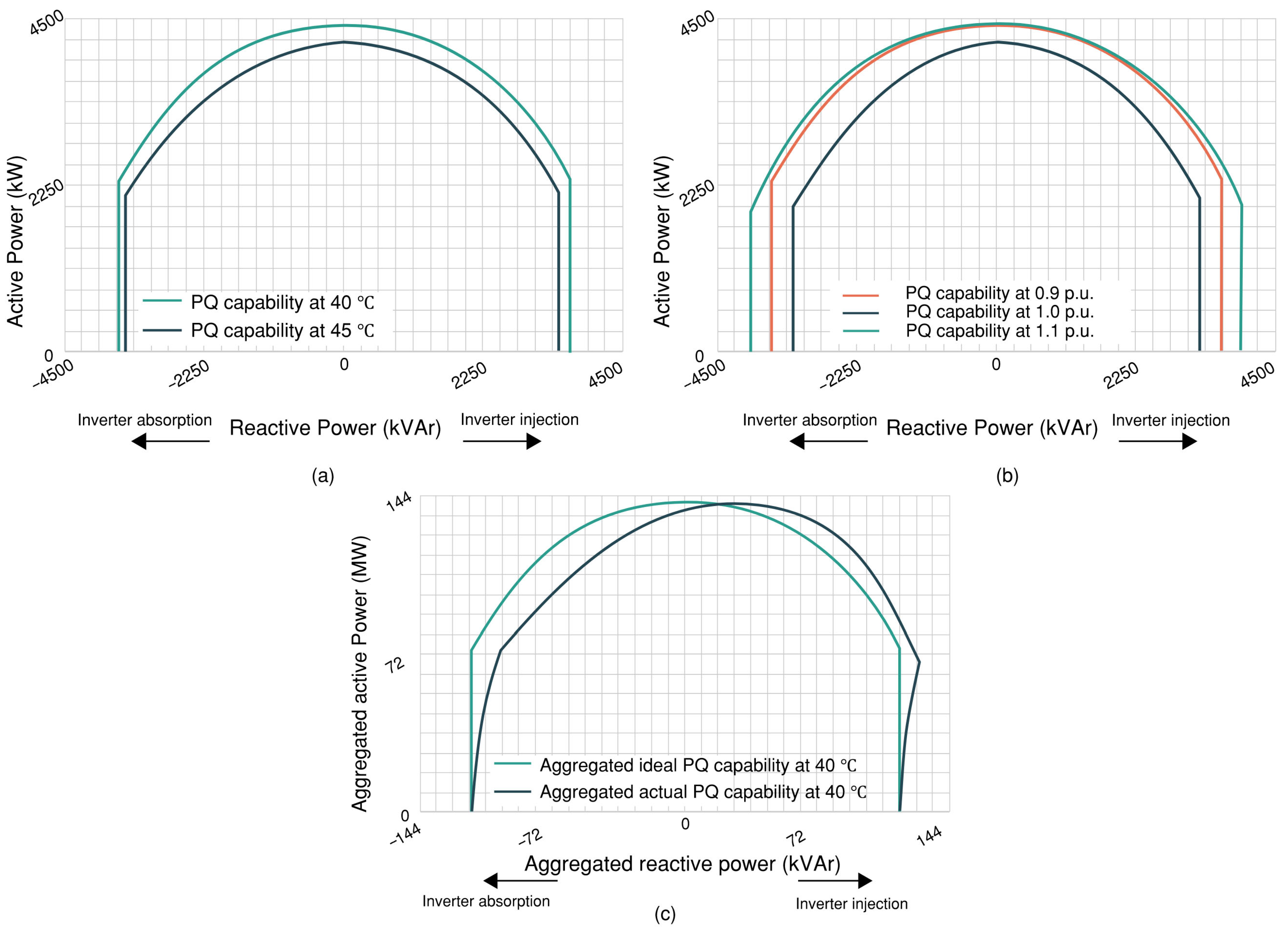
- The need to account for the low voltage and medium voltage feeder cable impedance. As such, with large solar fields typically with a footprint of 500 acres or more, the collector system impedance is sufficient to skew the aggregate PQ curve of the inverters. Such an aggregated PQ curve, with an aggregation of 32 inverters, is shown in Figure 1c.
3. GFM Versus GFL Inverters and Their Controls
4. Technical Specification Details for Grid Inverters and Medium Voltage Step-Up Transformer
- General specifications: These general specifications are fundamental in selecting a grid-scale inverter and highlight the underlying inverter technology and the control modes of the inverter, the power factor requirement that the inverter needs to satisfy, along with the kVA rating of the inverter.
- Inverter control technology: Unlike the GFL mode of control that functions as current sources, which require a phase-locked loop (PLL) and a current–control–loop, and cannot operate without an externally regulated voltage, the GFM mode of operation does not necessitate a PLL. GFMs can regulate their own instantaneous terminal voltages, with a behavior which may be approximated like a voltage source.Utility-scale renewable projects implementing GFM controllers must give due consideration to the IBR’s control system when the parallel operation of multiple GFM inverters is in question. The prevalent parallel operation control strategies (droop control, virtual synchronous generator control, etc.), each with their relevant strength and weakness, are documented in the following section. It is imperative for grid operators and system planners to note that the difference between GFLs and GFMs lies within its control strategy and not in the inverters’ hardware, and as such, the control systems for GFLs can be usually switched to its GFM counterpart mode. However, the transition needs to be seamless, as abrupt changes in the references of both inner control loops and outer control loops, such as the power or voltage loop, may lead to unacceptable deviation in voltages and currents or even compromising safe operations. An excellent reference on the seamless switching between the GFL and GFM control modes may be found here [24]. As of 2025, the GFM controls that are commercially available are the following:
- Advantage—Matured technology with well-documented references on proper tuning of the control parameters. Easy to automate load sharing among a collection of generators.Disadvantage—Lack of inertia support capability.
- Virtual synchronous generator control [27]Advantage—Superior inertia support and hence superior dynamic response.Disadvantage—Prone to oscillations requiring precise parameter tuning.Note—Compensated generalized VSG (CGVSG)-based GFMI and adaptive VSG (AVSG)-based GFMI [28,29,30] are solutions addressing the deficiencies identified in VSG (under scenarios where robust operation cannot be guaranteed under different grid conditions), ensuring the stable operation of GFMIs in both weak and strong grid connections. Both the CGVSG and AVSG are primarily designed to accurately follow power reference signals while delivering the intended dynamic response. This is accomplished by taking into consideration grid parameters during the design phase. The CGVSG employs a lead–lag compensator to guarantee a predefined RoCoF limit and minimized overshoots. In contrast, the VSG structure is adopted by the AVSG; however, its parameters are adaptively tuned based on the real-time estimation of grid impedance. This adaptive approach ensures robust performance across various grid scenarios while adhering to predefined settling time and damping.
- Virtual oscillation control [31]Advantage—Fast response and robust synchronizing capability. Can support island mode of microgrids.Disadvantage—Evolving and relatively complex control algorithm. Can pro duce third harmonic voltage output.
- Matching control [32]Advantage—Fast response and the most robust synchronizing capability among all comparable GFM controls.Disadvantage—Evolving and relatively complex control algorithm.
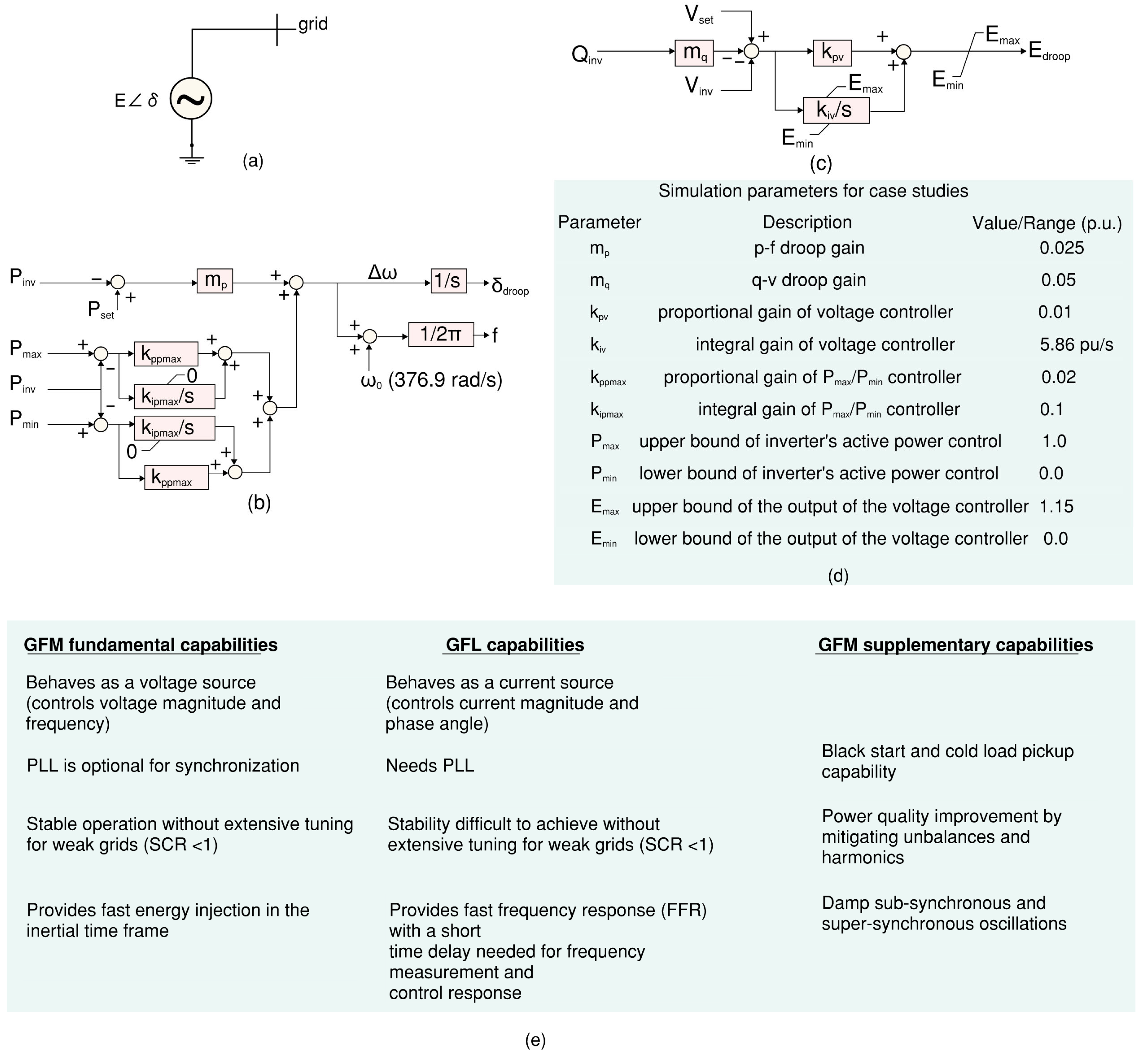
In order to further enhance the collaborative control capability based on inverter resources in complex energy networks, it is possible to consider introducing a cooperative game method to model and coordinate the conflicts of interest between inverter sites, renewable energy, and local load agents under the constraints of shared grid resources, thereby improving the coordination and fairness of system operation [33]. Overall, GFM responds to changes in the grid’s load and generation to keep the synthesized frequency as close as possible to the set nominal value. These controls are robust enough to withstand grid disturbances such as transients, faults, and unexpected load swings, by adapting the internal control parameters to avert system instability. The GFM model used in this study takes advantage of p-f and q-v droop control, with its generic model and control system schematics shown in Figure 4a–c, with Figure 4d docketing the inverter and controller parameters. The outputs of the control system, Edroop and δdroop, are used to establish the IBR internal voltage E∠δE. Some of the main differentiations between the GFM and GFL control are summarized in Figure 4e.Figure 4. Control schematic and simulation parameter for a GFM controller with droop control. (a) Simplistic representation of GFM inverter control. (b,c) P-f and q-v droop control [34]. (d) Simulation control parameter used for the case studies in this manuscript. Note: The p-f droop control guarantees synchronization of phase angles across numerous GFM IBRs, while the q-v droop loop alleviates significant circulation of reactive power between the same group of IBRs. (e) GFM and GFL major difference comparison.Figure 4. Control schematic and simulation parameter for a GFM controller with droop control. (a) Simplistic representation of GFM inverter control. (b,c) P-f and q-v droop control [34]. (d) Simulation control parameter used for the case studies in this manuscript. Note: The p-f droop control guarantees synchronization of phase angles across numerous GFM IBRs, while the q-v droop loop alleviates significant circulation of reactive power between the same group of IBRs. (e) GFM and GFL major difference comparison.![Energies 18 03934 g004]()
- Minimum power rating (kVA) and altitude and temperature derating factor.
- Interconnection power factor requirements.
- Specification of operation mode such as wake up, sleep mode, synchronization, and disconnect.
- Night-time reactive power availability, also known as the “Q at night” feature.Night-time reactive power capability, often referred to as “Q at night”, is an emerging area of interest in the operation of grid-scale inverters. This “Q at night” capability allows inverters to offer reactive power support to a grid even in the absence of solar irradiance, thereby enhancing grid stability and power quality.
- Availability of vendor provided inverter Norton harmonic model. As such, the inverter Norton harmonic model is an important datapoint in additional harmonic filter design as the harmonic model helps one in evaluating the shift of the resonant point of the system as more inverters are added into the system.
- Availability of vendor provided inverter PQ curves specifying the ambient temperature, and inverter terminal voltage.
- Monitoring and control capabilities: These monitoring and control capabilities are deemed secondary capabilities and are largely driven by the owner utility/ developer rather than the regional transmission operator. The specifications that fall in this category are the following:
- Lag-free monitoring of PV system parameters such as voltage, current, power, and energy generation.
- Remote monitoring and control of PV inverters through a centralized SCADA system.
- Capability to implement advanced control strategies such as model predictive or back-stepping sliding control.
- Connectivity to SCADA system via Modbus, Ethernet TCP, or fiber.
- Data management and analytics: The data management and analytics capabilities are mainly driven by the utility and the regional transmission operator control center needs, and these requirements can be broadly summarized as follows:
- Compatibility for efficient data storage and retrieval mechanisms for historical data logging and analysis.
- Ability for integration with cloud-based platforms or edge computing devices for data processing and analytics.
- Ability to adopt lightweight communication protocols and IoT-based technologies to reduce data transmission overhead.
- Grid integration and support functions: The grid integration and support functions are driven by the regional transmission operator, and the obligation it sets on the developer or the interconnecting utility.
- Ability to provide secondary services, such as frequency support and oscillation damping, reactive power control, and active power curtailment.
- Compliance with grid code requirements and distribution network operator (DNO) guidelines.
- Mitigation of power quality concerns, such as harmonics and resonance, through appropriate in-built filter design. Standards such as IEEE 519, UL 1741, and FCC part 15B might apply in connection to utility scale inverter’s harmonic contents and electromagnetic interference limits.
- Reliability and resilience: These requirements usually get cascaded from the project planning stage depending on the projected lifecycle of the project.
- Must be able to perform an average of 50,000–75,000 charging, discharging cycles.
- Robust and fault-tolerant system design to ensure reliable operation and minimize downtime.
- Redundancy and failover mechanisms for critical components.
- Cybersecurity measures (such as network segmentation, secure communication protocols like TLS/SSL) to protect the SCADA system from cyber threats.
- Mean time to repair: 2–4 h per power module.
- Mean time to failure: 10–15 years for 1 inverter power module.
- Protection features: The protection features and functionalities are specified by the protection engineering team to ensure the inverter is compatible with the overall and specific protection schemes in place. For instance, anti-islanding protection is a common feature for grid inverters whereas ground fault monitoring can be performed at the collector station without the need for such monitoring capability in the inverter itself.
- Ground fault monitoring through ground-fault detector interrupter (GFDI).
- Anti-islanding protection, which can be passive, active, or a combination of both. This protection allows detecting island situations and lead to the disconnection of the inverter [35] (thereby preventing it from feeding electricity back into the grid and potentially endangering utility workers who may be repairing lines).
- Flexible frequency protection settings to allow for under/over frequency.
- Grid support including frequency and voltage ride-through and recovery capabilities (within the framework of IEEE 1547 or similar standards), reactive power control, ramp rate, and rapid fault current injection at the POI in case of balanced faults.
- Active heating capability at night where the inverter regulates its internal ambient temperature to prevent condensation, thereby helping with increasing longevity of the internal power electronic devices and controllers.
- Medium voltage step-up transformer parameters: The integration of medium voltage step-up transformer with the inverter, although optional, is preferred by utilities and developers as it streamlines the design of the foundation and overall conduit routing. The specifications for such MV transformers are the following:
- Oil type, cooling type, and allowable transformer configuration, such as integrated dry-type transformer.
- Guaranteed No Load Losses (NLLs) and guaranteed Load Losses (LLs) defined at a certain maximum ambient temperature.
- Harmonic K Factors and indication of compliance to IEEE C57.110 standard. Note that the higher the K-Factor, the greater the overheating caused by the harmonics.
- Tap changer specification capable of operating at a certain percentage above or below nominal voltage at full rating.
5. The Role of High-Pass Harmonic Filters for Utility-Scale Applications and the Filter Design Process
5.1. High-Pass Harmonic Filters for Utility-Scale Applications
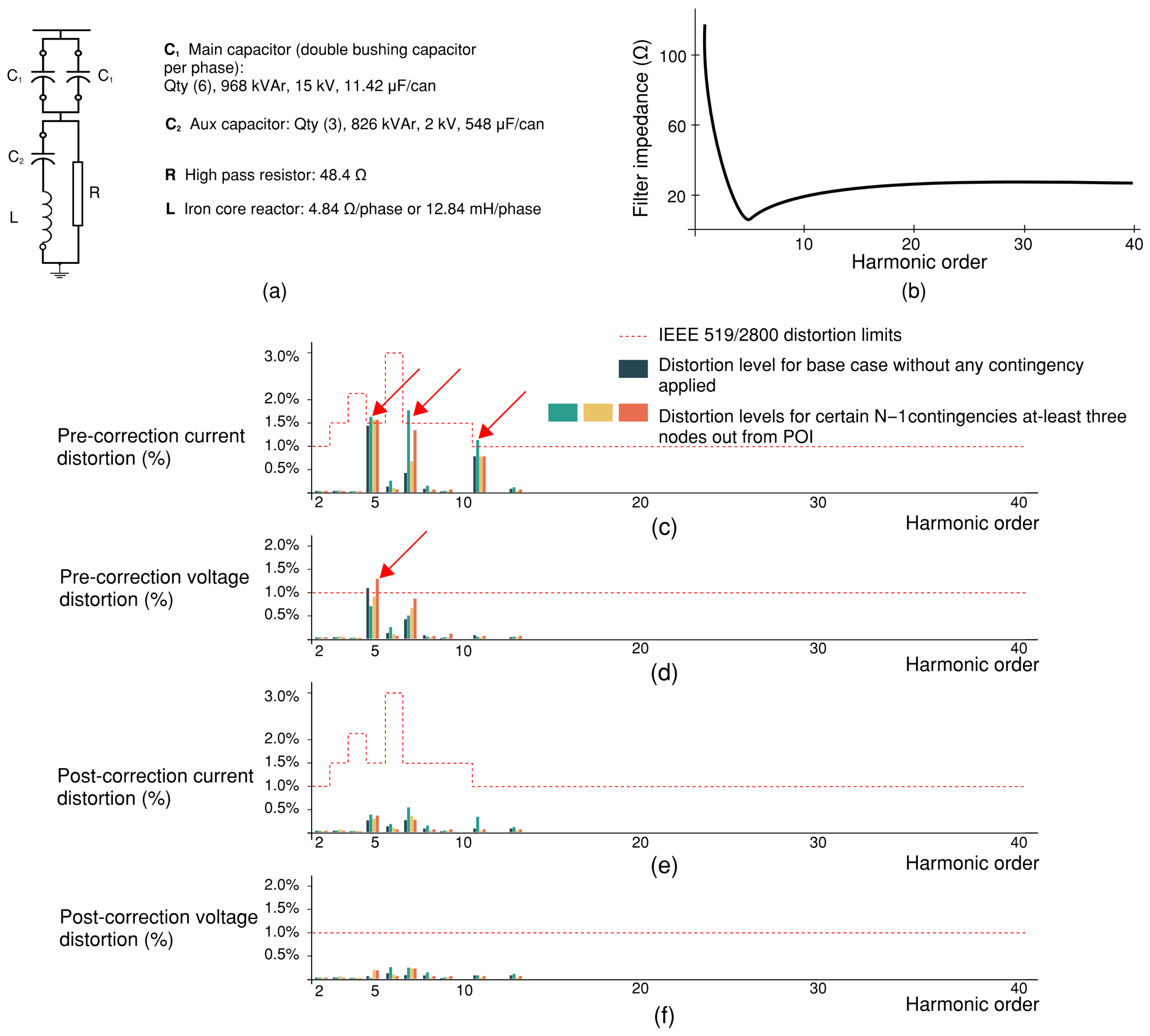
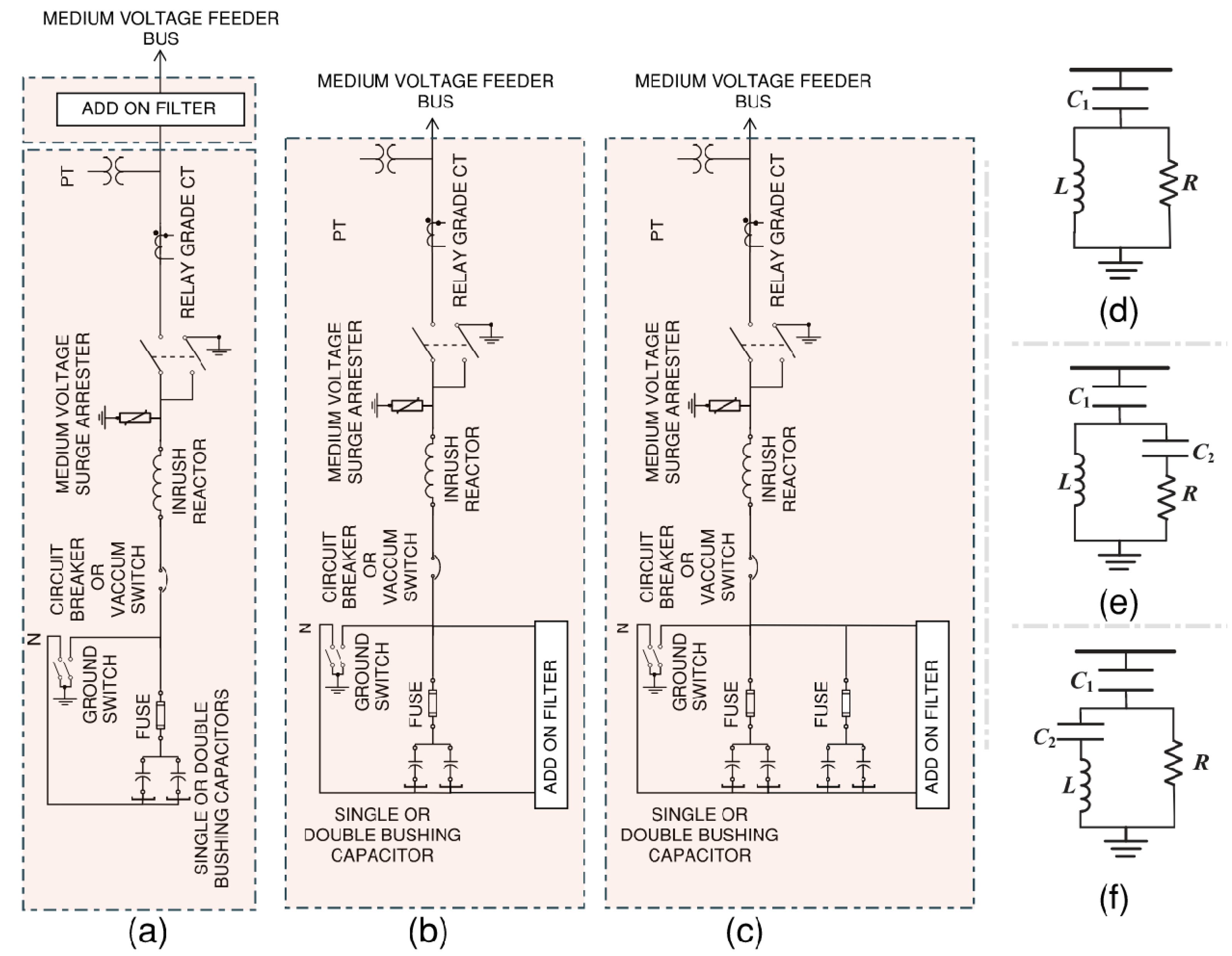
5.1.1. C-Type High Pass Filter Design for Harmonic Mitigation—Methodology and Observation
5.1.2. Notch Filter Design for Harmonic Mitigation—Methodology and Observation
5.2. The Filter Design Process and Leveraging the Presence of a Capacitor Bank for Cost Efficiency
- Vacuum interrupters are typically available in 200 A increments ranging from 200 to 600 A, without any smaller or intermediate ratings. A vacuum switch with a 200 A rating can switch up to 4 MVAr at 13.8 kV. Consequently, to maximize the switch rating, which significantly impacts the cost of the bank, it is advisable to consider a larger step size.
- The kVA ratings for short circuits at medium voltage levels are considerably higher than those of low-voltage systems. As a result, the voltage rise that occurs when capacitor banks are used is significantly reduced, allowing for the use of larger stage sizes.
- The leading power factor is typically not subject to charges by most utilities. Consequently, when power factor penalties are the primary concern, it is more cost effective to use larger stages.
- The equipment ampacity rating at medium voltage levels is relatively low, and copper bus bars are commonly used for most connections. Hence, the interconnection of components at this voltage level is somewhat unrelated to the size of the stage.
6. Summary and Future Scope of Work
- Standardized guidelines for reactive power support: There is a need for clearer, more actionable guidance on leveraging the reactive power capabilities of IBRs, particularly at the point of common coupling (PCC). Such guidelines would help harmonize planning and operational practices across jurisdictions and promote voltage stability in high-penetration scenarios.
- Enhanced IBR modeling frameworks: Current modeling approaches often fall short in capturing the nuanced steady-state and dynamic behaviors of IBRs. Developing models that reflect real-world control interactions, system-level feedback, and grid-forming or grid-following configurations is critical for accurate stability assessments and grid code compliance.
- Nuanced understanding of GFM vs. GFL: The prevailing perception that grid-following (GFL) inverters are inherently less suitable for weak grids compared to grid-forming (GFM) inverters oversimplifies the technological landscape. Future work should focus on advanced tuning methodologies and adaptive control strategies for GFL inverters, particularly under low short-circuit ratio (SCR) conditions, to unlock their full potential in weak-grid applications.
Author Contributions
Funding
Data Availability Statement
Conflicts of Interest
Abbreviations
| GFDI | Ground-fault detector interrupter |
| ERCOT | Electric Reliability Council of Texas |
| FCC | Federal Communications Commission |
| FERC | Federal Energy Regulatory Commission |
| GFL | Grid following (inverter or control) |
| GFM | Grid forming (inverter or control) |
| IBR | Inverter based resource |
| IEEE | Institute of Electrical and Electronics Engineers |
| POI | Point-of-interconnection |
| RES | Renewable energy sources |
| RoCoF | Rate of change of frequency |
| SCADA | Supervisory Control and Data Acquisition |
References
- Alassaf, A.; Alsaleh, I.; Alateeq, A.; Alafnan, H. Grid-following inverter-based resource: Numerical state–space modeling. Sustainability 2023, 15, 8400. [Google Scholar] [CrossRef]
- Ward, L.; Subburaj, A.; Demir, A.; Chamana, M.; Bayne, S.B. Analysis of grid-forming inverter controls for grid-connected and islanded microgrid integration. Sustainability 2024, 16, 2148. [Google Scholar] [CrossRef]
- Ma, F.; Xin, H.; Wu, D.; Liu, Y.; Chen, X. Grid Strength Assessment for 100% Inverter-Based Power Systems via Generalized Short-Circuit Ratio. 2024. Available online: https://www.techrxiv.org/doi/full/10.36227/techrxiv.21120517.v1 (accessed on 4 March 2025).
- Chang, H.; Vanfretti, L. Power hardware-in-the-loop smart inverter testing with distributed energy resource management systems. Electronics 2024, 13, 1866. [Google Scholar] [CrossRef]
- Wang, Z.; Passino, K.M.; Wang, J. Optimal reactive power allocation in large-scale grid-connected photovoltaic systems. J. Optim. Theory Appl. 2015, 167, 761–779. [Google Scholar] [CrossRef]
- Saboori, H.; Pishbahar, H.; Dehghan, S.; Strbac, G.; Amjady, N.; Novosel, D.; Terzija, V. Reactive power implications of penetrating inverter-based renewable and storage resources in future grids toward energy transition—A review. Proc. IEEE 2025, 113, 66–104. [Google Scholar] [CrossRef]
- Grab, R.; Rogalla, S. Symbiotic operation of wind and PV farms connected to the high voltage grid. In Proceedings of the 8th International Symposium on Power Electronics for Distributed Generation Systems (PEDG), Florianopolis, Brazil, 17–20 April 2017. [Google Scholar]
- Fan, B.; Wang, X. Fault recovery analysis of grid-forming inverters with priority-based current limiters. IEEE Trans. Power Syst. 2022, 38, 5102–5112. [Google Scholar] [CrossRef]
- Li, Y.; Gu, Y.; Green, T.C. Revisiting grid-forming and grid-following inverters: A duality theory. IEEE Trans. Power Syst. 2022, 37, 4541–4554. [Google Scholar] [CrossRef]
- Anttila, S.; Döhler, J.S.; Oliveira, J.G.; Boström, C. Grid forming inverters: A Review of the state of the art of key elements for microgrid operation. Energies 2022, 15, 5517. [Google Scholar] [CrossRef]
- Gu, Y.; Green, T.C. Power system stability with a high penetration of inverter-based resources. Proc. IEEE 2022, 111, 832–853. [Google Scholar] [CrossRef]
- Jin, Z.; Wang, X. A DQ-frame asymmetrical virtual impedance control for enhancing transient stability of grid-forming inverters. IEEE Trans. Power Electron. 2021, 37, 4535–4544. [Google Scholar] [CrossRef]
- Salem, Q. Grid-forming inverter control for power sharing in microgrids based on P/F and Q/V droop characteristics. Sustainability 2023, 15, 11712. [Google Scholar] [CrossRef]
- Sharma, D.; Sadeque, F.; Mirafzal, B. Synchronization of inverters in grid forming mode. IEEE Access 2022, 10, 41341–41351. [Google Scholar] [CrossRef]
- Geng, S.; Hiskens, I.A. Unified grid-forming/following inverter control. IEEE Open Access J. Power Energy 2022, 9, 489–500. [Google Scholar] [CrossRef]
- Junesco, D.; Al-Youif, S.; Mnati, M.J.; Tofigh, M.A. Various passive filter designs proposed for harmonic extenuation in industrial distribution systems. Int. J. Eng. Technol. 2018, 7, 75–84. [Google Scholar] [CrossRef]
- Park, B.; Lee, J.; Yoo, H.; Jang, G. Harmonic mitigation using passive harmonic filters: Case study in a steel mill power system. Energies 2021, 14, 2278. [Google Scholar] [CrossRef]
- Alsakati, A.A.; Vaithilingam, C.A.; Prakash, K.S.; Gamboa, R.A.; Jagadeeshwaran, A.; Alnasseir, J. Mitigation of power quality issues in distribution systems using harmonic filters and capacitor banks. Facta Univ.-Ser. Electron. Energetics 2021, 34, 589–603. [Google Scholar] [CrossRef]
- Arif, Y. Implementation of hybrid filter for harmonics reduction in non-linear loads. Eduvest-J. Univers. Stud. 2003, 3. [Google Scholar] [CrossRef]
- Alamanda, S.K.; Boddeti, K.K. Relative distance measure arithmetic-based available transfer capability calculation with uncertainty in wind power generation. Int. Trans. Electr. Energy Syst. 2021, 31, e13112. [Google Scholar] [CrossRef]
- Pouresmaeil, E.; Mehrasa, M.; Godina, R.; Vechiu, I.; Rodriguez, R.L.; Catalao, J.P.S. Double synchronous controller for integration of large-scale renewable energy sources into a low-inertia power grid. In Proceedings of the 2017 IEEE PES Innovative Smart Grid Technologies Conference Europe (ISGT-Europe), Turin, Italy, 26–29 September 2017; pp. 1–6. [Google Scholar]
- UNIFI Consortium. UNIFI Specifications for Grid-Forming Inverter-Based Resource—Version 2; UNIFI: Washington, DC, USA, 2024. [Google Scholar]
- Rueda-Torres, J.L.; Annakage, U.; Vournas, C.; Younis, M.R.; Rosso, A.D.; Vance, K.A.; Srivastava, A.; Ajjarapu, V.; Bharati, A.K.; Van Cutsem, T. Evaluation of Voltage Stability Assessment Methodologies in Modern Power Systems with Increased Penetration of Inverter-Based Resources (TR 126). In CIGRE C4/C2.58/IEEE Joing Working Group. 2024. Available online: https://www.e-cigre.org/publications/detail/943-evaluation-of-voltage-stability-assessment-methodologies-in-modern-power-systems-with-high-penetration-of-inverter-based-resources.html (accessed on 3 June 2025).
- Gao, X.; Zhou, D.; Anvari-Moghaddam, A.; Blaabjerg, F. Seamless transitions between grid-following and grid-forming control: A novel switching method. In Proceedings of the 2023 11th International Conference on Power Electronics and ECCE Asia (ICPE 2023—ECCE Asia), Jeju Island, Republic of Korea, 22–25 May 2023; pp. 1154–1160. [Google Scholar]
- Piagi, P.; Lasseter, R.H. Autonomous control of microgrids. In Proceedings of the IEEE Power Engineering Society General Meeting, Montreal, QC, Canada, 18-–22 June 2006. [Google Scholar]
- Du, W.; Tuffner, F.K.; Schneider, K.P.; Lasseter, R.H.; Xie, J.; Chen, Z.; Bhattarai, B. Modeling of grid-forming and grid-following inverters for dynamic simulation of large-scale distribution systems. IEEE Trans. Power Deliv. 2020, 36, 2035–2045. [Google Scholar] [CrossRef]
- Zhong, Q.C. Virtual Synchronous Machines: A unified interface for grid integration. IEEE Power Electron. Mag. 2016, 3, 18–27. [Google Scholar] [CrossRef]
- Mohammed, N.; Udawatte, H.; Zhou, W.; Hill, D.J.; Bahrani, B. Grid-forming inverters: A comparative study of different control strategies in frequency and time domains. IEEE Open J. Ind. Electron. Soc. 2024, 5, 185–214. [Google Scholar] [CrossRef]
- Rathnayake, D.B.; Razzaghi, R.; Bahrani, B. Generalized virtual synchronous generator control design for renewable power systems. IEEE Trans. Sustain. Energy 2022, 13, 1021–1036. [Google Scholar] [CrossRef]
- Mohammed, N.; Ravanji, M.H.; Zhou, W.; Bahrani, B. Online grid impedance estimation-based adaptive control of virtual synchronous generators considering strong and weak grid conditions. IEEE Trans. Sustain. Energy 2022, 14, 673–687. [Google Scholar] [CrossRef]
- Lu, M. Virtual oscillator grid-forming inverters: State of the art, modeling, and stability. IEEE Trans. Power Electron. 2022, 10, 11579–11591. [Google Scholar] [CrossRef]
- Unruh, P.; Nuschke, M.; Strauß, P.; Welck, F. Overview on grid-forming inverter control methods. Energies 2020, 13, 2589. [Google Scholar] [CrossRef]
- Ding, B.; Li, Z.; Li, Z.; Xue, Y.; Chang, X.; Su, J. Cooperative operation for multiagent energy systems integrated with wind, hydrogen, and buildings: An asymmetric Nash bargaining approach. IEEE Trans. Ind. Inform. 2025, 21, 6410–6421. [Google Scholar] [CrossRef]
- Du, W.; Liu, Y.; Tuffner, F.K.; Huang, R.; Huan, Z. Model Specification of Droop-Controlled, Grid-Forming Inverters (GFMDRP_A); Pacific Northwest National Laboratory: Richland, WA, USA, 2024. [Google Scholar]
- Bravo, R.J.; Robles, S.A.; Muljadi, E. Assessing solar PV inverters’ anti-islanding protection. In Proceedings of the 2014 IEEE 40th Photovoltaic Specialists Conference (PVSC), Denver, CO, USA, 8–13 June 2014; pp. 2668–2671. [Google Scholar]
- Khalfalla, H.; Ethni, S.; Shiref, M.; Al-Greer, M.; Pickert, V.; Armstrong, M. Grid impedance estimation for single phase PV grid tide inverter based on statistical signal processing techniques. In Proceedings of the 2018 53rd International Universities Power Engineering Conference (UPEC), Glasgow, UK, 4–7 September 2018; pp. 1–5. [Google Scholar]
- Zhao, Y.; Ren, L.; Lin, G.; Peng, F. Research on the harmonics penetration characteristics of the traction network to three-phase 380 V power system of the traction substation and suppression scheme. IEEE Access 2020, 8, 195359–195369. [Google Scholar] [CrossRef]
- Xu, S.; Wang, Y.; Xiao, X.; Wu, J.; Lv, W. Non-characteristicharmonic resonance in line commutated converters-high-voltage direct current terminals: A practical case study. Int. Trans. Electr. Energy Syst. 2020, 31, e12743. [Google Scholar] [CrossRef]
- Huang, J.; Zhao, Y.; Wang, J.; Zhang, P. A hybrid active damping strategy for improving the adaptability of LCL converter in weak grid. Electronics 2023, 13, 144. [Google Scholar] [CrossRef]
- Rahmani, B.; Li, W. Proposing wavelet-based low-pass filter and input filter to improve transient response of grid-connected photovoltaic systems. Energies 2016, 9, 653. [Google Scholar] [CrossRef]


| Temp for Inverter PQ Curve | Gross MW at GSU Terminal/Net MW at POI 1 | Gross MVAr at GSU Terminal/Net MVAr at POI 2 | Power Factor at POI/ Additional MVAr Needed 3 | Corrected Power Factor and Additional MVAr | MVA at GSU Input Terminal 4 | GSU Overload Status |
|---|---|---|---|---|---|---|
| 40 °C | Gross—139.48 MW (with 32 inverters providing 4359 kW each)/Net—130.5 MW at POI | Gross—26.9 MVAr (with 32 inverters providing 840 kVAr)/Net—19 MVAr at POI | 0.98/Yes | 0.95/19.7 MVAr needed | 142 MVA | GSU overloaded by 7 MVA. Remark—GSU may be re-nameplated if vendor confirms no loss of life for the GSU. |
| 45 °C | Gross—152.5 MW (with 35 inverters providing 4359 kW each)/Net—138.3 MW at POI | Gross—29.4 MVAr (with 35 inverters providing 840 kVAr)/Net—21 MVAr at POI | 0.98/Yes | 0.95/24 MVAr needed | 154.5 MVA | GSU overloaded, by 19.5 MVA. Remark—Set contractual obligation at POI needs to be decreased as GSU is significantly overloaded. |
| Operator, Location, and GFM Technology | Status and OEM | Size (MW) | Timeline |
|---|---|---|---|
| Zenobē Energy–Scotland (GFM BESS) | Under development, SMA (OEM) | Blackhillock 1–200 MW Blackhillock 2–100 MW Kilmarnock 1–200 MW Kilmarnock 2–100 MW Eccles—400 MW | 2024–2026 |
| Vattenfall—Denmark/Germany (GFM offshore wind via STATCOM) | Deployed, Hitachi Energy (OEM) | Kriegers Flak—605 MW | 2018 |
| AEMO—Australia (GFM BESS) | Deployed, Tesla (OEM) | Riverina and Darlington Point—150 MW | 2023 |
| AEMO—Australia (GFM BESS) | Under development, Power Electronics (OEM) | Liddell Battery Park—500 MW | 2025 |
| Pacific Gas & Electric—Oregon, US (GFM Hybrid of wind, solar, battery) | Under development, OEM unknown | Wheatridge Renewable Energy Facility—380 MW | 2026 |
| NESO—Great Britain (GFM BESS) | Under development, Sungrow (OEM) | Hams Hall—350 MW | 2026 |
| Eversource—New York, US (GFM offshore wind via STATCOM) | Deployed, OEM unknown | South Fork Wind—75 MW | 2024 |
| HECO—Hawaii, US (GFM BESS) | Deployed, Tesla (OEM) | Kapolei Energy Storage—185 MW | 2023 |
| HECO—Hawaii, US (GFM PV + BESS) | Deployed, OEM unknown | Waiawa Phase 2 Solar—60 MW | 2024 |
| Kauai Island Utility Cooperative—Hawaii, US (GFM BESS) | Deployed, Tesla (OEM) | Project #1–13 MW | 2018 |
| Input parameters | |
| kVsystem (line to line voltage rating, typically low voltage side of POI GSU) | 13.2 kV |
| kVAreff (reactive power rating of filter stage) | 1500 kVAr |
| htune (filter tuning point, assuming system frequency is 60 Hz) Note: For a three phase six pulse inverter, 5th harmonic is the first dominant odd harmonic | 5 harmonic or (5 × 60) 300 Hz |
| Resistor and iron-core reactor design | |
| 65.6 A | |
| 116.16 Ω/phase | |
| or 12.84 mH/phase | |
| 48.4 Ω (assuming a conservative value of 2.0 for damping factor) | |
| Main and auxiliary capacitor design | |
| kVmain cap rating | 15 kV |
| 1937 kVAr | |
| assuming double bushing capacitor per phase | 968 kVAr |
| kVaux cap rating | 2 kV |
| 826 kVAr | |
| assuming single bushing capacitor per phase | 826 kVAr |
| Input parameters | |
| kVsystem (line to line voltage rating, typically low voltage side of POI GSU) | 13.2 kV |
| kVAreff (reactive power rating of filter stage) | 1500 kVAr |
| htune (filter tuning point, assuming system frequency is 60 Hz) Note: For a three phase six pulse inverter 5th harmonic is the first dominant odd harmonic | 5 harmonic or (5 × 60) 300 Hz |
| Iron-core reactor and fuse design | |
| 65.6 A | |
| 57.4 A | |
| 116.16 Ω/phase | |
| or 12.84 mH/phase | |
| Main capacitor design | |
| kVmain cap rating | 15 kV |
| 1860 kVAr | |
| assuming double bushing capacitor per phase | 930 kVAr |
| Metal-Clad Enclosed Capacitor Bank | V < 15 kV | 15 kV < V < 34.5 kV |
|---|---|---|
| Single stage without filter with future filter provision | $11,650 (1 MVAr) $60,000 (5 MVAr) $300,000 (25 MVAr) $645,000 (50 MVAr) | $14,925 (1 MVAr) $75,000 (5 MVAr) $375,000 (25 MVAr) $856,000 (50 MVAr) |
| Two stages with integrated notch filter tuned | $13,000 (1 MVAr) $70,000 (5 MVAr) $320,000 (25 MVAr) $650,000 (50 MVAr) | $16,500 (1 MVAr) $82,000 (5 MVAr) $410,000 (25 MVAr) $900,000 (50 MVAr) |
| Three stages with integrated notch filter tuned | $18,650 (1 MVAr) $90,250 (5 MVAr) $456,000 (25 MVAr) $930,000 (50 MVAr) | $19,000 (1 MVAr $95,000 (5 MVAr) $475,000 (25 MVAr) $995,000 (50 MVAr) |
| Four stages with integrated notch filter tuned | $20,000 (1 MVAr) $100,000 (5 MVAr) $535,000 (25 MVAr) $1,100,000 (50 MVAr) | $23,000 (1 MVAr) $120,000 (5 MVAr) $600,000 (25 MVAr) $1,200,000 (50 MVAr) |
| Two stages with integrated C-type high-pass harmonic filter | $15,050 (1 MVAr) $80,450 (5 MVAr) $350,250 (25 MVAr) $795,000 (50 MVAr) | $18,000 (1 MVAr) $85,500 (5 MVAr) $470,000 (25 MVAr) $1,050,000 (50 MVAr) |
| Three stages with integrated C-type high-pass harmonic filter | $19,090 (1 MVAr) $100,450 (5 MVAr) $512,000 (25 MVAr) $1,220,000 (50 MVAr) | $20,950 (1 MVAr) $110,000 (5 MVAr) $625,000 (25 MVAr) $1,300,000 (50 MVAr) |
| Four stages with integrated C-type high-pass harmonic filter | $22,000 (1 MVAr) $101,000 (5 MVAr) $495,500 (25 MVAr) $1,250,000 (50 MVAr) | $24,000 (1 MVAr) $110,250 (5 MVAr) $625,000 (25 MVAr) $1,455,000 (50 MVAr) |
Disclaimer/Publisher’s Note: The statements, opinions and data contained in all publications are solely those of the individual author(s) and contributor(s) and not of MDPI and/or the editor(s). MDPI and/or the editor(s) disclaim responsibility for any injury to people or property resulting from any ideas, methods, instructions or products referred to in the content. |
© 2025 by the authors. Licensee MDPI, Basel, Switzerland. This article is an open access article distributed under the terms and conditions of the Creative Commons Attribution (CC BY) license (https://creativecommons.org/licenses/by/4.0/).
Share and Cite
Ghosh, S.; Bohra, A.; Dutta, S.; Verma, S. Integration Strategies for Large-Scale Renewable Interconnections with Grid Forming and Grid Following Inverters, Capacitor Banks, and Harmonic Filters. Energies 2025, 18, 3934. https://doi.org/10.3390/en18153934
Ghosh S, Bohra A, Dutta S, Verma S. Integration Strategies for Large-Scale Renewable Interconnections with Grid Forming and Grid Following Inverters, Capacitor Banks, and Harmonic Filters. Energies. 2025; 18(15):3934. https://doi.org/10.3390/en18153934
Chicago/Turabian StyleGhosh, Soham, Arpit Bohra, Sreejata Dutta, and Saurav Verma. 2025. "Integration Strategies for Large-Scale Renewable Interconnections with Grid Forming and Grid Following Inverters, Capacitor Banks, and Harmonic Filters" Energies 18, no. 15: 3934. https://doi.org/10.3390/en18153934
APA StyleGhosh, S., Bohra, A., Dutta, S., & Verma, S. (2025). Integration Strategies for Large-Scale Renewable Interconnections with Grid Forming and Grid Following Inverters, Capacitor Banks, and Harmonic Filters. Energies, 18(15), 3934. https://doi.org/10.3390/en18153934