Review

Key Factors, Degradation Mechanisms, and Optimization Strategies for SCO2 Heat Transfer in Microchannels: A Review

1
Department of Engineering, China University of Petroleum-Beijing at Karamay, Karamay 834000, China
2
Xinjiang Key Laboratory of Multi-Medium Pipeline Safety Transportation, Urumqi 830011, China
*
Author to whom correspondence should be addressed.
These authors contribute equally to this work.
Energies 2025, 18(14), 3864; https://doi.org/10.3390/en18143864
Submission received: 27 May 2025 / Revised: 10 July 2025 / Accepted: 14 July 2025 / Published: 20 July 2025
(This article belongs to the Section J1: Heat and Mass Transfer)

Abstract

Despite a growing body of research on supercritical carbon dioxide (SCO2) heat transfer in microchannels, comprehensive reviews remain scarce. Existing studies predominantly focus on isolated experiments or simulations, yielding inconsistent findings and lacking a unified theory or optimization framework. This review systematically consolidates recent SCO2 microchannel heat transfer advancements, emphasizing key performance factors, degradation mechanisms, and optimization strategies. We critically analyze over 260 studies (1962–2024), evaluating the experimental and numerical methodologies, heat transfer deterioration (HTD) phenomena, and efficiency enhancement techniques. Key challenges include the complexity of heat transfer mechanisms, discrepancies in experimental outcomes, and the absence of standardized evaluation criteria. Future research directions involve refining predictive models, developing mitigation strategies for HTD, and optimizing microchannel geometries to enhance thermal performance. This work not only integrates the current knowledge but also provides actionable insights for advancing SCO2-based technologies in energy systems.

1. Introduction

With the global energy demand continuously increasing and the global shift toward sustainable energy solutions, the need for advanced energy technologies that are capable of improving efficiency and reducing carbon footprints is more critical than ever. SCO2, as a new type of working medium, has shown broad application prospects in many high-efficiency energy systems because of its excellent thermal and physical properties [1], such as guiding industrial production [2], nuclear energy [3], coal-fired power generation [4], and waste heat recovery [5]. For example, the energy consumption of a SCO2 coal-fired power generation system was reduced to 10.48 MJ/kWh, and the energy recovery rate was 34.37%, exceeding that of the USC coal-fired power generation system [4]. Industrial waste heat recovery achieves a 9.6% conversion of waste heat for power generation in large engines through the compact Bretton cycle [6]. Especially in the context of miniaturization and high efficiency, SCO2, combined with microchannel technology, offers a promising solution for efficient heat transfer and energy conversion systems [7]. However, although the research in this field has made some progress, there are still some key problems to be solved.
This combination of SCO2 and microchannel technology holds the potential to revolutionize energy systems by improving heat exchange processes, increasing energy efficiency, and reducing environmental impacts. As a future cornerstone of energy technologies, SCO2 microchannels could play a vital role in advancing critical sectors, including power generation, thermal management, and carbon-neutral energy systems. With ongoing research into optimizing SCO2 heat transfer and addressing the challenges posed by heat transfer degradation, the continued development of this field is expected to drive innovation in energy solutions that are both environmentally friendly and cost-effective. The ongoing exploration of SCO2 in microchannel systems represents not just a technical breakthrough, but also a key step towards the realization of a more sustainable, energy-efficient future.
Currently, there are a numerous challenges in the study of the heat transfer process involving supercritical carbon dioxide (supercritical CO2, SCO2) within microchannels [8]. In contrast to conventional fluids, supercritical CO2 (SCO2) exhibits drastic thermophysical property variations across the critical region [9], inducing highly nonlinear heat transfer responses, characterized by pseudocritical anomalies and thermal-lag phenomena under confinement conditions [10]. The deterioration of thermal transport characteristics in SCO2-laden microchannels may trigger cascading thermofluidic instabilities [11], manifesting as thermal oscillations and localized hot spots that compromise the structural integrity of heat exchange components, ultimately destabilizing the thermal management architecture through off-design operation thresholds. Current research efforts in SCO2 heat transfer optimization face fundamental methodological challenges, as the development of reliable multi-objective frameworks necessitates resolving critical knowledge gaps in coupled thermophysical phenomena and scaling law validations under transient operating conditions. The Bergles technique typically categorizes improved convective heat transfer technologies into passive and active enhanced heat transfer technologies [12]. In practical applications, passive enhanced heat transfer technology, such as an enhanced tube, is mostly used.
Recent technological advancements in non-invasive sensing techniques such as high-speed interferometry, microscale thermocouple arrays, near-critical refractive index matching, and laser-induced fluorescence temperature measurement have greatly enhanced our understanding of the hydrothermal force phenomenon of SCO2 in constrained geometry. These tools are crucial for solving complex pseudocritical boundary layer dynamics and characterizing the flow behavior of microchannels under supercritical conditions. On this basis, the numerical study on a horizontal tube by Kurizenga et al. [13] and the experimental study by Pettersen et al. [14] proved the enhancement of the heat transfer (HTC > 8 kW/m2K) through the pseudo-boiling mechanism in the microchannel, clarifying the key aspects of the thermodynamics of SCO2. An important insight drawn from this work is that the profound influence of the microchannel topology, size scaling, and flow direction on thermal performance is controlled by the geometric thermal coupling effect [15]. Furthermore, studies consistently emphasize that hydrothermal deterioration intensifies near the critical point under high pressure, characterized by sudden heat transfer deterioration driven by strong pressure–temperature coupling [16], prompting people to explore mitigation strategies such as baffles [17] and heat flux density regulation, and to enhance the thermohydraulic performance of SCO2 through geometric thermal coupling mechanisms [18].
While extensive reviews exist on SCO2 heat transfer, the current scholarship predominantly prioritizes macroscale heat exchanger designs, leaving comprehensive analyses of microscale thermohydraulic phenomena in confined geometries critically underrepresented [19]. Recent advances in microscale thermal–hydraulic research have driven the development of novel experimental methodologies for probing SCO2 heat transfer dynamics, employing non-intrusive optical diagnostics and high-resolution thermographic techniques to resolve pseudocritical boundary layer transitions in microchannels with hydraulic diameters ranging from 100 to 500 μm. For example, Thielens et al. [20] primarily discuss the waste heat recovery performance of SCO2 in their review. In their study of SCO2 heat transfer properties, Niu et al. [21] investigate rectangular cooling tubes under conditions of elevated mass flow rates and high heat flux densities. In the field of SCO2 heat transfer, there is a significant lack of systematic review publications on the heat transfer process in microchannels. This shortage impedes a comprehensive understanding of the heat transfer mechanism, heat transfer degradation, and development of optimization strategies for enhancing the efficiency of SCO2 heat transfer in microchannels. Therefore, such articles are needed to fill the gaps in the existing literature and promote the in-depth development of related research.
In order to discuss the research progress on SCO2 heat transfer in microchannels more comprehensively, we conducted a comprehensive review of the research results in terms of aspects such as the heat transfer mechanism, high-temperature phase transition mechanism, and heat transfer efficiency optimization methods of SCO2 microchannels. Based on this, we presented our own insights and suggestions for future research on the disputes and unresolved issues in the current literature. These suggestions provide new ideas for better understanding how SCO2 transfers heat in microchannels and lay the groundwork for creating consistent standards and improvement plans in the future. Our perspectives and recommendations aim to advance the field further and provide theoretical support for enhancing the heat transfer efficiency of SCO2 in engineering applications. Accordingly, this review will highlight key challenges in current research and propose directions for future studies.
The structure of this paper is organized as follows: Section 2 will provide a detailed introduction to the thermodynamic properties of SCO2, especially its dramatic changes in properties in the supercritical state. Section 3 reviews the heat transfer experiments of SCO2 in microchannels, with a focus on the heat transfer characteristics in horizontal and vertical microchannels. Section 4 will investigate the HTD phenomenon of SCO2, analyzing its mechanisms and influencing factor and proposing corresponding mitigation strategies. Section 5 outlines the current progress in improving the efficiency of SCO2 heat transfer and suggests potential future optimization directions. The article will summarize the current research status of the entire field and provide some valuable suggestions for future research. Through authoring this paper, we aim to provide a systematic theoretical foundation and technical guidance for SCO2 research on microchannels, thereby further advancing the development of this field.

2. Thermodynamic Properties of Supercritical Carbon Dioxide

SCO2 has been widely studied because of its unique thermal properties and high thermal efficiency. When carbon dioxide surpasses its critical temperature of 304.25 K and critical pressure of 7.38 MPa, the performance of SCO2 changes nonlinearly with the temperature and pressure [22], at which point it exhibits characteristics between those of a gas and liquid. Figure 1 presents the pressure–temperature (P-T) phase diagram of CO2, illustrating the gas, liquid, solid, and supercritical phases.
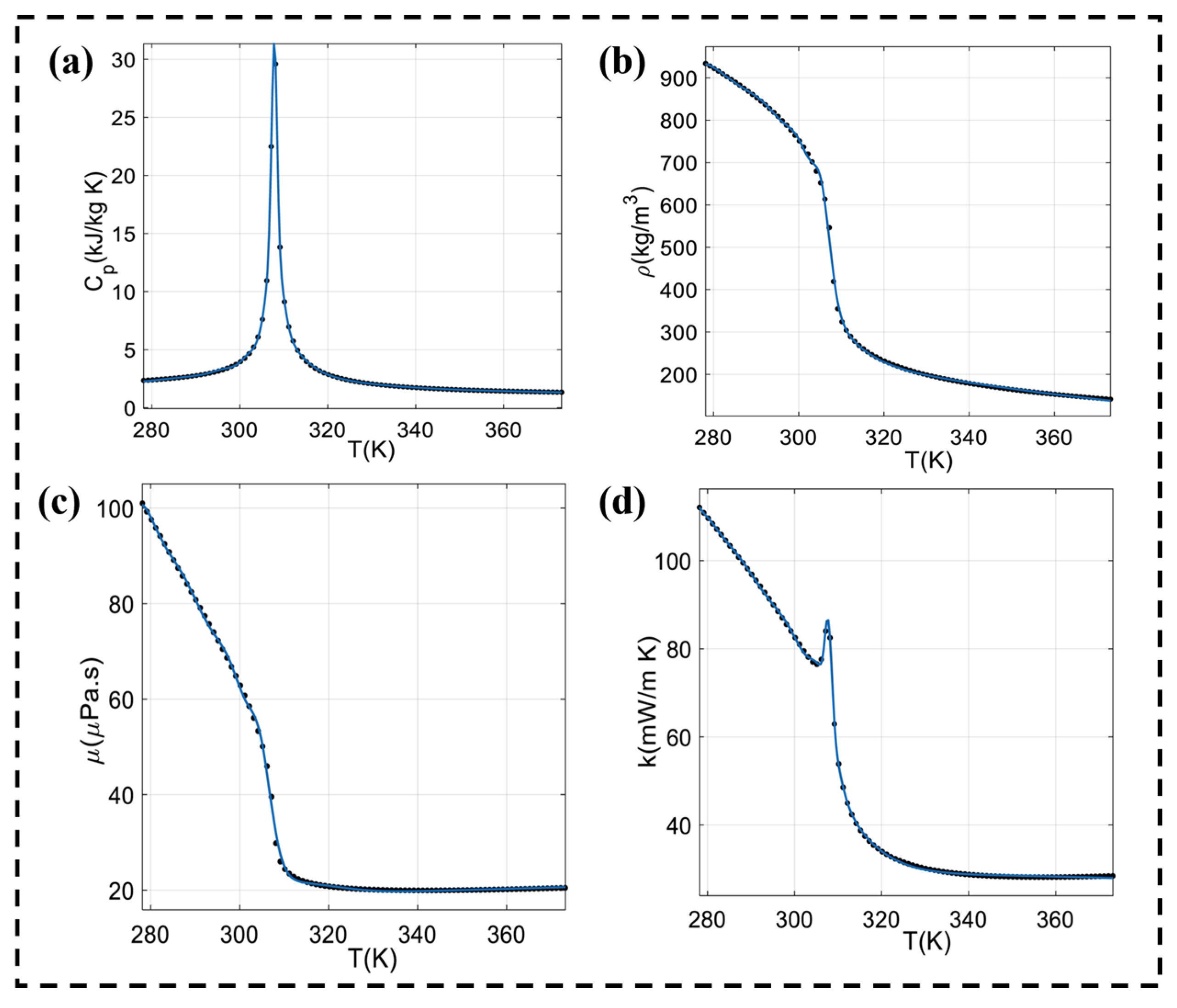
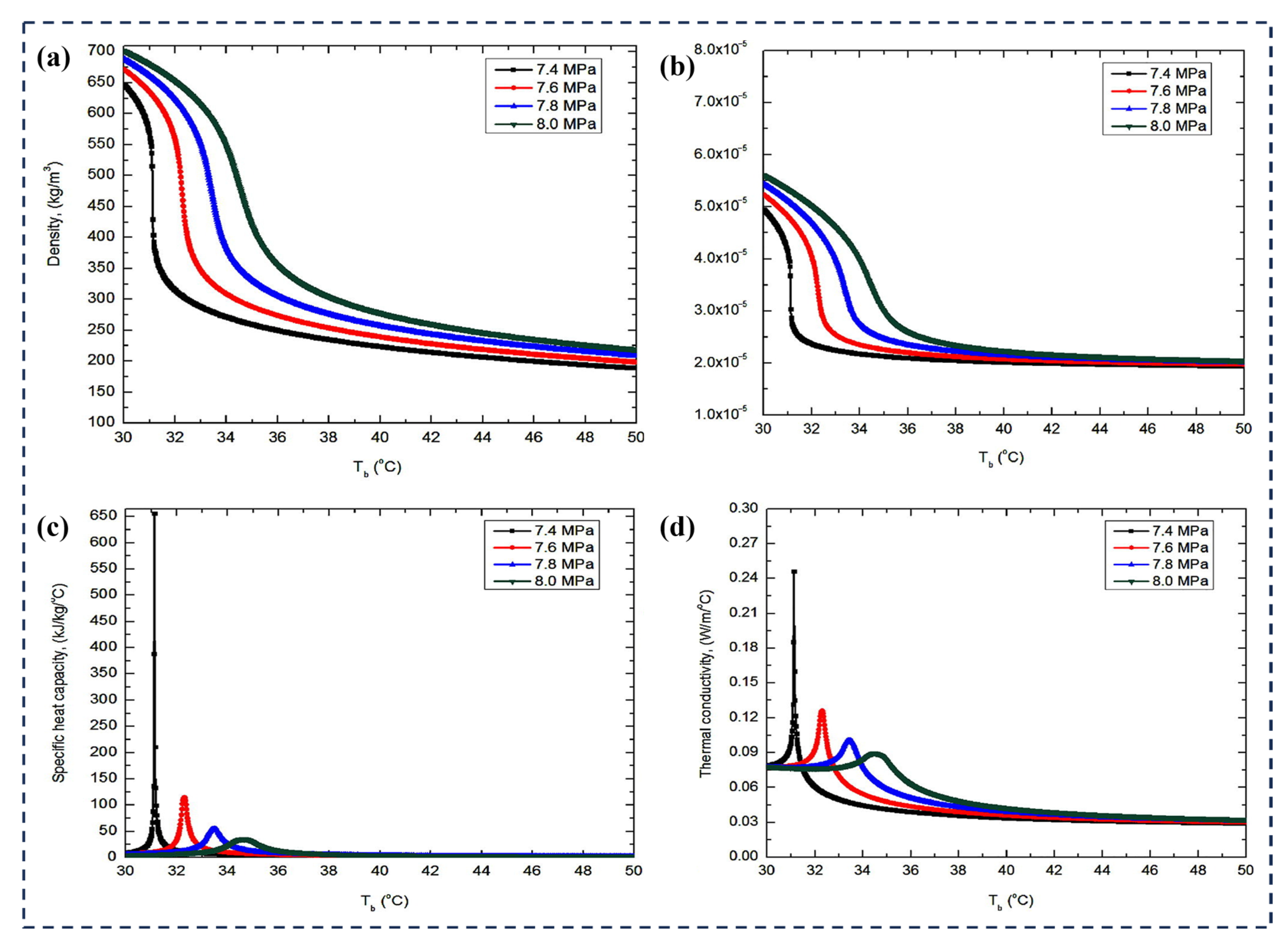
Near the critical or pseudocritical point, the thermophysical properties of SCO2, such as the density, specific heat capacity, thermal conductivity, viscosity, thermal expansion coefficient, and Prandtl number, change rapidly, enhancing forced convection heat transfer (Figure 2). Furthermore, SCO2 has excellent thermodynamic properties, including low viscosity [24], high density, good thermal conductivity, and relatively low parasitic energy consumption [25].
Near the critical or pseudocritical point, the rapid changes in the thermophysical properties of SCO2, such as the density, specific heat capacity, thermal conductivity, viscosity, thermal expansion coefficient, and Prandtl number, result in enhanced forced convection heat transfer.
As shown in Figure 2a, the density of SCO2 decreases as the temperature increases, with more rapid density changes occurring near the critical point. These characteristics, combined with low viscosity and favorable transport properties, render SCO2 advantageous for thermal–hydraulic applications [27]. As shown in Figure 2b,c, the viscosity and thermal conductivity show similar trends, both decreasing with increasing temperatures. Near the critical point, the viscosity decreases significantly, while the fluid velocity or Reynolds number increases markedly. The density reduction enhances buoyancy and fluid flow, while the thermal conductivity decreases. The thermal conductivity of SCO2 is a key thermophysical property influencing the mathematical models of chemical engineering design and practical systems in the natural gas industry [28]. As shown in Figure 2d, when the fluid temperature approaches the critical or pseudocritical temperature, the specific heat capacity increases significantly, enabling the fluid to absorb more heat at a given temperature. Across all pressure conditions, the specific heat of CO2 peaks near the critical temperature region. When the pressure is 7.5 MPa, the specific heat peak reaches its highest value. Conversely, the specific heat is lowest when the temperature exceeds the high-pressure condition. As the supercritical pressure increases, the peak of the specific heat capacity (Cp) value decreases significantly [29]. However, beyond the critical point, the heat transfer performance deteriorates [30]. In the 1960s, Hendricks et al. [31] discovered heat transfer deterioration (HTD) during convective heat transfer experiments with supercritical fluids [32].
Once the critical limit is reached, SCO2 pool boiling diminishes, evidenced by a significant drop in the peak heat transfer rate. Under supercritical conditions, heat transfer at low heat flux is limited to the natural convection regime. At elevated heat flux levels, the heat transfer characteristics and the near-wall flow field structure show similarities to those observed in subcritical film boiling [33]. Based on the research data on SCO2 and supercritical water (SH2O) published by Kim et al. [34] and Li et al. [35], the normalized dimensionless heat transfer coefficient of SCO2 is significantly higher than that of SH2O. This indicates that SCO2 has better heat transfer performance than SH2O.

3. Experiments on SCO2 Heat Transfer in Microchannels

Given SCO2’s excellent heat transfer properties and the high efficiency and compact structure of microchannels as a heat transfer medium [36], microscale convection heat transfer has become a widely studied topic [37].

3.1. Horizontal Microchannels

Recent studies on SCO2 heat transfer in horizontal microchannels are summarized in Table 1, covering heat transfer characteristics under varying tube diameters, pressures, and mass flow rates. Manda et al. [38] investigated a microchannel with an inner diameter of 100 µm and a total length of 27 mm, finding that a higher pressure and inlet temperature significantly enhance the heat transfer efficiency. Since different cross-sectional shapes have different surface areas, the surface heat flux density is not discussed. Yang et al. [39] studied the heat transfer performance of SCO2 in a horizontal pipe with a 10 mm inner diameter under non-uniform heating. They found that at low mass flow rates, the top heat transfer coefficient decreased significantly.
Wang et al. [40] and Yoon et al. [41] investigated the heat transfer characteristics of SCO2 in microchannels. Wang L et al. studied the effect of the inlet temperature and pressure on SCO2 heat transfer in microchannels with diameters of 0.5–1.0 mm, concluding that higher inlet temperatures weaken convective heat transfer. They extended the study parameters to cover different flow levels and found that the high-flow–high-temperature thermal resistance was close to the critical point. Chen et al. [42] investigated how the pipe diameter affects the flow resistance and heat transfer in microchannels with an inner diameter of 8–12 mm. They showed that the heat transfer coefficient decreased as the pipe diameter increased, particularly at low flow rates. Yan et al. [43] investigated an 8 mm inner diameter × 3080 mm long tube for SCO2–xenon mixture cooling heat transfer. They found that adding a small amount of xenon gas enhances the cooling effect but reduces the heat transfer coefficient. Manda et al. [44] analyzed the heat transfer performance of SCO2 in a horizontal microchannel with an inner diameter of 0.69 mm and a total length of 14.08 mm. They demonstrated that a large mass flow combined with a small pipe diameter can significantly enhance the heat transfer coefficient. The study also highlighted the substantial impact of the geometric structure on the heat transfer efficiency.
There is broad agreement that an elevated pressure and inlet temperature can significantly enhance SCO2 heat transfer efficiency in microchannels. The microchannel dimensions (e.g., diameter and length) and flow conditions also play a crucial role in determining the heat transfer performance. Scholars generally agree that higher pressures and inlet temperatures can significantly boost the efficiency of SCO2 heat transfer in microchannels. But there is still debate over some issues. For example, some think that a higher inlet temperature might weaken the heat transfer efficiency. Also, the specific impact of pipe diameter changes on the heat transfer coefficient is not fully clear. And the effect of adding gases like xenon on heat transfer performance remains uncertain. These topics need more research.

3.1.1. Section Size and Structure

The cross-sectional shape or geometry of microchannels has a significant impact on the heat transfer and flow characteristics of the cooling medium. Different geometric configurations lead to different heat transfer coefficients, mass flow rates, and pressure drop characteristics, which play an important role in the efficiency of microchannel radiators. To illustrate the key geometric features studied in this research, Figure 3 provides a schematic diagram of the microchannel test cross-section. In this schematic diagram, the area occupied by the cooling fluid flow and the surrounding solid structure are shown. Crucially, the interface between the solid structure and the fluid domain represents the heated surface through which thermal energy is transferred to the fluid domain. Figure 3 particularly emphasizes the variations in the geometric profiles of the fluid channels themselves (such as rectangles, circles, triangles, and semi-circles), as the shape of this boundary fundamentally affects the final thermal performance, as discussed above.
In this work, the term “microchannel” refers to channels with hydraulic diameters typically ranging from about 0.1–10 mm, including common geometric shapes such as rectangular and circular pipes. They are usually fabricated using specialized techniques such as etching or precision microfabrication and are mainly used for experimental research on the flow of SCO2. For comparison, river channels with a hydraulic diameter of about 10 mm or more are usually classified as conventional river channels or macroscopic river channels [36]. The microchannel’s cross-sectional geometry significantly affects the cooling medium’s thermal transfer and flow properties, thereby greatly influencing the microchannel radiator’s efficiency. It should be noted that these effects are observed under specific experimental conditions and interact with other critical factors, including the hydraulic diameter, surface-to-volume ratio, flow regime, surface roughness, and thermal boundary conditions. Derby et al. [45] conducted a study on the condensing heat transfer parameters in microchannels with varying cross-sectional shapes using R134a coolant at a hydraulic diameter of 1 mm, concluding that the channel’s cross-sectional geometry has a minimal effect under their specific test conditions. Manda et al. [38] modeled four microchannel shapes under controlled zero-gravity and constant-ground-temperature conditions, finding that triangular sections provided the highest heat transfer rate and lowest pressure drop, while circular sections yielded the highest average heat transfer coefficient but largest pressure drop. Wang et al. [46] observed that the square channel’s top surface forms the thinnest liquid film, thereby enhancing the areal mean heat transfer coefficient. Under both zero-gravity and ground conditions, circular-section microchannels exhibit the largest pressure drop and the highest average heat transfer coefficient [38]. These studies indicate that the influence of the channel shape is restricted by environmental conditions. Under the same restrictive conditions, microchannels with different cross-sectional shapes have their own advantages in terms of heat transfer and flow performance. In scenarios with minimal pressure drop requirements, triangular or square sections are more suitable for applications, because they exhibit lower pressure losses. In cases where the heat transfer rate needs to be maximized, a circular cross-section is advantageous. We can combine the advantages and disadvantages of each section to optimize the microchannel design for different application requirements, thus maximizing the heat transfer efficiency.

3.1.2. Pressure Drop

Near the pseudocritical point, significant changes occur in the properties and transport phenomena of supercritical carbon dioxide along the flow path, influencing the pressure drop of SCO2 through the channel. Analyzing the pressure drop characteristics of SCO2 is vital for ensuring the safe operation of supercritical systems and for designing carbon dioxide coolers in crosscritical cycles. Liu et al. [47], Son et al. [48], and Yun et al. [49] conducted studies on the pressure drop of supercritical carbon dioxide during heat transfer.
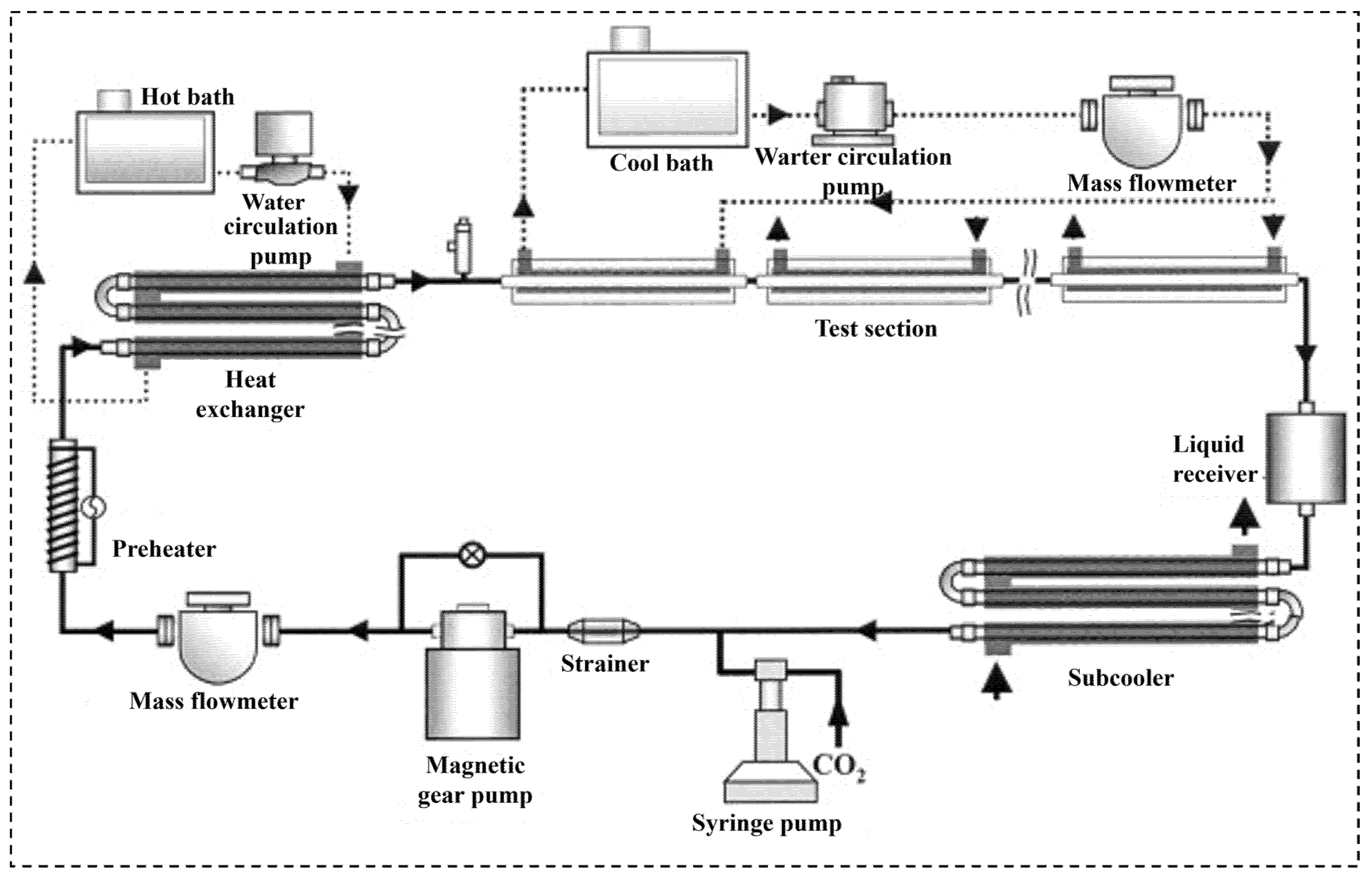
Yoon et al.’s [41] research measured the heat transfer coefficient and pressure drop during carbon dioxide gas cooling, with the experimental setup being shown in Figure 4. The measured pressure drop in the test section is consistently at below 1 kPa·m−1 across all test runs, increasing with a higher mass flux and decreasing system pressure.
The total pressure loss markedly escalates with an increase in mass flow rate and intake temperature; however, it diminishes considerably with elevated outlet pressure and a greater pipe diameter. Moreover, in turbulent supercritical flow within the tube, the significant reduction in fluid density results in an expedited pressure drop. The impact of pressure drop acceleration becomes more pronounced with increasing tube diameters [50].
The frictional pressure drop of the fully developed turbulent single-phase flow in the smooth tube is shown in Equation (1). The research verifies the accuracy by comparing the measured values with the calculated values.
Δ P = f G 2 L 2 ρ D i
where
Δ P is the frictional pressure drop (Pa);
f is the Darcy friction factor;
G is the mass flux (kg m−2 s−1);
L is the pipe length (m);
ρ is the fluid density (kg m−3);
D i is the inner tube diameter (m).
The Darcy friction factor f for the turbulent flow is calculated using Equations (2) and (3).
f = 0.316 R e 1 / 4   f o r   R e 2 × 1 0 4
f = 0.184 R e 1 / 5   f o r   R e 2 × 1 0 4
Here, R e = G D i μ is the Reynolds number based on the inner tube diameter, and μ is the dynamic viscosity of the fluid.
Wang’s research concentrated on small-diameter pipes and revealed that temperature variations at the pseudocritical point significantly influenced the heat transfer coefficient, whereas elevated mass flow rates and reduced pipe diameters enhanced the heat transfer efficiency. Yoon’s research examines larger-diameter (7.73 mm) copper tubes, measuring the pressure drop during the gas cooling process, and introduces new empirical formulas to enhance the prediction of the heat transfer coefficient and pressure drop in the near-critical area.

3.1.3. Heat Transfer

In the study of SCO2 microchannel heat transfer, various operating conditions and geometric shapes have significant effects on the heat transfer characteristics. The study conducted by Manda et al. [38] demonstrated that under terrestrial conditions (1 g), increasing the mass flow rate and heat flux significantly enhances the heat transfer coefficients of microchannels with varying geometric cross-sections, particularly near the pseudocritical point. At this time, the rapid changes in temperature and pressure cause the heat transfer coefficient to fluctuate significantly, resulting in a significant thermal enhancement effect. When the operating temperature is far from the pseudocritical point, the heat transfer rate decreases as pressure increases, because physical property changes become less responsive. When the operating surface temperature exceeds 330 K, high pressure significantly enhances the heat transfer coefficient, highlighting the importance of the synergistic high-temperature and high-pressure effect for heat transfer improvement [51].
The flow heat transfer characteristics of SCO2 in microchannels with limited heating lengths were analyzed by the numerical simulation undertaken by Manda et al. [44]. The results show that the convective heat transfer coefficient in the microchannel decreases significantly under the condition of accelerated flow. This phenomenon can be attributed to the high acceleration destroying the turbulent structure, resulting in a weakening of the mixing and heat transfer capacity of the fluid. This indicates the need to strike a balance between velocity and flow characteristics in microchannel design to avoid excessive accelerated flow adversely affecting the heat transfer performance.
The experimental and simulation results show that the heat transfer near the pseudocritical region is most significant, so this operating condition should be prioritized. Reducing the hydraulic diameter of the microchannel can boost the heat transfer performance, while optimizing the geometric cross-section effectively enhances the heat transfer performance. Excessive velocity acceleration may destroy the turbulent structure and reduce the heat transfer efficiency, so it is necessary to control the flow parameters effectively.
The heat transfer performance of SCO2 in microchannels is related to the cross-section design, pressure, flow velocity, and buoyancy effect of the microchannel. When future studies need to enhance the heat transfer of SCO2 in microchannels, microchannels with triangular sections can be selected to work under higher pressure (when the surface temperature is higher than 330 K), and the heat transfer flow speed can be increased to improve the heat transfer coefficient.

3.2. Vertical Microchannels

Vertical microchannels have unique heat transfer characteristics compared to horizontal ones, making it essential to conduct dedicated studies on vertical microchannels. The primary differences lie in the effects of buoyancy and flow direction (upward or downward), as well as the interaction between these factors and the heat transfer performance. These differences highlight the importance of investigating vertical microchannels to better understand and optimize their design and operation. The focus is on the differences between vertical and horizontal microchannels, as well as how experimental factors like inlet diameter, mass flux, inlet pressure, and heat flux impact the heat transfer performance of vertical microchannels.
Table 2 summarizes the parameters of experiments related to vertical microchannels, including the inner pipe diameter, mass flow rate, inlet pressure, and heat flux, and reveals the differences in experimental designs and the changing trend of heat transfer performance. Wang et al. [15] studied the local convective heat transfer properties in a vertically and uniformly heated microtube. During downward vertical flow, the buoyancy effect enhances local heat transfer, while during upward vertical flow, it has a negative impact. As the system approaches the pseudocritical point, horizontal flow exhibits the best heat transfer performance. Conversely, when the outlet fluid temperature is well above the pseudocritical point, vertical downward flow shows better heat transfer performance [40].
When investigating heat transfer performance, Wang et al. [55] studied the flow and heat transfer instability of supercritical carbon dioxide in a vertical heating tube and proposed a numerical analysis method based on a transient model. It was shown that when the wall heat flux exceeds the critical value, the density and mass flow of SCO2 change sufficiently to cause the self-sustained oscillation of the flow, which leads to heat transfer instability.
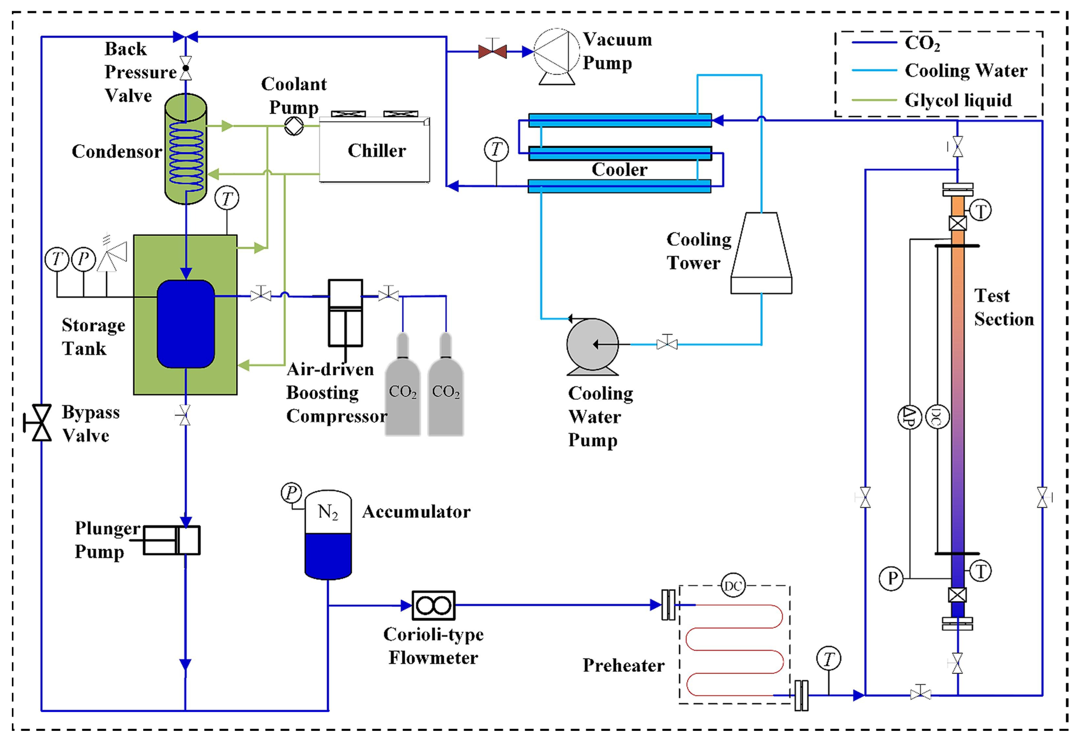
The experiments shown in Figure 5 investigated the convective heat transfer characteristics of SCO2 when flowing up and down a vertical tube with a diameter of 10 mm and a mass flux of 100 to 350 kg/(m2·s) [52].
It is concluded that an increase in mass flux is beneficial for heat transfer, while an increase in pressure alone is not beneficial. Under the same conditions, downward flow demonstrates superior heat transfer efficiency relative to upward flow.

3.2.1. Heat Flux Effects

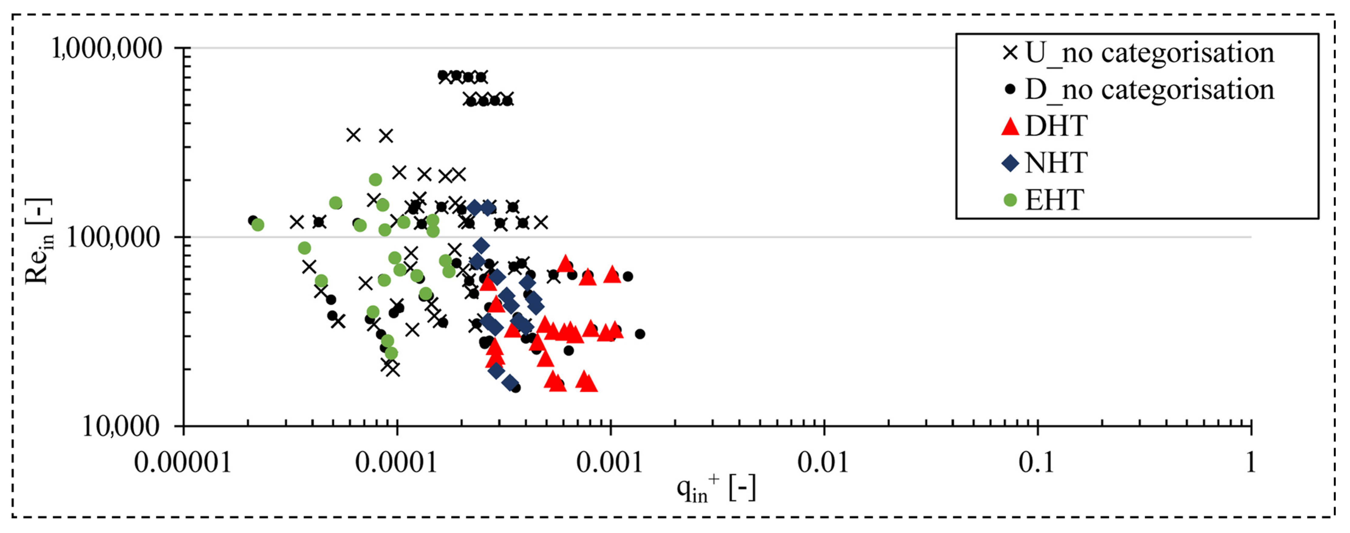
The heat flux has a significant influence on the thermal performance of vertical microchannels in SCO2 flows. As the heat flux increases, the wall temperature sharply increases, particularly near the pseudocritical point, where variations in thermophysical properties are most pronounced. In their experimental analysis, Theologou et al. [56] found that HTD is caused or enhanced by the heat inflow effect under certain circumstances, and that heat transfer is enhanced by the heat inflow effect at high Reynolds numbers, as shown in Figure 6.
At moderate heat flux, a single temperature peak is often observed, indicating localized HTD. When the heat flux becomes higher, multiple peaks may form due to intensified buoyancy effects and flow instability. The experimental results highlight that increasing the heat flux exacerbates HTD and shifts the temperature peaks upstream, indicating the need for optimized thermal control in high-flux applications.

3.2.2. Buoyancy Role

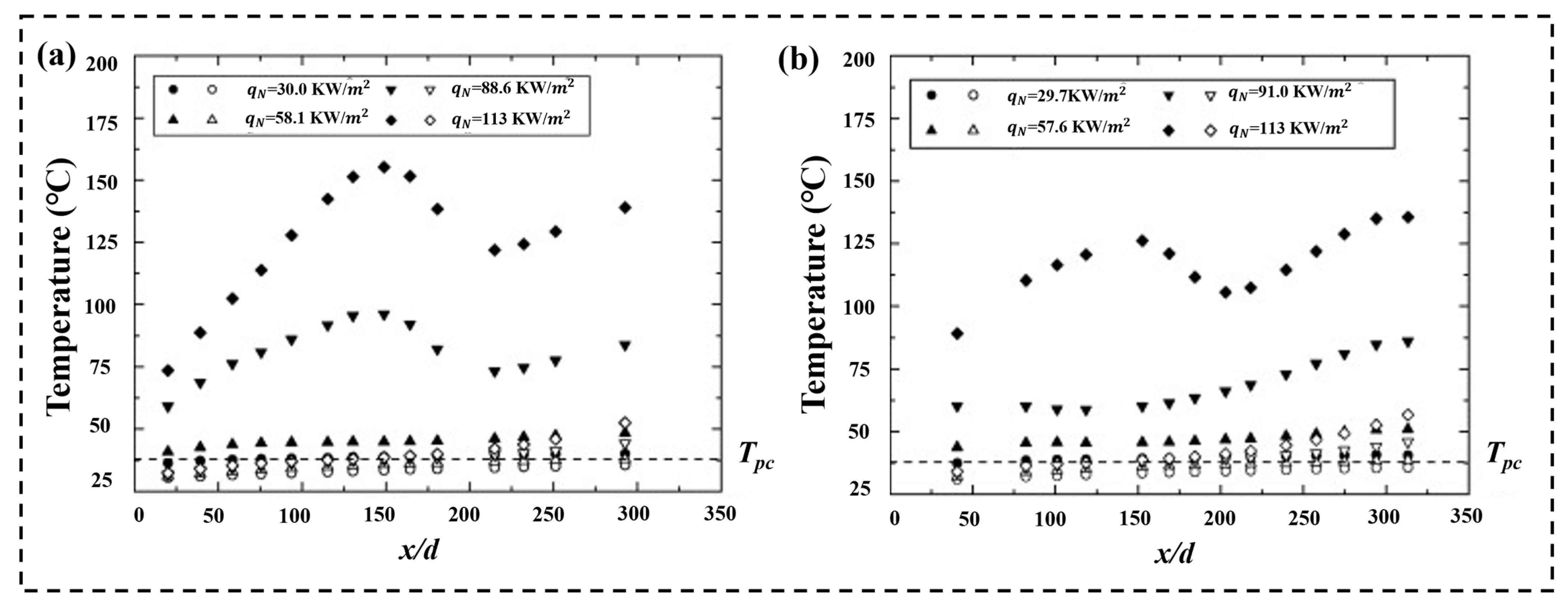
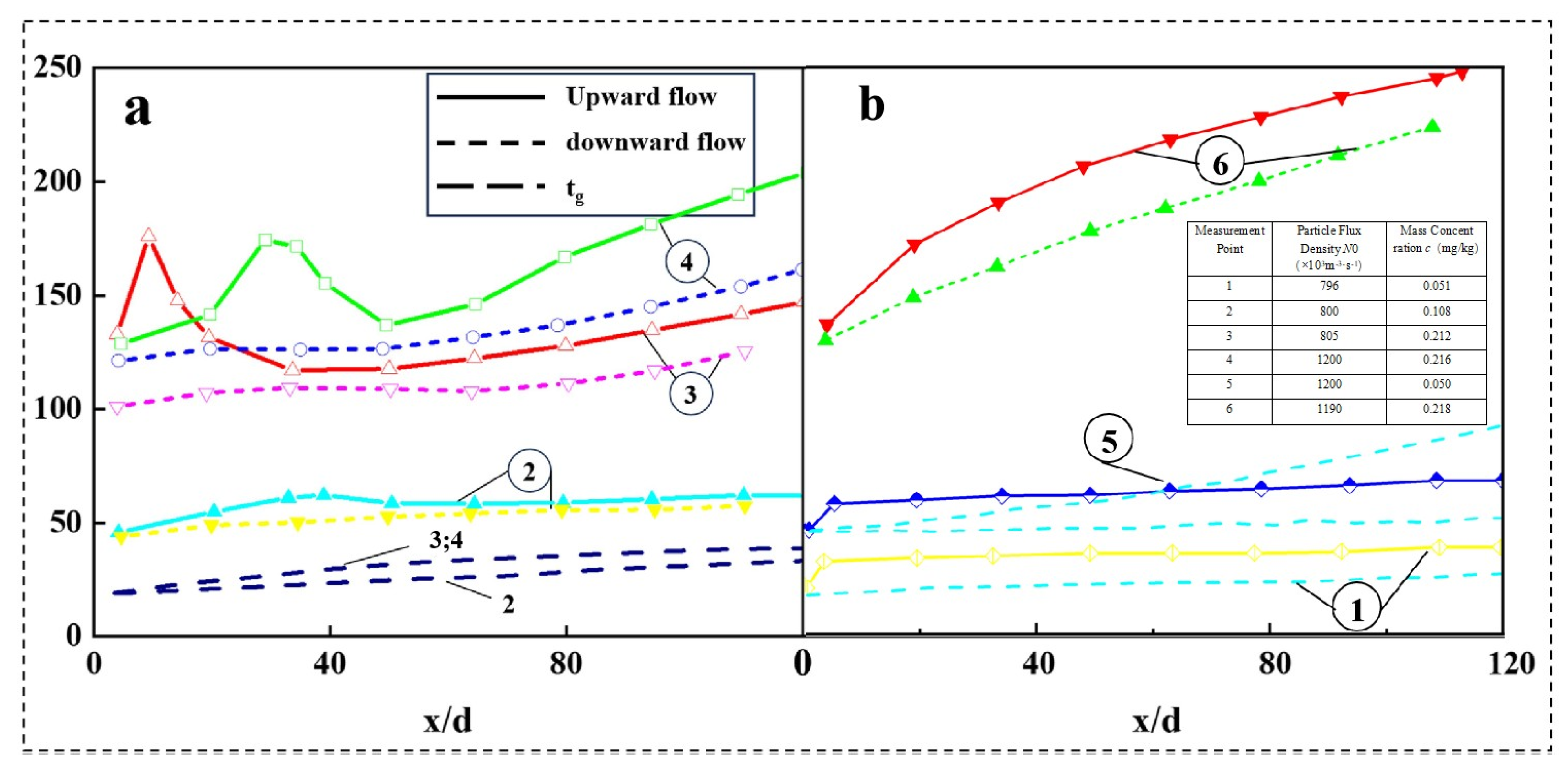
Buoyancy effects in vertical microchannels arise from the density gradient that is caused by wall heating, leading to variations in flow structure and turbulence intensity. Jiang et al. [53] studied the upward and downward flow of SCO2 in a 0.27 mm diameter vertical microtube at low Reynolds numbers. Figure 7 shows that when the heat is very high, the temperature of the wall changes in a nonlinear way for both flow directions, and the effect of buoyancy is usually small during intense heating.
According to a convective heat transfer experiment by Jiang et al. [57], in a 2.00 mm vertical microtube with a small inner diameter and upward flow, the buoyancy of SCO2 generally reduces the turbulence near the wall, resulting in impaired heat transfer and increased wall temperatures. In contrast, downward flows experience enhanced turbulence due to buoyancy, improving the thermal performance and minimizing HTD. The direction and magnitude of buoyancy effects are closely tied to the flow rate, heat flux, and pressure conditions. Accurate prediction and management of buoyancy effects are critical for ensuring stable thermal performance in vertical systems.
In addition, pressure variations play a crucial role in determining the heat transfer characteristics of SCO2. Higher pressures elevate the pseudocritical temperature, reducing the extent of thermophysical property variations and mitigating HTD. At lower pressures, where the fluid temperature is closer to the pseudocritical point, more pronounced property fluctuations lead to stronger buoyancy effects and a higher likelihood of HTD. Experimental data demonstrate that increasing the pressure smoothens the wall temperature profile and delays the onset of HTD, making pressure control an effective strategy for optimizing vertical microchannel heat transfer performance [29].

4. SCO2 Heat Transfer Efficiency in Microchannels

Improving the heat transfer efficiency of SCO2 in microchannels is critical for enhancing the performance and reliability of compact heat exchange systems. The unique thermal properties of SCO2, especially near its critical point, provide opportunities for achieving a high heat transfer efficiency but also pose significant challenges due to complex fluid dynamics and thermophysical behavior [58]. This section focuses on the evaluation methods, influencing factors, and optimization strategies for heat transfer efficiency in microchannels, providing a comprehensive framework to understand and improve the thermal performance of SCO2-based systems.

4.1. Heat Transfer Efficiency Evaluation Methods

The commonly used evaluation methods for heat transfer efficiency include the Nusselt number ( N u ) method, total heat transfer coefficient (U) method, and pressure drop ( Δ P ) analysis method.
The Nusselt number is defined as shown in Equation (4):
N u = h D h k
where
h is the convective heat transfer coefficient (W m−2 K−1);
D h is the hydraulic diameter (m);
k is the thermal conductivity of the fluid (W m−1 K−1).
The overall heat transfer coefficient is defined as shown in Equation (5):
U = Q A Δ T m  
where
Q is the heat transfer rate (W);
A is the heat transfer area (m2);
Δ T m is the log-mean temperature difference (K).
The pressure drop for flow inside ducts is defined as shown in Equation (6):
Δ P = f L D h ρ v 2 2
where
f is the Darcy friction factor [defined in Section 3.1.2, Equations (2) and (3)];
L is the length of the duct (m);
ρ is the fluid density (kg m−3);
v is the average fluid velocity (m s−1).
The higher the N u is, the stronger the fluid’s convective heat transfer capacity becomes. Near the vicinity of the pseudocritical point, the thermal properties of SCO2 change dramatically, and N u usually increases significantly, reflecting the heightened heat transfer capabilities of the fluid. The higher the U is, the better the heat transfer between the fluid and the wall is, while a lower Δ P generally means less energy loss in the system.
A larger Nusselt number and a higher total heat transfer coefficient suggest a more robust heat transfer. Smaller pressure drop losses are usually associated with a lower system energy consumption, reflecting a higher heat transfer efficiency.
Additionally, methods such as the thermal resistance model approach and the combination of experimental and numerical simulation methods are often used to evaluate heat transfer efficiency. A low thermal resistance is helpful to improve the heat transfer efficiency. The admixture of experiments and numerical simulation verifies the simulation results through microscale experimental data and evaluates the heat transfer efficiency, providing a reliable assessment methodology for heat exchanger design. These two methods have their own advantages and can be used in combination with each other in different research stages and working conditions to comprehensively improve the evaluation accuracy of SCO2 microchannel heat transfer efficiency.

4.2. Key Factors Affecting the Heat Transfer Efficiency of SCO2

In the heat transfer process of SCO2, the drastic change in physical properties near the critical point has an important effect on the heat transfer efficiency. As the temperature of SCO2 increases and the pressure decreases, its density decreases substantially, resulting in a significant expansion of the fluid volume. This expansion effect will cause the flow rate to increase, forming a flow acceleration phenomenon [59]. This action greatly suppresses turbulent kinetic energy, particularly in proximity to the wall. Reducing turbulence right away changes how mixing happens near the wall, which boosts the wall’s thermal resistance and reduces the heat transfer efficiency. The boost in flow effect is congruent with the flow direction, leading to diminished heat transfer and efficiency, hence impacting the thermal performance of the MCHS.
The literature also suggests that the specific heat capacity of SCO2 near its pseudocritical point reaches a peak, significantly boosting the fluid’s heat storage capacity. However, the impact of the heat capacity is constrained by the diminution in the fluid’s thermal conductivity and the suppression of turbulent kinetic energy due to flow acceleration, which puts a hard limit on how much better the system can transfer heat overall. Especially in microchannels, the combination of high-speed flow and a low wall temperature difference tends to form so-called “heat transfer degradation zones”, which further restricts the system’s ability to dissipate heat.

4.3. Heat Transfer Efficiency Optimization Strategies

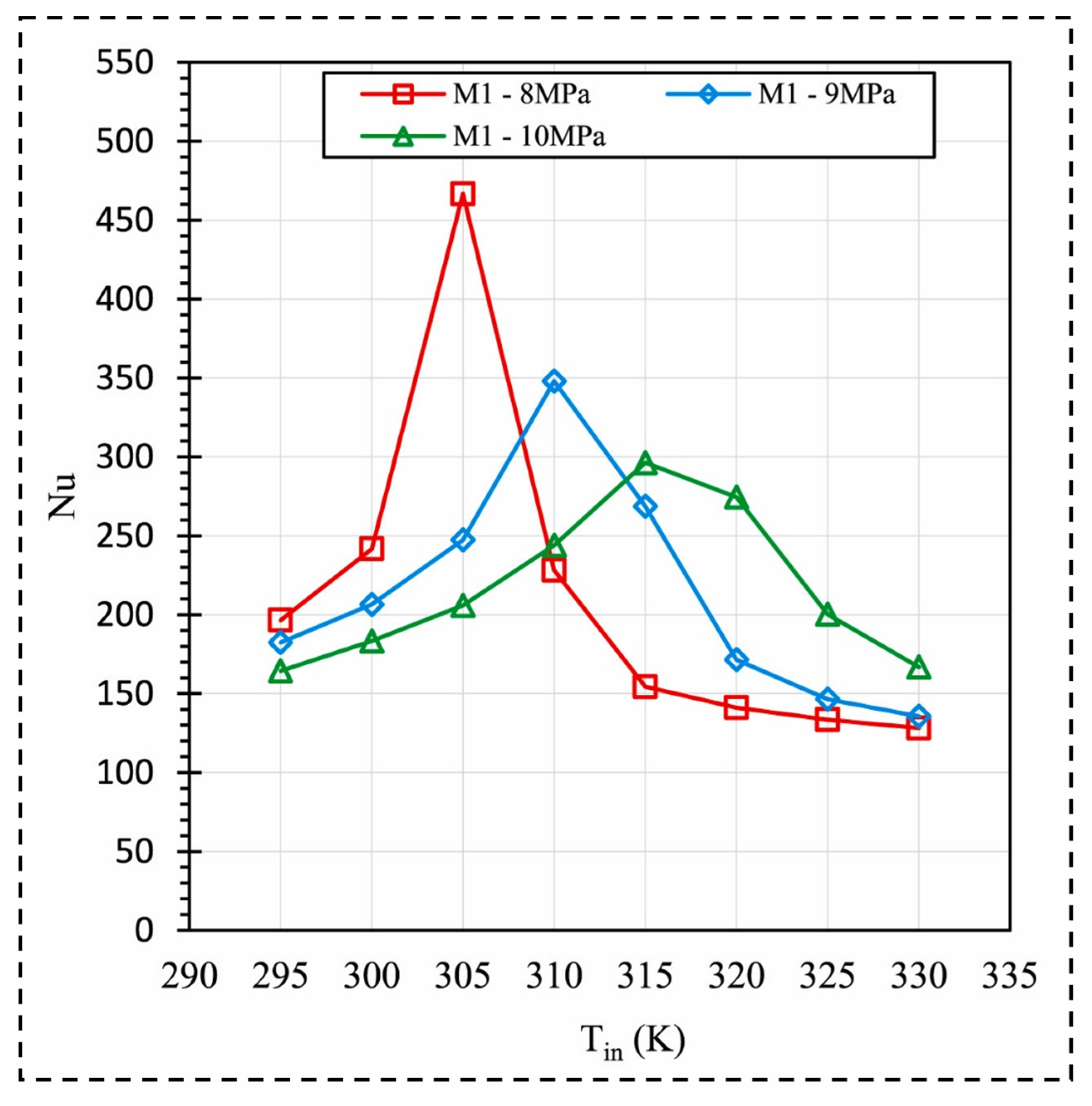
Chen et al. [60] conducted a detailed thermodynamic analysis of the system combined with the supercritical carbon dioxide Rankine cycle and the absorption refrigeration cycle and found that reasonable adjustments of the mass flow ratio and evaporation temperature could significantly optimize the thermodynamic performance of the system. The uniquely low viscosity of SCO2 promotes turbulent flow in microchannels and improves the heat transfer efficiency [61]. Hung et al. [62] explored regulating the Reynolds number by changing the inlet flow rate and found that increasing the Reynolds number would lead to an increase in the Nu number of all models under different geometries, thus improving the heat transfer efficiency. In addition, they also observed that the best heat transfer (peak efficiency) happens near a key temperature point when operating at 8 MPa pressure (Figure 8) [63].
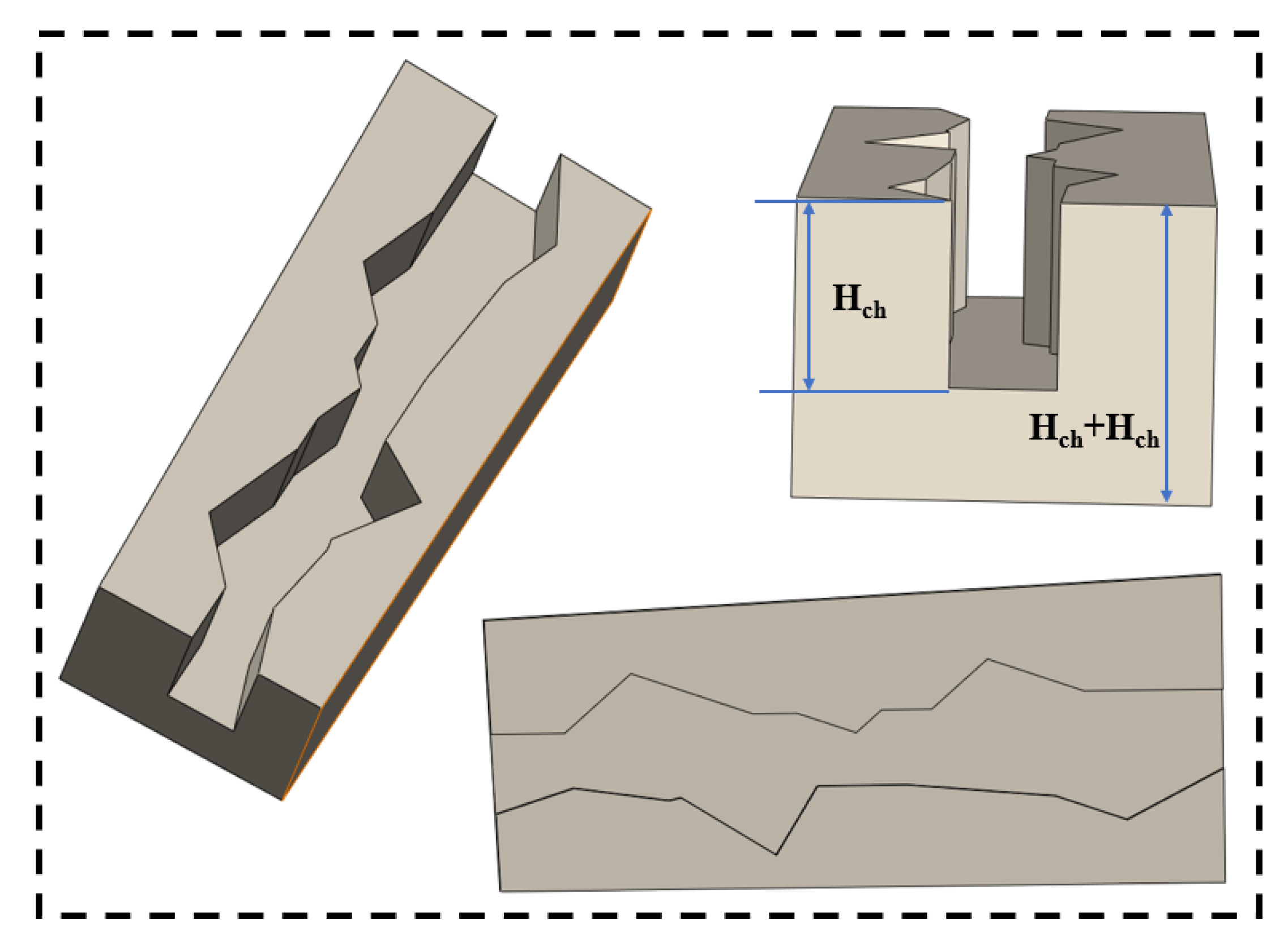
Researchers have found that microchannels with complex tiny structures can increase the area where a fluid meets solid surfaces, breaking up the flow layer to improve heat transfer; as a result, many different channel designs have been created to boost the heat transfer efficiency [64]. For example, Zhai et al. [65] used the MCHS geometric model, which incorporates cavities and fins, as shown in Figure 9, to effectively disrupt the boundary layer, thereby enhancing the heat transfer efficiency of the microchannel. However, the MCHS has limitations in heat transfer, and it was further found that porous media can be integrated into an MCHS to increase the heat transfer capacity of coolants in contact with solids [66]. Yang et al. [67] analyzed turbulent forced convection heat transfer in rectangular ducts and found that the pipe with a porous baffle has a lower friction coefficient and higher heat transfer efficiency.
The researchers also found that vortex generators can optimize the heat transfer efficiency. The growth of the heat transfer surface, vortex formation, and secondary flow enhancement can increase heat transfer [68]. For example, in the channel that generates transverse vorticity studied by Valencia et al. [69], the heat transfer coefficient increased by 1.78 times. Further, Moosavi et al. [70] found that microchannel porous media can be combined with transverse vortex generators (TVGs), and the heat transfer coefficient increases by 12 times when the porous media is filled, while the heat transfer coefficient of eight vortex generators and TVGs occupying 12.5% of the channel height increases by 2.6 times, effectively improving the heat transfer efficiency. The new cooling wall tube design created by Wang et al. [71] can significantly lower the highest temperature and temperature differences by matching uneven heat flow with the wall’s thermal resistance, which improves the heat transfer efficiency.

5. Heat Transfer Deterioration (HTD) in Microchannels

Microchannels find extensive use in microelectronics cooling, micro-heat exchangers, and various other domains due to their effective heat transmission properties. However, in these microscale structures, heat transfer deterioration (HTD) could make the system work significantly less efficiently. Understanding the cause of HTD and its impact on microchannel performance is critical to optimizing designs and improving system reliability.

5.1. Mechanisms of HTD in Microchannels

The occurrence of HTD is closely related to the unique thermophysical properties of supercritical fluids in microchannels. These properties change rapidly under specific high-pressure, high-temperature conditions (Figure 10). These changes induce strong buoyancy and thermal acceleration effects, especially in microchannels, whose small hydraulic diameter accentuates these phenomena. The onset of HTD is often associated with these effects, and they show up as sudden temperature spikes in the pipe wall, along with a big drop in the heat transfer efficiency (HTC). Buoyancy effects, driven by density variations in the fluid as it heats, play a crucial role in HTD, particularly in vertical microchannels. Additionally, thermal acceleration, resulting from rapid fluid expansion due to heating, significantly contributes to HTD, complicating the heat transfer process further [72].
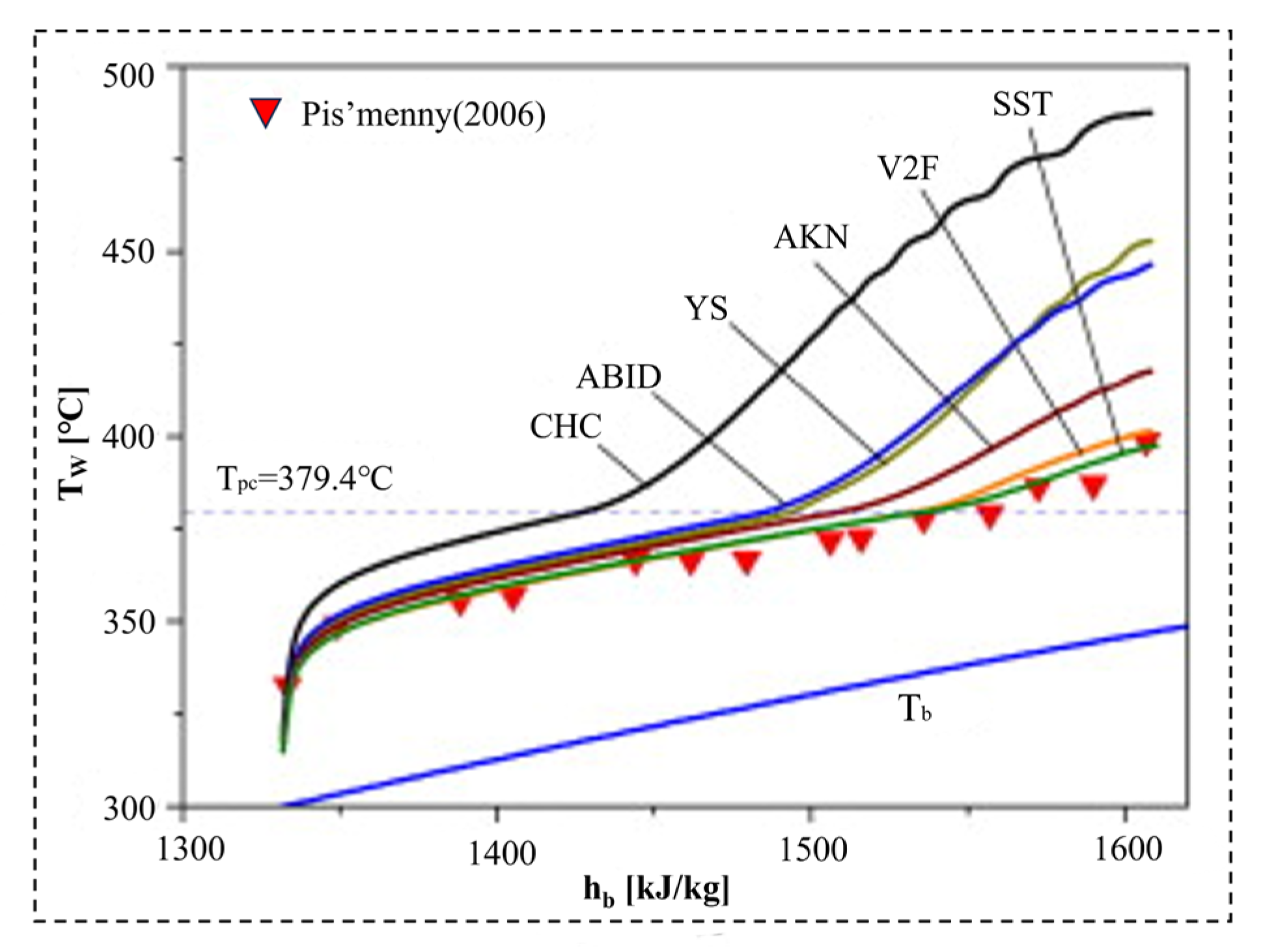
He et al. [73] used an internal CFD code grounded in the Favre average method to perform computational simulations of fluid heat transfer under supercritical pressures. They determined that the damping functions of the turbulence model for low Reynolds numbers, which rely on variables that are highly sensitive to buoyancy and flow acceleration, considerably overestimate flow laminarization, leading to reduced heat transfer efficiency. As shown in Figure 11, Wen et al. [74] also used a low Reynolds number model to simulate the buoyancy effect on HTD, yet all of them seriously overestimated HTD, and only the V2F (Behnia–Parneix–Durbin) model and SST (Menter) models had better ability to predict the degradation.

5.2. Factors Influencing HTD

Buoyancy and acceleration effects are recognized as factors causing large changes in thermophysical properties, but whether they can improve or worsen heat transfer remains unclear. Furthermore, several experts have suggested the pseudo-boiling theory. Kurganov et al. [81] posited that in bigger pipes, buoyancy forces mainly control how heat moves and fluids flow, whereas flow acceleration was the primary influence in small-diameter tubes. The heat transfer forms considered in Kurganov’s study are shown in Figure 12, where there are “inlet * wall temperature peaks” with different strengths (Figure 12a) and areas with monotonous heat transfer distribution along the tube length direction (Figure 12b). Certain differences in heat transfer between upward and downward flow indicate that buoyancy is the main influencing factor [82].
Song et al. [83], Zahlan et al. [84], Zhao et al. [85], and Oh et al. [86] determined the heat transfer performance of SCO2 in the vertical flow of pipes with different pipe diameters and found that buoyancy has a smaller impact in narrower pipes; that is, the larger the pipe diameter is, the more likely HTD is. Zhang et al. [32] studied heat transfer in supercritical CO2 flowing through a 10 mm vertical tube at different heating levels (37.75 to 782.48 kW/m2). Their observations revealed that buoyancy forces mainly caused weakened heat transfer near the tube entrance. They found that as the heat flow increases, the heat transfer of SCO2 in the inlet section decreases, and the heat-driven acceleration contributes to additional heat transfer weakening.
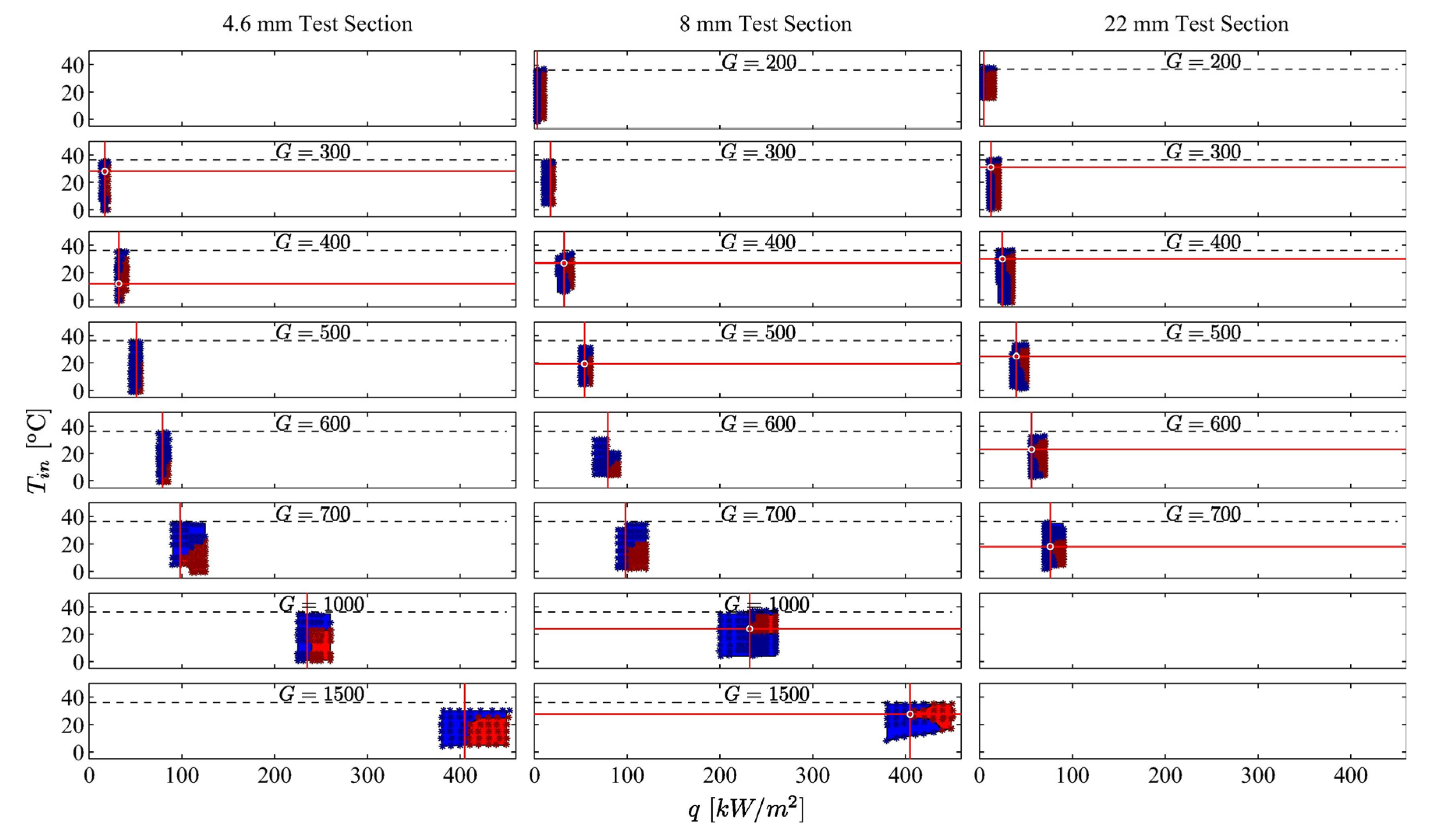
Kline et al. [87] reported that the occurrence of heat transfer deterioration (HTD) mainly depends on the inlet temperature ( T i n , °C) and the ratio of heat flux ( q , kW m−2) to mass flux ( G , kg m−2 s−1). As shown in Figure 13, HTD is completely non-existent when the q is lower than the minimum initial threshold. When working above this threshold, HTD occurs only when T i n is within the specific experimentally determined range and q / G exceeds the critical value. Crucially, HTD is manifested in the discrete and confined regions of the q and T i n parameter spaces, surrounded by the normal heat transfer (NHT) regions. This restriction means that the same q / G value can lead to HTD or NHT, depending entirely on whether T i n falls within or outside its critical window. Therefore, relying solely on the prediction models of G or q / G is insufficient.
Bae et al.’s [88] heat transfer experiments under different pressures show that the level and range of HTD hardly change. Rao et al. [29] concluded that temperature variations have a negligible effect on heat transfer during cooling but a profound effect during heating.
Key factors influencing HTD encompass buoyancy effects, flow acceleration, the q / G ratio, pipe diameter, pressure conditions, and temperature variations. Among them, the buoyancy effect is considered to have a greater impact in large-diameter pipes and is the primary reason for the significant difference in heat transfer between upward and downward flows. Meanwhile, flow acceleration is the key factor worsening heat transfer in small-diameter pipes. Furthermore, a larger q / G value will exacerbate local HTD, and the greater the pipe diameter is, the more significant the buoyancy effect is and the higher the likelihood of HTD occurring is. Although the range and intensity of HTD exhibit minimal variation under different pressure conditions, temperature changes substantially affect heat transfer behavior during heating. Research has identified buoyancy effects and flow acceleration as the primary influencing factors. Notably, buoyancy effects are particularly significant in scenarios involving large-diameter pipes and high-heat-flux conditions. Additionally, the enhanced impact of a larger q / G value on localized HTD is also considerable and should not be overlooked.

5.3. Mitigation Strategies

The numerical simulation of pipelines is critical to understanding and predicting HTD, enabling more effective design and operational strategies. Researchers have explored various strategies to mitigate the high-temperature deformation of microchannels, including the use of guide blades and baffles and changing the mass flux and tube diameter.
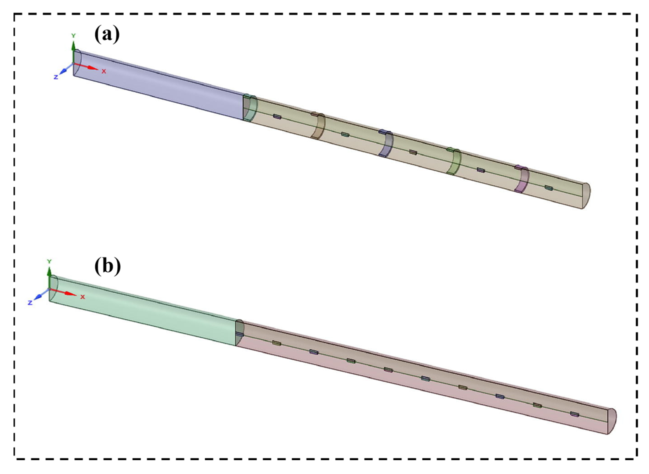
Luo et al. [89] improved the flow separation phenomenon through the design of the guide blade, thereby increasing the heat transfer efficiency. Wang et al. [71] verified the slowing effect of the baffle on HTD through experiments. As shown in Figure 14a, compared with other arrangements, the staggered baffles can enhance the fluid mixing in the pipe wall and core regions by triggering strong fluid oscillations, thereby more effectively suppressing the pipe wall temperature. However, the cost of this approach is significantly higher pressure loss. As shown in Figure 14b, the central baffle induced a jet to directly impact the baffle, which generated a large amount of lateral fluid velocity near the pipe wall, while the pressure loss was minimal, which had the greatest impact on HTD mitigation.
Numerous experimental studies have shown that supercritical heat transfer improves as the mass flux increases. From Figure 15, we can see the comparison of wall temperature under the conditions of low mass flux and high mass flux. With the appearance of the peak wall temperature, the difference between them is only about 10 °C under the condition of low mass flux in Figure 15a, while the difference reaches 55 °C under the condition of high mass flux in Figure 15b; that is, the high-temperature thermal resistance under high mass flux is often accompanied by a large heat transfer recovery process [90].
He et al. [91] applied a low-Reynolds-number eddy viscosity turbulence model in their numerical analysis of SCO2 heat transfer in vertical tubes. They discovered that a 0.948 mm diameter tube combined with a low heat flux can effectively decrease buoyancy forces and the high-temperature deformation resulting from accelerated flow.

5.4. Research Gaps and Future Directions

The current research on the HTD of SCO2 in microchannels has revealed the influences of buoyancy effects, acceleration effects, and q / G variations on heat transfer. Microchannels are mainly rectangular, circular, and trapezoidal structures, among which rectangular channels have become mainstream due to their convenient processing and the controllability of the thermal boundary layer. Microchannel technology has been widely applied in fields such as microelectronics and cooling and energy systems. However, its core issues still focus on the ambiguity of the HTD mechanism, the insufficient predictive ability of the microscale multiphysical field coupling model, and the limitations of an incomplete understanding of the mechanism under different working conditions, compounded by the lack of validated computational fluid dynamics (CFD) approaches for HTD prediction.
CFD simulation provides a powerful tool for in-depth analysis of complex flow and heat transfer phenomena. For example, Zhang et al. [92] applied the SST (shear stress–transport) k-ω turbulence model to study the heat transfer behavior of SCO2 that is heated at the midpoint of a vertical circular tube. They found that a downward flow direction significantly inhibits tube wall temperature rises and mitigates HTD. Future research should focus on developing more accurate multiscale models, promoting hybrid CFD methods, and combining advanced experiments with molecular dynamics simulations to deepen the understanding of microscale processes and provide more reliable microchannel design criteria for optimizing the thermal performance and stability of systems [72].

6. Conclusions

This review systematically combs through the research advancements regarding supercritical CO2 in microchannels from recent years, conducting in-depth analyses centered around heat transfer experiments, heat transfer deterioration, and heat transfer efficiency optimization. The research indicates that the heat transfer behavior of SCO2 in microchannels exhibits significant nonlinear characteristics, particularly near the critical point, where drastic changes in its physical properties complicate the flow and heat transfer processes. Additionally, the geometrical shape, size, and flow direction of microchannels have a considerable influence on heat transfer performance, which is currently a key and challenging aspect in current research. The results from experiments and numerical simulations conducted in various studies often display discrepancies. This indicates that a more systematic exploration and in-depth theoretical investigation are necessary to fully understand the heat transfer mechanisms of SCO2 in microchannels.
Regarding heat transfer deterioration, we found that the heat transfer performance of SCO2 markedly diminishes under situations of elevated heat flux or a high wall temperature. This phenomenon is predominantly due to the considerable reduction in the convective heat transfer coefficient that occurs as a result of the dramatic variation in its physical properties in the vicinity of the critical point. Although numerous mitigation strategies have been proposed in existing studies, their efficacy remains unstable under diverse conditions. How to effectively alleviate or eliminate the heat transfer deterioration phenomenon remains an unresolved issue. In terms of heat transfer efficiency optimization, research suggests that by optimizing the size, shape, and surface characteristics of microchannels, the heat transfer efficiency of SCO2 can be significantly enhanced. Future research should further explore the evaluation methods of microscale heat transfer and establish unified optimization strategies and evaluation standards.
Based on the above analysis, we recommend that future research should focus on the heat transfer mechanism of SCO2 in microchannels with different geometries. Through more experiments and numerical simulations, an accurate heat transfer model should be constructed to provide theoretical support for the design of efficient heat transfer systems. Simultaneously, the specific mechanisms of heat transfer deterioration should be fully revealed, and more effective mitigation strategies should be explored. This area of research should employ a cutting-edge multidisciplinary framework that synergistically combines advanced fluid dynamics analyses with comprehensive investigations into the dynamic thermophysical characteristics of supercritical carbon dioxide (SCO2). Through the systematic integration of these domains, we aim to establish standardized optimization protocols for thermal energy transfer processes, ultimately seeking to develop predictive models that will not only enhance current engineering applications but also propel the field toward next-generation sustainable thermal management solutions.

Author Contributions

Conceptualization, L.G. and R.L.; methodology, X.X.; software, X.L.; validation, A.Y., R.H. and J.Z.; formal analysis, R.L.; investigation, Z.L.; resources, X.X.; data curation, X.L.; writing—original draft preparation, R.L.; writing—review and editing, L.G.; visualization, X.X.; supervision, X.L.; project administration, K.Z.; funding acquisition, K.Z. All authors have read and agreed to the published version of the manuscript.

Funding

This work was supported by the research Foundation of China University of Petroleum-Beijing at Karamay (No. XQZX20240013); Natural Science Foundation of China (funding number: 22466039); 2025 Karamay Innovative Environment Construction Plan (Innovative Talents) Project (No. 2025DB0080); Tianshan Talent Cultivation Program of Xinjiang Uygur Autonomous Region (funding number: 2023TSYCJC0038); Karamay Science and Technology Plan Project (funding number: 2024hjcxrc0059); Xinjiang Tianshan Innovation Team for Research and Application of High-Efficiency Oil and Gas Pipeline Transportation Technology (ID: 2022TSYCTD0002); Karamay innovative environment construction plan (innovative talents) project (20232023hjcxrc0001); Natural Science Foundation of Xinjiang Uygur Autonomous Region (2023D01A19); and Xinjiang Uygur Autonomous Region “Tianchi talents” introduction plan project.

Conflicts of Interest

The authors declare that they have no known competing financial interests or personal relationships that could have appeared to influence the work reported in this paper.

Abbreviations

The following abbreviations are used in this manuscript:
Greek symbols
ρ Density, kg m−3
μ Dynamic viscosity, Pa s
k Thermal conductivity, mW mK−1
C p Specific heat capacity, kJ kg−1K−1
P Pressure drop, Pa
f Darcy friction factor, -
G Mass flux, kg m−2 s−1
L Length, m
D i Inner tube diameter, m
N u Nusselt number
h Convective heat transfer coefficient, W m−2 K−1
D h Hydraulic diameter, m
k Thermal conductivity, W m−1 K−1
Q Heat transfer rate, W
A Heat transfer area, m2
T m Log-mean temperature difference, K
v Average fluid velocity, m s−1
R e Reynolds number
q Heat flux, W m−2
T i n Inlet temperature, °C
Acronyms
SCO2 Supercritical carbon dioxide
CO2Carbon dioxide
HTDHeat transfer deterioration
SH2O Supercritical water
NHT Normal heat transfer
EHTEnhanced heat transfer
CFDComputational fluid dynamics
NuNusselt number
CHCChang–Hsieh–Chen model
SSTMenter model
V2FBehnia–Pareix–Durbin model
AKN Abe–Kondoh–Nagano model
Yang–Shih YS model
AbidAB model
MCHSMicrochannel heat sink
TVGsTransverse vortex generators
HTC Heat transfer coefficient

References

  1. Maio, D.V.D.; Boccitto, A.; Caruso, G. Supercritical Carbon Dioxide Applications for Energy Conversion Systems. Energy Procedia 2015, 82, 819–824. [Google Scholar] [CrossRef]
  2. Jiang, K.; Shi, J.; Zhao, Q.; Jin, H. Research progress of industrial application based on two-phase flow system of supercritical carbon dioxide and particles. Powder Technol. 2022, 407, 117621. [Google Scholar] [CrossRef]
  3. Li, Z.; Shi, M.; Shao, Y.; Zhong, W. Supercritical CO2 cycles for nuclear-powered marine propulsion: Preliminary conceptual design and off-design performance assessment. J. Therm. Sci. 2024, 33, 328–347. [Google Scholar] [CrossRef]
  4. Li, M.; Wang, G.; Xu, J.; Ni, J.; Sun, E. Life cycle assessment analysis and comparison of 1000 MW S-CO2 coal fired power plant and 1000 MW USC water-steam coal-fired power plant. J. Therm. Sci. 2020, 31, 463–484. [Google Scholar] [CrossRef]
  5. Xia, L.; Li, X.; Song, J.; Ren, X.; Gu, C. Design and analysis of S-CO 2 cycle and radial turbine for SOFC vehicle waste-heat recovery. J. Therm. Sci. 2019, 28, 559–570. [Google Scholar] [CrossRef]
  6. Uusitalo, A.; Ameli, A.; Turunen-Saaresti, T. Thermodynamic and turbomachinery design analysis of supercritical Brayton cycles for exhaust gas heat recovery. Energy 2019, 167, 60–79. [Google Scholar] [CrossRef]
  7. Saeed, M.; Berrouk, A.S.; AlShehhi, M.S.; AlWahedi, Y.F. Numerical investigation of the thermohydraulic characteristics of microchannel heat sinks using supercritical CO2 as a coolant. J. Supercrit. Fluids 2021, 176, 105306. [Google Scholar] [CrossRef]
  8. Zhang, H.; Shi, L.; Wang, X.; Sun, R.; Yuan, P.; Tian, H.; Shu, G. Heat transfer characteristics of supercritical CO2 in horizontal rectangular microchannels. Appl. Therm. Eng. 2023, 220, 119727. [Google Scholar] [CrossRef]
  9. Xu, X.; Teng, L.; Ran, W.; Wang, Y.; Liu, C. A review of heat transfer deterioration mechanisms and mitigation strategies of supercritical CO2 heat transfer. Int. J. Heat Fluid Flow 2024, 109, 109534. [Google Scholar] [CrossRef]
  10. Zhang, S.; Xu, X.; Liu, C.; Liu, X.; Dang, C. Experimental investigation on the heat transfer characteristics of supercritical CO2 at various mass flow rates in heated vertical-flow tube. Appl. Therm. Eng. 2019, 157, 113687. [Google Scholar] [CrossRef]
  11. Li, Z.; Tang, G.; Wu, Y.; Zhai, Y.; Xu, J.; Wang, H.; Lu, J. Improved gas heaters for supercritical CO2 Rankine cycles: Considerations on forced and mixed convection heat transfer enhancement. Appl. Energy 2016, 178, 126–141. [Google Scholar] [CrossRef]
  12. Li, S.; Zhang, H.; Cheng, J.; Li, X.; Cai, W.; Li, Z.; Li, F. A state-of-the-art overview on the developing trend of heat transfer enhancement by single-phase flow at micro scale. Int. J. Heat Mass Transf. 2019, 143, 118476. [Google Scholar] [CrossRef]
  13. Kruizenga, A.; Li, H.; Anderson, M.; Corradini, M. Supercritical carbon dioxide heat transfer in horizontal semicircular channels. J. Heat Transf. 2012, 134, 081802. [Google Scholar] [CrossRef]
  14. Pettersen, J.; Rieberer, R.; Munkejord, S.T. Heat transfer and pressure drop for flow of supercritical and subcritical CO2 in microchannel tubes. Nor. Univ. Sci. Technol./SINTEF Energy Res. TR A 2000, 5127, 2000. [Google Scholar]
  15. Wang, L.; Pan, Y.C.; Lee, J.D.; Fu, B.-R.; Pan, C. Convective heat transfer characteristics of supercritical carbon dioxide in vertical miniature tubes of a uniform heating experimental system. Int. J. Heat Mass Transf. 2021, 167, 120833. [Google Scholar] [CrossRef]
  16. Jackson, J.; WB, H. Influences of buoyancy on heat transfer to fluids flowing in vertical tubes under turbulent conditions. Inst. Mech. Eng. Conf. Publ. 1979, 2, 613–640. [Google Scholar]
  17. Habib, M.; Mobarak, A.; Sallak, M.; Abdel Hadi, E.; Affify, R. Experimental investigation of heat transfer and flow over baffles of different heights. J. Heat Transf. 1994, 116, 363–368. [Google Scholar] [CrossRef]
  18. Singh, R.; Akbarzadeh, A.; Mochizuki, M. Sintered porous heat sink for cooling of high-powered microprocessors for server applications. Int. J. Heat Mass Transf. 2009, 52, 2289–2299. [Google Scholar] [CrossRef]
  19. Liaw, K.L.; Kurnia, J.C.; Sasmito, A.P. Enhancing supercritical carbon dioxide heat transfer in helical tube heat exchangers with twisted tape inserts: A computational investigation. Int. J. Heat Mass Transf. 2024, 227, 125598. [Google Scholar] [CrossRef]
  20. Thielens, V.; Demeyer, F.; De Paepe, W. Performance comparison of sCO2 and steam cycles for waste heat recovery based on annual semi-transient modeling under complex industrial constraints. Case Stud. Therm. Eng. 2024, 60, 104691. [Google Scholar] [CrossRef]
  21. Niu, X.; Gu, Y.; Fan, J.; Yue, G.; Si, H.; Hong, W. Heat transfer characterization of SCO2 in non-uniformly heated rectangular cooling tubes under large mass flow and heat flux conditions. Case Stud. Therm. Eng. 2024, 61, 105150. [Google Scholar] [CrossRef]
  22. Yang, Z.; Jiang, H.; Zhuge, W.; Cai, R.; Yang, M.; Chen, H.; Qian, Y.; Zhang, Y. Flow loss mechanism in a supercritical carbon dioxide centrifugal compressor at low flow rate conditions. J. Therm. Sci. 2024, 33, 114–125. [Google Scholar] [CrossRef]
  23. Yamamoto, S.; Furusawa, T.; Matsuzawa, R. Numerical simulation of supercritical carbon dioxide flows across critical point. Int. J. Heat Mass Transf. 2011, 54, 774–782. [Google Scholar] [CrossRef]
  24. Cheng, L.; Xu, J.; Cao, W.; Zhou, K.; Liu, G. Supercritical carbon dioxide heat transfer in horizontal tube based on the Froude number analysis. Energy 2024, 294, 130980. [Google Scholar] [CrossRef]
  25. Kantharaj, B.; Garvey, S.; Pimm, A. Thermodynamic analysis of a hybrid energy storage system based on compressed air and liquid air. Sustain. Energy Technol. Assess. 2015, 11, 159–164. [Google Scholar] [CrossRef]
  26. Li, W.; Yu, Z. Heat exchangers for cooling supercritical carbon dioxide and heat transfer enhancement: A review and assessment. Energy Rep. 2021, 7, 4085–4105. [Google Scholar] [CrossRef]
  27. Li, Q.; Wang, Y.; Wang, F.; Ning, X.; Chuanbao, Z.; Zhang, J.; Zhang, C. Factor analysis and mechanism disclosure of supercritical CO2 filtration behavior in tight shale reservoirs. Environ. Sci. Pollut. Res. 2022, 29, 17682–17694. [Google Scholar] [CrossRef] [PubMed]
  28. Amooey, A.A. A simple correlation to predict thermal conductivity of supercritical carbon dioxide. J. Supercrit. Fluids 2014, 86, 1–3. [Google Scholar] [CrossRef]
  29. Rao, N.T.; Oumer, A.N.; Jamaludin, U.K. State-of-the-art on flow and heat transfer characteristics of supercritical CO2 in various channels. J. Supercrit. Fluids 2016, 116, 132–147. [Google Scholar] [CrossRef]
  30. Huang, D.; Wu, Z.; Sunden, B.; Li, W. A brief review on convection heat transfer of fluids at supercritical pressures in tubes and the recent progress. Appl. Energy 2016, 162, 494–505. [Google Scholar] [CrossRef]
  31. Hendricks, R.C. Correlation of Hydrogen Heat Transfer in Boiling and Supercritical Pressure States. Ars J. 1962, 32, 244–252. [Google Scholar] [CrossRef]
  32. Zhang, G.; Weng, T.; Xie, R.; Lu, G.; Zhou, L.; Zhao, D.; Hong, G.; Zhang, Y. Experimental study of supercritical carbon dioxide heat transfer deterioration in a vertical tube under high heat flux. Ann. Nucl. Energy 2024, 203, 110522. [Google Scholar] [CrossRef]
  33. Liu, M.; Liu, S.; Huang, Y.; Zheng, R.; Yuan, H.; Wang, J.; Gong, H.; Wang, Y.; Huang, S. Pool heat transfer studies of near-critical and supercritical carbon dioxide. Int. J. Heat Mass Transf. 2024, 229, 125669. [Google Scholar] [CrossRef]
  34. Kim, H.; Kim, H.Y.; Song, J.H.; Bae, Y.Y. Heat transfer to supercritical pressure carbon dioxide flowing upward through tubes and a narrow annulus passage. Prog. Nucl. Energy 2008, 50, 518–525. [Google Scholar] [CrossRef]
  35. Li, Z.; Wu, Y.; Lu, J.; Zhang, D.; Zhang, H. Heat transfer to supercritical water in circular tubes with circumferentially non-uniform heating. Appl. Therm. Eng. 2014, 70, 190–200. [Google Scholar] [CrossRef]
  36. Duffey, R.B.; Pioro, I.L. Experimental heat transfer of supercritical carbon dioxide flowing inside channels (survey). Nucl. Eng. Des. 2005, 235, 913–924. [Google Scholar] [CrossRef]
  37. Liao, S.M.; Zhao, T.S. An experimental investigation of convection heat transfer to supercritical carbon dioxide in miniature tubes. Int. J. Heat Mass Transf. 2002, 45, 5025–5034. [Google Scholar] [CrossRef]
  38. Manda, U.; Mazumdar, S.; Peles, Y. Effects of cross-sectional shape on flow and heat transfer of the laminar flow of supercritical carbon dioxide inside horizontal microchannels. Int. J. Therm. Sci. 2024, 201, 108992. [Google Scholar] [CrossRef]
  39. Yang, W.; Zhang, H.; Yang, J.; Qu, J. Numerical study on fluid flow and heat transfer characteristics of supercritical CO2 in horizontal tube under various non-uniform heating conditions. Int. J. Heat Mass Transf. 2025, 236, 126399. [Google Scholar] [CrossRef]
  40. Wang, L.; Pan, Y.C.; Der Lee, J.; Wang, Y.; Fu, B.-R.; Pan, C. Experimental investigation in the local heat transfer of supercritical carbon dioxide in the uniformly heated horizontal miniature tubes. Int. J. Heat Mass Transf. 2020, 159, 120136. [Google Scholar] [CrossRef]
  41. Yoon, S.H.; Kim, J.H.; Hwang, Y.W.; Kim, M.S.; Min, K.; Kim, Y. Heat transfer and pressure drop characteristics during the in-tube cooling process of carbon dioxide in the supercritical region. Int. J. Refrig. 2003, 26, 857–864. [Google Scholar] [CrossRef]
  42. Cheng, L.; Xu, J.; Wang, Q.; Dong, X. The influence of tube diameter parameters on the flow resistance and heat transfer characteristics of supercritical CO2 in horizontal tubes. Appl. Therm. Eng. 2024, 241, 122361. [Google Scholar] [CrossRef]
  43. Yan, C.; Shi, J.; Zhang, S.; Zhang, X.; Chen, Q. Investigation on heat transfer of supercritical CO2/Xe mixture crossing pseudo-critical temperature cooled in a horizontal circular tube. Appl. Therm. Eng. 2024, 257, 124245. [Google Scholar] [CrossRef]
  44. Manda, U.; Parahovnik, A.; Mazumdar, S.; Peles, Y. Heat transfer characteristics of turbulent flow of supercritical carbon dioxide (sCO2) in a short-heated microchannel. Int. J. Therm. Sci. 2023, 192, 108389. [Google Scholar] [CrossRef]
  45. Derby, M.; Lee, H.J.; Peles, Y.; Jensen, M.K. Condensation heat transfer in square, triangular, and semi-circular mini-channels. Int. J. Heat Mass Transf. 2012, 55, 187–197. [Google Scholar] [CrossRef]
  46. Wang, H.S.; Rose, J.W. A theory of film condensation in horizontal noncircular section microchannels. J. Heat Transf. 2005, 127, 1096–1105. [Google Scholar] [CrossRef]
  47. Liu, Z.-B.; He, Y.-L.; Yang, Y.-F.; Fei, J.-Y. Experimental study on heat transfer and pressure drop of supercritical CO2 cooled in a large tube. Appl. Therm. Eng. 2014, 70, 307–315. [Google Scholar] [CrossRef]
  48. Son, C.-H.; Park, S.-J. An experimental study on heat transfer and pressure drop characteristics of carbon dioxide during gas cooling process in a horizontal tube. Int. J. Refrig. 2006, 29, 539–546. [Google Scholar] [CrossRef]
  49. Yun, R.; Hwang, Y.; Radermacher, R. Convective gas cooling heat transfer and pressure drop characteristics of supercritical CO2/oil mixture in a minichannel tube. Int. J. Heat Mass Transf. 2007, 50, 4796–4804. [Google Scholar] [CrossRef]
  50. Wang, L.; Pan, Y.C.; Lee, J.D.; Wang, Y.; Fu, B.R.; Pan, C. Experimental investigation in the pressure drop characteristics of supercritical carbon dioxide in the uniformly heated horizontal miniature tubes. J. Supercrit. Fluids 2020, 162, 104839. [Google Scholar] [CrossRef]
  51. Manda, U.; Mazumdar, S.; Peles, Y. Effects of buoyancy in a laminar flow of supercritical carbon dioxide in a horizontal microchannel at different gravities. Int. Commun. Heat Mass Transf. 2024, 150, 107195. [Google Scholar] [CrossRef]
  52. Li, Z.; Wang, S.; Shao, Y.; Zhong, W. Experimental study on convective heat transfer characteristics of supercritical carbon dioxide in a vertical tube with low mass flux. Appl. Therm. Eng. 2023, 230, 120798. [Google Scholar] [CrossRef]
  53. Jiang, P.-X.; Zhang, Y.; Zhao, C.-R.; Shi, R.-F. Convection heat transfer of CO2 at supercritical pressures in a vertical mini tube at relatively low reynolds numbers. Exp. Therm. Fluid Sci. 2008, 32, 1628–1637. [Google Scholar] [CrossRef]
  54. Xu, R.-N.; Luo, F.; Jiang, P.-X. Buoyancy effects on turbulent heat transfer of supercritical CO2 in a vertical mini-tube based on continuous wall temperature measurements. Int. J. Heat Mass Transf. 2017, 110, 576–586. [Google Scholar] [CrossRef]
  55. Wang, Z.; Liang, X.; Chen, Y.; Luo, X. Flow and heat transfer instability of supercritical carbon dioxide in a vertical heated tube. J. Therm. Sci. 2023, 32, 1477–1486. [Google Scholar] [CrossRef]
  56. Theologou, K.; Mertz, R.; Starflinger, J. Experimental investigation of the heat transfer characteristics of CO2 at supercritical pressures flowing in heated vertical pipes. Int. J. Heat Mass Transf. 2025, 236, 126367. [Google Scholar] [CrossRef]
  57. Jiang, P.-X.; Zhao, C.-R.; Shi, R.-F.; Chen, Y.; Ambrosini, W. Experimental and numerical study of convection heat transfer of CO2 at super-critical pressures during cooling in small vertical tube. Int. J. Heat Mass Transf. 2009, 52, 4748–4756. [Google Scholar] [CrossRef]
  58. Van Erp, R.; Soleimanzadeh, R.; Nela, L.; Kampitsis, G.; Matioli, E. Co-designing electronics with microfluidics for more sustainable cooling. Nature 2020, 585, 211–216. [Google Scholar] [CrossRef] [PubMed]
  59. McEligot, D.; Coon, C.; Perkins, H. Relaminarization in tubes. Int. J. Heat Mass Transf. 1970, 13, 431–433. [Google Scholar] [CrossRef]
  60. Chen, Y.; Xu, D.; Chen, Z.; Gao, X.; Ren, F.; Han, W. Performance analysis and evaluation of a supercritical CO2 Rankine cycle coupled with an absorption refrigeration cycle. J. Therm. Sci. 2020, 29, 1036–1052. [Google Scholar] [CrossRef]
  61. Guo, J. Design analysis of supercritical carbon dioxide recuperator. Appl. Energy 2016, 164, 21–27. [Google Scholar] [CrossRef]
  62. Hung, T.-C.; Huang, Y.-X.; Yan, W.-M. Thermal performance analysis of porous-microchannel heat sinks with different configuration designs. Int. J. Heat Mass Transf. 2013, 66, 235–243. [Google Scholar] [CrossRef]
  63. Xue, C.A.O.; Abed, A.M.; Singh, P.K.; Formanova, S.; Elmasry, Y.; Mahariq, I. Numerical study on thermal and hydraulic performance of supercritical CO2 flowing in a microchannel heat sink with porous substrates. Case Stud. Therm. Eng. 2024, 61, 105028. [Google Scholar] [CrossRef]
  64. Huang, H.; Zhai, Y.; Li, Z.; Wang, H. Thermo-hydraulic characteristics and structural optimization of supercritical CO2-cooled microchannel heat sink. Int. Commun. Heat Mass Transf. 2024, 154, 107438. [Google Scholar] [CrossRef]
  65. Zhai, Y.; Li, Z.; Wang, H.; Xu, J. Analysis of field synergy principle and the relationship between secondary flow and heat transfer in double-layered microchannels with cavities and ribs. Int. J. Heat Mass Transf. 2016, 101, 190–197. [Google Scholar] [CrossRef]
  66. Ghahremannezhad, A.; Vafai, K. Thermal and hydraulic performance enhancement of microchannel heat sinks utilizing porous substrates. Int. J. Heat Mass Transf. 2018, 122, 1313–1326. [Google Scholar] [CrossRef]
  67. Yang, Y.-T.; Hwang, C.-Z. Calculation of turbulent flow and heat transfer in a porous-baffled channel. Int. J. Heat Mass Transf. 2003, 46, 771–780. [Google Scholar] [CrossRef]
  68. Sohankar, A. Heat transfer augmentation in a rectangular channel with a vee-shaped vortex generator. Int. J. Heat Fluid Flow 2007, 28, 306–317. [Google Scholar] [CrossRef]
  69. Valencia, A. Heat transfer enhancement due to self-sustained oscillating transverse vortices in channels with periodically mounted rectangular bars. Int. J. Heat Mass Transf. 1999, 42, 2053–2062. [Google Scholar] [CrossRef]
  70. Moosavi, R.; Banihashemi, M.; Lin, C.-X.; Abel Chuang, P.-Y. Combined effects of a microchannel with porous media and transverse vortex generators (TVG) on convective heat transfer performance. Int. J. Therm. Sci. 2021, 166, 106961. [Google Scholar] [CrossRef]
  71. Wang, Y.; Gao, S.; Jiang, Q.; Li, Y.; Liu, Q.; Xu, J. A new structure of cooling wall tube for supercritical CO2 coal-fired power plants. J. Therm. Sci. 2023, 32, 1239–1250. [Google Scholar] [CrossRef]
  72. Eze, C.; Khan, S.A.; Ting Lau, K.; Ahmad, S.; Chen, L.; Wei, W.; Zhao, J. Numerical study on the heat transfer deterioration and its mitigations for supercritical CO2 flowing in a horizontal miniature tube. Ann. Nucl. Energy 2021, 151, 107982. [Google Scholar] [CrossRef]
  73. He, S.; Kim, W.S.; Bae, J.H. Assessment of performance of turbulence models in predicting supercritical pressure heat transfer in a vertical tube. Int. J. Heat Mass Transf. 2008, 51, 4659–4675. [Google Scholar] [CrossRef]
  74. Wen, Q.L.; Gu, H.Y. Numerical simulation of heat transfer deterioration phenomenon in supercritical water through vertical tube. Ann. Nucl. Energy 2010, 37, 1272–1280. [Google Scholar] [CrossRef]
  75. Chang, K.-C.; Hsieh, W.; Chen, C. A modified low-Reynolds-number turbulence model applicable to recirculating flow in pipe expansion. J. Fluids Eng. 1995, 117, 417–423. [Google Scholar] [CrossRef]
  76. Abid, R. Evaluation of two-equation turbulence models for predicting transitional flows. Int. J. Eng. Sci. 1993, 31, 831–840. [Google Scholar] [CrossRef]
  77. Yang, Z.; Shih, T. A new time scale based k-epsilon model for near wall turbulence. AIAA J. 1993, 31, 1191–1198. [Google Scholar] [CrossRef]
  78. Abe, K.; Kondoh, T.; Nagano, Y. A new turbulence model for predicting fluid flow and heat transfer in separating and reattaching flows—I. Flow field calculations. Int. J. Heat Mass Transf. 1994, 37, 139–151. [Google Scholar] [CrossRef]
  79. Behnia, M.; Parneix, S.; Durbin, P.A. Prediction of heat transfer in an axisymmetric turbulent jet impinging on a flat plate. Int. J. Heat Mass Transf. 1998, 41, 1845–1855. [Google Scholar] [CrossRef]
  80. Menter, F. Zonal two equation kw turbulence models for aerodynamic flows. In Proceedings of the 23rd Fluid Dynamics, Plasmadynamics, and Lasers Conference, Orlando, FL, USA, 6–9 July 1993; p. 2906. [Google Scholar]
  81. Kurganov, V.A.; Kaptilnyi, A.G. Flow structure and turbulent transport of a supercritical pressure fluid in a vertical heated tube under the conditions of mixed convection. Experimental data. Int. J. Heat Mass Transf. 1993, 36, 3383–3392. [Google Scholar] [CrossRef]
  82. Petukhov, B. Heat transfer in a single-phase medium at near-critical state parameters(Heat transfer in single phase medium at near critical state parameters). Teplofiz. Vysok. Temp. 1968, 6, 732–745. [Google Scholar]
  83. Song, J.H.; Kim, H.Y.; Kim, H.; Bae, Y.Y. Heat transfer characteristics of a supercritical fluid flow in a vertical pipe. J. Supercrit. Fluids 2008, 44, 164–171. [Google Scholar] [CrossRef]
  84. Zahlan, H.; Groeneveld, D.; Tavoularis, S. Measurements of convective heat transfer to vertical upward flows of CO2 in circular tubes at near-critical and supercritical pressures. Nucl. Eng. Des. 2015, 289, 92–107. [Google Scholar] [CrossRef]
  85. Zhao, C.-R.; Zhang, Z.; Jiang, P.-X.; Xu, R.-N.; Bo, H.-L. Influence of channel scale on the convective heat transfer of CO2 at supercritical pressure in vertical tubes. Int. J. Heat Mass Transf. 2018, 126, 201–210. [Google Scholar] [CrossRef]
  86. Oh, H.-K.; Son, C.-H. New correlation to predict the heat transfer coefficient in-tube cooling of supercritical CO2 in horizontal macro-tubes. Exp. Therm. Fluid Sci. 2010, 34, 1230–1241. [Google Scholar] [CrossRef]
  87. Kline, N.; Feuerstein, F.; Tavoularis, S. Onset of heat transfer deterioration in vertical pipe flows of CO2 at supercritical pressures. Int. J. Heat Mass Transf. 2018, 118, 1056–1068. [Google Scholar] [CrossRef]
  88. Bae, Y.-Y.; Kim, H.-Y.; Kang, D.-J. Forced and mixed convection heat transfer to supercritical CO2 vertically flowing in a uniformly-heated circular tube. Exp. Therm. Fluid Sci. 2010, 34, 1295–1308. [Google Scholar] [CrossRef]
  89. Luo, X.; Yang, Z.-N.; Zhang, J.; Chen, W.; Chyu, M. Effect of guide vane on pressure loss and heat transfer characteristics of supercritical CO2 in u-shaped channel. J. Therm. Sci. 2022, 31, 701–711. [Google Scholar] [CrossRef]
  90. Du, X.; Zhu, X.; Yu, X.; Wu, F.; Qiu, Q. Heat transfer deterioration and visualized flow state of supercritical CO2 in a vertical non-circular channel. Nucl. Eng. Des. 2022, 386, 111574. [Google Scholar] [CrossRef]
  91. He, S.; Jiang, P.-X.; Xu, Y.-J.; Shi, R.-F.; Kim, W.S.; Jackson, J.D. A computational study of convection heat transfer to CO2 at supercritical pressures in a vertical mini tube. Int. J. Therm. Sci. 2005, 44, 521–530. [Google Scholar] [CrossRef]
  92. Zhang, Y.; Zhang, X.; Yan, C.; Wu, W.; Gao, E. Numerical Investigation on Characteristics of Supercritical CO2 Heat Transfer in Vertical Circular Tubes with Circumferentially Half-Side Heating. J. Therm. Sci. 2024, 33, 1744–1756. [Google Scholar] [CrossRef]
Figure 1. P-T phase diagram of CO2. Reproduced with permission from Yamamoto, S [23]; published by International Journal of Heat and Mass Transfer 2011. Please refer to the following link for more details: https://doi.org/10.1016/j.ijheatmasstransfer.2010.10.030.
Energies 18 03864 g001
Figure 2. The thermophysical properties of SCO2: (a) ρ —density; (b) μ —dynamic viscosity; (c) k —thermal conductivity; (d) C P —specific heat capacity. Reproduced with permission from Li, W [26]; published by Energy Reports 2021. Please refer to the following link for more details: https://doi.org/10.1016/j.egyr.2021.06.089.
Energies 18 03864 g002
Figure 3. Schematic representations comparing different microchannel cross-sectional geometries investigated in this study: (a) rectangle, (b) circle, (c) triangle, (d) semicircle.
Energies 18 03864 g003
Figure 4. Schematic diagram of experimental apparatus for gas cooling and heat transfer test. Reproduced with permission from Yoon, S.H. [41]; published by International Journal of Refrigeration 2003. Please refer to the following link for more details: https://doi.org/10.1016/S0140-7007(03)00096-3.
Energies 18 03864 g004
Figure 5. SCO2 flow heat transfer experimental equipment. Reproduced with permission from Li, Z [52]; published by Applied Thermal Engineering 2023. Please refer to the following link for more details: https://doi.org/10.1016/j.applthermaleng.2023.120798.
Energies 18 03864 g005
Figure 6. Reynolds number and dimensionless heat flux at the flow inlet for all experiments with upward (U) and downward (D) flow compared with the flow map. Reproduced with permission from Theologou, K [56]; published by International Journal of Heat and Mass Transfer 2025. Please refer to the following link for more details: https://doi.org/10.1016/j.ijheatmasstransfer.2024.126367.
Energies 18 03864 g006
Figure 7. Wall temperatures (solid symbols) and bulk fluid temperatures (hollow symbols) for (a) upward flow and (b) downward flow. Reproduced with permission from Jiang, P.-X [53]; published by Experimental Thermal and Fluid Science 2008. Please refer to the following link for more details: https://doi.org/10.1016/j.expthermflusci.2008.05.006.
Energies 18 03864 g007
Figure 8. Influence of operating pressure on SCO2 Nu number in M1 porous inches. Reproduced with permission from Xue, C. A. O [63]; published by Case Studies in Thermal Engineering 2024. Please refer to the following link for more details: https://doi.org/10.1016/j.csite.2024.105028.
Energies 18 03864 g008
Figure 9. Schematic diagram of MCHS geometric model. Reproduced with permission from Zhai, Y [65]; published by Heat Mass Transfer 2024. Please refer to the following link for more details: https://doi.org/10.1016/j.ijheatmasstransfer.2016.05.025.
Energies 18 03864 g009
Figure 10. The properties of water and CO2 at different supercritical pressures: (a) density, (b) viscosity, (c) specific heat, (d) thermal conductivity. Reproduced with permission from Eze, C [72]; published by Annals of Nuclear Energy 2021. Please refer to the following link for more details: https://doi.org/10.1016/j.anucene.2020.107982.
Energies 18 03864 g010
Figure 11. Comparison of predictions with experiments using downward flow, including the CHC (Chang–Hsieh–Chen) [75], ABID (Abid) [76], YS (Yang–Shih) [77], AKN (Abe–Kondoh–Nagano) [78], V2F (Behnia–Parneix–Durbin) [79], and SST (Menter) [80] models. Reproduced with permission from Wen, Q [74]; published by Annals of Nuclear Energy 2010. Please refer to the following link for more details: https://doi.org/10.1016/j.anucene.2010.05.022.
Energies 18 03864 g011
Figure 12. The discussed heat transfer regimes: wall and fluid temperatures (a,b); data sourced from the literature. Reproduced with permission from Kurganov, V. A [81]; published by International Journal of Thermal Sciences 1993. Please refer to the following link for more details: https://doi.org/10.1016/0017-9310(93)90020-7.
Energies 18 03864 g012
Figure 13. The effects of T i n and G on HTD in test segments of 4.6, 8, and 22 mm. The deteriorated heat transfer zone is indicated in red, and the normal heat transfer zone is indicated in blue, with the horizontal red line marking T i n . Reproduced with permission from Kline, N [87]; published by International Journal of Heat and Mass Transfer 2018. Please refer to the following link for more details: https://doi.org/10.1016/j.ijheatmasstransfer.2017.11.039.
Energies 18 03864 g013
Figure 14. Pipe geometries: (a) staggered baffled tube in half 3D, (b) centered baffled tube in half 3D. Reproduced with permission from Eze, C [72]; published by Annals of Nuclear Energy 2021. Please refer to the following link for more details: https://doi.org/10.1016/j.anucene.2020.107982.
Energies 18 03864 g014
Figure 15. Heat transfer deterioration under low-flow-rate conditions (a) and high-flow-rate conditions (b). Reproduced with permission from Du, X [90]; published by Nuclear Engineering and Design 2022. Please refer to the following link for more details: https://doi.org/10.1016/j.nucengdes.2021.111574.
Energies 18 03864 g015
Table 1. Parameter range of flow heat transfer experiments in horizontal circular tube.
ReferenceInner Diameter (mm)Mass Flux
(kg∙m−2∙s−1)
Inlet Pressure (MPa)Heat Flux
(kW∙m−2)
Inlet Temperature (K)Total Length (mm)Heated Length (mm)
Manda et al. [38]0.11.0 × 10−6–4.7 × 10−68, 9, and 10\2952725
Yang et al. [39] 10 300820–60300–32020001000
Wang et al. [40]1.0, 0.75, and 0.5 848.87.66–9.00124.8–130.8304.1, and 303.9200170
Yoon et al. [41]7.73239–1337, and 2257.5–8.820323–353 500250
Chen et al. [42]8, 10, and 12509.23–1267.347.57–20.3291.91–410.4330028002000
Yan et al. [43]82808.3−50295–35530802600
Manda et al. [44]0.6911707.8420.18, 29.69, 34.84, 43.4 and 48.88 295.6514.085.84
Table 2. Parameter range of flow heat transfer experiments in vertical microchannel tubes.
ReferenceInner Diameter
(mm)
Mass Flux
(kg∙m−2∙s−1)
Inlet Pressure (MPa)Heat Flux
(kW∙m−2)
Inlet Temperature (K)Flow Direction
Wang et al. [15]0.5, 0.75, and 1.058.1, 78.2, and 98.27.66–9.0021.7–168.4, 32.7-225.3, and 42.3–353.7303.8–304.0,
303.8–304.0 and 303.9–304.0
upward and downward
Li et al. [52]10100–3507.4–1010–130323–548upward and downward
Jiang et al. [53]0.270.128.630–113303upward and downward
Xu et al. [54]0.953255–6857.6–9.512–63293–296.5upward and downward
Liao et al. [37]0.70, 1.40, and 2.160.02–0.27.4–121 × 104–2 × 105293–383horizontal, upward
Disclaimer/Publisher’s Note: The statements, opinions and data contained in all publications are solely those of the individual author(s) and contributor(s) and not of MDPI and/or the editor(s). MDPI and/or the editor(s) disclaim responsibility for any injury to people or property resulting from any ideas, methods, instructions or products referred to in the content.