Article

Multi-Plane Virtual Vector-Based Anti-Disturbance Model Predictive Fault-Tolerant Control for Electric Agricultural Equipment Applications

School of Electrical and Information Engineering, Jiangsu University, Zhenjiang 212013, China
*
Author to whom correspondence should be addressed.
Energies 2025, 18(14), 3857; https://doi.org/10.3390/en18143857 (registering DOI)
Submission received: 17 June 2025 / Revised: 12 July 2025 / Accepted: 18 July 2025 / Published: 20 July 2025

Abstract

This paper proposes an anti-disturbance model predictive fault-tolerance control strategy for open-circuit faults of five-phase flux intensifying fault-tolerant interior permanent magnet (FIFT-IPM) motors. This strategy is applicable to electric agricultural equipment that has an open winding failure. Due to the rich third-harmonic back electromotive force (EMF) content of five-phase FIFT-IPM motors, the existing model predictive current fault-tolerant control algorithms fail to effectively track fundamental and third-harmonic currents. This results in high harmonic distortion in the phase current. Hence, this paper innovatively proposes a multi-plane virtual vector model predictive fault-tolerant control strategy that can achieve rapid and effective control of both the fundamental and harmonic planes while ensuring good dynamic stability performance. Additionally, considering that electric agricultural equipment is usually in a multi-disturbance working environment, this paper introduces an adaptive gain sliding-mode disturbance observer. This observer estimates complex disturbances and feeds them back into the control system, which possesses good resistance to complex disturbances. Finally, the feasibility and effectiveness of the proposed control strategy are verified by experimental results.

1. Introduction

Traditional agricultural machinery exhibits high fossil energy dependence [1,2], with inherent drawbacks including excessive energy consumption, heavy pollution, and operational instability [3,4,5]. To meet modern agriculture’s demand for high-quality harvesting [6], the industry now prioritizes green, high-efficiency development [7], driving trends toward equipment electrification [8,9,10] and intelligentization [11,12,13]. Motor-driven agricultural machinery [14] demonstrates distinct advantages: energy efficiency [15,16], operational effectiveness [17], superior control performance [18], high power density, and low noise [19].
The application scenarios of electric agricultural machinery equipment are diverse [20,21,22] and need to face complex operating environments [23,24,25,26] such as variable soils [27,28,29], crop heterogeneity [30,31], and field obstacles [32]. Continuous operation requirements [33] further heighten demands for high-reliability motor drive systems critical to agricultural safety [34]. The five-phase permanent magnet synchronous motor (PMSM) has high efficiency, high power density, high reliability, excellent speed regulation performance [35,36,37,38], and higher control freedom, which can achieve fault-tolerant operation and has broad application prospects in the field of agricultural electrification. Among them, the five-phase Flux-Intensifying Fault-Tolerant Interior Permanent Magnet (FIFT-IPM) motor leverages inherent inverse-saliency characteristics (Ld > Lq) [39,40] to deliver robust overload capacity. Combined with its strong fault tolerance, superior torque output, low torque ripple, and high efficiency/power density [41], this motor proves exceptionally suitable as the central drive unit for electric agricultural equipment in complex farming environments.
The complex and diverse working conditions in agricultural production put forward strict requirements on the control strategy of motors [42]. For multi-phase motors such as five-phase FIFT-IPM motors, when a phase fault occurs in the motor [43], no hardware circuit needs to be changed; only appropriate fault-tolerant control strategies need to be selected, such as fault-tolerant control strategies based on vector control [44], direct torque control [45], or model predictive control (MPC), etc., that can realize fault-tolerant operation. Model prediction of fault-tolerant control strategies is becoming a hot spot in the field of fault-tolerant control strategy research because of its advantages, such as good steady-state performance and fast dynamic response [46].
In recent years, much research on MPC fault-tolerant control has been produced. Ref. [47] proposed a fault-tolerant model predictive current control (MPCC) strategy that simplifies control set and duty cycle optimization. The method improves dynamic performance by optimizing voltage vector selection, reducing computational load, and suppressing zero-sequence currents, significantly enhancing the control accuracy and robustness of multi-phase motor systems. However, single-phase faults can lead to increased current harmonic distortion. Ref. [48] further proposed a fault-tolerant control strategy based on the prediction control of a finite control set model. This method introduces a z-subspace perpendicular to the fundamental space, effectively reducing the current harmonic distortion under single-phase faults and improving the fault-tolerant capacity and stability of the system. However, the control accuracy problem caused by too few effective vectors within a unit period needs to be solved urgently. Ref. [49] proposes that MPCC is based on a preselected method and duty cycle control technology and applies two effective vectors during the control cycle, which can effectively improve the control effect. Additionally, refs. [50,51,52] employs a model predictive fault-tolerant control strategy using virtual voltage vectors as the control set. Such algorithms take the principle of eliminating the y-axis voltage in the x-y harmonic space as the virtual vector synthesis principle so that torque and magnetic link pulsation can be reduced, and multiple basic voltage vectors are involved in the control period. However, such a method is equivalent to using open-loop control for harmonic space, which is not suitable for controlling the third-harmonic plane of a non-sine back electromotive force five-phase FIFT-IPM motor. Therefore, it is urgent to find an MPC fault-tolerant control strategy based on multi-plane precision control to improve the reliability of control and obtain excellent steady-state and dynamic performance.
Moreover, in light of the complex and harsh working environments confronting electrified agricultural equipment, drive motor systems are persistently exposed to multifaceted interference during operation, while the requirements for high reliability in continuous operation become particularly stringent under specific operating conditions involving winding open-circuit faults. In recent years, ref. [53] proposed a fault-tolerant control strategy based on decoupling control and stator current compensation. This method can reduce torque pulsation caused by open-circuit faults of stator windings and significantly improve the operating performance of the motor under fault conditions. However, it fails to account for the impact of external disturbances on control performance. This requires a disturbance observer (DOB). In [54], the DOB was introduced into the fault-tolerant control method based on direct torque control to suppress the fluctuating torque caused by short-circuit current. In [55], multiple disturbances in permanent magnet synchronous motors were divided into modeling loads and norm-bounded disturbances. It estimated the load by designing a disturbance observer and applying an adaptive controller to compensate for norm-bounded disturbances. However, the application of the above-mentioned observer in the open-circuit fault-tolerant control system of electric agricultural equipment windings needs further research.
This study introduces a multi-plane virtual vector model predictive fault-tolerant control strategy. Compared with the existing studies, the main contribution of this article can be summarized as follows. Firstly, due to the relatively high third-harmonic back EMF content in five-phase FITF-IPM motors, existing model predictive current fault-tolerant control algorithms fail to effectively track both fundamental and third-harmonic currents. Therefore, the proposed multi-plane virtual vector model predictive fault-tolerant control strategy can effectively and rapidly track both fundamental and third-harmonic currents simultaneously under open-circuit fault conditions while ensuring good dynamic stability performance. Secondly, after partitioning the traversal sectors, the proposed algorithm can significantly reduce computational load compared to the original algorithm, which ensures the rapid execution of the control strategy and conserves the processor’s computing resources. Finally, with the design of the adaptive gain sliding-mode disturbance observer, its gain is able to be dynamically adjusted according to the system’s real-time state, which can significantly enhance the system’s ability to resist complex disturbances in agricultural application environments under fault conditions.
In Section 2, the topology and characteristics of the five-phase FIFT-IPM motor are introduced. Section 3 presents a multi-plane mathematical model for open-circuit faults. The proposed multi-plane virtual vector model predictive fault-tolerant control strategy based on an adaptive gain disturbance observer is described in Section 4. Section 5 presents the overall control strategy. Finally, Section 6 verifies the feasibility and superiority of the proposed strategy through experiments.

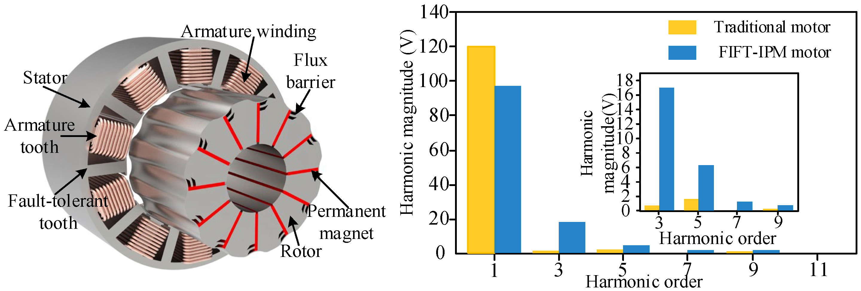
2. Motor Topology Structure and Characteristics

Figure 1 depicts the topological structure of the five-phase FIFT-IPM motor. In order to realize the high stability of inverse saliency characteristics, a slot pole combination of 20-slots/12-poles is adopted. For the stator part, to effectively improve the fault operating capability and the reliability of operation, fractional-slot concentrated windings [56] and an unequal stator width design are applied. In the rotor part, an innovative “flux-barrier guidance” design concept is implemented, featuring larger q-axis magnetic barriers to achieve enhanced inverse-saliency characteristics [39]. This effectively reduces cross-coupling effects within the magnetic circuit [35]. The inductive characteristics of the five-phase FIFT-IPM motor are depicted in Figure 2, showcasing stable parameter variations and pronounced inverse-saliency characteristics [57], thereby validating the design concept’s correctness.
It is worth noting that the five-phase FIFT-IPM motors’ stable parameter characteristics compensate for the MPC algorithms’ reliance on precise motor parameters to some extent. Furthermore, as detailed in the back EMF harmonic analysis diagram in Figure 1, the five-phase FIFT-IPM motor fully retains the third-harmonic content in the back EMF during its design and optimization [41], accounting for approximately 17.5%. This effectively enhances torque output while reducing magnetic saturation effects. The parameters of the five-phase FIFT-IPM motor are listed in Table 1.

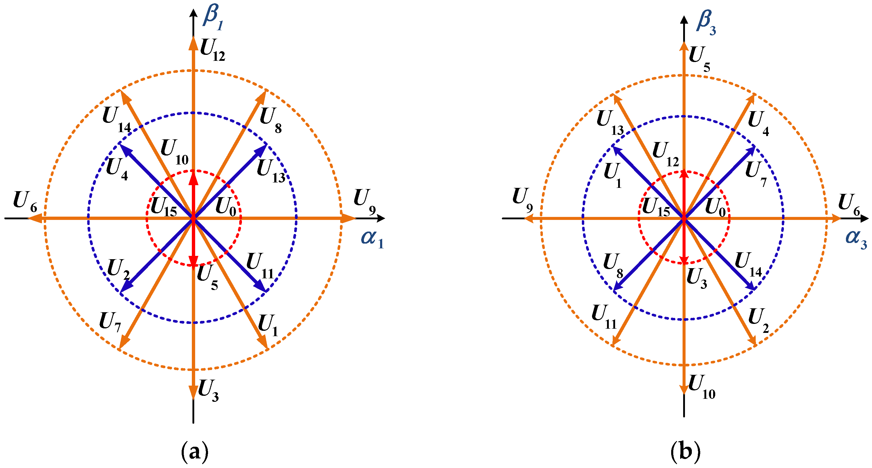
3. Multi-Plane Mathematical Model Under Open-Circuit Fault

Assuming that the phase-A open-circuit fault occurs in the five-phase FIFT-IPM motor, the A phase winding will no longer participate in the electromechanical energy conversion, and the motor is in an asymmetric operation state after the fault. The voltage equation of the remaining four phase windings of the stator after the fault under the ideal state is expressed as
u B u C u D u E = R s i B i C i D i E + L s d d t i B i C i D i E + e B e C e D e E
where uB, uC, uD, uE, iB, iC, iD, iE, eB, eC, eD, and eE are the phase voltage, phase current, and back EMF of the remaining normal phases; Rs is the phase winding resistance; and Ls is the phase inductance of each phase winding.
To achieve fault-tolerant control of the FIFT-IPM motor, it is necessary to make corresponding adjustments to the current in the remaining normal phase. By controlling the fundamental and harmonic currents in this phase and adjusting their amplitude and phase, smooth torque can be obtained, ensuring disturbance-free operation. When a single-phase open-circuit fault occurs in a five-phase FIFT-IPM motor, the control degrees of freedom decrease. The reduced-order Clarke transform matrix, primarily controlling the fundamental plane, can be reconstructed as follows:
T A 1 = 2 5 cos α + m cos 2 α + m cos 3 α + m cos 4 α + m sin α sin 2 α sin 3 α sin 4 α sin 3 α sin 6 α sin 9 α sin 12 α 1 1 1 1
where α represents the angle between the axes of two adjacent phase windings, and m is the correction factor to ensure that the reverse electromotive force remains constant before and after the fault. The value of m is typically −1, and α = 2 π / 5 .
In order to accurately control the third-harmonic plane, a reduced-order Clarke transformation matrix is established with the third-harmonic plane as the main control:
T A 3 = 2 5 cos 3 α 1 cos 6 α 1 cos 9 α 1 cos 12 α 1 sin 3 α sin 6 α sin 9 α sin 12 α sin α sin 2 α sin 3 α sin 4 α 1 1 1 1
To sum up, when the open-circuit fault occurs in the five-phase FIFT-IPM motor, the stator voltage equation in the rotating coordinate system obtained by the reduced-order transformation matrix (2) can be expressed as:
u d 1 = R s i d 1 + L d 1 d i d 1 d t ω e L q 1 i q 1 u q 1 = R s i q 1 + L q 1 d i q 1 d t + ω e L d 1 i d 1 + ω e ψ m 1 u z 1 = R s i z 1 + L z 1 d i z 1 d t + 3 ψ m 3 ω e cos 3 θ e
where Rs represents stator resistance; ωe is the electrical angular velocity; θe is the electrical angle; Ld1 and Lq1 are the inductances of the dq-axis on the fundamental plane; Lz1 is the inductor on the q3-axis; Ψm1 and Ψm3 are the fundamental and third-harmonic components of the stator flux linkage, respectively; ud1, uq1, id1, and iq1 are the voltages and currents in the d1-q1 coordinate system, respectively; and uz1 and iz1 are the third-harmonic voltages and currents, respectively.
When a five-phase motor is in a healthy state, there are 32 voltage vectors in both the fundamental and third-harmonic spaces. However, after an open-circuit fault occurs, the number of voltage vectors in both the fundamental and harmonic spaces is reduced to 16. Figure 3 illustrates spatial distributions of voltage vectors in two subspaces. Different from normal operation, each space plane is divided into 12 sectors under OCF conditions. The remaining unaffected phase voltages are transformed using the first two rows of the reduced-order Clarke matrix shown in Equation (2), resulting in the voltage vector distribution shown in Figure 3a. Similarly, using the first two rows of the reduced-order matrix shown in Equation (3), the voltage vector distribution in the third-harmonic space can be obtained, as shown in Figure 3b. Moreover, the amplitudes of these voltage vectors are classified into six types: 0, 0.145 Udc, 0.325 Udc, 0.441 Udc, 0.447 Udc, and 0.616 Udc, where Udc is the dc-link voltage.

4. Fault-Tolerant Control Strategy for Model Prediction of Multi-Plane Virtual Vector

To address the issue that existing MPC fault-tolerant control strategies cannot effectively track fundamental and third-harmonic currents while maintaining good dynamic and steady-state performance, this paper proposes a multi-plane virtual vector model predictive fault-tolerant control (MPVV-MPFTC) strategy. Additionally, a vector control strategy based on a disturbance observer is introduced, which enhances the resistance of the motor drive system of agricultural electrical equipment to complex environmental disturbances during fault tolerance, ensuring that the steady-state and dynamic performance under fault conditions matches that of normal operation.

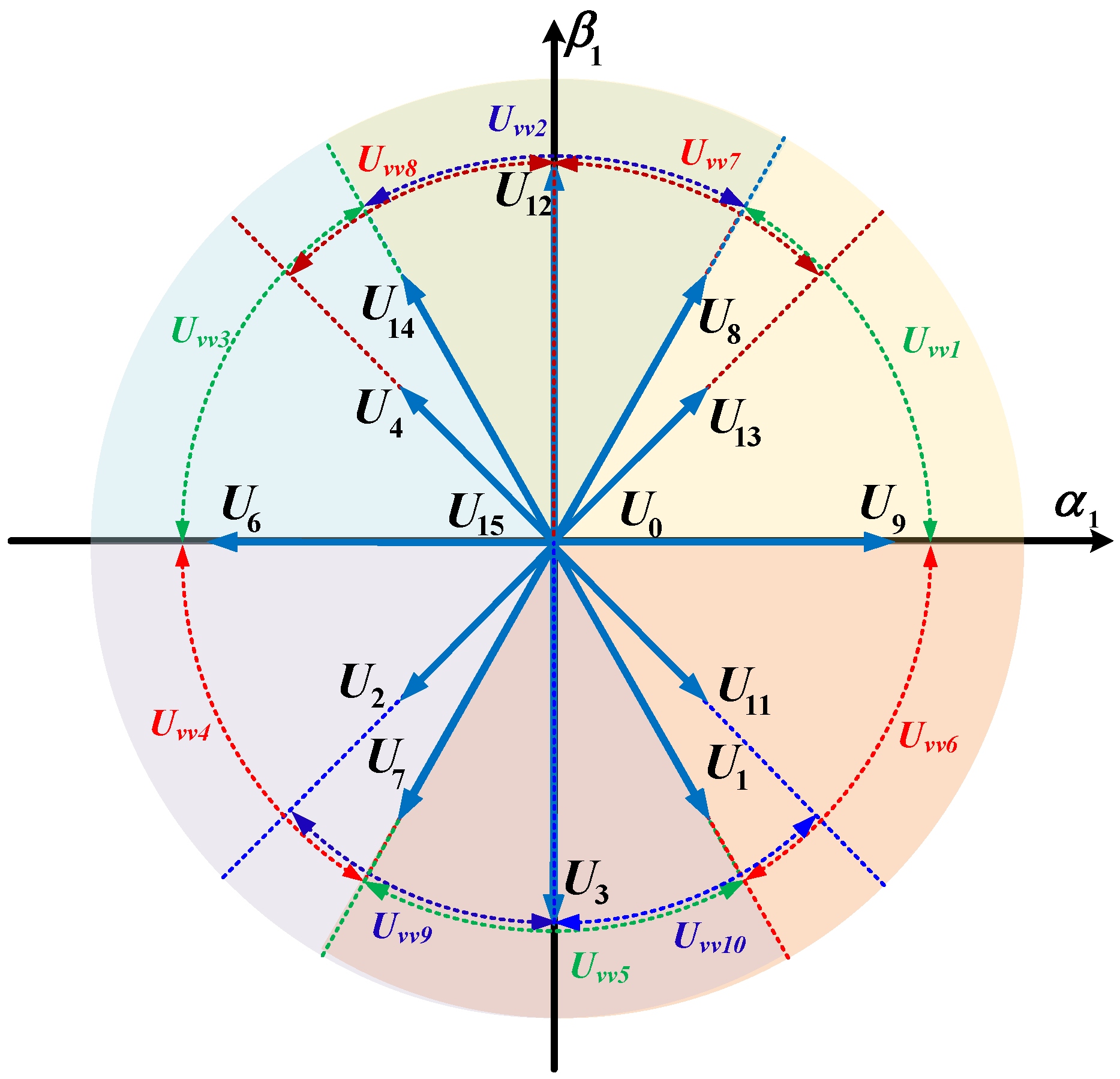
4.1. Virtual Vector Model Prediction Fault-Tolerant Control

This paper introduces the MPVV-MPFTC strategy for addressing open-circuit faults in five-phase FIFT-IPM motors. A key feature of this strategy is that the virtual voltage vectors selected through traversal optimization are equivalent to the sum of three adjacent valid voltage vectors and a zero vector. To meet the requirement of generating standard PWM waveforms, i.e., symmetric PWM waveforms—the fundamental voltage space vector diagram in Figure 3 is referenced. The candidate vector groups listed in Table 2 are designed to generate centrally symmetric pulses, as shown in Figure 4. These six candidate vector groups can synthesize six virtual voltage vectors with variable direction and amplitude, effectively covering any direction and amplitude. Consequently, the proposed strategy achieves more precise tracking of fundamental and third-harmonic currents.
In addition to the three basic voltage vectors shown in Table 2, the pre-synthesized virtual vector also contains a zero vector, and its synthesis formula is
T s U v v n = T 1 U 1 + T 2 U I I + T 3 U I I I + T 0 U I V
where n ranges from 1 to 6, and UI, UII, UIII, and UIV represent the basic voltage vectors I, II, III, and IV, respectively. T1, T2, T3, and T0 are the times of the three basic vectors and the time of the zero vector, respectively, and Ts is a control period.

4.2. Computational Optimization of Multi-Plane Virtual Vector Model Prediction Fault Tolerance Control

The computational load of the proposed control strategy primarily involves calculating the action time for each vector group. To avoid wasting computational resources, the reference voltage is derived from the reference current to determine the position of the target voltage vector, thereby defining the traversal sectors. This approach reduces traversal steps and optimizes computation time. The reference voltage uα1, uβ1 in the stationary coordinate system is obtained using the feedback current and the given current. By referencing the voltage sectors in Table 3, the traversal sectors for the expected voltage vector in the next moment can be quickly identified, as illustrated in Figure 5. Each sector contains three candidate virtual vectors, reducing the original six traversal optimization calculations to just three. This significantly lightens the computational load while maintaining algorithm speed. As shown in Table 4, the improved algorithm expands the total number of virtual vectors to ten, which enhances tracking accuracy.

4.3. Calculation of Vector Action Time

The MPVV-MPFTC strategy proposed in this paper uses the principle of no difference beat to calculate the vector action time. When the traversing sector is determined, the action time of each basic vector and zero vector in the three vector groups within the sector will be calculated according to the given current and feedback current. The expression for action time calculation is
i d 1 k + 1 i q 1 k + 1 i z 1 k + 1 = i d 1 k i q 1 k i z 1 k + Δ d 1 _ 1 Δ q 1 _ 1 Δ z 1 _ 1 Δ d 1 _ 2 Δ q 1 _ 2 Δ z 1 _ 2 Δ d 1 _ 3 Δ q 1 _ 3 Δ z 1 _ 3 Δ d 1 _ 0 Δ q 1 _ 0 Δ z 1 _ 0 T 1 T 2 T 3 T 0 = i d 1 i q 1 i z 1
where id1(k + 1), iq1(k + 1), and iz1(k + 1) represent the predicted values of the current for the next moment on the d1 axis, q1 axis, and z1 axis, respectively; id1*, iq1*, and iz1* are the reference values of the current; id1(k), iq1(k), and iz1(k) are the feedback values of the current at this moment; Δ d1_n (n = 0,1,2,3), Δ q1_n (n = 0,1,2,3), and Δ z1_n (n = 0,1,2,3) are the rates of increase in current on the d1-axis, q1-axis, and y1-axis, respectively, for different basic voltage vectors in the candidate vector group.
In addition, the vector action time satisfies the following relation:
T s = T 1 + T 2 + T 3 + T 0
Substituting Equation (7) into Equation (6), we can get the action time of each basic vector in the preselected vector group:
T 1 T 2 T 3 = Δ d 1 _ 1 Δ d 1 _ 0 Δ d 1 _ 2 Δ d 1 _ 0 Δ d 1 _ 3 Δ d 1 _ 0 Δ q 1 _ 1 Δ q 1 _ 0 Δ q 1 _ 2 Δ q 1 _ 0 Δ q 1 _ 3 Δ q 1 _ 0 Δ z 1 _ 1 Δ z 1 _ 0 Δ z 1 _ 2 Δ z 1 _ 0 Δ z 1 _ 3 Δ z 1 _ 0 1 i d 1 i d 1 k Δ d 1 _ 0 T s i q 1 i d 1 k Δ q 1 _ 0 T s i z 1 i z 1 k Δ z 1 _ 0 T s
When the zero vector acts, the slope of the axial current for the d1-axis, q1-axis, and z1-axis is expressed as
Δ d 1 _ 0 = 1 L d ω e L q 1 i q 1 R s i d 1 Δ q 1 _ 0 = 1 L q ω e L d 1 i d 1 R s i q 1 ω e ψ m 1 Δ z 1 _ 0 = 1 L z 1 R s i z 3 ω e ψ m 3 cos 3 θ e
When the basic vector Un (n = I, II, III, IV) acts on the d1-axis, q1-axis, and z1-axis, the expression for the current slope of the axis is
Δ d 1 _ n = Δ d 1 _ 0 + u d 1 _ n L d Δ q 1 _ n = Δ q 1 _ 0 + u q 1 _ n L q Δ z 1 _ n = Δ z 1 _ 0 + u z 1 _ n L z 1
where ud1_n, uq1_n, and uz1_n represent the basic vectors for the uncorrelated d1-axis, q1-axis, and z1-axis voltage.
After obtaining the action times of each basic vector in the three preselected vector groups within the traversed sector, the vectors are synthesized to form three virtual vectors. These virtual vectors are then sequentially substituted into the model for prediction at the next moment, and optimization based on a cost function is performed. This process selects the candidate virtual voltage vectors that most closely match the desired voltage vector, thereby achieving the optimal control effect. The prediction model is as follows:
i d 1 k + 1 = i d 1 k + T s L d u v v _ d + ω e L q i q 1 k R s i d 1 k i q 1 ( k + 1 ) = i q 1 k + T s L q u v v _ q ω e L d i d 1 k R S i q 1 k ω e ψ f i z 1 k + 1 = i z 1 ( k ) + T s L z 1 u v v _ z 1 R s i z 1 k 3 ω e ψ f 3 cos 3 θ
where uvv_d, uvv_q, and uvv_z represent the voltage vectors corresponding to the d1-axis, q1-axis, and z1-axis, respectively.
In order to achieve accurate tracking of the current, and due to the existence of the third-harmonic, it is necessary to strictly control the z1-axis component, so the general cost function is set as
J = i d 1 i d 1 k + 1 2 + i q 1 i q 1 k + 1 2 + i z 1 i z 1 k + 1 2
Since the candidate virtual vector to be traversed is reduced to three, after three traverses in Equation (11), the three groups of predicted currents are substituted into the value function for optimization. Finally, select the optimal virtual voltage vector Uvvn, which is closest to the expected voltage vector U0.

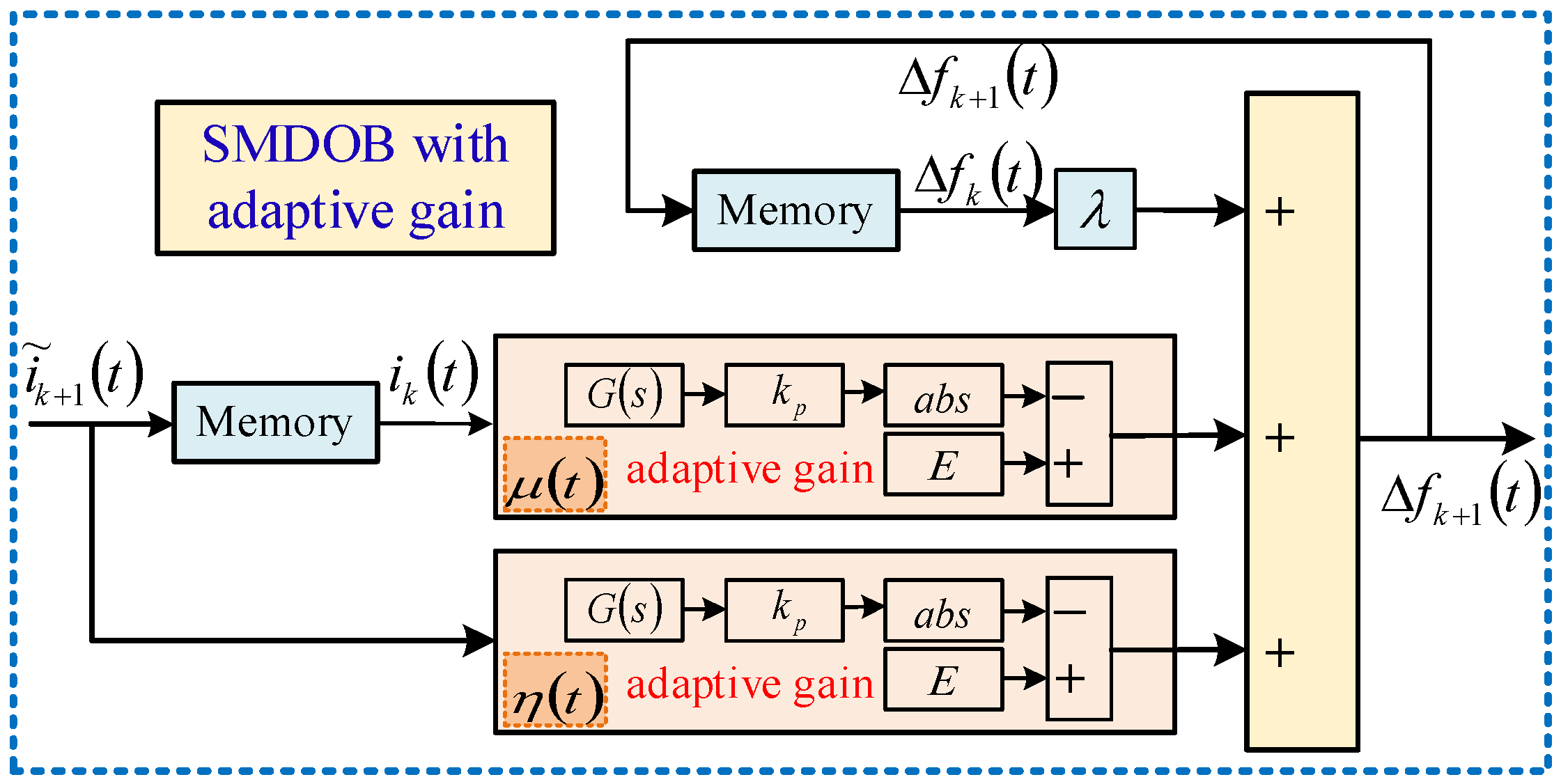
4.4. Sliding-Mode Disturbance Observer

To improve the resistance of fault-tolerant control systems of electrical agricultural equipment to interference under the MPVV-MPFTC strategy, this paper innovatively proposes a novel sliding mode disturbance observer (SMDOB) with adaptive gain. By introducing an adaptive factor into SMDOB, it can effectively eliminate current harmonics caused by faults. At the same time, compared to traditional disturbance observers, the accuracy of estimated parameters has been significantly improved. The key to the proposed SMDOB with adaptive gain lies in estimating complex disturbances and feeding them back into the control system.
When the interference signal appears, its time-domain differential equation can be expressed as
x ˙ = A x + B 0 u + B 1 d
where u and d represent the standard model signal and interference signal, respectively. A, B0, and B1 are the corresponding coefficient matrices.
Suppose the system disturbance changes slowly:
d ˙ = 0
where d represents the disturbance to be observed in the control system.
In the context of a fault-tolerant control system experiencing a fault state, the tracking error attributable to torque pulsation is observed to escalate. Consequently, the tracking error of the q1-axis current can be classified as a disturbance, which in turn can be denoted as variable x.
x = i ˜ q i q
It is imperative to recognize that the discontinuity inherent in the switching function of conventional linear sliding surfaces can result in pronounced jitter, which may degrade the dynamic performance of the system and potentially lead to instability and collapse. To mitigate this challenge, an integral term is incorporated into the traditional sliding surface, thereby creating an integral sliding surface. The formulation of this surface is as follows:
S x = x + c 0 x x d τ
where c is the integral factor. It should be noted that if the value of c is too large, the jitter of the sliding mode controller will increase. After incorporating the integral term, the steady-state error is reduced, the jitter is mitigated, and the stability of the controller can be enhanced.
To enhance the robustness of the fault-tolerant control system, in accordance with the strong robust law, a function x/(|x| + δ) is introduced to construct the sliding mode control rate of the SMDOB with adaptive gain, which can be expressed as
G s = S ˙ = ε 1 x x + δ s i g n S ε 2 S
where ε1 and ε2 are the isokinetic approach coefficient and exponential reaching coefficient. When ε1 and ε2 increase, the sliding mode surface becomes faster. δ is the adjustment factor, satisfying the condition 0 ≤ δ ≤ 1.
η s = μ s = E k G s
where k represents the gain factor, and E denotes the ideal gain.
The control rate of the control system can be described as
Δ f k + 1 t = λ Δ f k t + μ t i e , k t + η t i e , k + 1 t
where the parameter λ is the forgetting factor, which represents a periodic harmonic transformation. According to Equation (19), the control block diagram of the SMDOB module with adaptive gain is shown in Figure 6.
From Equations (16) and (17), it can be seen that the adaptive gain SMDOB is designed based on the concept of dynamic compensation. This reduces current harmonics and enhances the fault-tolerant control systems’ disturbance rejection capability and dynamic performance. Compared to conventional solutions, the linear DOB suffers from accuracy degradation under parameter perturbations due to its reliance on a nominal model; the Extended State Observer (ESO) has limited bandwidth; the fixed-gain SMO tends to induce chattering. The proposed SMDOB integrates the robustness of sliding mode control with an adaptive gain mechanism: By dynamically adjusting gains through the reaching law, it achieves an optimal balance between rapid disturbance estimation and chattering suppression. In summary, the proposed controller exhibits good robustness under faulty conditions.

5. Overall Control Strategy

For the single-phase open-circuit fault in FIFT-IPM motors, the overall control block diagram of the proposed MPVV-MPFTC strategy is illustrated in Figure 7. Unlike traditional MPC approaches that neglect or apply open-loop processing to harmonic plane control, our fault-tolerant strategy utilizes independent reduced-order transformation matrices for both fundamental and harmonic planes. This achieves synchronous closed-loop precise control of fundamental and harmonic currents. Furthermore, computational load optimization is implemented for the traversal optimization process within the MPVV-MPFTC module, enabling rapid and effective control of both planes. On the other hand, to adapt to the multi-disturbance agricultural environment, the strategy incorporates an adaptive-gain SMDOB. This provides dynamic compensation through feedforward action, while its adaptive gain mechanism adjusts observer gains in real-time based on system states. These significantly enhance the system’s ability to withstand complex environmental disturbances during faults, ensuring robust operation of the fault-tolerant control system in agricultural applications.

6. Experimental Verification

To verify the feasibility of the proposed model predictive fault-tolerant control strategy and the accuracy of the disturbance observer theory analysis, this paper constructs an experimental platform for a five-phase FIFT-IPM motor. The experimental platform is shown in Figure 8, which mainly includes an inverter and a magnetic powder brake. The switching commands are generated by the dSPACE 1007 (dSPACE Mechatronic Control Technology, Paderborn, Germany), with the sampling frequency and inverter switching frequency both set to 10 kHz. The magnetic powder brake acts as a load, while the torque sensor is used to obtain the torque signal. To validate the improvement of the steady-state performance of the proposed anti-disturbance multi-plane virtual vector model predictive fault-tolerant control strategy, the experimental results of the MPVV-MPFTC strategy and the traditional single-vector MPFTC strategy under duty cycle optimization were analyzed and compared, and they are, respectively, referred to as Method A and Method B.

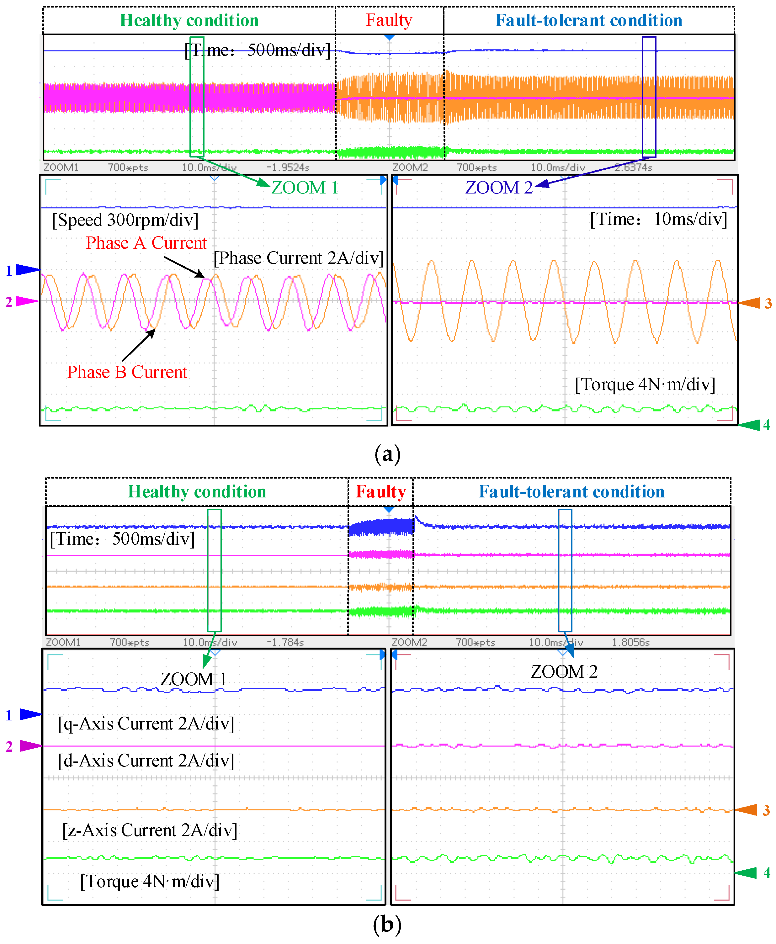
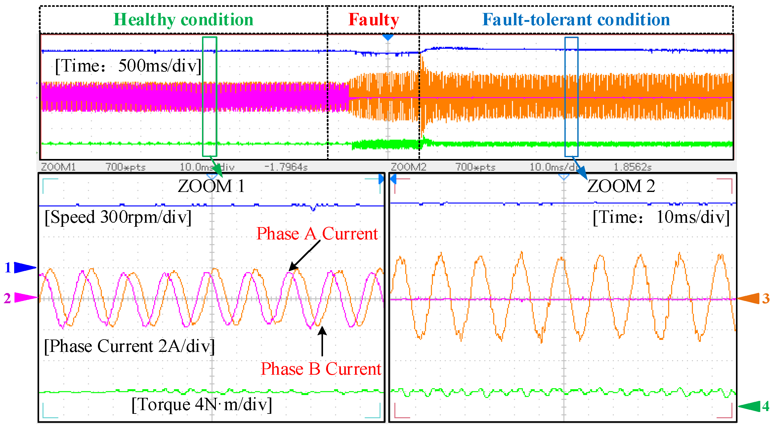
6.1. Fault-Tolerant Control Switching Experiment of Motor Drive System

Figure 9a and Figure 10 present the performance comparison between Method A and Method B during the transition from a healthy state to a fault-tolerant state. The experimental results show that under normal operating conditions, torque and speed remain relatively stable, with phase currents exhibiting standard sine waveforms. After implementing fault-tolerant control, Figure 9a shows that the remaining phase currents quickly return to sine waveforms, the speed rapidly recovers, and torque pulsation is significantly reduced. Meanwhile, the harmonic components of iq1 and id1 in Figure 9b drop sharply after fault tolerance. The fault-tolerant control switching experiments have demonstrated that the proposed Scheme A can ensure continuous operation of the motor without shutdown under fault conditions. Compared to Method B, Scheme A exhibits higher sinusoidal quality in its fault-tolerant phase currents, which can be attributed to its implementation of the deadbeat principle for calculating the action durations of multiple voltage vectors. This approach demonstrates superior advantages in current tracking performance.

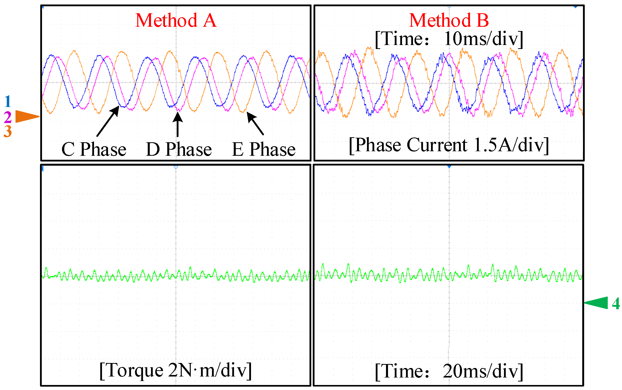
6.2. Steady State Performance Test of Motor Drive System

To comprehensively evaluate the performance of the proposed strategy under stable conditions, Figure 11 presents a comparison chart of the d1-axis, q1-axis, and z1-axis currents as well as the electromagnetic torque of the motor at 600 r/min speed. The experimental results show that Method A significantly outperforms Method B in suppressing harmonic currents in the fundamental wave space, i.e., iz1, which leads to smaller pulsations of iq1 and id1 after fault tolerance. Figure 12 further reveals the comparison of phase currents C, D, and E with electromagnetic torque when the motor operates at 400 r/min. Other experimental data sampling analyses are detailed in Table 5. It is evident that the proposed fault-tolerant control strategy A achieves an average reduction of 55% in phase current distortion rate and a 10.88% decrease in torque ripple compared to conventional Method B.
After a comprehensive analysis of the experimental data, it can be concluded that the proposed strategy has significant advantages in stability performance, effectively reducing current distortion rates and torque pulsations, thereby enhancing the stable operation quality of the motor.

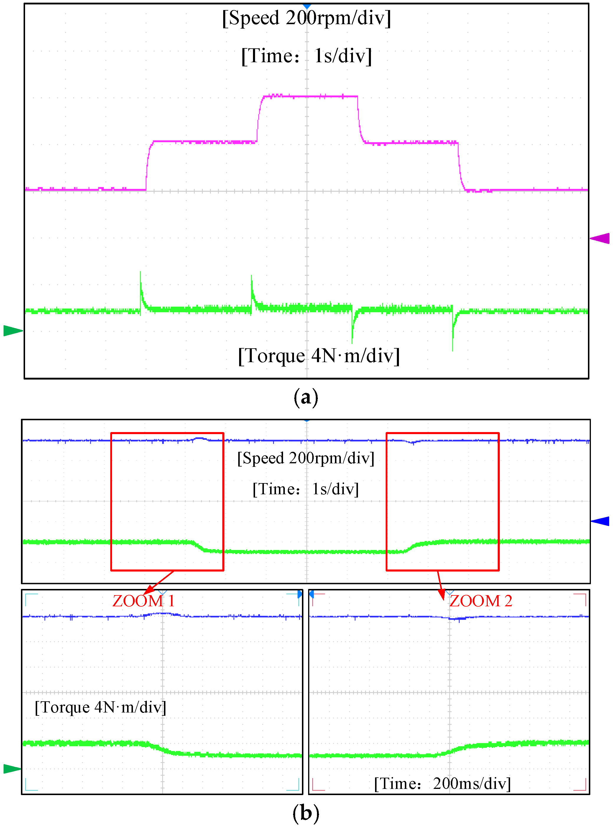
6.3. Dynamic Performance Test of Motor Drive System

To verify the dynamic stability performance of the proposed fault-tolerant control strategy, Figure 13 shows the experimental waveforms for speed response and variable load response. In the speed response test, Figure 13a presents the waveform of speed versus torque. This experiment demonstrates that the actual speed can quickly follow the set speed reference value, whether accelerating or decelerating, with a response time controlled below 0.2 s. The speed curve maintains good smoothness, which proves the excellent performance of the MPVV-MPFTC strategy in speed response. In the variable load response test, Figure 13b illustrates the speed response under varying loads. Specifically, when the load decreases, the speed can recover to the reference value within about 0.35 s, with an overshoot of only 1.4%; whereas when the load increases, the response time is approximately 0.3 s, with an overshoot of about 1.7%. These experimental results indicate that the fault-tolerant control strategy has good robustness against load disturbances, ensuring stable operation of the motor under load variations.

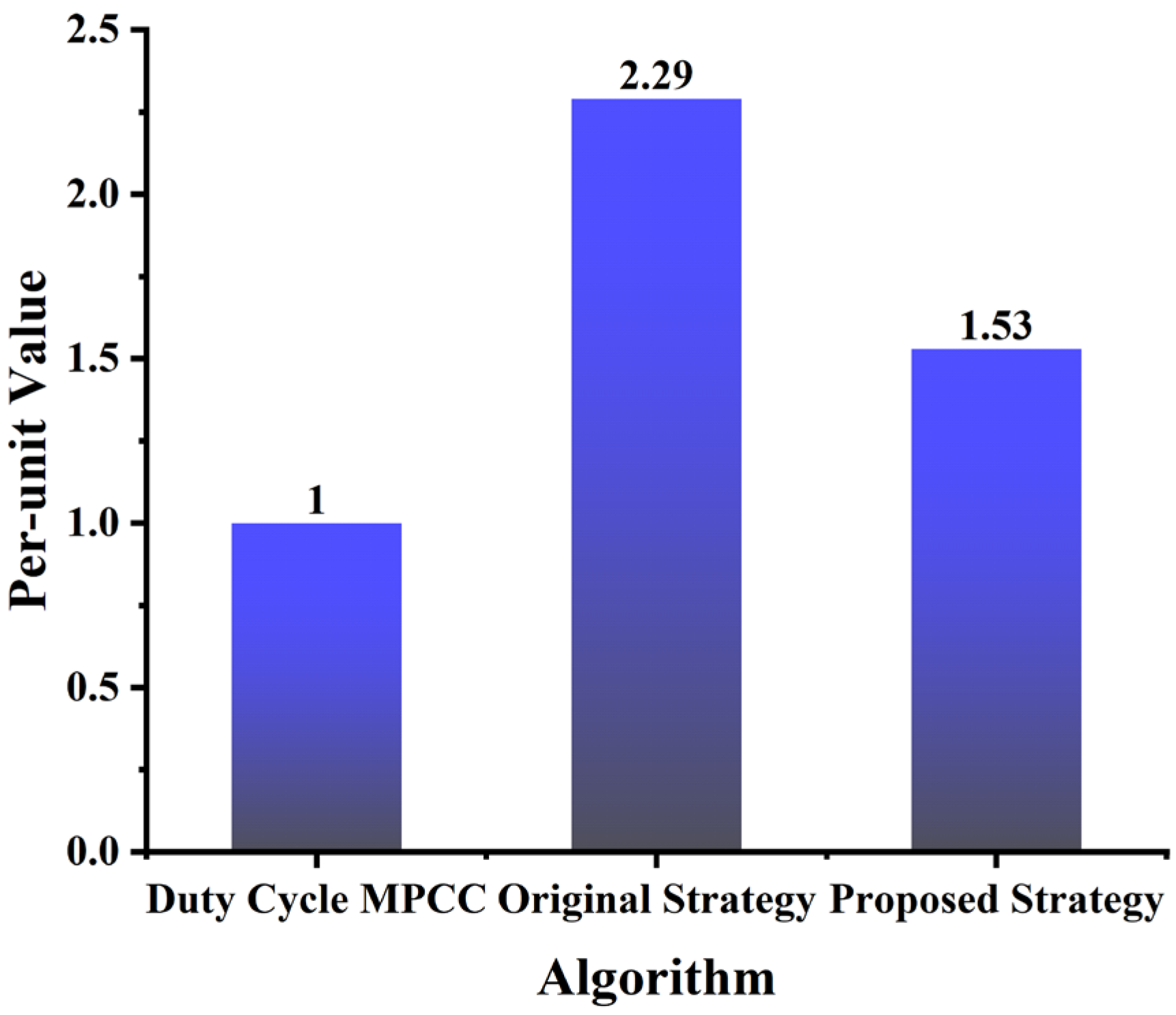
6.4. Analysis of Calculation Amount of Motor Drive System

The computational load of control strategies in drive systems critically determines their operational speed and practical applicability. To intuitively evaluate the computational load of the proposed fault-tolerant control strategy, this paper adopts the single-vector MPFTC strategy with duty ratio optimization as a reference benchmark. A normalized processing of computation time was implemented to explicitly reveal the relative computational complexity among different algorithms, with detailed data presented in Figure 14. The enhanced algorithm demonstrates a 33.3% reduction in computational load compared to the original methodology presented in this work, achieved through refined traversal optimization procedures and streamlined computational workflows, thereby significantly accelerating algorithmic execution. Although exhibiting a 52.94% increase in computation time relative to duty-cycle-optimized fault-tolerant control methods, the substantial improvements in control performance justify this computational trade-off. In practical implementations, the superior control efficacy sufficiently compensates for the additional computational resource allocation, validating its high cost-effectiveness in industrial applications.

7. Conclusions

In light of single-phase open-circuit faults of five-phase FIFT-IPM motors used in electrical agricultural equipment, this paper proposes a multi-plane virtual vector model predictive fault-tolerant control strategy to achieve better control performance. In addition, a sliding-mode disturbance observer based on adaptive gain is proposed, which dynamically adjusts the gain according to the real-time state of the system so that it can better operate in a multi-disturbance agricultural application environment under fault conditions and effectively guarantees the good robustness of the fault-tolerant control system in fault conditions. This fault tolerance strategy has the following advantages:
(1) The proposed MPVV-MPFTC strategy contains multiple basic voltage vectors during the control period, and the modulation range can cover any direction and any amplitude and is calculated using the principle of no-beat. Vector action time can track multi-plane current more effectively and has a good control effect. Compared with traditional duty-cycle-optimized single-vector MPFTC, the proposed strategy achieves a 55% average reduction in current distortion rate and a 10.88% decrease in torque ripple;
(2) After dividing the traversal sectors in the proposed algorithm, the computational load is reduced by 33.3% compared to the original algorithm, thereby saving the processor’s computing resources;
(3) The sliding mode disturbance observer based on adaptive gain can better resist disturbances under fault conditions, effectively ensuring that the fault-tolerant control system has good robustness in agricultural application environments.

Author Contributions

Conceptualization, H.C. and L.Z.; methodology, H.C., K.X. and L.Z.; software, H.C. and K.X.; validation, H.C. and L.Z.; writing-original draft, H.C., K.X., L.Z., Z.L. and Z.W.; formal analysis, K.X., L.Z. and Z.L.; investigation, Z.W.; data curation, L.Z., Z.W. and H.F.; project administration L.Z.; writing—review and editing, Z.L. and H.F. All authors have read and agreed to the published version of the manuscript.

Funding

This research was supported in part by the National Natural Science Foundation of China under Grant 52277051.

Data Availability Statement

The original contributions presented in this study are included in the article. Further inquiries can be directed to the corresponding author.

Conflicts of Interest

The authors declare no conflicts of interest.

References

  1. Yu, Y.; Hao, S.; Guo, S.; Tang, Z.; Chen, S. Motor Torque Distribution Strategy for Different Tillage Modes of Agricultural Electric Tractors. Agriculture 2022, 12, 1373. [Google Scholar] [CrossRef]
  2. Zhu, Z.; Chai, X.; Xu, L.; Quan, L.; Yuan, C.; Tian, S. Design and performance of a distributed electric drive system for a series hybrid electric combine harvester. Biosyst. Eng. 2023, 236, 160–174. [Google Scholar] [CrossRef]
  3. Zhu, Z.; Zeng, L.; Chen, L.; Zou, R.; Cai, Y. Fuzzy Adaptive Energy Management Strategy for a Hybrid Agricultural Tractor Equipped with HMCVT. Agriculture 2022, 12, 1986. [Google Scholar] [CrossRef]
  4. Han, J.; Wang, F. Design and Testing of a small orchard tractor driven by a power battery. Eng. Agrícola 2023, 43, e20220195. [Google Scholar]
  5. Zhu, Q.; Zhu, Z.; Zhang, H.; Gao, Y.; Chen, L. Design of an Electronically Controlled Fertilization System for an Air-Assisted Side-Deep Fertilization Machine. Agriculture 2023, 13, 2210. [Google Scholar] [CrossRef]
  6. Li, Y.; Xu, L.; Lv, L.; Shi, Y.; Yu, X. Study on Modeling Method of a Multi-Parameter Control System for Threshing and Cleaning Devices in the Grain Combine Harvester. Agriculture 2022, 12, 1483. [Google Scholar] [CrossRef]
  7. Li, H.; Chen, L.; Zhang, Z. A Study on the Utilization Rate and Influencing Factors of Small Agricultural Machinery: Evidence from 10 Hilly and Mountainous Provinces in China. Agriculture 2023, 13, 51. [Google Scholar] [CrossRef]
  8. Liu, H.; Yan, S.; Shen, Y.; Li, C.; Zhang, Y.; Hussain, F. Model predictive control system based on direct yaw moment control for 4WID self-steering agriculture vehicle. Int. J. Agric. Biol. Eng. 2021, 14, 175–181. [Google Scholar] [CrossRef]
  9. Gao, Y.; Feng, K.; Yang, S.; Han, X.; Wei, X.; Zhu, Q.; Chen, L. Design and Experiment of an Unmanned Variable-Rate Ferti-lization Control System with Self-Calibration of Fertilizer Discharging Shaft Speed. Agronomy 2024, 14, 2336. [Google Scholar] [CrossRef]
  10. Yue, R.; Yao, M.; Zhang, T.; Shi, J.; Zhou, J.; Hu, J. Design and Experiment of Dual-Row Seedling Pick-Up Device for High-Speed Automatic Transplanting Machine. Agriculture 2024, 14, 942. [Google Scholar] [CrossRef]
  11. Shi, Q.; Liu, D.; Mao, H.; Shen, B.; Li, M. Wind-induced response of rice under the action of the downwash flow field of a multi-rotor UAV. Biosyst. Eng. 2021, 203, 60–69. [Google Scholar] [CrossRef]
  12. Ahmed, S.; Qiu, B.; Ahmad, F.; Kong, C.W.; Xin, H. A state-of-the-art analysis of obstacle avoidance methods from the per-spective of an agricultural sprayer UAV’s operation scenario. Agronomy 2021, 11, 1069. [Google Scholar] [CrossRef]
  13. Li, J.; Shang, Z.; Li, R.; Cui, B. Adaptive Sliding Mode Path Tracking Control of Unmanned Rice Transplanter. Agriculture 2022, 12, 1225. [Google Scholar] [CrossRef]
  14. Liu, W.; Zhou, J.; Zhang, T.; Zhang, P.; Yao, M.; Li, J.; Sun, Z.; Ma, G.; Chen, X.; Hu, J. Key Technologies in Intelligent Seeding Machinery for Cereals: Recent Advances and Future Perspectives. Agriculture 2025, 15, 8. [Google Scholar] [CrossRef]
  15. Yang, S.; Zhai, C.; Gao, Y.; Dou, H.; Zhao, X.; He, Y.; Wang, X. Planting Uniformity Performance of Motor-Driven Maize Precision Seeding Systems. Int. J. Agric. Biol. Eng. 2022, 15, 101–108. [Google Scholar] [CrossRef]
  16. Tang, L.; Wang, W.; Zhang, C.; Wang, Z.; Ge, Z.; Yuan, S. Linear Active Disturbance Rejection Control System for the Travel Speed of an Electric Reel Sprinkling Irrigation Machine. Agriculture 2024, 14, 1544. [Google Scholar] [CrossRef]
  17. Chen, Y.; Chen, L.; Wang, R.; Xu, X.; Shen, Y.; Liu, Y. Modeling and test on height adjustment system of electrically-controlled air suspension for agricultural vehicles. Int. J. Agric. Biol. Eng. 2016, 9, 40–47. [Google Scholar]
  18. Zhu, Z.; Yang, Y.; Wang, D.; Cai, Y.; Lai, L. Energy Saving Performance of Agricultural Tractor Equipped with Mechan-ic-Electronic-Hydraulic Powertrain System. Agriculture 2022, 12, 436. [Google Scholar] [CrossRef]
  19. Liu, J.; Xia, C.; Jiang, D.; Sun, Y. Development and testing of the power transmission system of a crawler electric tractor for greenhouses. Appl. Eng. Agric. 2020, 36, 797–805. [Google Scholar] [CrossRef]
  20. Hu, J.; Zhao, X.; Liu, W.; Yao, M.; Zhao, J. Development of a Seeding Control Method Based on Seed Height in the Hopper of a Precision Wheat Drill. Appl. Eng. Agric. 2021, 37, 1131–1138. [Google Scholar] [CrossRef]
  21. Yuan, J.; Ji, W.; Feng, Q. Robots and Autonomous Machines for Sustainable Agriculture Production. Agriculture 2023, 13, 1340. [Google Scholar] [CrossRef]
  22. Shi, J.; Hu, J.; Li, J.; Liu, W.; Yue, R.; Zhang, T.; Yao, M. Design and Experiment of Planting Mechanism of Automatic Trans-planter for Densely Planted Vegetables. Agriculture 2024, 14, 1357. [Google Scholar] [CrossRef]
  23. Lu, E.; Xue, J.; Chen, T.; Jiang, S. Robust Trajectory Tracking Control of an Autonomous Tractor-Trailer Considering Model Parameter Uncertainties and Disturbances. Agriculture 2023, 13, 869. [Google Scholar] [CrossRef]
  24. Lu, E.; Ma, Z.; Li, Y.M.; Xu, L.Z.; Tang, Z. Adaptive backstepping control of tracked robot running trajectory based on real-time slip parameter estimation. Int. J. Agric. Biol. Eng. 2020, 13, 178–187. [Google Scholar] [CrossRef]
  25. Lu, E.; Xu L, Z.; Li Y, M.; Tang, Z.; Ma, Z. Modeling of working environment and coverage path planning method of combine harvesters. Int. J. Agric. Biol. Eng. 2020, 13, 132–137. [Google Scholar] [CrossRef]
  26. Yan, H.F.; Acquah, S.J.; Zhang, J.Y.; Wang, G.Q.; Zhang, C.; Darko, R.O. Overview of modelling techniques for greenhouse microclimate environment and evapotranspiration. Int. J. Agric. Biol. Eng. 2021, 14, 1–8. [Google Scholar] [CrossRef]
  27. Zhu, Y.; Cui, B.; Yu, Z.; Gao, Y.; Wei, X. Tillage Depth Detection and Control Based on Attitude Estimation and Online Cali-bration of Model Parameters. Agriculture 2024, 14, 2130. [Google Scholar] [CrossRef]
  28. Dai, D.; Chen, D.; Wang, S.; Li, S.; Mao, X.; Zhang, B.; Wang, Z.; Ma, Z. Compilation and Extrapolation of Load Spectrum of Tractor Ground Vibration Load Based on CEEMDAN-POT Model. Agriculture 2023, 13, 125. [Google Scholar] [CrossRef]
  29. Zhang, B.; Bai, T.; Wu, G.; Wang, H.; Zhu, Q.; Zhang, G.; Meng, Z.; Wen, C. Fatigue Analysis of Shovel Body Based on Tractor Subsoiling Operation Measured Data. Agriculture 2024, 14, 1604. [Google Scholar] [CrossRef]
  30. Yan, H.; Acquah, S.J.; Zhang, C.; Wang, G.; Huang, S.; Zhang, H.; Zhao, B.; Wu, H. Energy partitioning of greenhouse cucumber based on the application of Penman-Monteith and Bulk Transfer models. Agric. Water Manag. 2019, 217, 201–211. [Google Scholar] [CrossRef]
  31. Sun, J.; Wang, Z.; Ding, S.; Xia, J.; Xing, G. Adaptive disturbance observer-based fixed time nonsingular terminal sliding mode control for path-tracking of unmanned agricultural tractors. Biosyst. Eng. 2024, 246, 96–109. [Google Scholar] [CrossRef]
  32. Zhu, S.; Wang, B.; Pan, S.; Ye, Y.; Wang, E.; Mao, H. Task Allocation of Multi-Machine Collaborative Operation for Agricultural Machinery Based on the Improved Fireworks Algorithm. Agronomy 2024, 14, 710. [Google Scholar] [CrossRef]
  33. Li, J.; Wu, Z.; Li, M.; Shang, Z. Dynamic Measurement Method for Steering Wheel Angle of Autonomous Agricultural Vehicles. Agriculture 2024, 14, 1602. [Google Scholar] [CrossRef]
  34. Pei, Z.; Zhang, L.; Fu, H.; Wang, Y. New Fault-Tolerant Sensorless Control of FPFTPM Motor Based on Hybrid Adaptive Robust Observation for Electric Agricultural Equipment Applications. Energies 2025, 18, 1962. [Google Scholar] [CrossRef]
  35. Zhang, L.; Zhang, M.; Zhu, X.; Pei, Z.; Chen, X. Space Decoupling Sensorless Control of Five-Phase Flux-Intensifying PM Motor Based on AFCCF-SMO Considering Flux-Weakening Operation. IEEE. Trans. Ind. Electron. 2025, 72, 6865–6875. [Google Scholar] [CrossRef]
  36. Zhu, H.; Zhang, L.; Peng, Z.; Tan, F.; Xu, L. New Low-Noise Sensorless Control Strategy for PMSM Drives Based on Variable-Frequency Voltage Signal Injection. IET Electr. Power Appl. 2025, 19, e12538. [Google Scholar] [CrossRef]
  37. Wu, T.; Zhu, H.; Wu, X.; Huang, S.; Yu, X.; Tan, Z.; Gao, F.; Tong, X. Enhanced Sequential High-Frequency Voltage Injection Method for Low-Speed Sensorless Control of IPMSM. IEEE Trans. Power. Electron. 2025, 40, 10836–10845. [Google Scholar] [CrossRef]
  38. Marcos-Andrade, D.; Beltran-Carbajal, F.; Rivas-Cambero, I.; Yañez-Badillo, H.; Favela-Contreras, A.; Rosas-Caro, J.C. Sliding Mode Speed Control in Synchronous Motors for Agriculture Machinery: A Chattering Suppression Approach. Agriculture 2024, 14, 737. [Google Scholar] [CrossRef]
  39. Zhang, L.; Deng, S.; Zhu, X.; Xiang, Z. New Flux Intensifying Technique for Five-Phase Fault-Tolerant Interior Permanent Magnet Motors Under Multiple Sensorless Operation. IEEE. Trans. Ind. Electron. 2024, 71, 13801–13811. [Google Scholar] [CrossRef]
  40. Zhang, L.; Li, X.; Zhu, X.; Zhang, C. Design and Optimization of a Five-Phase Reverse-Salient Fault-Tolerant Permanent Magnet Motor for Electric Vehicles. IEEE Trans. Ind. Electron. 2025, 72, 6762–6774. [Google Scholar] [CrossRef]
  41. Zhang, L.; Wang, X.; Zhu, X.; Chen, X.; Chen, C. Extended Multioperating Mode Control Strategy for Five-Phase Flux-Intensifying Interior Permanent Magnet Motor Based on VSI-MTPA and FW Control. IEEE Trans. Transp. Electrif. 2025, 11, 1518–1528. [Google Scholar] [CrossRef]
  42. Li, T.; Sun, X.; Lei, G.; Guo, Y.; Yang, Z.; Zhu, J. Finite-Control-Set Model Predictive Control of Permanent Magnet Synchronous Motor Drive Systems—An Overview. IEEE-CAA J. Autom. Sin. 2022, 9, 2087–2105. [Google Scholar] [CrossRef]
  43. Dawood, A.; Ismeil, M.A.; Hussein, H.S.; Hasaneen, B.M.; Abdel-Aziz, A.M. An Efficient Protection Scheme Against Single-Phasing Fault for Three-Phase Induction Motor. IEEE Access 2024, 12, 6298–6317. [Google Scholar] [CrossRef]
  44. Li, B.; Lin, H. A novel quick startup control scheme for interior permanent magnet synchronous motor based on optimal voltage vector. In Proceedings of the 2010 2nd International Asia Conference on Informatics in Control, Automation and Robotics (CAR 2010), Wuhan, China, 6–7 March 2010; pp. 104–107. [Google Scholar]
  45. Zhu, C.; Wang, H.; Liu, W.; Li, H.; Xiao, Z. Torque Ripple Suppression method of Doubly Salient Electro-Magnetic Machine Based on Direct Instantaneous Torque Control. In Proceedings of the 2022 25th International Conference on Electrical Machines and Systems (ICEMS), Chiang Mai, Thailand, 29 November–2 December 2022; pp. 1–6. [Google Scholar]
  46. Wei, Z.; Jiang, X.; Yang, S.; Zhang, X.; Cai, Y.; Wang, S. Research on Fault-Tolerant Control Strategy of Fault-Tolerant Permanent Magnet Motor Based on Cascaded Model Prediction Algorithm. In Proceedings of the 2022 25th International Conference on Electrical Machines and Systems (ICEMS), Chiang Mai, Thailand, 29 November–2 December 2022; pp. 1–6. [Google Scholar]
  47. Huang, W.; Hua, W.; Chen, F.; Yin, F.; Qi, J. Model predictive current control of open-circuit fault-tolerant five-phase flux-switching permanent magnet motor drives. JESTPE 2018, 6, 1840–1849. [Google Scholar] [CrossRef]
  48. Liu, G.; Song, C.; Chen, Q. FCS-MPC-based fault-tolerant control of five-phase IPMSM for MTPA operation. IEEE Trans. Power Electron. 2020, 35, 2882–2894. [Google Scholar] [CrossRef]
  49. Huang, W.; Hua, W.; Chen, F.; Qi, J.; Zhu, J. Performance improvement of model predictive current control of fault-tolerant five-phase flux-switching permanent magnet motor drive. IEEE Trans. Ind. Appl. 2019, 55, 6001–6010. [Google Scholar] [CrossRef]
  50. Tao, T.; Zhao, W.; He, Y.; Cheng, Y.; Saeed, S.; Zhu, J. Enhanced fault-tolerant model predictive current control for a five-phase PM motor with continued modulation. IEEE Trans. Power Electron. 2021, 36, 3236–3246. [Google Scholar] [CrossRef]
  51. Saeed, S.; Zhao, W.; Wang, H.; Tao, T.; Khan, F. Fault-tolerant deadbeat model predictive current control for a five-phase PMSM with improved SVPWM. Chin. J. Electr. Eng. 2021, 7, 111–123. [Google Scholar] [CrossRef]
  52. Tao, T.; Zhao, W.; Du, Y.; Cheng, Y.; Zhu, J. Simplified fault-tolerant model predictive control for a five-phase permanent-magnet motor with reduced computation burden. IEEE Trans. Power Electron. 2020, 35, 3850–3858. [Google Scholar] [CrossRef]
  53. Wei, Y.; Qiao, M.; Zhu, P. Fault-Tolerant Operation of Five-Phase Permanent Magnet Synchronous Motor with Independent Phase Driving Control. CES TEMS 2022, 6, 105–110. [Google Scholar] [CrossRef]
  54. Zhou, H.; Xu, J.; Chen, C.; Tian, X.; Liu, G. Disturbance-observer-based direct torque control of five-phase permanent magnet motor under open-circuit and short-circuit faults. IEEE Trans. Ind. Electron. 2021, 68, 11907–11917. [Google Scholar] [CrossRef]
  55. Liu, J.; Cao, S.; Yi, Y.; Fang, Y. Adaptive control for permanent magnet synchronous motor based on disturbance observer. In Proceedings of the 2017 36th Chinese Control Conference (CCC), Dalian, China, 26–28 July 2017; pp. 3533–3537. [Google Scholar]
  56. Lee, W.; Min, S.G.; Sarlioglu, B. Fault-tolerant operation of six-phase permanent magnet motor drive with open-circuit failures. IEEE Trans. Transp. Electrif. 2024, 10, 5910–5920. [Google Scholar] [CrossRef]
  57. Zhang, L.; Dong, C.; Zhu, X.; Chen, X.; Pei, Z. A Fault-Tolerant MTPA Control Strategy of Five-Phase Flux-Intensifying Fault-Tolerant Permanent-Magnet Motor With Sliding-Mode Disturbance Observer Under Open-Circuit and Short-Circuit Faults. IEEE. Trans. Ind. Electron. 2024, 71, 13650–13658. [Google Scholar] [CrossRef]
Figure 1. Topology and back EMF harmonic analysis of the five-phase FIFT-IPM motor.
Energies 18 03857 g001
Figure 2. Saliency characteristics of FIFT-IPM motor.
Energies 18 03857 g002
Figure 3. Space voltage vector distribution under phase-A open-circuit fault. (a) Distribution in fundamental subspace and (b) distribution in third-harmonic subspace.
Energies 18 03857 g003
Figure 4. Switch sequence diagram.
Energies 18 03857 g004
Figure 5. Distribution of vector groups.
Energies 18 03857 g005
Figure 6. SMDOB with adaptive gain.
Energies 18 03857 g006
Figure 7. Diagram of system control.
Energies 18 03857 g007
Figure 8. Experimental platform of the five-phase FIFT-IPM motor.
Energies 18 03857 g008
Figure 9. Switching experiment from healthy operation to fault-tolerant operation. (a) Method A speed, phase current, and torque online switching diagram. (b) Current online switching diagram of axis iq1, id1, and iz1 in Method A.
Energies 18 03857 g009
Figure 10. Method B online switching of speed, phase current, and torque.
Energies 18 03857 g010
Figure 11. Comparison of q1-axis, d1-axis, and z1-axis current under fault tolerance.
Energies 18 03857 g011
Figure 12. Comparisons of phase current and torque under fault-tolerant operation.
Energies 18 03857 g012
Figure 13. Dynamic response experiment. (a) Speed response test chart. (b) Load response test diagram.
Energies 18 03857 g013
Figure 14. Quantitative graph of running time of fault-tolerant strategy.
Energies 18 03857 g014
Table 1. Parameters of the five-phase FIFT-IPM.
ParameterValueParameterValue
Fundamental flux linkage0.103 Wb3rd harmonic flux linkage0.006 Wb
Fundamental d-axis inductance17.29 mHFundamental q-axis inductance12.60 mH
3rd d-axis inductance12.83 mH3rd q-axis inductance12.81 mH
Polar of poles6Rated speed1200 rpm
Rated current5.98 ARated torque12 N·m
Rated output power2 kWResistance0.69 Ω
Table 2. Voltage vector combination of virtual vectors.
Virtual VectorBasic Vector IBasic Vector IIBasic Vector IIIBasic Vector IV
Uvv1U9 (1001)U13 (1101)U8 (1000)U0,15
Uvv2U8 (1000)U12 (1100)U14 (1110)U0,15
Uvv3U14 (1110)U4 (0100)U6 (0110)U0,15
Uvv4U6 (0110)U2 (0010)U7 (0111)U0,15
Uvv5U7 (0111)U3 (0011)U1 (0001)U0,15
Uvv6U1 (0001)U11 (1011)U9(1001)U0,15
Table 3. Quadrant selection.
Uα1Uβ1Ergodic QuadrantContained Virtual Vectors
≥0>0IUvv1, Uvv7, Uvv2
<0≥0IIUvv3, Uvv2, Uvv8
≤0<0IIIUvv4, Uvv5, Uvv9
>0≤0IVUvv10, Uvv6, Uvv5
Table 4. Extended vector groups.
Virtual VectorBasic Vector IBasic Vector IIBasic Vector IIIBasic Vector IV
Uvv7U13 (1101)U8 (1000)U12 (1100)U0,15
Uvv8U12 (1100)U14 (1110)U4 (0100)U0,15
Uvv9U2 (0010)U7 (0111)U3 (0011)U0,15
Uvv10U3 (0011)U1 (0001)U11 (1011)U0,15
Table 5. Experimental results under different methods and different operations.
Speed (r/min)/
Experimental Load (N·m)
Fault-Tolerant StrategyCurrent Distortion Rate (%)Torque Ripple (%)
CDE T max T min T e a v g × 100 %
200/1.831Method A2.903.744.4534.95
200/1.792Method B10.5110.068.7636.71
400/1.984Method A4.633.524.8336.29
400/2.212Method B10.419.488.3543.40
600/2.198Method A6.504.155.3140.03
600/2.317Method B11.8910.049.8345.01
Disclaimer/Publisher’s Note: The statements, opinions and data contained in all publications are solely those of the individual author(s) and contributor(s) and not of MDPI and/or the editor(s). MDPI and/or the editor(s) disclaim responsibility for any injury to people or property resulting from any ideas, methods, instructions or products referred to in the content.

