1. Introduction
Small hydroelectric and wind power plants are becoming increasingly popular. They are equipped with permanent magnet synchronous generators. This makes it possible to generate power for the power system during variable rotational speed using a power converter. In the case of both turbines, it is possible to work in both the vertical and horizontal axes. A significant advantage of using a PMSG is the elimination of an additional structural element—a gear—which significantly limits the efficiency of the entire unit. In the case of small hydroelectric power plants, it is possible to place the generator together with the water turbine on a common shaft, which limits the overall dimensions and reduces production costs. In addition, PMSGs have much higher efficiency than electrically excited synchronous generators and asynchronous generators. The smaller losses emitted allows the elimination of the fan, which additionally increases efficiency by reducing mechanical losses and eliminating the external rotating element. This procedure is increasingly used in slow-speed generators, where there is a larger stator diameter and therefore a larger heat transfer surface. Adding fins to the casing will further increase this surface.
Permanent magnet synchronous machines are used in increasingly wider areas. Recently, there has been a high increase in generators dedicated to renewable energy sources with installed low and medium power. This is mainly due to the simple construction, low cogging torque, high power to weight ratio, wide rotational speed range, high efficiency, high overload capacity, high power factor and the absence of an excitation winding in the rotor. So many advantages affect the fact that the use of cheap asynchronous generators in small power plants is being abandoned. Thanks to this, machines with low power factor, low efficiency and synchronization are utilized by means of asynchronous start-up, leading to the loss of significant stator current values and torsional moments. The growing popularity of PMSGs is forcing a search for more reliable methods of detecting failures with the highest possible efficiency at an early stage, before they develop into serious damage. The development of diagnostic methods can prevent complete and costly generator failure. Emergency downtime can also cause losses in the generated power to the power system. Additionally, an effective diagnostic system ensures safe operation and extends the service life of the generator and associated devices.
Permanent magnet synchronous machine faults can be divided into electrical, mechanical and magnetic faults [
1]. Electrical faults primarily involve inter-turn short circuits in the stator winding. Mechanical faults include bearing damage and rotor eccentricity. Magnetic faults concern demagnetization of permanent magnets due to high temperature, high armature currents, large short-circuit currents generated by stator faults or by inverter faults, and finally the aging processes of the magnets.
Stator winding faults are among the most common electrical failures in permanent magnet synchronous machines, accounting for approximately 38% of all faults [
1,
2]. These issues typically begin as nearly undetectable inter-turn short circuits, which can eventually escalate and affect the entire winding, leading to a major fault. Current protection systems used in electrical machines do not react quickly enough to short circuits involving a small number of turns in a single phase, as these cause only minor changes in phase currents. However, the current flowing through such a short circuit—often several dozen times higher than the rated current—can rapidly increase the temperature, damage the insulation, and cause the fault to spread throughout the winding [
3,
4,
5,
6,
7,
8]. Therefore, diagnosing this type of fault is only effective in its early stage. Detecting stator winding damage at an initial phase allows for appropriate preventive actions to be taken before it propagates to other coils.
Currently, a wide range of research methods exist for detecting inter-turn short circuits [
9,
10,
11,
12]. Most of these techniques rely on analyzing signals such as back electromotive force (back EMF), stator currents, axial magnetic flux, and torque signal. One approach presented in [
6] focuses on diagnosing inter-turn short circuits in PMSM stator windings using the back EMF signal. Another commonly applied method, described in [
13], involves the use of fast Fourier transform (FFT) to analyze the harmonics of stator currents and extract the characteristic frequency associated with inter-turn faults as a diagnostic indicator. However, this method faces limitations, as the harmonic frequency varies with changes in PMSM rotational speed, making the selection of diagnostic components more complex. In [
14], a different approach is proposed using direct axis signals from the field-oriented control (FOC) framework as diagnostic inputs for detecting potential inter-turn short circuits in the stator winding. Here, second-order harmonic amplitudes are chosen as fault indicators, which show a significant increase with the number of shorted turns and are not influenced by variations in load torque.
The most common methods for studying the analyzed short circuits usually do not take into account the saturation characteristics of the magnetic circuit and assume that the electromagnetic field of the machine and the mechanical structure are symmetrical. However, when a failure occurs, this symmetry disappears. In the analytical solution of the problem, nonlinear changes in the magnetic circuit and the electric circuit are omitted, which reduces the influence of the coupling of both circuits on the operation of the electric machine, which significantly affects the obtained results. Finite element simulation can very well overcome the above shortcomings and reflect the electromagnetic phenomena occurring inside the tested machine. It provides a scientific and precise basis for studying the motor failure. In [
5], the measured and calculated courses of physical quantities of an induction motor with short-circuited stator windings were compared. On this basis, conclusions were drawn that the field–circuit method accurately reflects the phenomena occurring in electric machines with short-circuited windings.
The literature mainly deals with low-power PMSMs with stator windings made of winding wire with a comparatively small number of poles. However, there is no analysis of low-speed machines and the effect of different numbers of parallel branches and two layers of stator winding on the course of inter-turn short circuits.
The presence of a small number of poles in low-power electric machines significantly affects the optimization possibilities and obtaining the desired distribution of the electromagnetic field in the machine air gap. The research mainly concerns two-layer stator winding and single parallel branches [
3,
11,
15,
16,
17,
18,
19]. Extensive research on low-power commercial machines can lead to erroneous conclusions and be correct only for one type of machine with a specific magnetic circuit, whilst being completely different for another design (surface-mounted magnet synchronous motor, V-shaped PMSM inner rotor and interior permanent magnet synchronous motor) [
6,
17]. Currently, machine manufacturers are struggling with the problem of cutting production costs in permanent magnet synchronous machines and, therefore, such design solutions are used that reduce production costs at the expense of operating properties. This is particularly visible in servo-motors.
Therefore, for the purposes of this article, a PMSG adapted to work in a hydroelectric power plant. This machine possesses eighteen poles, two layers of stator winding and three parallel branches as well as a sinusoidal distribution of the electromagnetic field in the air gap. The optimization process during the design was mainly focused on obtaining low cogging torque, high efficiency and a relatively simple design. Then, the built field–circuit model was extended to simulate inter-turn short circuits in one stator phase.
2. Field–Circuit Model of Studied PMSG
The calculation results presented in this article were obtained using a field–circuit model developed in ANSYS Electronics software (version 2023/R1). The stator winding circuit equations, based on Kirchhoff’s laws, are coupled with the field equations that describe the time and spatial distribution of the electromagnetic field [
20]. At each time step, both the electrical equations and the magnetic field equations are solved simultaneously. Based on the magnetic field distribution, the flux–voltage relationships are determined. The solution of an electric circuit part provides the current values, which act as the source of the magnetic field.
The magnetic field distribution is computed by solving Ampere’s law, where the magnetic flux density vector is expressed as the rotation of the magnetic potential vector
A (1).
where
ν—the reluctivity;
A—the magnetic vector potential;
Jt—the total current density.
All magnetic field sources occurring in the considered surfaces are described by the total current density vector
Jt. This takes into account the eddy currents induced by the time-varying magnetic field, the velocities of the conducting parts in the magnetic field, and the magnetization currents expressing the presence of a permanent magnet in the model. For 2D models and the formula using the electric scalar potential
V, it takes the following form (2):
where
σ—the electrical conductivity;
V—the electric scalar potential;
A—the magnetic vector potential;
v—the velocity of conducting elements relative to the magnetic flux density
B;
Hc—coercivity of the permanent magnet regions.
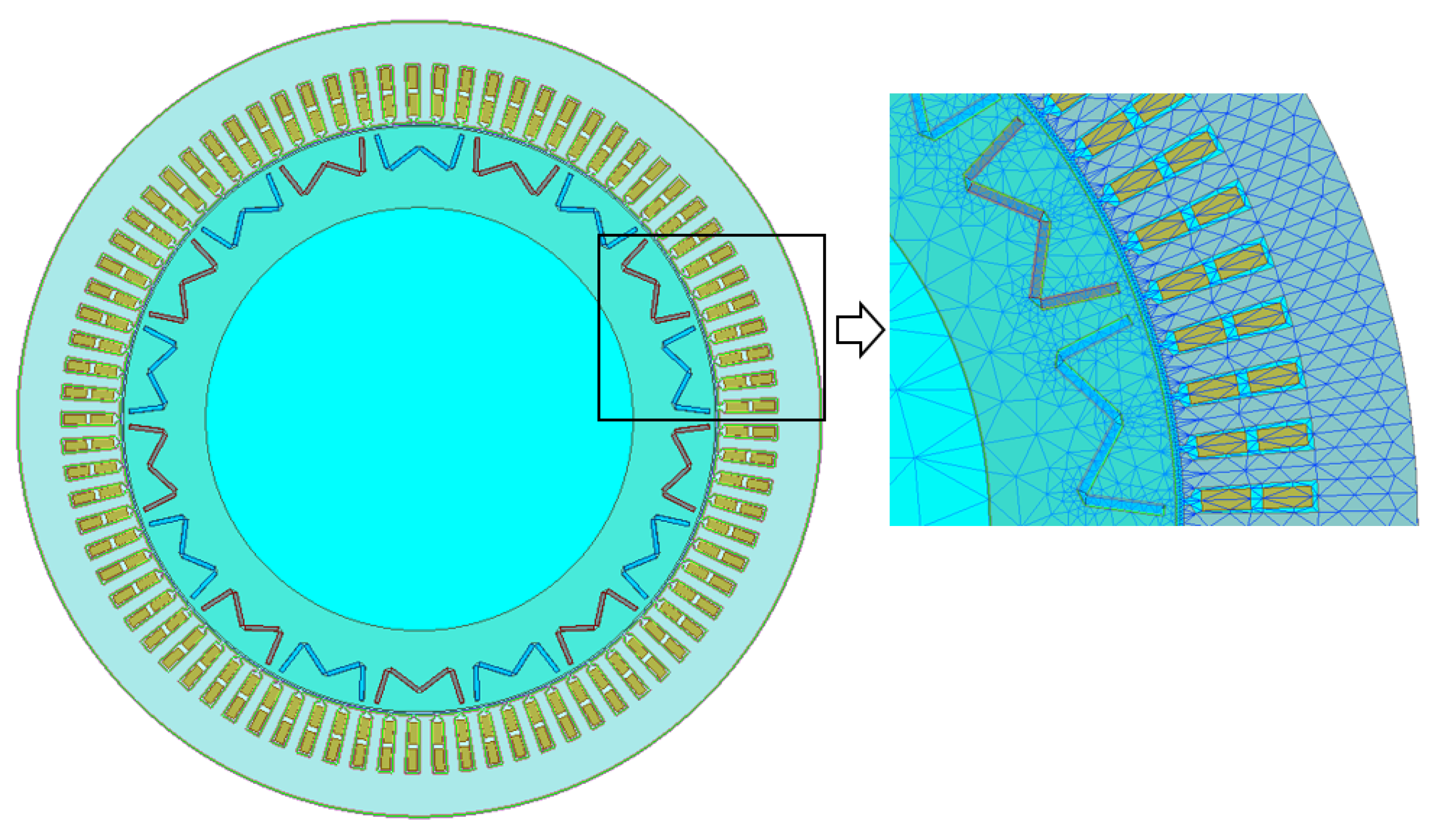
The two-dimensional generator model (
Figure 1) was developed using Ansys Electronics software (version 2023/R1), which is dedicated to finite element analysis of electromagnetic field distribution. The ratings of the generator are presented in
Table 1. The model contains nonlinear magnetization characteristics of both the stator and rotor cores, accounts for rotor motion, includes permanent magnets (type N45SH) mounted in the rotor, and features an external electrical circuit with voltage sources representing the stator winding (
Figure 2). The effects of eddy currents in the laminated cores of the stator and rotor, as well as skin effects in the stator coils, are not considered.
The studied generator possess a double-layer loop stator winding the same as that used in high-power electrical machines.
Table 2 presents the main dimensions and winding data of the studied generator.
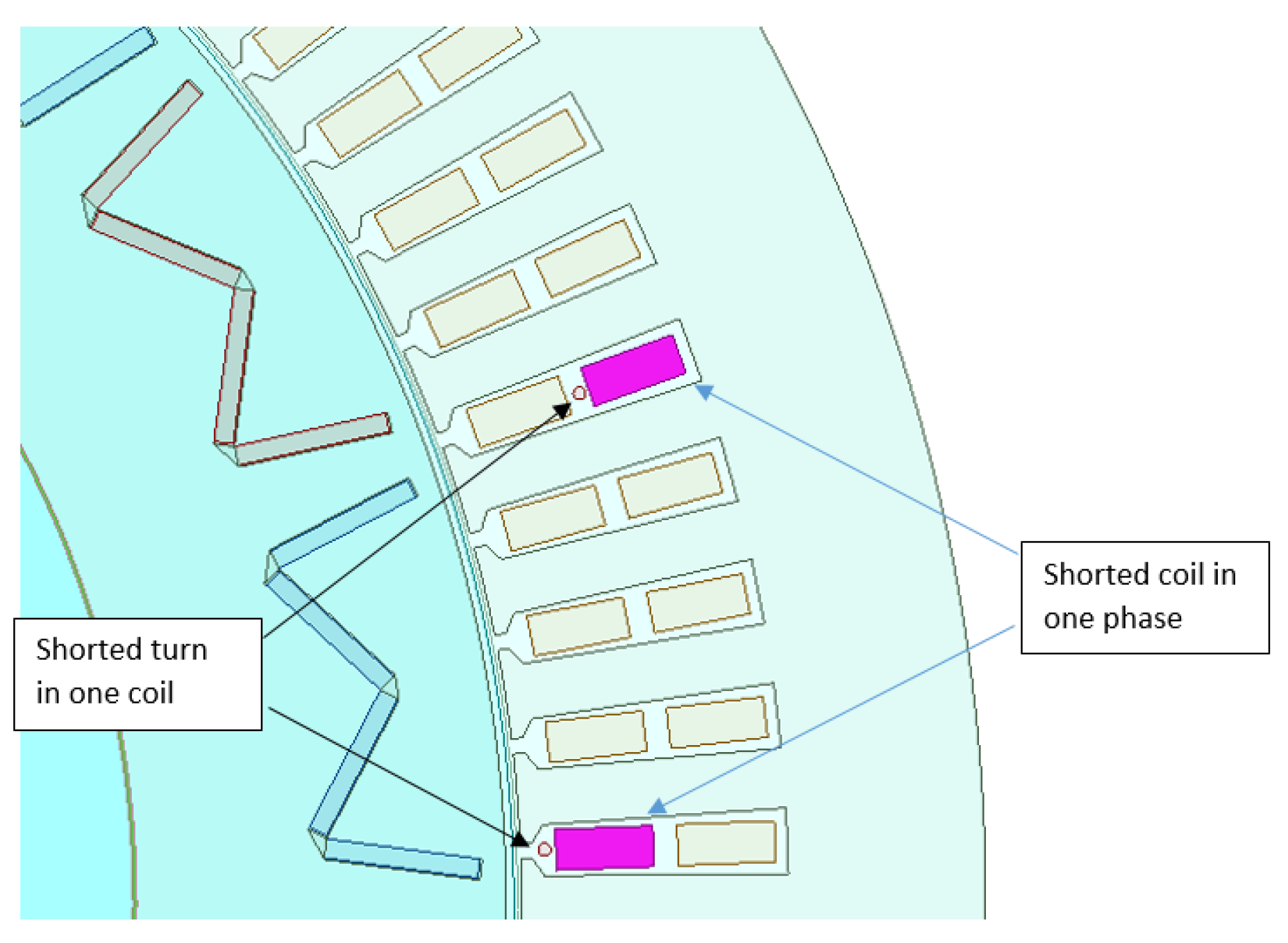
From phase A of the stator winding, elements corresponding to the turns shorted on the end-winding part are separated in the field model (
Figure 3) and the circuit model (
Figure 2). The separated fragment also contains resistances and inductances of both end-winding parts of the shorted turns. In the remaining part of the phase winding, both the straight parts of the winding and end-winding part have summary representations. The different models are used to simulate short circuit of the entire coil and chosen turns. In this case, all the phase winding coils together with their end-winding connections are represented in the circuit model. In both models, short circuit is realized using the time-controlled switch. This switch is a resistor that has a very low resistance in the on state and a very high resistance in the off state. In the calculations performed for such a situation, it is assumed that the value of the on-state resistance is 10
−6 Ω.
3. Analysis of Inter-Turn Short-Circuit Fault at Rated Frequency
The experimental studies on inter-turn short circuits using the real and field–circuit models of a squirrel cage induction motor showed very accurate convergence of the results [
5]. The conclusions obtained allow us to assume that in the case of research on PMSGs, a similar convergence of results will be obtained. Therefore, the field–circuit model of a PMSG with a two-layer stator winding with a number of parallel branches equal to three is analyzed. In the case of a winding filled with a winding wire, the arrangement of individual turns in the slot is random (this is particularly visible in manual prototype production). Hence, turn short circuits can be random. Four cases of short circuits were analyzed: 1-turn, 4-turn, 10-turn and the entire coil. In all cases, the short circuit occurs during operation of a nominally loaded generator at rated speed and supplied with a symmetrical and sinusoidal three-phase voltage system. The short circuits appear in phase A and the first branch (
Figure 2) and occur at 1.3 s of the simulation. Separate simulations are performed for speeds lower than the rated speed to observe whether they had an impact on the indicated diagnostic patterns. In all analyzed cases, the temperature of the stator winding and permanent magnets was 95 °C and 60 °C, respectively.
The following subsections present potential diagnostic patterns that can be used for early detection of inter-turn short circuits in the stator winding of PMSGs and for describing the physical phenomena existing inside the studied generator.
3.1. Back EMF
The number of shorted turns in the stator winding has a significant effect on the back EMF value. In this abnormal condition, the magnetic induction waveform in the air gap between the stator and the rotor is distorted, contributing to the creation of higher harmonics.
Figure 4 shows the back EMF waveform for three phase-to-phase voltages in the time interval from 0 to 0.02 s. The back EMF voltage amplitudes A-B and C-A decrease with the increase in the number of shorted turns. However, there is no significant decrease for the B-C voltage. The difference in the values of these voltages can be used to diagnose the occurrence of shorted turns.
Figure 5 presets the distribution of these voltages into higher harmonics. The total harmonic distortion (THD) of the studied healthy generator equals 0.61%. The THD coefficient strongly depends on number of shorted turns (
Figure 6). The THD coefficient increased the most for phase B-C, i.e., between phases in which no turn short circuits occurred.
3.2. Short-Circuit Current
At the first moment of a short-circuit occurrence, an unsteady state is present. The establishment of short-circuit current waveform depends on the number of shorted turns. The higher the value, the longer the time constant (
Figure 7). The value of the current flowing through the short-circuited path is highly dependent on both the number of affected turns and their electrical resistance. The smaller the number of shorted turns, the higher the current. For the analyzed generator, the short-circuit current exceeds 7
ISN.
Short-circuit current is strongly distorted compared to the stator current of the healthy generator. In all analyzed cases, a third higher harmonic appears (
Figure 8). The percentage value of the third higher harmonic is in the range of 10.5–11.5% with respect to the first harmonic of the short-circuit current.
3.3. Stator Currents
Supplying the stator winding with rated voltage and frequency causes ripples in the stator current waveform, because the generator does not have a damping cage in the rotor. The lack of a converter system allows for eliminating the influence of control on the stator current waveform and thus on its higher harmonics. Thanks to this, the determined higher harmonics arise only from electromagnetic phenomena occurring inside the studied machine. The occurrence of shorted turns does not affect the ripple period (
Figure 9). Only current peaks appear in phase B. The more shorted turns there are, the larger the current peaks. The occurrence of shorted turns increases most of the higher harmonics of the stator current waveform (
Figure 10). The largest increase is noted for the second and third higher harmonics. In all phases, the second higher harmonic is high and does not change significantly with different numbers of shorted turns. On the other hand, the third higher harmonic increases with the increase in the number of shorted turns, but only for phases A and B. It is possible that this phenomenon results from the phase distribution in the slots where the shorted turns occur.
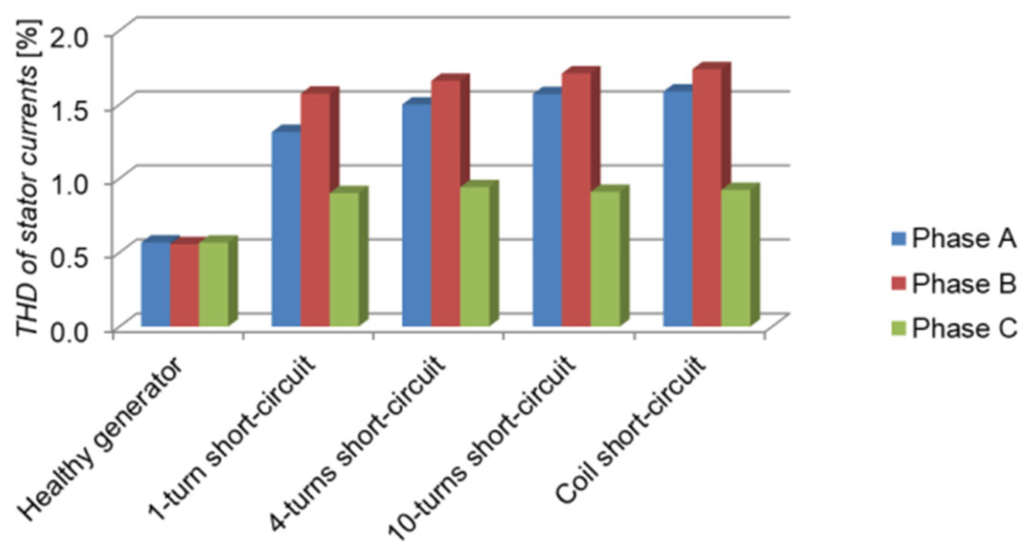
Regardless of the number of shorted turns, the THD coefficient reaches a similar value of 1.6–1.7% for the stator current in phase B (
Figure 11). In the case of phase A, the THD coefficient varies in the range of 1.3–1.6%, and for phase C it is constant and unchanging for different numbers of shorted turns and equals 0.9%.
3.4. Instantaneous Power
Instantaneous power can be used as diagnostic pattern to detect the inter-turn short circuit for induction motors and line-start permanent magnet synchronous motors (LSPMSM) [
5,
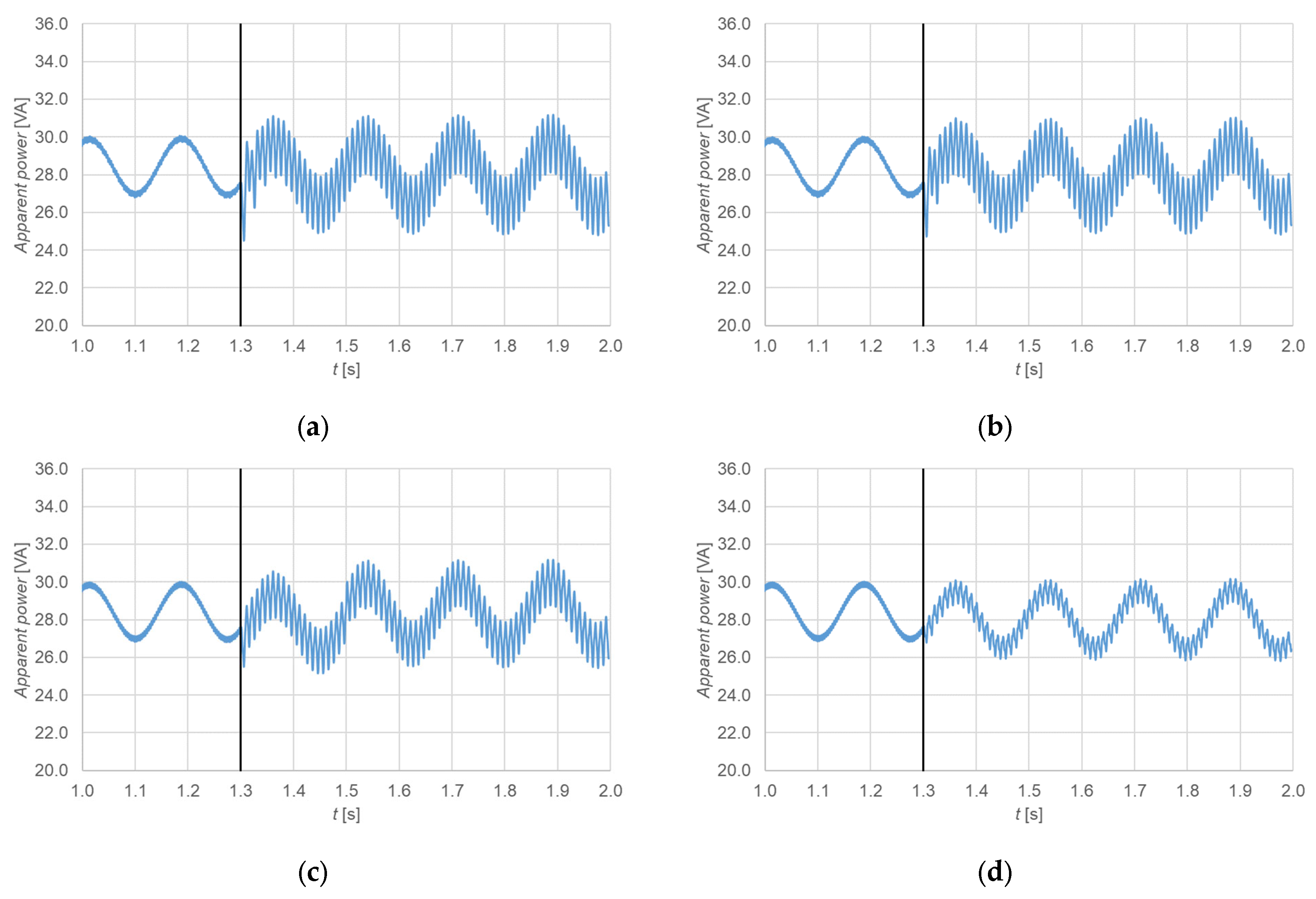
7]. The occurrence of inter-turn short circuits contributes to a sudden increase in instantaneous power. This is probably the cause of the occurrence of higher harmonics in the magnetic induction in the air gap causing the induction of eddy currents in the rotor cage. The studied generator does not have a rotor cage; moreover, the share of one coil in the balance of the entire machine (eighty-one coils) may be too small to increase the absorbed power. Therefore, this pattern cannot be used to detect inter-turn short circuits in stator winding in the PMSGs (
Figure 12). This diagnostic pattern may be more effective for machines with a lower number of poles, where the proportion of shorted turns may be larger relative to the number of series turns in the stator winding, or when a damping cage is used in the rotor.
3.5. Speed and Electromagnetic Torque
In the analyzed cases, short circuits do not affect the rotational speed fluctuations or the falling out of synchronism of the studied generator (
Figure 13). However, ripples are noted in the electromagnetic torque waveforms (
Figure 13). The number of short-circuited turns impacts the electromagnetic torque ripple. These ripples do not significantly affect the increase in machine vibrations. These fluctuations are definitely smaller than for high-speed induction machines and LSPMSM [
5,
7].
3.6. Overload
The shorted turns reduce the number of series-connected turns in the stator winding. This increases the maximum electromagnetic torque while reducing the power angle at which it occurs (
Figure 14a). However, these changes are not significant.
Figure 14b presents an enlarged view of maximum electromagnetic torque.
3.7. Cogging Torque
Cogging torque in rotating electrical machines is the torque generated by the magnetic field of permanent magnets in the currentless state of the windings. Such torque may originate from the change in the reluctance of the magnetic circuit accompanying the rotation of the rotor for the magnetomotive force of the permanent magnets. Cogging torque is an undesirable component of the torque generated by the machine and it is sought to be minimized. It is of reluctance origin. The stator tooth distribution has the greatest influence on it. Inter-turn short circuits have no influence on the size of the cogging torque (
Figure 15).
3.8. Various Load at Rated Frequency
The influence of different loads of the studied generator on the operating properties is investigated. An asymmetric distribution of stator currents is noted during inter-turn short circuits (
Figure 16). Smaller symmetry occurs in the case of a smaller number of shorted turns. The current in the phase in which the short-circuit occurs (Phase A) is smaller than the current occurring in the healthy generator in the case of low loads (up to 0.4
TN). However, in the case of high loads (from 0.5
TN), a larger current is noted in phase B in relation to the symmetrical currents in the healthy generator. Only current in phase C changes the least after the occurrence of inter-turn short circuits in the entire load range.
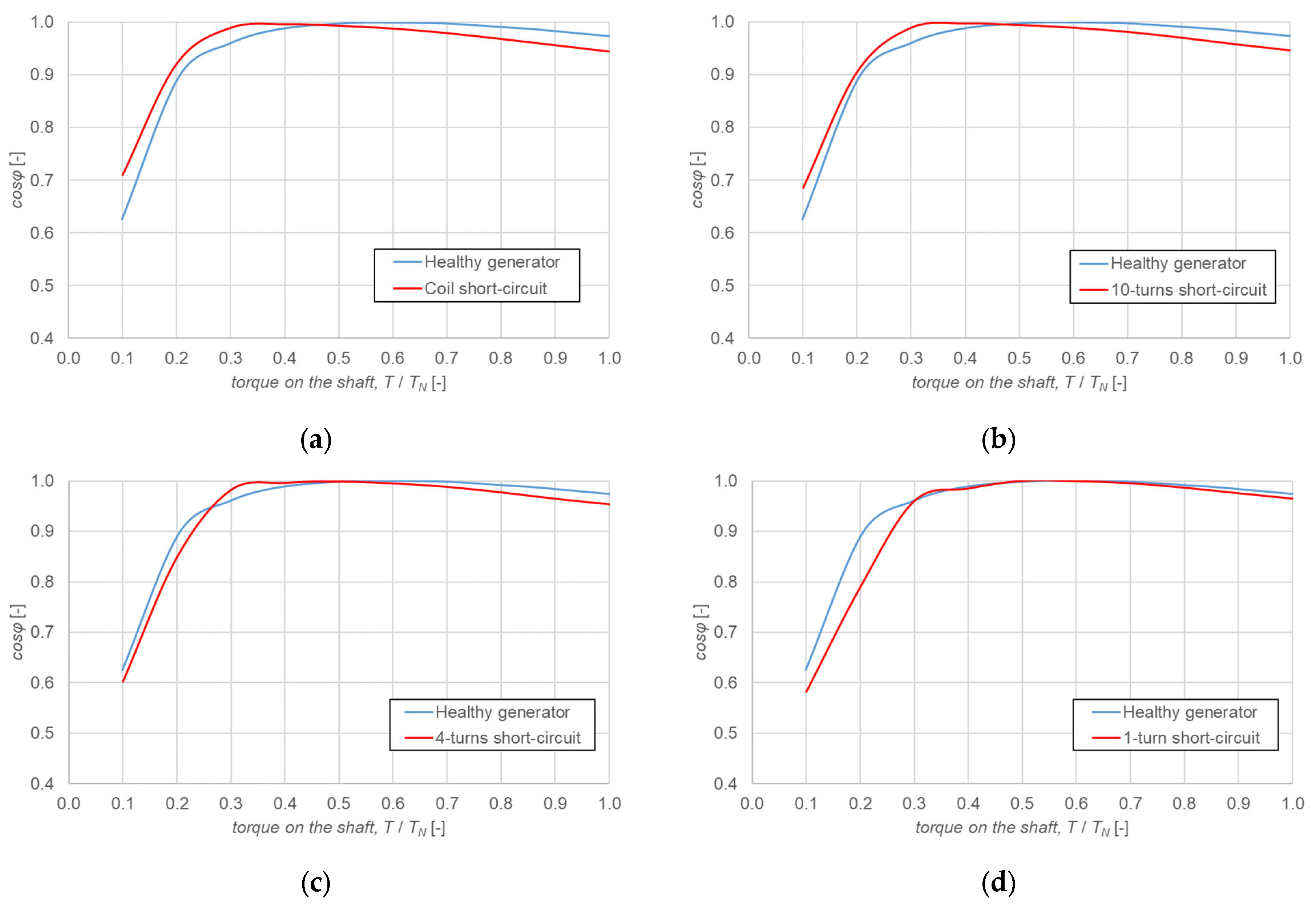
The analyzed abnormal state of the generator’s operation significantly affects the power factor values (
Figure 17). For shaft power above 0.5
TN, the value of power factor decreases. Power factor significantly decreases for higher number of shorted turns and for greater torque on the shaft. In the analyzed load range, the generator absorbs reactive power from the power system. In the case of low loads (below 0.4
TN), there is no clear trend. For a small number of shorted turns (one and four), the power factor is lower than that which occurs in a healthy generator. However, for a larger number of shorted turns, the power factor is higher than that observed before the short-circuit state and increases with the increase in the number of shorted turns (
Figure 17a,b). In this state, reactive power is generated to the power system.
3.9. Stator Current Hodograph
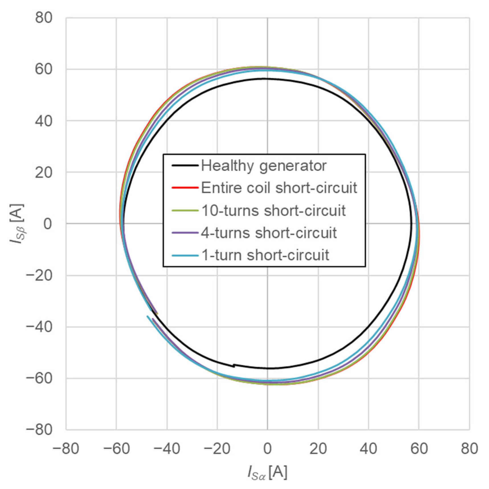
To determine the effect of stator winding asymmetry on stator currents, one can use the changes in the current vector hodograph in the stationary coordinate system α–β, described by the components of the stator current space vector (3) and (4).
In a symmetrical winding of an electric machine, the determined stator current vector hodograph has the shape of a circle. Damage to the stator windings causes deformation of the hodograph, which changes from a circle to an ellipse with increasing damage degree. Additionally, short circuits cause a different direction of deformation (change in the orientation of the main axes of the current hodograph), depending on the stator winding phase in which the damage occurred. It is therefore possible to determine the extent of stator winding damage based on the degree of deformation of the current vector hodograph, as well as to precisely locate in which stator phase the short-circuit occurred.
Inter-turn short circuits in the studied generator deform the hodograph. Short-circuiting of just one turn changes the hodograph from a circle to an ellipse. The analyzed abnormal operating states significantly affect the shape of the hodograph. The resulting ellipse deflects correctly (
Figure 18, quarters I and III), because this indicates damage in phase A.
3.10. Flux Lines and Magnetic Induction
Figure 19a shows the distribution of flux lines and
Figure 19b presents the distribution of magnetic induction of the healthy generator during rated load. During inter-turn short circuit, the magnetic field is weakened, especially in proximity to the place where the short occurs (
Figure 20). The analyzed abnormal condition affects the increase in the saturation of the magnetic circuit, especially in the tooth part located close to the shorted turns (
Figure 21). The increase in iron losses is negligible. For comparison, iron losses for a healthy generator equal 540 W, while with a shorted entire coil they increase by only 6 W. From the circumferential distribution of the normal component of the induction in the air gap, it can be seen that inter-turn short circuit only affects the pole where the short circuit occurred (
Figure 22a,b as enlarged view). The magnetic induction decreases only in the pole with an angular spread between 7 and 27 degrees.
4. Analysis of Inter-Turn Short-Circuit Fault at Various Frequencies
The studied generator is tested for different supply frequencies to check their effect on higher harmonics of the stator current. For this purpose, the generator is supplied with voltage resulting from the relationship
U/
f = const. The driving torque on the shaft is
TN. Two frequencies of 40 and 30 Hz are analyzed.
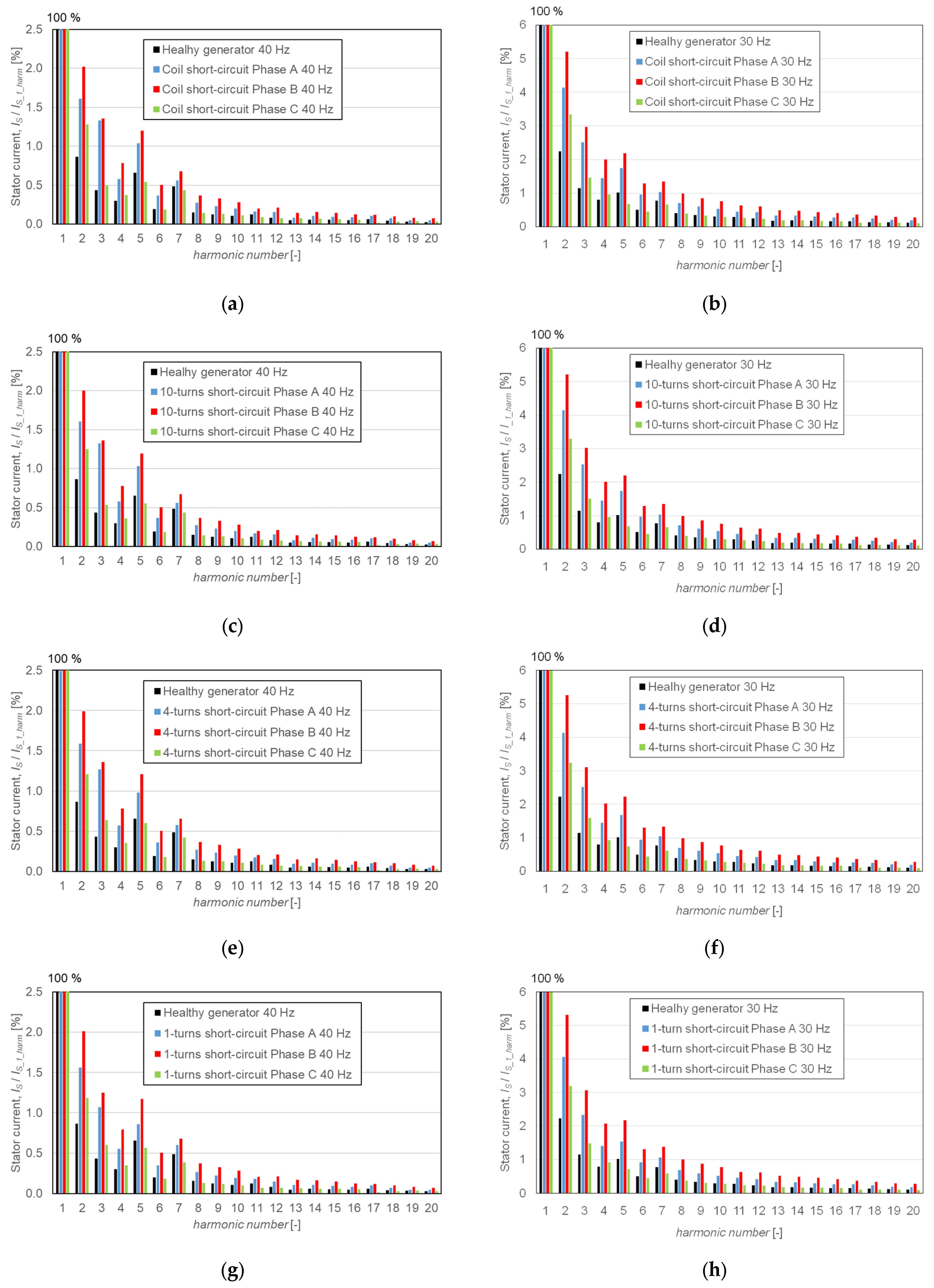
Figure 23 shows the distribution of stator phase currents into higher harmonics for different short circuits. The results clearly show that the lower the frequency, the higher the harmonics increase, both in the healthy generator and with inter-turn short circuits. The highest harmonics increases occur in the second, third, fifth and seventh orders. The higher fifth and seventh harmonics of the stator current depend on the designed electromagnetic circuit of the studied generator. In addition, their values can change due to changes in load (power angle). This is mainly due to changes in the rotor position in the
d and
q axes. The presented results show that inter-turn short circuits significantly affect the distribution of the electromagnetic field and changes in reluctance in the magnetic flux path. This is particularly visible at low frequencies (
Figure 23). Therefore, from the point of view of diagnosing inter-turn short circuits in the stator winding, second- and third-order harmonics are important, including their multiples.
Regardless of the supply frequency, inter-turn short circuit increases the second and third higher components of the stator current. There are differences in the values of these higher harmonics in the individual phases. Regardless of the number of shorted turns, the values of the second higher harmonics are at almost the same level (
Table 3). The same situation exists in case of third higher harmonics (
Table 4). The lower the supply frequency, the higher the harmonic values.
Different values of supply frequency do not have a significant influence on the values of higher harmonics in the short-circuit current during short circuit of turns. The third higher harmonic increases the most (
Figure 24). There are differences between the individual phases, but the percentage share of the third higher harmonic varies in the range of 10 to 12%, regardless of the number of short-circuited turns.
5. Discussion and Conclusions
This article presents the results of numerical simulations of inter-turn short circuits in the stator winding of a permanent magnet synchronous generator dedicated for use in small and medium-sized hydroelectric and wind power plants. The simulations were performed for both a fault-free generator and one affected by faults involving 1, 4, 10, and 14 shorted turns, as well as a scenario with a fully short-circuited coil, under various operating conditions. The results indicate that the magnetic field distribution and operating characteristics of the generator are significantly affected by the increasing number of shorted turns. The analysis also revealed the presence of a third harmonic component in the short-circuit current during an inter-turn fault. The value of this harmonic in relation to the first harmonic is at a similar level regardless of the number of short-circuited turns.
Instantaneous power cannot be utilized to detect inter-turn short circuits, because it does not change its value substantially, as in the case of induction machines and LSPMSMs.
Back EMF values and stator current hodographs can be utilized as the patterns for detecting inter-turn short circuits in low-speed PMSGs if they are set to the appropriate sensitivity. The share of several turns or even the entire coil does not constitute a large share in the number of turns connected in series in the tested generator and therefore they do not have a large effect on the back EMF values. However, they significantly affect the THD coefficient. The stator current hodograph does not create such a clearly defined ellipse as in the case of high-speed machines, in which the phenomenon under investigation occurred. In case of measurement disturbances (noises), it can lead to incorrect transformations and, consequently, to unjustified disconnection of the generator from the power system.
The diagnostic pattern for detecting inter-turn short circuits in stator winding in low-speed PMSGs may be the second and third higher harmonics of the stator current phase waveforms and/or their multiples. The fifth and seventh higher harmonics can also be used. In the analyzed PMSG, these harmonics are much higher for a healthy stator winding, and the difference between a healthy generator and one with shorted turns is not as significant as in the case of the second and third higher harmonics.
In the analyzed generator, phase B showed the greatest variability, not phase A, where the short circuit occurred. It was noted that with decreasing supply frequency, the share of higher harmonics during the short circuit increases, which makes it much easier to diagnose generator damage.


