Article

Climbing the Pyramid: From Regional to Local Assessments of CO2 Storage Capacities in Deep Saline Aquifers of the Drava Basin, Pannonian Basin System

1
University of Zagreb, Faculty of Mining, Geology and Petroleum Engineering, Pierottijeva 6, 10000 Zagreb, Croatia
2
Croatian Geological Survey, Department of Geology, Sachsova 2, 10000 Zagreb, Croatia
*
Author to whom correspondence should be addressed.
Energies 2025, 18(14), 3800; https://doi.org/10.3390/en18143800
Submission received: 13 June 2025 / Revised: 7 July 2025 / Accepted: 14 July 2025 / Published: 17 July 2025
(This article belongs to the Collection Feature Papers in Carbon Capture, Utilization, and Storage)

Abstract

Deep saline aquifers in the eastern part of Drava Basin were screened for potential storage sites. The input dataset included three seismic volumes, a rather extensive set of old seismic sections and 71 wells. Out of all identified potential storage objects, only two sites were found to be situated in the favorable geological settings, meaning that the inspected wells drilled through structural traps had a seal at least 20 m thick which was intersected by only a few faults with rather limited displacement. Many more closed structures in the area were tested by exploration wells, but in all other wells, various problems were encountered, including inadequate reservoir properties, inadequate seal or inadequate depth of the identified trap. Analysis was highly affected by the insufficient quality and spatial distribution of the seismic input data, as well as in places with insufficient quality of input well datasets. An initial characterization of identified storage sites was performed, and their attributes were compared, with potential storage object B recognized as the one that should be further developed. However, given the depth and increased geothermal gradient of the potential storage object B, it is possible that it will be developed as a geothermal reservoir, and this brings forward the problem of concurrent subsurface use.

1. Introduction

Over the past two decades, it has become increasingly apparent that the exploitation of fossil fuels not only faces limitations due to limited reserves and unequal distribution worldwide but also poses significant adverse impacts on Earth’s climate. Namely, the combustion of fossil fuels generates large emissions of anthropogenic carbon dioxide (CO2) from both stationary and non-stationary sources, thereby exacerbating global climate change [1]. Even if dependency on fossil fuels is diminished by transition to renewable energy sources, significant parts of cogeneration plants as well as some industrial operations (cement production, steel mills, etc.) will still need fossil fuels. It is therefore necessary to make use of the geological storage of carbon dioxide, a technology that provides a permanent solution for reducing the amount of carbon dioxide emitted into the atmosphere [2].
Large-scale deployment of Carbon Capture and Storage (CCS) will require a large number of storage sites. Site screening is necessary to focus efforts on the most promising sites [3,4,5,6,7]. So far, many site screening methods have been developed [6,8,9]. The site screening conducted as part of the GEODEP project, presented in this work, aimed to advance the evaluation of CO2 storage potential in the study area and used tailored screening criteria to obtain that goal. More specifically, this work explores whether the available regional vintage dataset, excluding areas under existing exploitation licenses, can be utilized to more accurately estimate key parameters for screening previously drilled structures.
In the eastern part of Drava Basin, several large point sources emit more than 50 kt of CO2 per year, including the Našice cement plant, Belišće paper mill, Osijek cogeneration power plant, and the furniture factory in Đakovo. Table 1 presents the CO2 emissions recorded in the Environmental Pollution Register (https://roo.azo.hr/, accessed on 7 January 2025) for the 2020–2023 period. While the Našice cement plant and Belišće paper mill exhibited relatively stable emissions, fluctuating within approximately 10%, the Osijek cogeneration power plant demonstrated greater variability, with a noticeable decline in 2022 and 2023.
The Našice cement plant is particularly promising as a carbon capture facility due to its high CO2 emissions. Although the nearly depleted reservoirs of the Bokšić gas field are considered the primary storage site for this source, alternative storage possibilities should also be explored.
Two deep saline aquifers (DSAs)—Drava and Osijek—were defined in Drava Basin and assessed within the EU GeoCapacity project [10]. The eastern part of the DSA in Drava and whole DSA in Osijek are situated within the study area, as seen in Figure 1. While the DSA in Drava was delineated using regional maps depicting the thickness of Upper Miocene sandstones and cross-sections illustrating the depth of sandstone layers and cap-rock thickness [11,12], the boundaries and characteristics of the DSA in Osijek were updated based on the more recent study [13]. The petrophysical characteristics of the DSA Drava were approximated by limited data from [11,12] and regional estimates from [14]. Similar values were employed for the DSA Osijek. The lateral continuity of the cap rocks was assumed based on regional cross-sections; it was only partially verified through well log interpretation for the DSA Osijek [13], but not for the DSA Drava. The relative permeability of the cap rocks for CO2 remained unassessed; thus, their efficacy as CO2 isolators could not be established.
There were altogether eight nearly depleted hydrocarbon fields that were identified as potential storage objects in the Drava Basin, but only two of them—Beničanci and Bokšić—were situated within the study area. Their total storage potential was estimated to be 22.4 Mt [15]. Vulin et al. [15] assumed that the Beničanci field could be a suitable candidate for a CO2-EOR project and modeled injection volumes for the period 2025–2040. Based on the results of that preliminary study, and considering that the INA company, which operates in the Beničanci field, already runs two CO2-EOR projects in the Sava Basin [16], the development of a CO2-EOR operation at Beničanci field is a reasonable expectation. Moreover, converting depleted hydrocarbon fields into CO2 storage sites is likely to be in the company’s interest, given that the INA is among the 44 oil and gas producers obligated to contribute to the development of 50 Mt/year of operational CO2 injection capacity to meet the EU’s 2030 emission reduction target (European Commission Decision C(2025) 3222 of 22 May 2025). The INA’s individual obligation amounts to 1150 kt/year of operational CO2 injection capacity by 2030.
Considering that all climate projections require substantial reductions in CO2 emissions by 2050, stemming not solely from the transition to renewable energy sources but also from the significant implementation of carbon capture and geological storage technology, it is obvious that an intensification of technology deployment is required. This is largely related to “climbing the CO2 storage capacity assessment pyramid”. That framework served as the motivation behind reevaluating the previous CO2 storage assessments by conducting site screening within the study area.
It should be noted that while this assessment was limited to geological considerations, the next steps in research and development will be largely controlled by social factors, both economic and legal. In that sense, the problem of concurrent subsurface use, as described by [17], will surely play a major role in the planning of future activities focused on subsurface use in the study area.

2. Geological Setting of the Study Area and Potential “Storage Plays”

The studied part of continental Croatia has remarkably complex geological settings with a variety of rock types, as illustrated in Figure 2. There are three major stratigraphic units, as defined by outcrops and in the subsurface. The first unit consists of the crystalline basement (usually called “Basement rocks”), primarily composed of partially metamorphosed Paleozoic magmatic rocks—granites, granitoids, gneisses, and amphibolites—with a smaller presence of metamorphosed sediments such as schists and phyllites [18]. The second unit is characterized by Mesozoic carbonates, which are referred to as “Base Tertiary” rocks [19]. The third unit includes Neogene and Quaternary sediments that make up the basin infill [19,20].
The area experienced continental rifting from the Ottnangian to the Badenian periods, with the NNE-SSW extension which could be mostly assigned to asymmetric extensional mechanisms related to extensional detachment or low-angle faults [21]. During the Ottnangian and Karpatian periods, sedimentation was predominantly characterized by coarse-grained clastics deposited in alluvial environments [19,22], with occasional pyroclastics resulting from syn-sedimentary volcanism typical of the initial rift phase [23].
A marine transgression in the Middle Badenian [24] caused a shift from lacustrine to marine environments [25], which were marked by the deposition of thick marl layers interspersed with coarse-grained clastic sediments transported into the basin by gravity flows [24,26]. The Sarmatian period was characterized by the isolation of this “new” sea—the Paratethys from the open sea—which led to decreased salinity and contributed to a regional extinction event.
During the Pannonian stage, the region experienced further structural deformation, with the Pannonian Basin being isolated from the Central Paratethys, leading to a transition of sedimentation conditions from marine to lacustrine [27,28,29]. Significant sediment supply without a corresponding increase in accommodation space led to further transition of sedimentation environments from lacustrine to deltaic. This process eventually led to the basin’s infilling [29]. Neotectonic activity in the Pliocene and Quaternary resulted in compression and dextral transcurrent displacements, filling the remnants of Lake Pannon with coarse clastic sediments, clays, and coals. The Pleistocene glacial periods were characterized by the deposition of loess deposits and aeolian sands, while interglacial periods were marked by lacustrine, alluvial, and marsh sedimentation [30].
When considering the geological evolution of the study area, several potential “CO2 storage plays” can be identified. They actually correspond to similar settings in which hydrocarbon reservoirs were discovered within the basin area. As previously mentioned, the regional DSAs in Drava and Osijek were identified in the study area [15,31], both comprising post-rift Pannonian sandstones, which represent the only “play” assessed thus far. These sandstones were deposited both in environments of prograding deltas and as turbidites characteristic for deeper parts of Lake Pannon [19,29,32,33,34,35]. They are overlain by Pannonian marls acting as seals (see Figure 2). The second “play” would be the syn-rift coarse-grained clastic sediments of the Middle (Badenian) and Early Miocene (Karpatian), mainly represented by clinoform bodies of carbonate rockfall and debris breccias formed by the accumulation of carbonate detritus along tectonized Mesozoic carbonate slopes and cliffs and primarily onshore and partially below sea level [36], as well as coarse-grained clastic sediments deposited in sedimentary environments that include alluvial fans, fan deltas, and submarine fan bodies [21,37]. Seals for these reservoirs are marls and calcitic marls that were rather frequent in the Middle Miocene (Badenian) (see Figure 2). These Lower Miocene reservoirs are expected to be more problematic for characterization both in terms of geometry and their petrophysical properties due to their limited lateral distribution and the fact that these sedimentary bodies are dominantly characterized by dual porosity [38]. The last two plays are not associated with Pannonian Basin infill but are older rock complexes. The third “play” is represented by Mesozoic carbonates below Base Neogene unconformity, which are mostly heavily tectonically deformed [39]. The last “play” is comprised of the weathered crystalline complex beneath the Basement unconformity primarily in paleo relief highs. The seal rocks for both of these reservoir rock types are Lower Miocene fine-grained sediments.
Figure 2. Schematic geological column with marked intervals indicating reservoir and sealing properties, as well as main tectonic phases (modified after [20,25]).
Energies 18 03800 g002
It should be noted that in the Eastern part of the Drava Basin, the most important hydrocarbon reservoirs are found in the Middle Miocene breccias of the Beničanci oil field, and they have excellent petrophysical properties [19,39]. According to [36], reservoir rocks of the Beničanci field are rockfall and debris-flow breccias formed by the accumulation of significant quantities of dolomite detritus from the shore. Similar reservoir rocks, only with less favorable petrophysical properties, are found in the Kućanci-Kapelna and Bokšić-Klokočevci oil fields, as well as in the Obod and Števkovica oil fields [14]. The differences in the quality of the reservoir rocks in contrast to the rock bodies drilled through at Beničanci is due to the different paleogeomorphology of the sedimentary environment and resultant facies [36].

3. Materials and Methods

The input dataset consisted of three-dimensional (3D) seismic volumes, a rather extensive set of seismic sections and 71 wells overall that were drilled primarily from the 1970s to 1990s as part of oil and gas exploration. The 3D seismic volumes marked with numbers 1 to 3 on Figure 1 cover areas of 215.7 km2, 31.3 km2, and 254.8 km2, respectively. Seismic sections varied both in their lengths as well as in their qualities, since they were surveyed during different seismic acquisition campaigns.
The process of site screening involved inspection of seismic data in areas of 71 exploration wells in order to identify the structural or stratigraphic traps as potential storage sites. The screening criteria were selected based on [6,8,9] and slightly modified to reflect the conditions in the Croatian part of the Pannonian Basin (Table 2).

3.1. Depth Criterion

A shallower boundary of 750 m was selected mainly based on pressure requirements for obtaining supercritical state of CO2 (pore pressure > 7.4 MPa), ensuring that the available space would be better utilized and the buoyant force would decrease due to the decreased difference in density between carbon dioxide and water [40,41]. It is also expected that at greater depths, aquifers contain higher concentrations of dissolved solids and are thus unlikely to serve as sources of drinking or agricultural water [41]. A deeper depth boundary of 2500 m was chosen mainly because with greater depth come higher investments and technical challenges during implementation; carbon dioxide on the surface needs to be compressed under high pressure due to significantly higher reservoir pressures [8]. Additionally, [42] suggests that at greater depths (typically below 2400 m), increased pressure causes changes in wettability of rocks, from water-wet to CO2-wet, possibly having considerable effect on efficacy of seal rocks.

3.2. Effective Thickness and Porosity Criteria

These two parameters obviously influence the capacity of the storage site. The values set as limiting for those criteria reflect the geological settings in Croatian part of Pannonian Basin System, where the majority of gas and gas condensate fields were classified as small and medium [43]. Most of the hydrocarbon reservoirs were found to have average effective thickness values between 5 and 10 m, with only few largest reservoirs having considerable effective thicknesses values, for example, Beničanci breccias reservoir rocks in Beničanci oil field were found to have an average effective thickness of 74.3 m [14].
Regarding the porosity values, the greatest gas fields in the western part of Drava Basin (area not covered by this study) were found in fractured basement rocks with low porosity, with the average porosity having a value of 7.6% in the Molve field and even lower in the Kalinovac and Stari Gradac fields [44]. However, higher porosity values are expected in reservoir rocks with primary (Upper Miocene sandstones) and dual porosity (coarse-grained Middle Miocene clastic sediments), so limiting porosity value was set to 15% for clastic sediments and 3% for reservoir rocks with secondary porosity.

3.3. Near Wellbore Permeability

Permeability is an important parameter because it controls the injectivity, which measures how easily the fluid can be injected into a reservoir per unit thickness of the reservoir [5], so it defines not only the injection rate but also the ability of CO2 to migrate from the injection well into the permeable reservoir rock [45]. However, the parameter that would enable better assessment of injectivity is fluid mobility ratio (M), representing the ratio of mobility of the displacing fluid λD divided by the mobility of the displaced fluid λd through the following expression: M = λD/λd [46]. Since mobility is defined as product of reservoir rock relative permeability for a fluid (kw, kCO2) and fluid viscosity (μw, μCO2), it is obvious that without relative permeabilities, it is impossible to estimate this parameter. But, as Kovscek [5] emphasized, viscosity value of CO2 in reservoir p, T conditions (at 15 MPa, 47 °C) is estimated at 0.07 Pas, while water has significantly higher viscosity of 0.68 Pas. On the other hand, [47] suggested that low viscosity of CO2 does not always guarantee high injectivity. This issue is partly addressed by the study of [48], where their work suggested that the migration of the pressure wave resulting from injection of fluid into the reservoir is in fact controlled by the intrinsic permeability of the formation and the bulk compressibility of the reservoir fluid and formation. So, the permeability of reservoir rock is still regarded as an important parameter for qualitatively estimating injectivity.
Permeability values, both the one set as positive indicator as well as those set as limiting factor, are rather low. The values are reflecting the properties of reservoir rocks in Croatian part of Pannonian Basin System [43].

3.4. Reservoir Structure Criterion

A reservoir structure criterion is established based on the fact that vertical and lateral changes in lithofacies are important, since they represent changes of petrophysical properties (porosity, permeability, and capillary pressure) that will influence the migration of CO2 plume through the reservoir. On the basis of experiments and simulation results of supercritical CO2 (SC-CO2) migration through the sandstone sample with multiple clay interlayers, [49] concluded that porosity distribution and geometry of the clay interlayers significantly impact migration of SC-CO2 through the sample, with porosity showing positive correlation with SC-CO2 saturation after drainage processes.

3.5. Seal Lithology and Thickness

In the study area, it is expected that the seals are siliciclastic and act as capillary seals, where interfacial tension forces between the CO2 and water prevent CO2 from entering the water-wet phase [50,51]. The breakthrough pressure of the cap rock equals the pressure that is needed to establish a connected filament of CO2 naturally through the largest water-wet pore throats [52]. Seal lithology is thus proposed with respect to capillary pressure; fine-grained clastic sediments are expected to have higher capillary pressures due to geometry and size of their pore throats. That is why only fine-grained sediments, in the study area mostly represented by marlites or calcitic marlites, were considered effective seals, while fine-grained sediments containing larger grains, such as sandy marlites, were not taken into consideration.
Thickness of the seal is one of the factors influencing its capacity [53], which is relatively easy to estimate, since it does not demand a series of laboratory analyses like assessment of capillary pressure or relative permeability. Namely, thickness of a seal is important in a case that pressure exerted by the column of CO2 exceeds seal entry pressure, i.e., in a case where a seal starts to leak, when permeability as well as the thickness of seal will play a major role controlling the dynamics of a CO2 leakage. In given geological settings, thin seals are rather usual and can be found in numerous gas reservoirs. That was the premise behind rather low threshold value of 20 m.

3.6. Seal Lateral Continuity

Lateral continuity of a seal is a key parameter that should be considered when assessing the suitability of a potential storage site, because the seal continuity is one of the parameters controlling seal capacity [54]. However, its assessment is challenging, as it is influenced by the objective and subjective uncertainties in seismic data interpretation [55]. Objective uncertainties stem not only from seismic data limitations in resolution and quality but also from uncertainties associated with depth conversion [55,56]. Subjective uncertainties are many. They arise from interpreter bias, as interpretation varies with experience, background, and time invested [55,56,57].
The resolution and quality were especially problematic in the part of the study area covered with 2D seismic (see Figure 1), which is at least four times larger than area covered by 3D seismic blocks. Even in these blocks, despite advancements in 3D seismic technology, resolution limitations continue to influence seismic interpretation. Consequently, while the interpretation within the 3D seismic coverage area is generally reliable, it remains potentially susceptible to resolution-related uncertainties, particularly in zones where the seal is relatively thin.
It should be noted that all faults could be regarded as potential pathways for CO2 migration, even though combined structural traps with faults acting as seals are known within the Croatian part of Pannonian Basin System (PBS). It would be an oversimplification to broadly categorize older faults as barriers to fluid flow and recently active faults as preferential pathways as such generalizations may overlook the complexity of fault-related permeability. Since this was still a regional study, complex fault analyses were not performed.

3.7. Pore Water Salinity

Least attention was given to fluid properties not because it was considered to be less important but due to the scarce data available. Attention should be given to water mineralization assessments, as it is important primarily from the aspect of concurrent utilization, i.e., possibility to use identified storage objects as geothermal reservoirs. It was long ago proposed [58] that CO2 storage operations should be limited to saline aquifers whose water has increased salinity and therefore could not be considered for surface use, such as for agricultural purposes, livestock, or even as industrial water. Water with a TDS above 1500 to 2600 mg/L is not regarded as suitable for irrigation use on crops with a low or medium salt tolerance [59] that are most likely to be cultivated in the study area. When considering water use for livestock, a TDS value of 10,000 mg/L can be considered the upper limit, while most species tolerate water with mineralization of 7000 mg/L TDS [60,61].

3.8. CO2–Brine Interfacial Tension Criterion

Capillary pressure is directly proportional to the surface tension between the two fluids in contact—the higher the surface tension, the more effective the seal. The measurements of brine–CO2 interfacial tension were not conducted in this study, but numerous studies have investigated the surface tension between carbon dioxide and water/brine. Interfacial tension itself depends on temperature, pressure, and the salinity of the pore water. Experimental measurements under various pressure, temperature, and salinity conditions were conducted by [62]. Similarly, Chiquet et al. [63] performed measurements under reservoir temperature and pressure conditions, but these were with only one brine salinity of 20 g/L NaCl water. A comprehensive dataset on interfacial tension changes across different temperatures, pressures, and salinity levels was provided by [64]. Their measurements focused on a two-phase CO2–NaCl aqueous solution system, examining temperatures of 27 °C, 71 °C, and 100 °C and salinities of 5 g/L, 50 g/L, 100 g/L, and 150 g/L NaCl, with pressures ranging from 4.5 to 25.5 MPa. The resulting interfacial tension values between CO2 and high-salinity water varied between 24.78 and 46.77 mN/m, which are in agreement with the findings of [62], indicating that a general range of 25 to 50 mN/m can be considered for the interfacial tension between CO2 and pore water under reservoir conditions.
Across all studies, it was confirmed that CO2–brine interfacial tension decreases with increasing pressure under constant temperature and salinity conditions and that the effect of temperature change and salinity change on interfacial tension is much weaker than the impact of pressure change [62,64]. Given the fact that values of pore water salinity were scarce, assumptions about relative values of CO2–brine interfacial tension were made in a simple manner that higher pore pressures would be generally linked to lower CO2–brine interfacial tension.

3.9. Interpretation Workflow

In the first step, only the depth of the interpreted traps was considered. For that purpose, the data from all the wells were converted to two-way time (2T) domain, which enabled identification of structural and stratigraphic traps on seismic sections situated between 750 m and 2500 m of relative depth. Well-to-seismic tie was performed via available checkshots or vertical seismic profiling data. In the absence of either of the aforementioned, artificial neural network approach for well-to-seismic tie was used [65]. Next step included identification of reservoir intervals within the identified traps. The reservoir intervals were generally identified based on electrologs, i.e., spontaneous potential (SP) and resistivity logs (R), and their depths were confirmed and lithologies assigned based on master log and other well reports. In this first step, just general positions of reservoir intervals were registered based on normalized SP logs, but Volume of shale analyses as a way to estimate effective thickness were not performed.
In addition to the depth screening, the two most important features of the local geological setting were interpreted and used in the second phase of screening. The well was required to demonstrate the presence of a reasonably reliable cap rock, specifically, a fine-grained clastic layer at least 20 m thick. Seismic data needed to confirm the absence of major fault planes with significant displacement intersecting the planned storage complex. Seal intervals were identified using the same approach as for reservoir intervals, primarily based on SP and resistivity logs, supported by master log data. Where available, laboratory measurements of permeability conducted on core plugs further aided the assessment.
The screening then returned to reservoir rock, with its effective thickness estimated using volume of shale analysis performed based on SP log. Further on, porosity and permeability were assessed, with porosity assessment performed based on sonic log (AC). Other “porosity logs” were present only in certain intervals. In those given circumstances, permeability values were either qualitatively estimated from the pressure diagram taken during drill stem test (DST), or the results of laboratory measurements provided in well reports were used.
Site screening ended with the evaluation of fluid properties. These criteria, although undoubtedly important, were given lesser significance because the formation water analyses were rarely performed, i.e., only when successful DST enabled formation water sampling and analysis. Therefore, the formation water salinity was taken from DST reports where available.
In order to assess potential and enable comparison of chosen traps, simple capacity calculation was performed using simplified volumetric approach (modified after [66]) defined as
GCO2 = Vtrap × rCO2 × Esaline,
where GCO2 represents mass of CO2 that could be stored in potential trap, Vtrap is the volume of a trap that is calculated from geometrical parameters of the trap (top surface, presumed gas/water contact surface), rCO2 is CO2 density at assumed reservoir pressure and temperature, and Esaline is a CO2 storage efficiency factor describing a portion of a total pore volume of a trap that could be filled with CO2.
During injection operations, it is expected that the internal pore pressure increases, and therefore, the effective overburden pressure decreases [67], thus causing the mineral grains to decrease their volume, i.e., the pores to expand. Also, pore water will decrease its volume as a result of increase in effective overburden pressure. Capacity due to water and pore compressibility was calculated as follows [68]:
GcomCO2 = dVpp.i. × rCO2p.i,
dVpp.i. = Vpi × (cp + cw) × dpp,
where GcomCO2 represents capacity due to pore water compressibility (cw, in Pa−1) and pore compressibility (cp representing pore compressibility (Pa−1)), dVpp.i. represents additional pore volume post injection (m3), Vpi represents initial pore volume (m3), and dpp represents change in pore pressure due to injection (Pa).
Total CO2 storage capacity (GTCO2) is calculated by adding capacity due to pore water and pore compressibility to volumetric capacity as defined below:
GTCO2 = GTCO2 + GcomCO2,
The pore compressibility coefficient values were taken from published studies. An exception is the pore compressibility coefficient value for polymictic breccias–conglomerates, where the reported pore compressibility of the Tilje Formation, presented by [69], was adopted, with a value of 2.49 × 10⁻¹⁰ Pa−1. The fracture compressibility coefficient in schists was taken from [70], having a value of 3 × 10⁻¹² Pa−1, while pore compressibility coefficient in sandstones (cpsand in psi−1) was calculated using equation developed for consolidated sandstones according to [71]:
cpsand = (−5786.5 Φ3 + 4956.2 Φ2 − 1407.9Φ + 140.3) ∙ 10−6,
Pore water compressibility coefficients were calculated as [72]
cw =1/(7.033 ppp.i. + 541.5 CNaCl − 537 T + 403,300),
where cw is water compressibility (1/psi), ppp.i. is pore pressure post injection (psi), T is temperature (°F), and CNaCl is salinity of pore water (g NaCl/l).
It was assumed that the injection of CO2 will increase pore pressure by 30%, which aligns with suggested increase in pore pressure between 30 and 80% with respect to initial pore pressure [73].
Only one value of average density was used, estimated at medium relative depth, using the real gas equation of state [74]. Average temperature was calculated assuming linear geothermal gradient in wells drilled through the potential storage objects. The geothermal gradients were obtained based on temperature measurements taken during drill stem tests. Pore pressure was calculated assuming hydrostatic pore pressure gradient that was in alignment with the results of drill stem tests.
It should be noted that storage efficiency factor was assumed to be 10% for both potential storage objects. Higher storage efficiency factor was assumed based on the fact that the geometry of the traps is relatively well defined. The main uncertainties are related to inadequately defined porosity (a single average porosity value was used for each trap) as well as the macroscopic and microscopic displacement efficiencies, which are collectively referred to as sweep efficiency in petroleum engineering. Macroscopic displacement efficiency is closely related to the degree of heterogeneity in petrophysical properties, as well as density difference between CO2 and in situ water. Microscopic displacement efficiency is related to irreducible saturation of the reservoir rock for in situ water. Both displacement efficiencies have been studied for decades for the purpose of oil and gas production [75,76,77]. It is obviously challenging to draw conclusions about the structure and characteristics of the reservoir rocks forming the aquifer, which are necessary to define the storage efficiency factor [66]. A value of 10% was selected as representative, positioned between the product of the P10 values of volumetric displacement efficiency (Ev), microscopic displacement efficiency (Ed), and the ratio of effective to total porosity (Eφeff/φtot) for clastic reservoir rocks (3.58%) and the product of their P90 values (19.22%), as given by [66]. The selected storage efficiency factor could be regarded as optimistic, as [78] showed that in the case they presented the effective-to-total porosity had the greatest influence on the overall uncertainty in the storage efficiency factor. Moreover, [79] pointed out that the storage efficiency factor is, in fact, a meaningless parameter if the injection scheme is not taken into account.

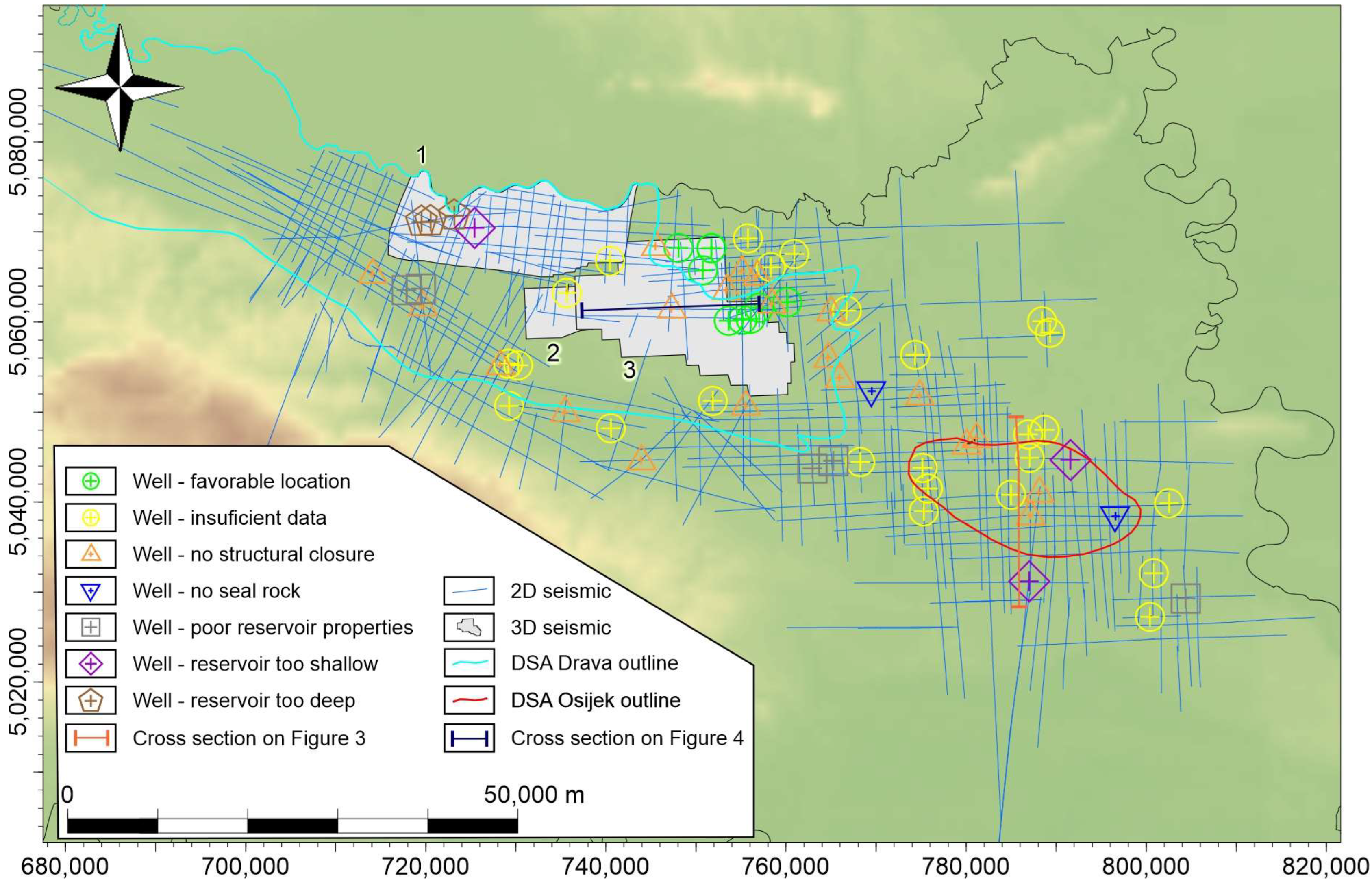
4. Results of Site Screening and Comparative Analysis of Traps Identified as Potential CO2 Storage Sites

The results of the site screening are presented in Figure 1. From the schematic lithological column given in Figure 2, it can be observed that the rocks with reservoir properties represent a great portion of subsurface in the eastern part of the Drava Basin and that they are mostly overlain by the sediments, with the lithology indicating sealing properties. In contrast, on the map in Figure 1, only two locations have been selected as the promising ones based on the overall favorable conditions. The most frequently encountered problems were related to unfavorable local geological settings—including a lack of structural trapping (example given in Figure 3); the inconvenient position of the drilled trap, i.e., the drilled trap was situated either too deep or too shallow with respect to the established depth criteria (traps located too deep or too shallow); complex structural settings (too many faults intersecting the trap); inadequacies of the seal with respect to lithology (increased amount of coarser grains within the fine grained rock) or thickness; and inadequacies of the reservoir rocks regarding their petrophysical properties. Figure 3 shows an unfavorably set well, without visible traps in the well area and possible traps toward the north and south being intersected by faults, with the basin infill showing complex structure. Normal faults intersecting the Base Neogene unconformity are predominantly associated with extensional tectonics characteristic of the Early to Middle Miocene. In contrast, faults affecting younger sedimentary units display both normal (example Figure 4) as well as reverse displacement, reflecting Quaternary basin inversion (Figure 3).
Frequently, there was more than one problem assigned to each well, as in the example of the well in (Figure 4), where anticlines in its post-rift Pannonian sediments were dissected by large faults, while the antiform beneath Rs7, the marker delineating the boundary between the syn-rift Middle Miocene and post-rift Upper Miocene sediments, was characterized as very poorly permeable based on laboratory measurements obtained from core plugs and drill stem test (DST) results.
Aside from the geological constraints, in the majority of cases, the problems were related to data coverage or quality, including the insufficiency of available seismic data to establish the structural closure, difficulty in establishing the continuity of the seal, and discrepancies between well logs and other well data necessary to establish the properties of either the reservoir rocks or the seal.
With all the mentioned considerations used as critical impediments, only the two locations were singled out and treated as the potential storage sites. From the two, one is represented by a depleted gas reservoir of a decommissioned gas field and in that sense does not represent the storage object in deep saline aquifer per se. Structural maps of the top of the potential storage objects A and B are given in Figure 5. It can be observed that the storage sites show significant differences; storage site A has a triangular-shaped antiform defined by a distinct topographic paleo relief high, while storage site B is a brachianticline elongated along an E-W strike. Storage object A could be therefore defined as a palaeogeomorphic trap, consisting of a buried hill type below “Tg” unconformity (Figure 2) and an associated compaction anticline above the “Tg” unconformity. Storage object B is a typical structural trap. The structural closure of the storage object A is considerable; its water–gas contact was estimated at −1020 m, and the top of the antiform was drilled by well A at −978 m; the well itself is located approximately in the middle of the structure. The total estimated volume of the storage site A is 32.22 × 10⁶ m3, with an estimated average porosity of 8%, while it’s pore volume was estimated to be 2.90 × 10⁶ m3. The relatively low porosity value is indicative of a complex pore structure, reflecting the combined influence of both dual and secondary porosity. The upper part of the storage object is represented by conglomeratic sandstone and breccia conglomerate having dual porosity, while the lower part below the “Tg” unconformity consists of a quartz mica schist having only secondary porosity. Several faults have been interpreted within the structure with an ESE-WNW strike. Their throws are relatively small, from a few meters for the smaller fault on the western part of the antiform to ten meters for the largest fault. Since the cap rock thickness exceeds 20 m, fluid migration through fault zones should not occur. Storage site B is characterized by a typical combination of trap types and reservoir rock. Namely, the reservoirs in the Upper Miocene sandstones in brachianticlines represent the most common type of hydrocarbon reservoirs in the Drava as well as in the Sava Basin. (For example, reservoirs of Ivanić and Žutica oil fields, where CO2-EOR operations are in progress, are represented by this type of trap and reservoir rock, as reported by [80,81]). The structural closure of storage site B with almost 70 m is significantly larger in comparison with the storage site A. The top of the structure was defined at −1652 m and was drilled by three wells. The gas–water contact, or maximal structural closure depth, was at −1720 m. The structure is intersected by three normal faults, with the eastern and western ones striking generally NE-SW and the central one having an oblique fault plane striking N-S. All faults are characterized by rather steeply inclined fault planes. The throws of the faults at the center of the structure are below five meters, while the eastern one has a throw with a maximum of twenty meters. Similarly to structure A, the interpreted faults should not have significant impacts on the sealing efficiency.
The characteristics of each trap chosen as potential CO2 storage site as well as the areas that need further research to prove the adequacy of each trap as a CO2 storage site are given in the Table 3.

5. Discussion and Conclusions

Insufficient data coverage and data quality in particular, as well as the absence of adequate traps, acted as the main limitations in the conducted screening. These factors disabled further analysis aimed to identify geological settings controlling the storage potential.
Aside from the mentioned “Beničanci breče” facies in the Beničanci oil field with fair porosity and permeability [36], syn-rift sediments in the hydrocarbon fields Kućanci-Kapelna, Bokšić-Klokočevci, and Obod-Lacići [36] situated within the study area are characterized by lower values of permeability [14]. Good reservoir properties were found in the Badenian calcarenites. In contrast, DST measurements performed on syn-rift coarse clastic sediments indicate poor reservoir properties. This was observed in all four wells marked as having poor reservoir rocks on the map in Figure 1, as well as in other wells where this was not the primary disqualifying factor.
Regarding the lower depth limit, this is the most arguable factor applied during the site screening process, since it is mostly defined by some non-geological criteria—including the compression of CO2 to higher pressures as a potential economic cutoff.
The total CO2 storage capacity estimated for the two presented storage objects amounted to 1.35 Mt and represents a significantly lower estimate compared to previously reported CO2 storage capacity of approximately 1187 Mt in regional deep saline aquifers in the eastern part of the Drava Basin. This discrepancy possibly emphasizes the problem of assigning the storage efficiency coefficient for the regional storage units. A value of 2% that was proposed for DSAs in the Croatian part of the Pannonian Basin System [15,82], representing an assumption based on a very limited dataset, was possibly unrealistic. Kolenković et al. [82] questioned the suitability of use of efficiency factors for capacity assessment on a regional scale, since storage efficiency factors are very complex to be determined even on a local scale. Storage efficiency factors applied to regional deep saline aquifers should consider the spatial variability of key parameters. However, the spatial variability of these parameters is often poorly understood, which makes it difficult to draw reliable conclusions about the structure and properties of the reservoir rocks comprising the aquifer. The complexity of estimating the storage efficiency factor arises in part from the intricate mechanisms of CO2 trapping. It is further complicated by the complex processes of CO2 migration, dissolution, and chemical reactions with formation water and the minerals in the aquifer rocks, as well as by the structural and property heterogeneity of the aquifer itself. For this reason, the capacity, even when adjusted by one of these efficiency factors, remains a theoretical value, and this is true for the capacities assigned to storage sites A and B: They are also still “maximum theoretical capacities” and will be regarded as such until numerical modeling is performed.
Given the low capacity of the identified potential storage site A, it is obvious that it is unlikely that it would ever be developed to an underground storage site, but it could serve as a pilot project for testing CO2 injection into faulted reservoirs with dual porosity. The presence of fracture porosity could have a significant effect on the permeability and consequently injectivity, as well as implications for the pressure evolution and plume migration during and after CO2 injection, since fracture-derived permeability is expected to control the overall flow capacity. While simulation of CO2 injection into reservoirs with dual porosity has been performed by [83,84,85], there is a lack of experience from pilot projects that could significantly impact the understanding of the behavior of this type of reservoir rock during and post CO2 injection.
The greatest limitations of the study lie in seal characterization. Namely, the seal potential is of utmost importance, as its effectiveness directly influences the containment security of injected CO2, representing a significant risk factor in the long-term operation of a storage site. In this context, the present study faced significant limitations due to a lack of critical data required for a more detailed and reliable assessment of the seal potential. This data gap includes limited information on the lateral and vertical continuity of the sealing formation, which is essential for understanding its effectiveness.
Furthermore, there is a shortage of data on key petrophysical properties of the seal, particularly porosity and permeability. In addition, the permeability of faults intersecting the seal remains largely unknown, which introduces further uncertainty, as faults may either enhance leakage risk or act as seals, depending on their properties and stress history.
Without this essential information, the sealing capacities of both storage sites presented in this study remain highly uncertain, which highlights the need for further data acquisition and targeted characterization in future studies.
Also, it should be considered that the Drava Basin is, like the rest of the PBS [86], characterized by an increased geothermal gradient, with this heat anomaly being mainly attributed to the mantle origin. Ádám and Bielik [87] suggested that in all subbasins of the PBS, the mantle upwelling into the thinned crust took place, causing partially molten asthenosphere to move closer to the surface resulting in elevated temperature in the uppermost mantle and increased heat flow. Given the increased average geothermal gradient in wells B-1 (4.81 °C/100 m) and B-2 (5.74 °C/100 m) reported by [88] and the average relative depth of potential storage object B of 1779.5 m, it can easily be calculated that expected temperature of the reservoir fluid within this structure probably exceeds 100 °C. Considering that formation water mineralization is unknown, it is possible that the water from potential storage site B could be used for geothermal purposes, even for electricity production using an Organic Rankine Cycle type of power plant. Moreover, since the beginning of this study, the concession for geothermal exploration at the location of potential storage site B was granted by the Ministry of Economy and Sustainable Development to the IGeoPen Company (Zagreb, Croatia) in the framework of a geothermal-energy-related campaign aiming to harness the potential of the SW part of the PBS for geothermal energy use. It is clear that geothermal energy research activities are intensifying in the broader SW part of the PBS area, and as a result, the issue of overlapping subsurface use plans is emerging fast. So, this study is also important as a way of assigning specific use for the identified subsurface objects. The next step should include the development of a geological model and an injection simulation, constituting necessary steps preceding the deployment of legal, environmental, and economic considerations. These social aspects are necessary for the assessment of the development of potential storage objects’ use over time—not only as part of the characterization of selected sites but also in order to enable comparison between different types of subsurface uses and their possible interaction if used simultaneously. The subsurface should be acknowledged not only by geoscientists but also by policymakers and all relevant stakeholders as a valuable and multifunctional resource [89]. It offers physical space, water, and energy, and therefore, the government should recognize the need to integrate subsurface management into spatial planning processes. This should involve considering the potential conflicts and synergies between different subsurface uses and ensuring that they are aligned with broader spatial development goals, as well as energy transition goals.
Data deficits augmented the problem of identifying adequate reservoirs and seals in these complex basin settings, resulting from the interplay between tectonic and sedimentation processes. However, this study established two important conclusions:
  • The performed study only confirmed what has been known from the characterization of hydrocarbon reservoirs; generally, the syn-rift to early post-rift (Karpatian to Late Badenian) coarse-grained sediments have marked heterogeneity with respect to their petrophysical properties. Moreover, these sediments are situated deeper than 2500 m in a significant part of the study area. In addition to the depth being greater than the cutoff value of 2500 m, for a large portion of these reservoir rocks, compaction and cementation resulted in low permeability values, thus reducing the CO2 storage potential.
  • The post-rift Upper Miocene sandstones that were identified as the most promising reservoir rocks in the whole SW part of the PBS and in the eastern part of the Drava Basin are found within the depth range suitable for CO2 injection. However, they are frequently overlain by inadequate cap rocks. Specifically, the locally identified cap rocks exhibit reduced thickness (approximately 20–25 m, which is near the resolution limit of reflection seismic surveys), making their lateral continuity challenging to delineate on seismic sections.
It should be stated that conclusions derived from the performed study are heavily burdened not only by the lack of seismic data coverage but also by the relatively scarce well data. The wells in the investigated area were drilled mostly in the 1980s and 1990s, with some of them even having been drilled in the 1960s, and they were located based on old 2D seismic surveys of questionable quality. A conclusion we draw here is that the studied vintage exploration dataset may appear extensive but still remains inadequate when trying to “climb the pyramid” due to the different risk factors characteristic of CO2 storage operations—in contrast to traditional hydrocarbon exploration. From that aspect, there is a lack of data necessary for a more detailed characterization of the seal potential. This includes information on the continuity of the seal, its petrophysical parameters—primarily porosity and permeability—as well as the permeability of the faults.
The measurements used in this study, not only 2D seismic survey but also the well data, significantly lack in quality to enable detailed interpretation of the subsurface geology. To try to characterize the mapped storage site, even delineating its geometry based only on reinterpretation of the vintage dataset could lead to significant mistakes, resulting either in underestimating or overestimating the storage capacity. What was possible, and which hopefully has been demonstrated in this paper, was how we were able to use the old dataset only at locations where it seemed to be reasonably adequate. There are many locations that were disqualified due to insufficient or ambiguous data, and this can and should be improved.
In conclusion, storage site A could be developed as a pilot project, although the viability of storage site A as a pilot project is questionable due to its limited storage capacity, which makes its future conversion into a commercial-scale project unlikely. Further detailed studies are required at the identified potential storage site B to enable full site characterization and support the decision-making process regarding its possible use as either a geothermal field or a CO2 storage site. These studies should focus on improved characterization of the cap rock seal capacity, including measurements of the CO2 relative permeability and capillary entry pressure. Fault characterization should also be carried out. If the results of these analyses prove the effectiveness of the cap rock, a reliable geological model can be developed as well as a numerical model. Injection simulation performed on a reliable geological model should lead to reliable storage capacity estimates. At the same time, a 3D seismic survey should be conducted in areas currently covered only by 2D seismic data. This should enable the identification of additional potential storage sites.

Author Contributions

Conceptualization, I.K.M. and M.C.; methodology, I.K.M.; software, M.C.; validation, B.S. and D.R.; investigation, I.K.M., M.C., A.K. and M.P.; resources, A.K. and M.P.; data curation, D.R.; writing—original draft preparation, I.K.M. and M.C.; writing—review and editing, D.R., A.K., M.P. and B.S.; visualization, M.C. and A.K.; project administration, M.C.; funding acquisition, M.C. and B.S. All authors have read and agreed to the published version of the manuscript.

Funding

This work was supported by the Croatian Science Foundation under the project GEOlogical characterization of the Eastern part of the Drava depression subsurface intended for the evaluation of Energy Potentials GEODEP (UIP-2019-04-3846).

Data Availability Statement

The results of the interpretation can be granted upon request for from the authors, but the seismic and well data are under confidentiality agreement and cannot be disclosed. For the seismic and well data, please contact the Croatian Hydrocarbon Agency.

Acknowledgments

The authors would like to thank the Croatian Hydrocarbon Agency for the usage of subsurface data. The authors would also like to thank the Schlumberger company for donating academic licenses of Petrel 2024.4 software, without which it would not have been possible to perform this research in the presented way.

Conflicts of Interest

The authors declare no conflicts of interest. The funders had no role in the design of the study; in the collection, analyses, or interpretation of data; in the writing of the manuscript; or in the decision to publish the results.

Abbreviations

The following abbreviations are used in this manuscript:
CCSCarbon Capture and Storage
DSADeep Saline Aquifer
3DThree-Dimensional
PBSPannonian Basin System
DSTDrill Stem Test

References

  1. CBS; NGFS. NGFS Scenarios: Purpose, Use Cases and Guidance on Where Institutional Adaptations Are Required; NGFS: Paris, France, 2024. [Google Scholar]
  2. Filonchyk, M.; Peterson, M.P.; Zhang, L.; Hurynovich, V.; He, Y. Greenhouse Gases Emissions and Global Climate Change: Examining the Influence of CO2, CH4, and N2O. Sci. Total Environ. 2024, 935, 173359. [Google Scholar] [CrossRef]
  3. Bentham, M.; Mallows, T.; Lowndes, J.; Green, A. CO2 STORage Evaluation Database (CO2 Stored). The UK’s Online Storage Atlas. Energy Procedia 2014, 63, 5103–5113. [Google Scholar] [CrossRef]
  4. Anthonsen, K.L.; Aagaard, P.; Bergmo, P.E.S.; Gislason, S.R.; Lothe, A.E.; Mortensen, G.M.; Snæbjörnsdóttir, S.Ó. Characterisation and Selection of the Most Prospective CO2 Storage Sites in the Nordic Region. Energy Procedia 2014, 63, 4884–4896. [Google Scholar] [CrossRef]
  5. Kovscek, A.R. Screening Criteria for CO2 Storage on Oil Reservoirs. Pet. Sci. Technol. 2002, 20, 841–866. [Google Scholar] [CrossRef]
  6. Raza, A.; Rezaee, R.; Gholami, R.; Bing, C.H.; Nagarajan, R.; Hamid, M.A. A Screening Criterion for Selection of Suitable CO2 Storage Sites. J. Nat. Gas Sci. Eng. 2016, 28, 317–327. [Google Scholar] [CrossRef]
  7. Bachu, S. Screening and Selection Criteria, and Characterisation Techniques for the Geological Sequestration of Carbon Dioxide (CO2). In Developments and Innovation in Carbon Dioxide (CO2) Capture and Storage Technology; Elsevier: Amsterdam, The Netherlands, 2010; pp. 27–56. [Google Scholar]
  8. Chadwick, A.; Arts, R.; Bernstone, C.; May, F.; Thibeau, S.; Weigl, P. Best Practice for Storage of CO2 in Saline Aquifers–Observations and Guidelines from the Sacs and CO2 Storage Projects; British Geological Survey: Nottingham, UK, 2008. [Google Scholar]
  9. Ramírez, A.; Hagedoorn, S.; Kramers, L.; Wildenborg, T.; Hendriks, C. Screening CO2 Storage Options in The Netherlands. Int. J. Greenh. Gas Control 2010, 4, 367–380. [Google Scholar] [CrossRef]
  10. Martínez, R.; Suárez, I.; Zapatero, M.A.; Saftic, B.; Kolenkovic, I.; Car, M.; Persoglia, S.; Donda, F. The EU Geocapacity Project—Saline Aquifers Storage Capacity in Group South Countries. Energy Procedia 2009, 1, 2733–2740. [Google Scholar] [CrossRef]
  11. Šimon, J. On Some Results of Regional Lithostratigraphic Correlation in the South-Western Part of Pannonian Basin (O Nekim Rezultatima Regionalne Korelacije Litostratigrafskih Jedinica u Jugozapadnom Području Panonskog Bazena). Nafta 1973, 24, 623–630. (In Croatian) [Google Scholar]
  12. Šimon, J. About the Litostratigraphic Column of Tertiary Sediments in Eastern Slavonia (O Litostratigrafskom Stupu Tercijarnih Naslaga u Području Istočne Slavonije). Nafta 1973, 3, 119–127. (In Croatian) [Google Scholar]
  13. Brezovac, I. Defining of the Deep Saline Aquifer Osijek in the Osijek Sandstones of the Eastern Part of the Drava Depression and Evaluation of the Potential for Geological Storage of Carbon Dioxide. Master’s Thesis, Faculty of Mining, Geology and Petroleum Engineering, Zagreb, Croatia, 2021. (In Croatian). [Google Scholar]
  14. Velić, J. Geologija Nafte [Petroleum Geology]; University of Zagreb, Faculty of Mining, Geology and Petroleum Engineering: Zagreb, Croatia, 2007. [Google Scholar]
  15. Vulin, D.; Močilac, I.K.; Jukić, L.; Arnaut, M.; Vodopić, F.; Saftić, B.; Sedlar, D.K.; Cvetković, M. Development of CCUS Clusters in Croatia. Int. J. Greenh. Gas Control 2023, 124, 103857. [Google Scholar] [CrossRef]
  16. Novosel, D.; Babić, Đ.; Leonard, N.; Jelić-Balta, J. Five Years of CO2 Injection to Increase Oil Recovery in the Ivanić and Žutica Fields—Experiences and Results (Pet Godina Utiskivanja CO2 Za Povećanje Iscrpka Nafte Na Polju Ivanić i Žutica—Iskustva i Rezultati). Naft. I Plin 2020, 40, 33–47. (In Croatian) [Google Scholar]
  17. Field, B.; Barton, B.; Funnell, R.; Higgs, K.; Nicol, A.; Seebeck, H. Managing Potential Interactions of Subsurface Resources. Proc. Inst. Mech. Eng. Part A J. Power Energy 2018, 232, 6–11. [Google Scholar] [CrossRef]
  18. Pamić, J.; Lanphere, M. Hercynian Granites and Metamorphic Rocks from the Mts. Papuk, Psunj, Krndija, and the Surrounding Basement of the Pannonian Basin in Slavonija (Northern Croatia, Yugoslavia). Geologija 1991, 34, 81–253. [Google Scholar] [CrossRef]
  19. Saftić, B.; Velić, J.; Sztanó, O.; Juhász, G.; Ivković, Ž. Tertiary Subsurface Facies, Source Rocks and Hydrocarbon Reservoirs in the SW Part of the Pannonian Basin (Northern Croatia and South-Western Hungary). Geol. Croat. 2003, 56, 101–122. [Google Scholar] [CrossRef] [PubMed]
  20. Malvić, T.; Cvetković, M. Lithostratigraphic Units in the Drava Depression (Croatian and Hungarian Parts)—A Correlation. Nafta 2013, 63, 27–33. [Google Scholar]
  21. Rukavina, D.; Saftić, B.; Matoš, B.; Kolenković Močilac, I.; Premec Fuček, V.; Cvetković, M. Tectonostratigraphic Analysis of the Syn-Rift Infill in the Drava Basin, Southwestern Pannonian Basin System. Mar. Pet. Geol. 2023, 152, 106235. [Google Scholar] [CrossRef]
  22. Lučić, D.; Saftić, B.; Krizmanić, K.; Prelogović, E.; Britvić, V.; Mesić, I.; Tadej, J. The Neogene Evolution and Hydrocarbon Potential of the Pannonian Basin in Croatia. Mar. Pet. Geol. 2001, 18, 133–147. [Google Scholar] [CrossRef]
  23. Pavelić, D. Tectonostratigraphic Model for the North Croatian and North Bosnian Sector of the Miocene Pannonian Basin System. Basin Res. 2001, 13, 359–376. [Google Scholar] [CrossRef]
  24. Ćorić, S.; Pavelić, D.; Rögl, F.; Mandic, O.; Vrabac, S.; Avanić, R.; Jerković, L.; Vranjković, A. Revised Middle Miocene Datum for Initial Marine Flooding of North Croatian Basins (Pannonian Basin System, Central Paratethys). Geol. Croat. 2009, 62, 31–43. [Google Scholar] [CrossRef]
  25. Pavelić, D.; Kovačić, M. Sedimentology and Stratigraphy of the Neogene Rift-Type North Croatian Basin (Pannonian Basin System, Croatia): A Review. Mar. Pet. Geol. 2018, 91, 455–469. [Google Scholar] [CrossRef]
  26. Pavelić, D.; Miknic, M.; Sarkotić Šrlat, M. Early To Middle Miocene Facies Succession in Lacustrine and Marine Environments on the Southwestern Margin of the Pannonian Basin System (Croatia). Geol. Carpathica 1998, 433–443. [Google Scholar]
  27. Royden, L. Late Cenozoic Tectonics of the Pannonian Basin System. In The Pannonian Basin: A study in Basin Evolution. AAPG Memoir 45; Royden, L.H., Horvath, F., Eds.; AAPG: Tulsa, OK, USA, 1988. [Google Scholar]
  28. Tari, G.; Horváth, F.; Rumpler, J. Styles of Extension in the Pannonian Basin. Tectonophysics 1992, 208, 203–219. [Google Scholar] [CrossRef]
  29. Magyar, I.; Geary, D.H.; Müller, P. Paleogeographic Evolution of the Late Miocene Lake Pannon in Central Europe. Palaeogeogr Palaeoclim. Palaeoecol. 1999, 147, 151–167. [Google Scholar] [CrossRef]
  30. Molnár, D.; Makó, L.; Sümegi, P.; Fekete, I.; Galović, L. Middle and Late Pleistocene Loess-Palaeosol Archives in East Croatia: Multi-Proxy Palaeoecological Studies on Zmajevac and Šarengrad II Sequences. Stud. Quat. 2021, 38, 3–17. [Google Scholar] [CrossRef]
  31. Saftić, B.; Kolenković Močilac, I.; Cvetković, M.; Vulin, D. CO2 Geological Storage Potential in the Croatian Part of the Pannonian Superbasin. Geol. Soc. Lond. Spec. Publ. 2025, 555, 23. [Google Scholar] [CrossRef]
  32. Sebe, K.; Kovačić, M.; Magyar, I.; Krizmanić, K.; Špelić, M.; Bigunac, D.; Sütő-Szentai, M.; Kovács, Á.; Szuromi-Korecz, A.; Bakrač, K.; et al. Correlation of Upper Miocene–Pliocene Lake Pannon Deposits across the Drava Basin, Croatia and Hungary. Geol. Croat. 2020, 73, 177–195. [Google Scholar] [CrossRef]
  33. Špelić, M.; Kovács, Á.; Saftić, B.; Sztanó, O. Competition of Deltaic Feeder Systems Reflected by Slope Progradation: A High-Resolution Example from the Late Miocene-Pliocene, Drava Basin, Croatia. Int. J. Earth Sci. 2023, 112, 1023–1041. [Google Scholar] [CrossRef]
  34. Matošević, M.; Garzanti, E.; Šuica, S.; Bersani, D.; Marković, F.; Razum, I.; Grizelj, A.; Petrinjak, K.; Kovačić, M.; Pavelić, D. The Alps as the Main Source of Sand for the Late Miocene Lake Pannon (Pannonian Basin, Croatia). Geol. Croat. 2024, 77, 69–83. [Google Scholar] [CrossRef]
  35. Matošević, M.; Tomašić, N.; Perković, A.; Kampić, Š.; Kovačić, M.; Pavelić, D. Reservoir Quality Evaluation: Unveiling Diagenetic Transformations Through Mineralogical and Petrophysical Analyses of the Upper Miocene Lacustrine Sandstones in the Pannonian Basin System, Croatia. Rud.-Geološko-Naft. Zb. 2024, 39, 153–172. [Google Scholar] [CrossRef]
  36. Tišljar, J. Sedimentary Bodies and Depositional Models for the Miocene Oil Producing Areas of Ladislavci, Beničanci and Obod. Nafta 1993, 44, 531–542. [Google Scholar]
  37. Pavelić, D.; Kovačić, M.; Vrsaljko, D.; Avanić, R. Alluvial-Lacustrine-Marine Complex of Mount Medvednica: The Early Syn-Rift Deposition and Palaeogeography (Early to Middle Miocene, North Croatian Basin). Rud. -Geološko-Naft. Zb. 2024, 39, 65–85. [Google Scholar] [CrossRef]
  38. Malvić, T.; Velić, J. Relations between Effective Thickness, Gas Production and Porosity in Heterogeneous Reservoirs: An Example from the Molve Field, Croatian Pannonian Basin. Pet. Geosci. 2010, 16, 41–51. [Google Scholar] [CrossRef]
  39. Hernitz, Z.; Velić, J.; Barić, G. Origin of Hydrocarbons in the Eastern Part of the Drava Depression (Eastern Croatia). Geol. Croat. 1995, 48, 87–95. [Google Scholar]
  40. Kaldi, J.G.; Gibson-Poole, C.M.; Payenberg, T.H.D. Geological Input to Selection and Evaluation of CO2 Geosequestration Sites. In Carbon Dioxide Sequestration in Geological Media-State of the Science: AAPG Studies in Geology; Grobe, M., Pashin, J., Rebecca, D., Eds.; American Association of Petroleum Geologists: Tulsa, OK, USA, 2009; Volume 59, pp. 5–16. [Google Scholar]
  41. Koide, H.; Tazaki, Y.; Noguchi, Y.; Nakayama, S.; Iijima, M.; Ito, K.; Shindo, Y. Subterranean Containment and Long-Term Storage of Carbon Dioxide in Unused Aquifers and in Depleted Natural Gas Reservoirs. Energy Convers. Manag. 1992, 33, 619–626. [Google Scholar] [CrossRef]
  42. Iglauer, S. Optimum Storage Depths for Structural CO2 Trapping. Int. J. Greenh. Gas Control 2018, 77, 82–87. [Google Scholar] [CrossRef]
  43. Velić, J.; Krasić, D.; Kovačević, I. Exploitation, Reserves and Transport of Natural Gas in the Republic of Croatia. Teh. Vjesn.-Tech. Gaz. 2012, 13, 633–641. [Google Scholar]
  44. Malvić, T. Results of Geostatistical Porosity Mapping in Western Drava Depression (Fields Molve, Kalinovac, Stari Gradac). Nafta 2005, 56, 465–476. [Google Scholar]
  45. De Silva, P.N.K.; Ranjith, P.G. A Study of Methodologies for CO2 Storage Capacity Estimation of Saline Aquifers. Fuel 2012, 93, 13–27. [Google Scholar] [CrossRef]
  46. Fanchi, J.R. Measures of Rock-Fluid Interactions. In Shared Earth Modeling; Elsevier: Amsterdam, The Netherlands, 2002; pp. 108–132. [Google Scholar]
  47. Roper, M.K.; Pope, G.A.; Sepehrnoori, K. Analysis of Tertiary Injectivity of Carbon Dioxide. In Proceedings of the Permian Basin Oil and Gas Recovery Conference, SPE, Midland, TX, USA, 18 March 1992. [Google Scholar]
  48. Mathias, S.A.; Gluyas, J.G.; González Martínez de Miguel, G.J.; Bryant, S.L.; Wilson, D. On Relative Permeability Data Uncertainty and CO2 Injectivity Estimation for Brine Aquifers. Int. J. Greenh. Gas Control 2013, 12, 200–212. [Google Scholar] [CrossRef]
  49. Xu, L.; Li, Q.; Myers, M.; White, C.; Tan, Y. Experimental and Numerical Investigation of Supercritical CO2 Migration in Sandstone with Multiple Clay Interlayers. Int. J. Greenh. Gas Control 2021, 104, 103194. [Google Scholar] [CrossRef]
  50. Meckel, T.A. Capillary Seals for Trapping Carbon Dioxide (CO2) in Underground Reservoirs. In Developments and Innovation in Carbon Dioxide (CO2) Capture and Storage Technology; Elsevier: Amsterdam, The Netherlands, 2010; pp. 185–202. [Google Scholar]
  51. Robert, R. Berg Capillary Pressures in Stratigraphic Traps. Am. Assoc. Pet. Geol. Bull. 1975, 59, 939–956. [Google Scholar] [CrossRef]
  52. Schowalter, T.T. Mechanics of Secondary Hydrocarbon Migration and Entrapment. Am. Assoc. Pet. Geol. Bull. 1979, 63. [Google Scholar] [CrossRef]
  53. Chen, Z.; Zhou, F.; Rahman, S. Effect of Cap Rock Thickness and Permeability on Geological Storage of CO2: Laboratory Test and Numerical Simulation. Energy Explor. Exploit. 2014, 32, 943–964. [Google Scholar] [CrossRef]
  54. Bump, A.P.; Hovorka, S.D.; Meckel, T.A. Common Risk Segment Mapping: Streamlining Exploration for Carbon Storage Sites, with Application to Coastal Texas and Louisiana. Int. J. Greenh. Gas Control 2021, 111, 103457. [Google Scholar] [CrossRef]
  55. Schaaf, A.; Bond, C.E. Quantification of Uncertainty in 3-D Seismic Interpretation: Implications for Deterministic and Stochastic Geomodeling and Machine Learning. Solid Earth 2019, 10, 1049–1061. [Google Scholar] [CrossRef]
  56. Faleide, T.S.; Braathen, A.; Lecomte, I.; Mulrooney, M.J.; Midtkandal, I.; Bugge, A.J.; Planke, S. Impacts of Seismic Resolution on Fault Interpretation: Insights from Seismic Modelling. Tectonophysics 2021, 816, 229008. [Google Scholar] [CrossRef]
  57. Michie, E.A.H.; Mulrooney, M.J.; Braathen, A. Fault Interpretation Uncertainties Using Seismic Data, and the Effects on Fault Seal Analysis: A Case Study from the Horda Platform, with Implications for CO2 Storage. Solid Earth 2021, 12, 1259–1286. [Google Scholar] [CrossRef]
  58. Bentham, G.; Kirby, G. CO2 Storage in Saline Aquifers. Oil Gas Sci. Technol.-Rev. D’ifp Energ. Nouv. 2005, 60, 559–567. [Google Scholar] [CrossRef]
  59. Lech, M. Monitoring of Total Dissolved Solids on Agricultural Lands Using Electrical Conductivity Measurements. Appl. Ecol. Environ. Res 2016, 14, 285–295. [Google Scholar] [CrossRef]
  60. Bagley, C.V.; Amacher, J.K.; Poe, K.F. Analysis of Water Quality for Livestock; AH/Beef, 28; All Archived Publications, 1997; pp. 1–7. Available online: https://digitalcommons.usu.edu/extension_histall/106 (accessed on 11 February 2025).
  61. Meehan, M.A.; Stokka, G.; Mostrom, M. Livestock Water Quality. Available online: https://www.ndsu.edu/agriculture/sites/default/files/2022-08/as1764.pdf (accessed on 11 February 2025).
  62. Bennion, D.B.; Bachu, S. The Impact of Interfacial Tension and Pore-Size Distribution/Capillary Pressure Character on CO2 Relative Permeability at Reservoir Conditions in CO2-Brine Systems. In Proceedings of the Paper presented at the SPE/DOE Symposium on Improved Oil Recovery, Tulsa, Oklahoma, USA, 22–26 April 2006; 10p. [Google Scholar] [CrossRef]
  63. Chiquet, P.; Daridon, J.-L.; Broseta, D.; Thibeau, S. CO2/Water Interfacial Tensions under Pressure and Temperature Conditions of CO2 Geological Storage. Energy Convers. Manag. 2007, 48, 736–744. [Google Scholar] [CrossRef]
  64. Chalbaud, C.; Robin, M.; Lombard, J.-M.; Martin, F.; Egermann, P.; Bertin, H. Interfacial Tension Measurements and Wettability Evaluation for Geological CO2 Storage. Adv. Water Resour. 2009, 32, 98–109. [Google Scholar] [CrossRef]
  65. Kamenski, A.; Cvetković, M.; Kapuralić, J.; Kolenković Močilac, I.; Brcković, A. From Traditional Extrapolation to Neural Networks: Time-Depth Relationship Innovations in the Subsurface Characterization of Drava Basin, Pannonian Super Basin. Adv. Geo-Energy Res. 2024, 14, 25–33. [Google Scholar] [CrossRef]
  66. Goodman, A.; Hakala, A.; Bromhal, G.; Deel, D.; Rodosta, T.; Frailey, S.; Small, M.; Allen, D.; Romanov, V.; Fazio, J.; et al. U.S. DOE Methodology for the Development of Geologic Storage Potential for Carbon Dioxide at the National and Regional Scale. Int. J. Greenh. Gas Control 2011, 5, 952–965. [Google Scholar] [CrossRef]
  67. Ahmed, T. Fundamentals of Rock Properties. In Working Guide to Reservoir Rock Properties and Fluid Flow; Elsevier: Amsterdam, The Netherlands, 2010; pp. 31–115. [Google Scholar]
  68. Vulin, D.; Kurevija, T.; Kolenkovic, I. The Effect of Mechanical Rock Properties on CO2 Storage Capacity. Energy 2012, 45, 512–518. [Google Scholar] [CrossRef]
  69. Suman, A.; Mukerji, T. Uncertainties in Rock Pore Compressibility and Effects on Time Lapse Seismic Modeling—An Application to Nome Field. In SEG Technical Program Expanded Abstracts 2009; Society of Exploration Geophysicists: Houston, TX, USA, 2009; pp. 3909–3913. [Google Scholar]
  70. Meng, M.; Frash, L.P.; Li, W.; Welch, N.J.; Carey, J.W.; Morris, J.; Neupane, G.; Ulrich, C.; Kneafsey, T. Hydro-Mechanical Measurements of Sheared Crystalline Rock Fractures with Applications for EGS Collab Experiments 1 and 2. J. Geophys. Res. Solid Earth 2022, 127, e2021JB023000. [Google Scholar] [CrossRef]
  71. Ganat, T.; Hrairi, M.; Badawy, A.; Khosravi, V.; Abdalla, M. Advancing Sandstone Reservoir Compressibility Prediction: A Correlation-Driven Methodology. Pet. Res. 2024, 9, 273–279. [Google Scholar] [CrossRef]
  72. Osif, T.L. The Effects of Salt, Gas, Temperature, and Pressure on the Compressibility of Water. SPE Reserv. Eng. 1988, 3, 175–181. [Google Scholar] [CrossRef]
  73. Zhou, Q.; Birkholzer, J.T.; Tsang, C.F.; Rutqvist, J. A Method for Quick Assessment of CO2 Storage Capacity in Closed and Semi-Closed Saline Formations. Int. J. Greenh. Gas Control 2008, 2, 626–639. [Google Scholar] [CrossRef]
  74. Span, R.; Wagner, W. A New Equation of State for Carbon Dioxide Covering the Fluid Region from the Triple-Point Temperature to 1100 K at Pressures up to 800 MPa. J. Phys. Chem. Ref. Data 1996, 25, 1509–1596. [Google Scholar] [CrossRef]
  75. Lyons, W.C. Fluid Movement in Waterflooded Reservoirs. In Working Guide to Reservoir Engineering; Elsevier: Amsterdam, The Netherlands, 2010; pp. 241–277. [Google Scholar]
  76. Fanchi, J.R. Improved Recovery. In Shared Earth Modeling; Elsevier: Amsterdam, The Netherlands, 2002; pp. 272–281. [Google Scholar]
  77. Blackwell, D.D.; Steele, J.L. Thermal Conductivity of Sedimentary Rocks: Measurement and Significance. In Thermal History of Sedimentary Basins; Springer: New York, NY, USA, 1989; pp. 13–36. [Google Scholar]
  78. Wang, Z.; Qi, S.; Zheng, B. Uncertainty Analysis of the Storage Efficiency Factor for CO2 Saline Resource Estimation. Energies 2024, 17, 1297. [Google Scholar] [CrossRef]
  79. Wang, Y.; Zhang, K.; Wu, N. Numerical Investigation of the Storage Efficiency Factor for CO2 Geological Sequestration in Saline Formations. Energy Procedia 2013, 37, 5267–5274. [Google Scholar] [CrossRef]
  80. Saftić, B.; Peh, Z.; Velić, J.; Jüttner, I. Interdependence of Petrophysical Properties and Depth: Some Implications of Multivariate Solution on Distinction Between the Lower Pontian Hydrocarbon-Bearing Sandstone Units in the Western Part of the Sava Depression. Geol. Croat. 2001, 54, 259–277. [Google Scholar] [CrossRef]
  81. Novak, K.; Malvić, T.; Velić, J.; Simon, K. Increased hydrocarbon recovery and CO2 storage in Neogene sandstones, a Croatian example: Part II. Environ. Earth Sci. 2014, 71, 3641–3653. [Google Scholar] [CrossRef]
  82. Kolenković, I.; Saftić, B.; Perešin, D. Regional Capacity Estimates for CO2 Geological Storage in Deep Saline Aquifers–Upper Miocene Sandstones in the SW Part of the Pannonian Basin. Int. J. Greenh. Gas Control 2013, 16, 180–186. [Google Scholar] [CrossRef]
  83. March, R.; Doster, F.; Geiger, S. Assessment of CO2 Storage Potential in Naturally Fractured Reservoirs with Dual-Porosity Models. Water Resour. Res. 2018, 54, 1650–1668. [Google Scholar] [CrossRef]
  84. Cheng, L.; Li, D.; Wang, W.; Liu, J. Heterogeneous Transport of Free CH4 and Free CO2 in Dual-Porosity Media Controlled by Anisotropic In Situ Stress during Shale Gas Production by CO2 Flooding: Implications for CO2 Geological Storage and Utilization. ACS Omega 2021, 6, 26756–26765. [Google Scholar] [CrossRef] [PubMed]
  85. Pagáč, M.; Opletal, V.; Shchipanov, A.; Nermoen, A.; Berenblyum, R.; Fjelde, I.; Rez, J. Integrated Approach to Reservoir Simulations for Evaluating Pilot CO2 Injection in a Depleted Naturally Fractured Oil Field On-Shore Europe. Energy 2024, 17, 2659. [Google Scholar] [CrossRef]
  86. Tari, G.; Bada, G.; Boote, D.R.D.; Krézsek, C.; Koroknai, B.; Kovács, G.; Lemberkovics, V.; Sachsenhofer, R.F.; Tóth, T. The Pannonian Super Basin: A Brief Overview. Am. Assoc. Pet Geol. Bull. 2023, 107, 1391–1417. [Google Scholar] [CrossRef]
  87. Ádám, A.; Bielik, M. The Crustal and Upper-Mantle Geophysical Signature of Narrow Continental Rifts in the Pannonian Basin. Geophys. J. Int. 1998, 134, 157–171. [Google Scholar] [CrossRef]
  88. Stojanović, Z. Assessment of the Potential of the Deep Geothermal Reservoirs in the Eastern Part of the Drava Depression Based on Analyses of Their Petrophysical Properties (In Croatian: Procjena Potencijala Dubokih Geotermalnih Ležišta Istočnog Dijela Dravske Depresije Temeljem Analiza Petrofizikalnih Svojstava). Master’s Thesis, University of Zagreb, Faculty of Mining, Geology and Petroleum Engineering, Zagreb, Croatia, 2019. [Google Scholar]
  89. Volchko, Y.; Norrman, J.; Ericsson, L.O.; Nilsson, K.L.; Markstedt, A.; Öberg, M.; Mossmark, F.; Bobylev, N.; Tengborg, P. Subsurface planning: Towards a common understanding of the subsurface as a multifunctional resource. Land Use Policy 2020, 90, 104316. [Google Scholar] [CrossRef]
Figure 1. Study area with previously outlined DSAs from [15] and available input data for analysis: seismic volumes (1—Dravica 3D; 2—Crnac 3D; 3—Donji Miholjac 3D) and seismic sections along with wells, which are color-coded based on the site screening results.
Energies 18 03800 g001
Figure 3. Cross-section showing unfavorably set well (orientation shown in Figure 1).
Energies 18 03800 g003
Figure 4. Cross-section through showing several large faults affecting lateral continuity of seal in post-rift Upper Miocene sediments (orientation shown in Figure 1).
Energies 18 03800 g004
Figure 5. Structural maps of top of the (A) potential storage object A; (B) potential storage object B.
Energies 18 03800 g005
Table 1. Point sources with yearly CO2 emissions exceeding 50 kt in 2023.
Cement Plant Našice CO2 Emissions (kt/Year)Belišće Paper Mill CO2 Emissions (kt/Year)Osijek Cogeneration Power Plant CO2 Emissions (kt/Year)Furniture Factory in Đakovo CO2 Emissions (kt/Year)
2020667.3596.2587.75/
2021674.32100.90107.33/
2022715.5995.7476.0444.51
2023656.1890.9778.3556.99
Table 2. Screening criteria used in this study based on [6,8,9].
Positive IndicatorsLimiting Factors
Reservoir propertiesdatadata
Depth800–2500 m<800 m, >2500 m
Effective thickness>50 m<20 m
Porosity>20%<15% for reservoir rocks with primary and dual porosity
<3% for reservoir rocks with secondary porosity
Near-wellbore permeability>100 mD or good permeability indicated from drill-stem test<20 mD or poor permeability indicated by drill stem test
Reservoir structureSimple structure, without pronounced horizontal and vertical changes of lithofaciesComplex lateral and or/vertical lithofacies changes
Seal properties
LithologyLutites (claystone, marlstone, shale)Increased amount of silt or sand
Thickness>100 m<20 m
Lateral continuityUniform seal, absence of faults or faults with small displacementsLateral variations, medium to large faults intersecting the seal
Fluid properties
Formation water salinity>30,000 mg/L<10,000 mg/L
Table 3. Characteristics of the two traps identified as potential storage objects in eastern part of Drava Basin.
Potential Storage Site APotential Storage Site B
Type of trapPalaeogeomorphic trapStructural trap (anticline)
Reservoir top and
Average depth (both as relative depth)
1059.7 m
1086.85 m
1745 m
1779.5 m
Average porosity8%16%
Estimated pore volume—PV and estimated CO2 capacity—MCO2 PV = 2.90 × 10⁶ m3
MCO2 = 117.89 kt
PV = 32.79 × 10⁶ m3
MCO2 = 1762.33 kt
Reservoir rock age and lithologyPolymictic conglomeratic sandstone and breccia-conglomerate/Palaeozoic quartz mica schistUpper Miocene lithic arenites
Seal age and lithologyUpper Miocene marlUpper Miocene marl
Water mineralization7836 mg/L TDS measured on sample taken from depth of 1075 mNot relevant (depleted gas reservoir)
Initial average reservoir temperature77 °C105 °C
Initial pore pressure at mean depth10.7 MPa17.5 MPa
Favorable conditionsRather large vertical closure (when compared to other potential traps in the research area);The reservoir was producing natural gas from 2003 until 2010, resulting in production data that were not available for this study but could be available in future detailed characterization. Ample production data should improve the reliability of the model
Favorable petrophysical properties of reservoir rocks established through laboratory measurements on core samples (porosity between 15 and 22%, both vertical and horizontal permeability exceeding 200 mD)
Possible conflicts of interest with other subsurface useCannot be foreseen in the momentThe reservoir is being considered for use of geothermal energy
Areas where further research is neededInsecurity of interpretation—cap rock lateral continuity is not proven by other wells, since all wells in vicinity are either too far or too shallowPorosity and permeability of reservoir rocks are only estimated from well logs, without available measurements on core samples
Relative permeability of cap rocks for CO2 is not assessed, so there are not proven to be seals for CO2
The faults intersecting the structure are not characterized, and it is not established whether they allow fluid flow or act as sealsRelative permeability of cap rocks for CO2 is not assessed, so there are not proven to be seals for CO2
Disclaimer/Publisher’s Note: The statements, opinions and data contained in all publications are solely those of the individual author(s) and contributor(s) and not of MDPI and/or the editor(s). MDPI and/or the editor(s) disclaim responsibility for any injury to people or property resulting from any ideas, methods, instructions or products referred to in the content.

