Article

Application of Twisting Controller and Modified Pufferfish Optimization Algorithm for Power Management in a Solar PV System with Electric-Vehicle and Load-Demand Integration

by
Arunesh Kumar Singh
1,
Rohit Kumar
1,
D. K. Chaturvedi
2,
Ibraheem
3,
Gulshan Sharma
4,*,
Pitshou N. Bokoro
4 and
Rajesh Kumar
5,6
1
Department of Electrical Engineering, Jamia Millia Islamia University, New Delhi 110025, India
2
Dayalbagh Educational Institute, Deemed to be University, Agra 282005, India
3
Department of Electrical Engineering, Netaji Subhas University of Technology (NSUT), Dwarka Sector-3, New Delhi 110078, India
4
Department of Electrical & Electronics Engineering Technology, University of Johannesburg, Johannesburg 2006, South Africa
5
Department of Human Anatomy and Physiology, Faculty of Health Sciences, University of Johannesburg, Johannesburg 2094, South Africa
6
Department of Electrical Engineering, Malaviya National Institute of Technology, Jaipur 302017, India
*
Author to whom correspondence should be addressed.
Energies 2025, 18(14), 3785; https://doi.org/10.3390/en18143785
Submission received: 4 June 2025 / Revised: 12 July 2025 / Accepted: 14 July 2025 / Published: 17 July 2025
(This article belongs to the Special Issue Power Quality and Disturbances in Modern Distribution Networks)

Abstract

To combat the catastrophic effects of climate change, the usage of renewable energy sources (RESs) has increased dramatically in recent years. The main drivers of the increase in solar photovoltaic (PV) system grid integrations in recent years have been lowering energy costs and pollution. Active and reactive powers are controlled by a proportional–integral controller, whereas energy storage batteries improve the quality of energy by storing both current and voltage, which have an impact on steady-state error. Since traditional controllers are unable to maximize the energy output of solar systems, artificial intelligence (AI) is essential for enhancing the energy generation of PV systems under a variety of climatic conditions. Nevertheless, variations in the weather can have an impact on how well photovoltaic systems function. This paper presents an intelligent power management controller (IPMC) for obtaining power management with load and electric-vehicle applications. The architecture combines the solar PV, battery with electric-vehicle load, and grid system. Initially, the PV architecture is utilized to generate power from the irradiance. The generated power is utilized to compensate for the required load demand on the grid side. The remaining PV power generated is utilized to charge the batteries of electric vehicles. The power management of the PV is obtained by considering the proposed control strategy. The power management controller is a combination of the twisting sliding-mode controller (TSMC) and Modified Pufferfish Optimization Algorithm (MPOA). The proposed method is implemented, and the application results are matched with the Mountain Gazelle Optimizer (MSO) and Beluga Whale Optimization (BWO) Algorithm by evaluating the PV power output, EV power, battery-power and battery-energy utilization, grid power, and grid price to show the merits of the proposed work.

1. Introduction

To fulfill our expanding energy demands and reduce our dependency on fossil fuels, solar photovoltaic (PV) power plants have emerged as a viable solution [1]. To fulfil the energy needs of the world’s expanding population by 2050, we will need to produce energy at a rate four times faster than we currently do [2]. Developing countries need to make the most of renewable resources to fulfill the growing demand for energy and maintain energy security. Many rural villages lack energy because they are far from the main grid [3]; freestanding PV systems are perfect for these types of remote settings. Furthermore, with the right operation strategy, a battery-free PV–diesel microgrid can reduce the total energy transferred while keeping a consistent power supply [4].
Nevertheless, it is not a more environmentally friendly option, because it relies on fossil fuels. Because hybrid generating systems—photovoltaic, wind, and hydro—generate and use power without requiring long-distance transmission, installing them is economically advantageous [5]. However, a single photovoltaic system is insufficient as a source of electricity due to power oscillations caused by varying solar radiation and nighttime power interruptions. Consequently, to provide continuous electricity day and night [6], a freestanding photovoltaic system and a battery energy storage (BES) system [7] can be combined. The load factors, technical specifications, and needs of the PV application determine the conventional solar photovoltaic PV energy designs. PV applications fall into four categories: standalone, grid-connected, small-scale solar, and solar-powered vehicles [8]. Regardless of the surrounding circumstances, all the previously listed applications require the necessary voltage, power, and current. Additionally, depending on the characteristics of the load, the necessary voltage may be categorized as DC or AC. In recent decades, standalone applications have become increasingly common where grid power becomes costly due to large connection costs [9]. Emergency receivers, parking meters, and water pumps are examples of such applications. A battery is primarily used to store and buffer the generated electricity if the load is to be supplied without regard to solar insulation. The rated power of the load determines the battery size [10]. To safeguard the battery from harm caused by excessive charging and discharging, a charger controller may also be installed by internally connecting the battery to the PV system.
A system that is grid-linked feeds energy directly into a larger independent grid, usually the public electrical grid. Buildings that are residential or commercial may share this energy. The use of PV technology in automotive applications has been the subject of increased research efforts in the last ten years, particularly because of the development of sophisticated integration techniques, for instance, when an electric vehicle’s controls, communications, or other auxiliary operations are powered by solar energy. Regarding control tactics, several models have been created for effective power sharing and quick dynamic reactions in electric vehicles, including model-based, predictive-control, and heuristic approaches. These strategies include heuristic techniques [11,12] like genetic algorithms, predictive demand-based energy scheduling, and hierarchical power allocation based on battery C-rate and PV power availability, with the goal of enabling current sharing between the sources in a hybrid power supply [13]. For example, genetic algorithms offer a method for maximizing the current distribution across the various power sources to satisfy the load needs, improving the system’s overall responsiveness and efficiency. Other tactics include driving cycle-based power demand estimation and sharing function determination [14], which use historical data on driving patterns to estimate future power requirements; and anticipatory demand control [15,16], which predicts future demand changes based on a variety of inputs, such as weather and driver behavior. Model predictive current reference generation uses mathematical models to predict future current demands.
Despite the growing popularity of PV systems, their efficiency is still overwhelmed by several technical constraints. These are mismatch losses, variable energy output because of weather instability, ineffective utilization of energy, and poor resistance to dynamic load conditions like EV charging. Conventional control techniques, such as proportional–integral (PI) regulators or simple heuristic schemes, are insufficient in dealing with the intricate, nonlinear dynamics of hybrid energy systems comprising PV, battery energy storage systems (BESs), and grid supply. Additionally, the EV loads’ dynamic behavior needs smart and adaptive power management methods that can respond rapidly to varying energy demands and generation capacities. Furthermore, current methods suffer from non-robustness, slower convergence rates, or sensitivity to suboptimal solutions with multi-modal constraints. Consequently, the effective coordination and integration of PV, BES, and EVs are still a major issue in current power systems. For the abovementioned limitations, this paper proposes an intelligent power management controller (IPMC) that combines the twisting sliding-mode controller (TSMC) and Modified Pufferfish Optimization Algorithm (MPOA). The TSMC provides disturbance robustness and quick finite-time convergence, whereas the MPOA provides optimal parameters tuning of controllers through the trade-off between exploration and exploitation in optimization. Combining these, the hybrid controller seeks to optimize the power flow across PV generation, grid interaction, battery storage, and EV demand. The most significant contributions of this paper are summarized as follows:
  • The study introduces TSMC, a hybrid control system that integrates TSMC and MPOA for optimal and stable power regulation in grid-integrated PV systems with EV applications.
  • The TSMC guarantees resilience to external disruptions and system uncertainty. It provides both voltage and current tracking with quick, finite-time convergence. This is enhanced by MPOA, which optimizes TSMC settings to minimize transient and steady-state faults and increase control precision.
This study provides thorough insights into how the controller handles dynamic swings in grid, assessing fluctuations, EV demand profiles, batteries’ state of charge, and PV irradiance. This is a useful guide for developing flexible, reasonably priced power control systems for smart grids with renewable energy integration.

2. Related Works

Several research publications have focused on power management control systems for grid-connected photovoltaic systems integrated with battery storage, as reviewed in the following literature:
A hybrid CSA-QNN method for grid-connected PV with an effective inverter-based wireless EV battery charger was reported by P. Meenalochini et al. [17]. The suggested hybrid approach, also known as the CSA-QNN methodology, combines the capabilities of quantum neural networks (QNNs) with the circle search algorithm (CSA). The quantum neural network maximizes the total power flow and charging efficiency, while the circle search algorithm helps locate the ideal charging place by forming a virtual circle. When combined, these technologies help to improve the effectiveness and convenience of EV wireless charging. The design of a wireless EV battery charger with PV integration is the manuscript’s main objective.
An artificial neural network (ANN)-based energy management system (EMS) with battery backup and vehicle-to-grid (V2G) support was described by Soumya Sathyan et al. [18] for the cost-effective operation of a PV powered electric-vehicle charging station (EVCS). By charging during off-peak hours and discharging during peak hours, the charging-station battery (CSB) and parking-lot EVs (PLVs) help the EVCS run more profitably. They also increase the EVCS’s dependability by acting as a backup supply while it is in stand-alone mode. The suggested approach lowers the PV-powered EVCS’s running costs, while guaranteeing that the grid, EVs, CSB, PV, and PLV are ready for V2G operation and maintain the correct power balance.
Particle Swarm Optimization (PSO) in conjunction with artificial neural networks (ANNs) was introduced by Achraf Nouri et al. [19] to guarantee precise and steady extraction from solar systems even in the face of fluctuating irradiation circumstances. The fuzzy logic controller guarantees that the electric-car batteries are charged and discharged in accordance with certain predefined circumstances when used in conjunction with the Constant Current–Constant Voltage (CCCV)/CC (Constant Current) approach. A voltage source control strategy-controlled three-phase inverter connects the system to the grid.
A hybrid energy management system for photovoltaic cars that can automatically manage energy under complicated settings was described by Bi Li et al. [20]. Simulink simulation models are built using an upgraded PV model and the solar irradiation (S)–temperature (T) transfer function. The simulation evaluates the efficacy of four energy management strategies, in addition to comparing the charging impacts of a PV cell and a charging station. Lastly, validation tests are carried out for the PV charging model and the upgraded PV model.
A two-stage grid-connected PV system with reactive power management capabilities was reported by Bashar Aldbaiat et al. [21]. To restore the voltage levels of the grid’s feeders during a low-voltage ride through (LVRT), the suggested model includes the ability to transmit phase-shifted current to the grid. The suggested approach is unusual in that it manages active and reactive power injection concurrently without requiring the disabling of the maximum power point tracking (MPPT) state, in contrast to conventional methods. Furthermore, by providing the PV inverter with overcurrent protection, the novel technique enhances safety. Using a genetic algorithm (GA), the phase-locked loop based on the synchronous reference frame (SRF-PLL) is optimized.

3. Proposed Methodology

This paper presents an intelligent power management controller (IPMC) for obtaining power management with load and electric-vehicle applications. The architecture combines the PV, battery, electric-vehicle load, and grid system, as illustrated in Figure 1. Initially, the PV architecture was utilized to generate power from the irradiance. The generated power is utilized to compensate for the required load demand on the grid side. The remaining power generated from the PV is sent to the battery to charge the electric vehicle. The power management of the PV is obtained by considering the proposed controller. The power management controller is a combination of the TSMC and the Modified Pufferfish Optimization Algorithm (MPOA). The proposed controller is utilized to balance the power between the PV and grid with electric load applications. The required power is computed from the load side, and after that, it is compensated through the assistance of the PV system.

3.1. PV System

In a solar power system, the MPPT (maximum power tracking) control system incorporates the intermediate boost converter. To obtain control power and energy, MPPT is utilized. The duty cycle is generated using the MPPT algorithm in conjunction with an MPOA [22]. As a result, the solar system’s producing power may be estimated by the power management system. The produced PV power is shown below:
P P V = I × P V e × r e × P A
where
  • P P V —output energy of PV;
  • I —irradiance ( w / m 2 ) ;
  • P V e —PV efficiency;
  • r e —factor that reduces efficiency;
  • P A —entire installed panel’s area.

3.2. Battery Bank System

Due to solar systems’ inability to meet load demands, the capacity structure is essential to the grid-connected PV system. Chemical energy in the electrochemical process is transformed into electricity in charge mode and back into chemical energy in the discharge model. If generating power is unavailable or there is extra power on the generation side, the battery’s storage capacity is calculated depending on its ability to supply EV demand. The SOC is used to calculate battery performance:
Δ S O C i = Δ S O C i 1 + P P V i P L E V i V B C B
where P P V i is the PV power generation, P L E V i is the load or electric-vehicle power requirements, V B is the battery voltage, and C B denotes the battery capacity. The three-phase grid-connected PV system is designed using photovoltaic cells and a battery bank. Rechargeable batteries are charged via SOC power management to offset the charging demand. SOC is used to show how much energy is utilized to store the battery. The equilibrium between energy generation and dynamic sleep indicates a SOC battery [23].
Δ S O C % = 100 1 P n B P t
where P ( t ) is the battery power is at t (1 h), and P n B is the nominal battery power.
Given the SOC, the highest battery charge in the corresponding time may be used to calculate power management, the power of the additional charge discharge, and the extreme battery discharge [24]. The following equations provide the charge and discharge expressions:
P c h a r g m a x t + 1 = Min P M a x B , P n B t 100 S O C 100
P d i s c h a r g m a x t + 1 = Min P M a x B , P n B t S O C S O C M i n 100
where S O C M i n is the minimum SOC of the battery base; P M a x B is the highest power, the battery’s capacity to discharge under circumstances; and t is the amount of time that passes between two duplicate phases. This is ascribed to the accountability that connects functionality to the application’s loading needs.

3.3. Electrical Vehicle

The EV battery capacity, the distance driven, and the driving mode are the three main factors that affect how much power an EV uses on public roads. As a result, the daily average power used by an EV P A v g E V is equal to the average power required to charge the battery from its starting SOC I t S O C to its final value F n S O C over the course of a daily charging cycle I t S O C . One may estimate the daily average maximum power (kW) required by a single EV battery as follows:
P A v g E V = C E V M a x D o D R C h c
where C E V and M a x D o D denote, respectively, the maximum depth of discharge that an EV battery is allowed to reach (=70% [25]) and the nominal EV battery capacity (kWh).
The R C h c daily charging time of the EV battery (in hours) is chosen to be 30 to achieve the intended quick-charging concept for the batteries [26]. As a result, the daily average maximum power used by many EVs may be computed using the following formula:
P A v g E V = N C h p C E V M a x D o D P t R C h c
where P t denotes the daily time-dependent duty cycle of the charging station, and N C h p reflects the quantity of charging piles. In this study, the EV load profile is mainly evaluated using lithium-ion (Li-ion) batteries for EVs with a total capacity of 84 kWh per vehicle.

3.4. Mathematical Modeling of the Inverter

An inverter is essential to the 95% efficient transmission of electricity between sources and loads. The inverter’s rating was chosen to meet the system’s yearly total cost. Equation (8) may be used to get the inverter rating, I n r a t i n g t .
I n r a t i n g t = P L t I n η %
where I n η % refers to the inverter efficiency, and P L t represents the peak load demand, which is crucial for selecting the appropriate inverter.

3.5. Mathematical Modeling of the Grid

The grid can create an energy shortfall if the PV and battery bank are too insufficient to fulfill the demands of the load. Equation (9) can be used to determine the money received from the selling of electricity to the utility grid.
Re Grid = t = 1 n F T r t e E G r i d s e l l i n g
The selling energy price is denoted by E G r i d s e l l i n g , and R e G r i d stands for the feed-in tariff rate.

4. The Intelligent Power Management Controller Is Achieved by Using TSMC with MPOA

This section introduces a novel scheme for enhancing power management in a PV battery within the grid-integrated EV context. To generate the required power and load-demand power, the proposed method uses a Modified Pufferfish Optimization Algorithm (MPOA). The MPOA is employed to derive optimal parameters for enhancing the search behavior of the pufferfish, specifically targeting optimal gain. Enhanced MPOA is then applied to reduce the error function, thereby improving power management for the grid-integrated EV-connected PV and battery system. The reduction in the PV, grid voltage, and current error function is achieved by optimizing tuning gain parameters, including those related to the TSMC. The enhanced MPOA is utilized to achieve the goal function, as detailed in the following section.

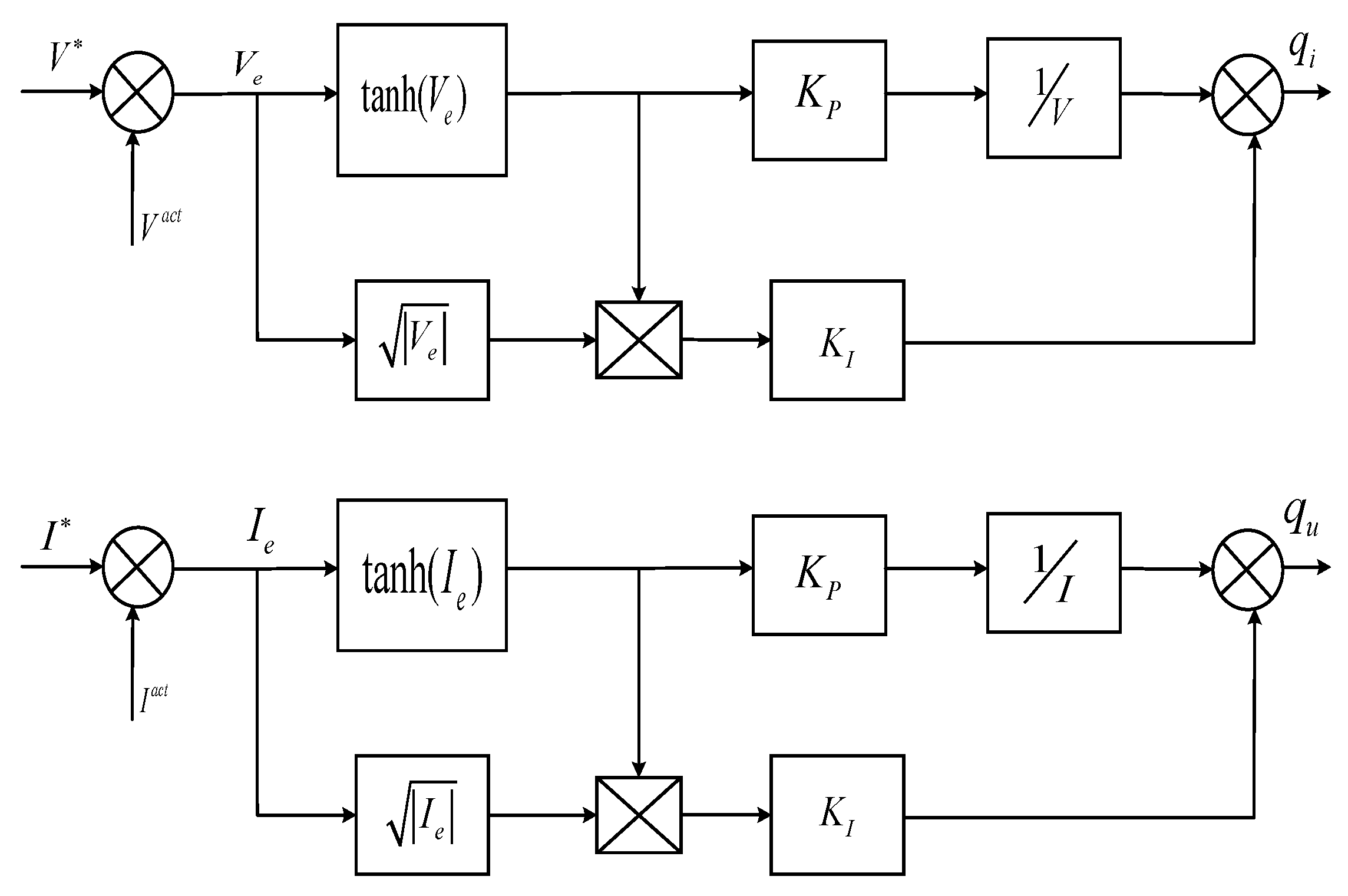
4.1. Design of TSMC Controller

In a grid-connected PV with a battery system, the recommended TSMC controller is utilized in conjunction with the MPOA to manage power issues related to voltage and current. Compared to more conventional controllers such as the proportional–integral (PI) controller and sliding-mode controller (SMC), the TSMC controller offers more flexibility in power management. With its two parameters, the TSMC controller gives the best results in the control process. By delivering ideal pulses, the TSMC controller dramatically lowers error voltage and error current levels. The augmented MPOA method is used to choose these ideal pulses with the goal of minimizing error voltage and error current. Power compensation problems in the grid-connected PV with a battery system are successfully reduced by this TSMC controller by improving the power management system. This section offers a thorough explanation of the TSMC controller.
This work presents the design of a second-order sliding-mode current and voltage controller based on the twisting controller algorithm [26]. Currently, the purpose of initially choosing the voltage sliding surface is as follows:
V e = V V a c t
Consequently, the twisting control algorithm-based second-order sliding-mode voltage controller may be created as follows:
q i = K P V e tanh V e + q i 1 q i 1 = K I tanh V e
where K P and K I , the voltage controller’s settings, can be designed. The voltage of the mover is carefully tracked by the specified reference voltage, using the designed voltage controller, while the power management system is operating in the presence of complex external disturbances. Likewise, based on Equation (12),
d 2 q i d t 2 = P Q q L d q i d t + d L q L v π τ d d i d t ψ f q L d v d t + 1 q L d q u d t
The d- and q-axis voltages in the rotating coordinate system are represented by d u and q u in the formula above; d i and d q represent the voltage and current; and the d- and q-axis currents are represented by d L and q L , respectively. PQ is the real and reactive power of the power management system. PQ, d L , q L , and ψ f , the necessary and sufficient criteria for finite-time convergence, are limited quantities in this case.
At this stage, the current sliding surface’s function is first chosen as follows:
I e = I I a c t
The second-order sliding-mode control is called the twisting algorithm and utilizes both the sliding surface and the derivative of the sliding surface to compute the control signals. This method maintains the following technologic characteristics: the finite-time convergence, the high disturbance robustness, and the low chattering properties, which are important properties of accurate power control in PV systems. In contrast to the first-order sliding modes, whose control has been provided based on single-layer error, the twisting algorithm contributes more accuracy and robustness in controlling the given system because it works with dual-loop correction, which is very applicable in environments with high dynamics of energy, like the grid-connected PV battery and EV systems.
Consequently, the twisting control algorithm-based second-order sliding-mode current controller may be created as follows:
q u = K P I e tanh I e + q u 1 q u 1 = K I tanh I e
where K P and K I , the present controller’s settings, can be calculated.
Figure 2 displays the block diagram of the twisting sliding-mode controller created using Equations (11) and (14).
The applied control rule is far more complex than the proportional controller scenario depicted in Figure 2. The twisting sliding-mode controller (TSMC) is a second-order discontinuous sliding-mode control technique that serves as the foundation for this controller. Its control signals are dynamically changed in relation to the sliding surface and its time derivative. Although the picture depicts a high-level abstraction, the inside method features a nonlinear control logic that ensures durable convergence and a decrease in noise.

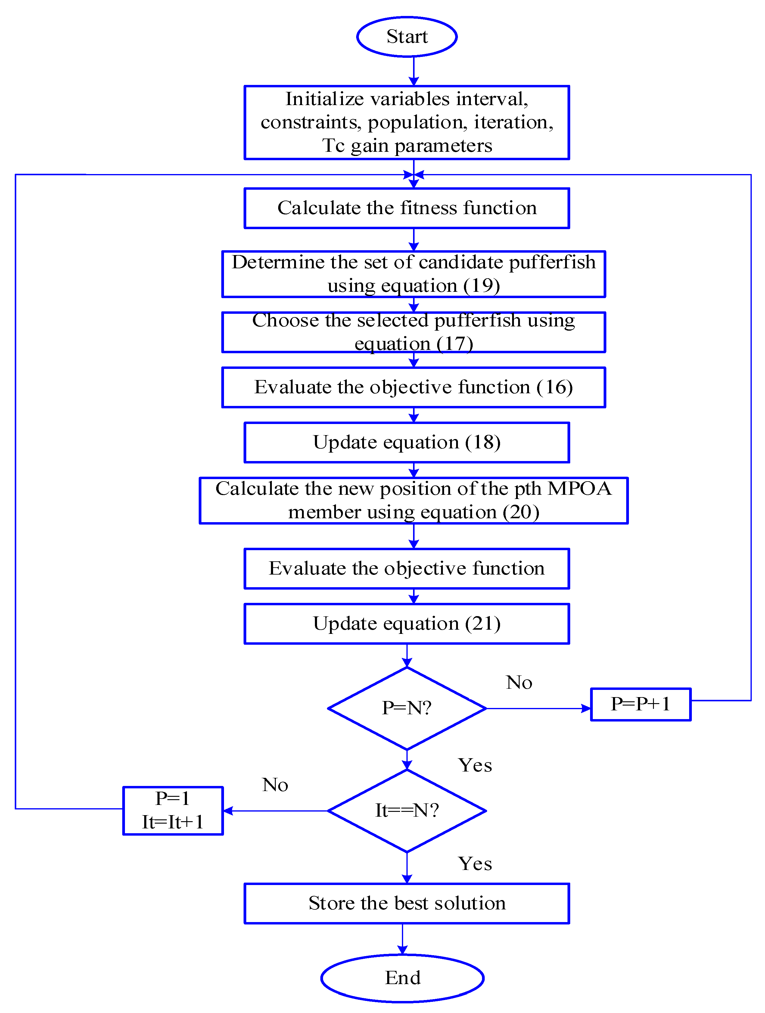
4.2. Optimization of Gain Parameter for Power Management Utilizing MPOA

The best values for accomplishing power management in the power management control structure are found using the MPOA, and they are used to obtain the optimum values of the parameters of the TSMC controller. Pufferfish belong to the Tetraodontidae family and Tetraodontiformes order of fish, mostly found in the sea and estuaries. The pufferfish resembles the large-spiked porcupinefish morphologically. Pufferfish have tiny-to-medium-sized bodies, and they may reach a maximum length of 50 cm. The four teeth on a pufferfish’s beak are one of their most distinguishing characteristics. Another distinctive feature of pufferfish is its lack of ribs, pelvis, and pectoral fins [27].
  • Step 1: Initialization
The population of the algorithm is made up of all POA members together. From a mathematical perspective, a matrix may be used to describe the input of error voltage, current, TSMC gain parameters, and community of these vectors, as shown by Equation (15).
R = R 1 R i R n n × l
where R i is the ith POA member (candidate solution), n is the number of population members, l is the number of decision factors, and R is the population matrix.
  • Step 2: Fitness Function
The main goal of this study is to propose an IPMC that is efficient and achieves the generated power and required power.
O F p = G P = R P
where G P and R P are the generated power and required power, respectively. Fitness is dependent on load demand, for which PV and battery generation provide electricity. The algorithm is employed to obtain the desired level of fitness.
  • Step 3: Predator Attack on Pufferfish during the Exploration Stage
The position of the population members is updated in step 3 of the MPOA based on a simulation of the predator’s attack plan directed at the pufferfish. It is believed that the predator chooses one pufferfish at random from the candidate pufferfish, P F C , identified in the set; this pufferfish is referred to as the selected pufferfish P F S . Equation (17) is used to determine each MPOA member’s new position in the problem-solving space based on the modeling of the predator’s progress toward the pufferfish. Then, in accordance with Equation (18), if the goal function value is increased in the new position, that new location takes the place of the corresponding member’s prior position.
r p , q E r p = r p , q + r a n d p , q P F S p , q δ p , q r p , q
R p = R p E r p , O F p E r p O F p R p , E l s e
where
P F C p = R I t : O F I t < O F p   a n d   I t p
where R p E r p is the new position calculated for the pth predator based on the first phase of the proposed POA; O F p E r p is the objective function value; P F S p is the selected pufferfish for the pth predator chosen randomly from the P F C p set (i.e., P F S p is an element of the P F C p set); r p , q E r p is its qth dimension; r a n d p , q represents random numbers from the interval [0, 1]; and δ p , q represents random numbers selected as 1 or 2.
  • Step 4: Pufferfish’s Defense Mechanism (Exploitation Phase) against Predators
Based on a modeling of a pufferfish’s defensive mechanism against predator assaults, the location of population members is updated in step 4 of the MPOA. A pufferfish fills its very elastic stomach with water to transform into a ball of pointed spines when it is assaulted by a predator. In response, the predator flees from the pufferfish’s location rather than taking an easy meal in the face of such a warning. By simulating the predator’s retreat from the pufferfish, the MPOA members’ positions are slightly altered, which boosts the algorithm’s capacity for local search exploitation. Equation (20) is used to determine a new location for each POA member based on the modeling of the predator’s position shift when moving away from the prey. Then, in accordance with Equation (21) this new location replaces the corresponding member if it increases the value of the objective function.
r p , q E i p = r p , q + 1 r a n d p , q U B q L B q I t
R p = R p E i p , O F p E i p O F p R p , E l s e
where t is the iteration counter, O F p E i p is the objective function value, r p , q E i p is its qth dimension, R p E i p is the new location estimated for the pth predator based on the exploitation phase of the proposed POA, and r a n d p , q represents the random values from the interval [0, 1].
  • Step 5: Repetition Process
The first iteration of the algorithm is finished by updating the positions of all MPOA members depending on the phases of exploration and exploitation. The algorithm then moves on to the following iteration, and up to the last iteration, Equations (17) through (21) are used to update the positions of MPOA members. Based on a comparison of the assessed values for the objective function, the best MPOA member’s position is updated and saved at the end of each iteration. These fitness functions are used to calculate the gain parameters of the TSMC controller. A final condition check becomes essential before implementing the optimal solutions, considering factors such as reaching the maximum number of iterations and verifying constraints. The perfect power management in the grid-integrated EV with a PV and battery system is then achieved by using optimal solutions. The system’s voltage and current error problems are successfully mitigated by using the improved MPOA. The execution steps are given in Figure 3.
The combination of the TSMC and MPOA has some advantages: the TSMC is used to deliver robust real-time control of voltage and current, and the MPOA can be used offline or online for optimization of the parameters of the dynamics. The TSMC uses gain parameters, K v and K i , to control the system’s voltage and current using second-order sliding-mode surfaces that are defined by Equations (22) and (23).
S i t = d d t I r I t + ρ i I r I t
S v t = d d t V r V t + ρ v V r V t
The control law is defined as Equation (24):
c t = K v · s i g n S v K i · s i g n S i
Although fixed gains are suboptimal in control, the MPOA adjusts the parameters K v and K i to minimize a cost function that is assumed to reduce tracking errors and enhance stability, as shown in Equation (25).
J K v , K i = t = 0 T α · V r t V t + β · I r t I t + γ · c t 2
where c t denotes the control output; α , β , and γ are the weighting coefficients; and the optimization domain is constrained to stable gain ranges, K m i n and K m a x . The search of this space is conducted by an adaptive predator–prey-inspired strategy by the MPOA. The minimum voltage and current deviation K v   a n d   K i found are optimal values that are injected into the TSMC in tuned design parameters.
The TSMC’s capabilities of pushing state trajectories onto the sliding surface in finite time are connected to the convergence speed of the control system. The MPOA conducts the optimal selection of gain pairs to minimize the sliding time-condition ( s ( t ) = 0 ) that can evidently be seen in the reduced rising time and settling time, as in the simulation results. Additionally, compared with standard controllers such as the BWO and MGO, the suggested MPOA-TSMC architecture has a much faster convergence speed and smaller load transient over-shoot.
Though the finite-time stability may not be formally proven with Lyapunov, as it is out of the scope of this research, the design guarantees the closed-loop behavior of the system being convergent asymptotically with smaller chattering that meets the following condition:
V ^ S = 1 2 d d t S 2 η S s ( t ) 0
This disparity proves that the best gain adjustment maintains gliding stability and enhances convergence measures empirically, thus validating the advantage of the MPOA in steering the conduct of the TSMC.
The TSMC is a second-order sliding-mode controller which ensures finite-time convergence property, enhanced robustness in the face of external disturbances, and substantially less chattering effects of first-order SMC. Such characteristics make it especially suitable to applications with unsure and dynamically fluctuating systems, such as PV-EV–grid combinations. The MPOA is based on the behavior of the ability of pufferfish to defend against the attack and escape, and it is outstanding in terms of the balance between global search and local search. In contrast to the traditional algorithms, its dynamic, dual-phase approach of predator attacks and defense is further assisted by resisting the collapse converge and enhancing the diversification of solutions. These features make it best for optimizing the evaluation of TSMC gain parameters, convergence speed, and reduction of voltage and current error functions in order to allow for the optimization of the entire power management strategy. The innovation of TSMC computing combined with the MPOA can make the proposed intelligent power management have better control precision, robustness, and energy efficiency than any other techniques.
The subsequent section provides a comprehensive overview of the findings and discusses them.

5. Results and Discussion

This section utilizes the suggested algorithmic regulator’s competence to provide power to the executives inside the framework of the intelligent power management controller. The IPMC is examined for testing using the MATLAB/Simulink 7.10.0 (R2022a) platform and an Intel(R) Core (TM) i5 CPU with 4 GB RAM. The optimal convergence is achieved by the improved interaction between the MPOA and the suggested TSMC. Figure 4 depicts the suggested paradigm for MATLAB/Simulink execution. The detailed system and simulation parameters used in this study are summarized in Table 1. Three characteristics were taken into consideration for the experimental analysis: power, irradiation, and PV power system. It was derived by considering the interpolation approach that was used on measured data points that corresponded to potential operational voltage outputs, such power keys. Lastly, the results of this suggested approach are contrasted with those of the Mountain Gazelle Optimizer (MSO) and Beluga Whale Optimization Algorithm (BWO) techniques.

5.1. Performance Analysis of Proposed Power Management Controller Using MPOA Method

To maximize energy flow, the suggested power management controller effectively combines PV panels, batteries, EVs, and the grid. The controller provides backup power, load shifting, peak shaving, and optimal performance by assessing output power depending on time in hours and samples. Midday is when PV production peaks, batteries go through cycles of charge and discharge, EVs control charging and discharging, and the grid manages to provide load-demand electricity and exports. The power management system’s dependability and affordability are improved by this dynamic modification.
The performance study of PV power and solar irradiance in sample-based time and hours is depicted in Figure 5. The PV irradiation is examined using sample-based timing in Figure 5a. The irradiation stays constant in sample-based time between 0 and 1.8. The irradiation is found to be 6.9 × 10⁵ W/m2 in sample-based time between 1.8 and 7.5, and the irradiance stabilizes once more between 6.9 × 10⁴ and 9 × 10⁴ in sample-based time. Figure 5c shows that the highest PV power is 750 W at 24 h, whereas Figure 5b shows that the maximum PV power production is 6.25 × 10⁵ W at 9 × 10⁴ sample-based time.
Figure 6 depicts the results of a comprehensive investigation of the battery computer performance in regard to (a) current, (b) SOC, and (c) stored energy within a 6 s simulation run. All of these plots show overall dynamic behavior of the battery through charge and discharge cycles enabled by the proposed IPMC.
Figure 6a shows the battery current oscillating between zero (negative and positive), that is, the charging state and discharging state, respectively. As an example, from 1 s to 2.5 s, the current reaches its highest point (10 A), meaning that the battery is charged. Between 2.5 s and 3.5 s the current is reduced (nearly 0 A) in a hold state and then increases again, presumably when there is an exchange of power again. Figure 6b represents the SOC evolution according to the current profile. SOC decreasing behavior at the discharge window (before 3 s), stabilizing phenomena thereafter, and an increasing behavior at the start of charging phase (above 4 s) can be seen. The relationship between the current input and SOC is clear: when discharging (negative or zero current), the SOC goes down or flat; and when charging (positive current), it goes up. Figure 6c shows that the stored energy behavior is the replica of the SOC performance. Energy is lower in discharge times (0–3 s); it reaches the lowest value at 3 s and begins to increase after 4 s. The energy profile therefore indicates that the controller efficiently handles battery functions by responding in a proper way to the demands of the system. The result mentioned above indicates that the proposed controller is effective in coordinating battery charging/discharging operations in accordance with the PV generation and the EV/load demands in real-time and balancing the available energy, as well as enhancing its use efficiency.
Figure 7 presents the analysis of battery output, in terms of power, using the proposed power management controller. In Figure 7a, the power is plotted against time in 24 h, illustrating daily variations and highlighting periods of maximum peak power, i.e., 400 W, and low power output, i.e., −400 W. Figure 7b provides a more granular view by plotting power against sample-based time, capturing detailed fluctuations in power from 4 W × 105 to −4 W × 105 at specific intervals, 0 to 9 × 10⁴. Figure 8 presents the performance analysis of the EV using the proposed power management controller. In Figure 8a, the EV power output over a 24 h period is shown, starting at 400 W, decreasing to 250 W, then rising to 625 W, and finally dropping to 410 W. Similarly, Figure 8b provides a more detailed representation of these variances by plotting the EV power output over sample-based time. These evaluations show how well the controller controls battery and electric vehicle (EV) power consumption, maximizes energy efficiency, and maintains consistent power distribution throughout the day. The power detected in Figure 8 corresponds to a simulated light EV. The simulation scenario was designed to validate the controller’s precision at low loads, where power fluctuations are more sensitive. The IPMC can be easily scaled to handle higher-capacity EVs by adjusting system parameters and controller limits, which will be addressed in future work.
Figure 9 shows the grid output as (a) power, (b) price over 24 h, and (c) price over sample-based time. The reviewer’s objection is valid, and we have narrowed our interpretation to make the trends and implications of these results clearer. In Figure 9a, the grid power profile indicates the dynamic response of the system due to PV contribution and load demand during the day. Grid power consumption decreases during solar peak hours because of increased PV contribution; and during early morning and evening hours, when solar irradiance is low, grid power consumption increases to match the load demand. This indicates the flexibility of the controller in lowering grid dependence during high renewable-energy-availability hours. Figure 9b represents the cost of grid electricity through a 24 h period. Costs are cheaper in off-peak hours and more expensive during peak demand hours. The smart controller takes this into account to plan for use of the power supply accordingly, using PV and battery sources during high-tariff hours, and sourcing from the grid only as needed. This action reduces the total energy cost and fits into modern smart-grid demand–response schemes. Figure 9c also expands on the grid price in sample-based temporal resolution, enabling us to see, at the granular level, variations and how the controller dynamically reacts to them. This granularity captures the internal simulation’s decisioning logic that reacts not just to available energy but also to price incentives. The produced power and required power are summarized in Figure 10. Red is used to indicate the needed power, while blue is used to represent the generated power. This investigation demonstrates that improved power management is achieved by the suggested controller. The devised system smartly synchronizes PV output, battery storage, and grid imports/exports based on real-time pricing signals, thereby accomplishing both operational efficiency and economic optimality.
Simulations were performed within a range of −25 °C to + 55 °C to determine thermal robustness when thermal control is applied to a 100 kW photovoltaic system with a thermally controlled lithium-ion battery pack. As displayed in Table 2, PV output drops to 12% at high temperatures due to decreasing PV outputs in the temperature-influenced atmosphere, but battery efficiency does not reduce with temperatures above 92 percent in the presence of the thermal management system. The IPMC performance is still very reliable; the tracking error is less than 0.045 RMS in each instance, even despite such stresses. This ensures that the controller is suitable in deployments within a tropical climate, as well as within a cold climate.

5.2. Comparison Analysis

The suggested power management controller for the battery-powered, grid-connected PV system is assessed in comparison to other techniques, including the BWO and MGO. The various benchmarking modes and the predicted performance attained by each approach are shown in Figure 11, Figure 12 and Figure 13. The efficacy of the suggested assessment is illustrated through comparison, underscoring its capacity to improve system efficiency and optimize power management. This assessment offers insightful information about the suggested controller’s performance and validates its ability to surpass conventional approaches and enhance system performance.
Using the suggested power management controller, BWO, and MGO approaches, Figure 11 compares (i) PV power with (ii) EV power. The greatest PV-power output power that can be obtained using the suggested controller is 750 W, whereas the 24 h outputs of the BWO and MGO techniques are 735 W and 720 W, respectively. Comparably, the suggested controller’s maximum output power for EV power is 625 W, whereas the 24 h outputs of the BWO and MGO systems are 610 W and 585 W, respectively. This comparison shows that the suggested controller outperforms the conventional BWO and MGO techniques in terms of performance and system efficiency when it comes to maximizing both PV and EV power outputs. A comparison of (i) battery power and (ii) battery energy when utilizing the suggested power management controller, BWO, and MGO approaches is shown in Figure 12. The suggested controller produces a steady 400 W output for battery power over a 24 h period, whereas the BWO and MGO approaches provide lower power outputs with significant oscillations. This suggests that the suggested approach offers the battery a more consistent and dependable power supply. Comparatively speaking, the suggested controller outperforms the BWO and MGO techniques in terms of battery energy, achieving a maximum energy of 2000 kW-h over a 24 h period. This indicates that, in comparison to conventional approaches, the suggested method efficiently utilizes the energy stored in the battery, guaranteeing higher energy efficiency and system dependability. All things considered, the comparison study demonstrates how much better the suggested power management controller performs than the BWO and MGO approaches at maximizing battery power and energy.
A comparison of grid power and grid price utilizing the proposed power management controller, BWO, and MGO approaches is shown in Figure 13 and Figure 14, respectively. The suggested controller outperforms BWO and MGO techniques in terms of performance and power-output stability over a 24 h period, as evidenced by its greater maximum output of 900 W for grid power. This illustrates how well the suggested strategy works to maximize grid electricity usage. In terms of grid pricing, the suggested controller may attain a maximum price of INR 25/kWh, but the BWO and MGO approaches produce higher rates of INR 30/kWh and INR 37/kWh, respectively. This demonstrates that the suggested strategy reduces grid power costs by effectively controlling energy consumption and maximizing processes that are sensitive to price. Overall, the comparison study shows that the suggested power management controller is more successful than conventional BWO and MGO approaches at optimizing grid power and pricing, thus improving system efficiency and reduces costs. A comparative study of convergence graphs is shown in Figure 15, which also shows the performance of the suggested power management techniques over a thousand iterations. In comparison to more established techniques like BWO and MGO, this suggests that the suggested method efficiently converges towards optimal solutions, guaranteeing dependable and efficient power management. The convergence graph sheds an important light on the convergence behavior of the suggested approach and demonstrates how well it works to improve system performance and reliability by reaching optimal solutions in a manageable number of repetitions.
Though the proposed IPMC works well in ensuring optimal PV output follow-up and battery usage in the regular presentation of dynamic situations, the consideration of such situations that may arise when things become twisted (e.g., sudden loss of PV, battery performance failures, and/or grid price shocks) is also an important factor that must be considered. In such cases, one can incorporate a conditional risk assessment technique like Conditional Value at Risk (CVaR) in an optimization plan of strategy. The concept of the CVaR-based framework presented in [28] is an effective tool for measuring the risks in the tail-end of risks related to low-probability but high-impact events. Applied to energy systems, CVaR could assist in measuring the worst-case excursions in supply of power, cost, and system stability. As has not been performed in the present case, adding a CVaR objective function to future versions of the MPOA may prove useful in making the approach more robust, even in stochastic settings. It would help the controller to minimize mean performance, as well as reduce the tail-risk exposure of uncertain PV generation and load situations.

6. Conclusions

This study proposed IPMC which TSMC is to integrate MPOA that was implemented in both grid-integrated photovoltaic systems and files of EV applications. The hybrid control strategy could regulate most of the power between the PV arrays, battery storage, EV loads, and utility grid in a robust way, under variable conditions, by controlling the voltage and current. The simulation determined that the TSMC achieves finite-time convergence and high resilience to disturbances caused by perturbations, and MPOA performs optimal tuning of controller parameters, with improved dynamic performance and reduced tracking errors. The proposed method had faster convergence, smoother transient dynamics, and improved energy efficiency compared to the corresponding benchmark algorithms. It also demonstrated excellent temperature robustness and potential scaling compared to full-fledged EV and smart grid systems, with the controller. Multi-agent collaborative optimization may be presented with future investigation introducing an asymmetric Nash bargaining (NB) arrangement to allocate profits in a fair manner in accordance with the contribution of each agent and the TPCA-ADMM algorithm to enhance privacy-conserving and a distributed scheduling of power. It also helps coordinate PV plants, EV charging stations, and battery systems at scale, as suggested in [29], making the proposed IPMC based more on real-life smart grid applications.

7. Limitations and Future Work

While the proposed intelligent power management controller (IPMC) demonstrates robust performance across various scenarios, certain modeling assumptions limit the real-world applicability of the results. The photovoltaic (PV) generation model does not incorporate detailed meteorological variations such as cloud cover, shading, temperature-induced efficiency degradation, or seasonal angle variations. Similarly, the electric vehicle (EV) load model is based on a fixed daily demand profile without accounting for stochastic user behaviors, such as variable arrival/departure times, charging preferences, or dynamic driving patterns.
In real-world smart grid environments, both PV generation and EV charging exhibit high variability and uncertainty. Incorporating probabilistic or data-driven forecasting models, such as those based on Markov chains or deep learning, could enhance modeling realism. Future work should also consider real-time control scenarios with vehicle-to-grid (V2G) interactions and multi-agent collaborative optimization to scale the system for larger deployments.

Author Contributions

Conceptualization, A.K.S. and R.K. (Rohit Kumar); methodology, I. and A.K.S.; software, G.S.; validation, P.N.B. and G.S.; formal analysis, A.K.S.; investigation, R.K. (Rohit Kumar); resources, D.K.C.; data curation, R.K. (Rohit Kumar) and D.K.C.; writing—original draft preparation, A.K.S. and R.K. (Rohit Kumar); writing—review and editing, R.K. (Rohit Kumar) and R.K. (Rajesh Kumar); visualization, A.K.S.; supervision, I., G.S. and R.K. (Rajesh Kumar); project administration, P.N.B.; funding acquisition, P.N.B. All authors have read and agreed to the published version of the manuscript.

Funding

This research received no external funding.

Data Availability Statement

The raw data supporting the conclusions of this article will be made available by the authors upon request.

Conflicts of Interest

The authors declare no conflicts of interest.

Abbreviations

PVphotovoltaic
EVelectric vehicle
IPMCintelligent power management controller
TSMCtwisting sliding-mode controller
MPOAModified Pufferfish Optimization Algorithm
SOCstate of charge
GAgenetic algorithm
ANNartificial neural network
SMCsliding-mode controller
MPPTmaximum power point tracking
BWOBeluga Whale Optimization
MGOMountain Gazelle Optimizer
CVaRConditional Value at Risk
NBNash bargaining
TPCA-ADMMThree-Stage Predictor-Corrected Accelerated ADMM
ADMMAlternating-Direction Method of Multipliers
EMSenergy management system
V2Gvehicle-to-grid
CCCVConstant Current–Constant Voltage
SRF-PLLsynchronous reference frame phase-locked loop
LVRTlow-voltage ride through

References

  1. Amir, M.; Zaheeruddin; Haque, A.; Bakhsh, F.I.; Kurukuru, V.S.B.; Sedighizadeh, M. Intelligent Energy Management Scheme-Based Coordinated Control for Reducing Peak Load in Grid-Connected Photovoltaic-Powered Electric Vehicle Charging Stations. IET Gener. Transm. Distrib. 2024, 18, 1205–1222. [Google Scholar] [CrossRef]
  2. Mohan, H.M.; Dash, S.K. Renewable Energy-Based DC Microgrid with Hybrid Energy Management System Supporting Electric Vehicle Charging System. Systems 2023, 11, 273. [Google Scholar] [CrossRef]
  3. Singh, B.; Kumar, A. Optimal Energy Management and Feasibility Analysis of Hybrid Renewable Energy Sources with BESS and Impact of Electric Vehicle Load with Demand Response Program. Energy 2023, 278, 127867. [Google Scholar] [CrossRef]
  4. Karmaker, A.K.; Hossain, A.; Pota, H.R.; Onen, A.; Jung, J. Energy Management System for Hybrid Renewable Energy-Based Electric Vehicle Charging Station. IEEE Access 2023, 11, 27793–27805. [Google Scholar] [CrossRef]
  5. Huy, T.H.B.; Dinh, H.T.; Kim, D. Multi-Objective Framework for a Home Energy Management System with the Integration of Solar Energy and an Electric Vehicle Using an Augmented ε-Constraint Method and Lexicographic Optimization. Sustain. Cities Soc. 2023, 88, 104289. [Google Scholar] [CrossRef]
  6. Das, N.; Haque, A.; Zaman, H.; Morsalin, S.; Islam, S. Domestic Load Management with Coordinated Photovoltaics, Battery Storage and Electric Vehicle Operation. IEEE Access 2023, 11, 12075–12087. [Google Scholar] [CrossRef]
  7. Rekioua, D. Energy Storage Systems for Photovoltaic and Wind Systems: A Review. Energies 2023, 16, 3893. [Google Scholar] [CrossRef]
  8. Hai, T.; Zhou, J.; Rezvani, A.; Le, B.N.; Oikawa, H. Optimal Energy Management Strategy for a Renewable Based Microgrid with Electric Vehicles and Demand Response Program. Electr. Power Syst. Res. 2023, 221, 109370. [Google Scholar] [CrossRef]
  9. Huy, T.H.B.; Dinh, H.T.; Vo, D.N.; Kim, D. Real-Time Energy Scheduling for Home Energy Management Systems with an Energy Storage System and Electric Vehicle Based on a Supervised-Learning-Based Strategy. Energy Convers. Manag. 2023, 292, 117340. [Google Scholar] [CrossRef]
  10. Boynuegri, A.R.; Tekgun, B. Real-Time Energy Management in an Off-Grid Smart Home: Flexible Demand Side Control with Electric Vehicle and Green Hydrogen Production. Int. J. Hydrogen Energy 2023, 48, 23146–23155. [Google Scholar] [CrossRef]
  11. Fathy, A. Bald Eagle Search Optimizer-Based Energy Management Strategy for Microgrid with Renewable Sources and Electric Vehicles. Appl. Energy 2023, 334, 120688. [Google Scholar] [CrossRef]
  12. Singh, A.K.; Tariq, T.; Ahmer, M.F.; Sharma, G.; Bokoro, P.N.; Shongwe, T. Intelligent Control of Irrigation Systems Using Fuzzy Logic Controller. Energies 2022, 15, 7199. [Google Scholar] [CrossRef]
  13. Ameur, A.; Berrada, A.; Emrani, A. Intelligent Energy Management System for Smart Home with Grid-Connected Hybrid Photovoltaic/Gravity Energy Storage System. J. Energy Storage 2023, 72, 108525. [Google Scholar] [CrossRef]
  14. Beheshtikhoo, A.; Pourgholi, M.; Khazaee, I. Design of Type-2 Fuzzy Logic Controller in a Smart Home Energy Management System with a Combination of Renewable Energy and an Electric Vehicle. J. Build. Eng. 2023, 68, 106097. [Google Scholar] [CrossRef]
  15. Yan, Z.; Duan, X.; Chang, Y.; Xu, Z.; Sobhani, B. Optimal Energy Management in Smart Buildings with Electric Vehicles Based on Economic and Risk Aspects Using Developed Whale Optimization Algorithm. J. Clean. Prod. 2023, 415, 137710. [Google Scholar] [CrossRef]
  16. Al Essa, M.J.M. Power Management of PEV Using Linear Programming with Solar Panels and Wind Turbines in Smart Grids. Electr. Eng. 2023, 105, 1761–1773. [Google Scholar] [CrossRef]
  17. Meenalochini, P.; Priya, R.A.; Pugalenthi, R.; Jagadeeshwaran, A. Energy Management of Grid Connected PV with Efficient Inverter Based Wireless Electric Vehicle Battery Charger: A Hybrid CSA-QNN Technique. J. Energy Storage 2024, 80, 110255. [Google Scholar] [CrossRef]
  18. Sathyan, S.; Pandi, V.R.; Antony, A.; Salkuti, S.R.; Sreekumar, P. ANN-Based Energy Management System for PV-Powered EV Charging Station with Battery Backup and Vehicle to Grid Support. Int. J. Green Energy 2024, 21, 1279–1294. [Google Scholar] [CrossRef]
  19. Nouri, A.; Lachheb, A.; El Amraoui, L. Optimizing Efficiency of Vehicle-to-Grid System with Intelligent Management and ANN-PSO Algorithm for Battery Electric Vehicles. Electr. Power Syst. Res. 2024, 226, 109936. [Google Scholar] [CrossRef]
  20. Li, B.; Li, Z.; He, D. Research and Optimization of Energy Management System for Photovoltaic Vehicles. Energy 2024, 289, 129776. [Google Scholar] [CrossRef]
  21. Aldbaiat, B.; Nour, M.; Radwan, E.; Awada, E. Grid-Connected PV System with Reactive Power Management and an Optimized SRF-PLL Using Genetic Algorithm. Energies 2022, 15, 2177. [Google Scholar] [CrossRef]
  22. Rajaram, K.; Kannan, R. Design and Implementation of Adaptive Pufferfish Optimization Algorithm Based Efficient MPPT and DC–DC Boost Converter for Agriculture Applications under Partial Shading Conditions. Intell. Decis. Technol. 2024, 19, 1074–1090. [Google Scholar] [CrossRef]
  23. Singh, A.K.; Kumar, K.; Choudhury, U.; Yadav, A.K.; Ahmad, A.; Surender, K. Applications of Artificial Intelligence and Cell Balancing Techniques for Battery Management System (BMS) in Electric Vehicles: A Comprehensive Review. Process Saf. Environ. Prot. 2024, 191, 2247–2265. [Google Scholar] [CrossRef]
  24. Farook, S.; Thrinath, B.V.; Lakshmi, U.R.; Likhitha, N. An Integrated Vehicle-To-Grid and Solar System for Energy Management and Optimization. In Proceedings of the 2024 Second International Conference on Smart Technologies for Power and Renewable Energy (SPECon), Ernakulam, India, 2–4 April 2024; pp. 1–6. [Google Scholar] [CrossRef]
  25. Zou, B.; Peng, J.; Li, S.; Li, Y.; Yan, J.; Yang, H. Comparative Study of the Dynamic Programming-Based and Rule-Based Operation Strategies for Grid-Connected PV-Battery Systems of Office Buildings. Appl. Energy 2022, 305, 117875. [Google Scholar] [CrossRef]
  26. Ullah, S.; Hayat, R.; Zeb, K.; Rasheed, A.; Muyeen, S.M. Super-Twisting Sliding Mode Controller for Energy Storage System of a Novel Multisource Hybrid Electric Vehicle: Simulation and Hardware Validation. Int. J. Hydrogen Energy 2024, 71, 952–963. [Google Scholar] [CrossRef]
  27. Al-Baik, O.; Alomari, S.; Alssayed, O.; Gochhait, S.; Leonova, I.; Dutta, U.; Malik, O.P.; Montazeri, Z.; Dehghani, M. Pufferfish Optimization Algorithm: A New Bio-Inspired Metaheuristic Algorithm for Solving Optimization Problems. Biomimetics 2024, 9, 65. [Google Scholar] [CrossRef]
  28. Zhai, X.; Li, Z.; Li, Z.; Xue, Y.; Chang, X.; Su, J.; Jin, X.; Wang, P.; Sun, H. Risk-Averse Energy Management for Integrated Electricity and Heat Systems Considering Building Heating Vertical Imbalance: An Asynchronous Decentralized Approach. Appl. Energy 2025, 383, 125271. [Google Scholar] [CrossRef]
  29. Ding, B.; Li, Z.; Li, Z.; Xue, Y.; Chang, X.; Su, J.; Sun, H. Cooperative Operation for Multiagent Energy Systems Integrated with Wind, Hydrogen, and Buildings: An Asymmetric Nash Bargaining Approach. IEEE Trans. Ind. Inform. 2025, 21, 6410–6421. [Google Scholar] [CrossRef]
Figure 1. Schematic representation of the proposed intelligent power management system.
Energies 18 03785 g001
Figure 2. Twisting sliding-mode controller.
Energies 18 03785 g002
Figure 3. Flowchart of proposed Modified Pufferfish Optimization Algorithm.
Energies 18 03785 g003
Figure 4. Grid-connected PV system MATLAB/Simulink diagram with proposed power management controller.
Energies 18 03785 g004
Figure 5. Performance analysis of (a) solar irradiance, (b) PV power in sample-based time, and (c) PV power in time (hours).
Energies 18 03785 g005aEnergies 18 03785 g005b
Figure 6. Performance analysis of battery output: (a) battery current, (b) state of charge (SOC), and (c) battery energy.
Energies 18 03785 g006aEnergies 18 03785 g006b
Figure 7. Analysis of battery output in (a) power (hours) and (b) power (sample-based time).
Energies 18 03785 g007
Figure 8. Analysis of EV output in (a) power (hours) and (b) power (sample-based time).
Energies 18 03785 g008
Figure 9. Analysis of grid output in (a) power, (b) price (hours), and (c) price (sample-based time).
Energies 18 03785 g009aEnergies 18 03785 g009b
Figure 10. Performance analysis of a generated power with required power.
Energies 18 03785 g010
Figure 11. Comparative analysis of (i) PV power and (ii) EV power.
Energies 18 03785 g011
Figure 12. Comparative analysis of (i) battery power and (ii) battery energy.
Energies 18 03785 g012aEnergies 18 03785 g012b
Figure 13. Comparative analysis of grid price based on time.
Energies 18 03785 g013
Figure 14. Comparative analysis of grid power based on time.
Energies 18 03785 g014
Figure 15. Comparative analysis of convergence graph.
Energies 18 03785 g015
Table 1. System parameters.
ParametersAlgorithmValue
Nominal voltageBattery5000 V
Nominal frequency60 Hz
Nominal voltagePV5000 V
Nominal frequency60 Hz
Initial power500 × 103
Nominal voltageEV5000 V
Nominal frequency60 Hz
Power factor1
Initial load200 × 103
Population sizeMPOA50
No of variables10
Maximum iteration100
Lower bound−5
Upper bound5
Table 2. Thermal robustness analysis of IPMC.
Temperature (°C)Max PV Output (KW)Battery Efficiency (%)Tracking Error (RMS)
−2512092.00.045
−1011492.00.038
25 (nominal)10095.00.020
409493.50.028
558892.00.035
Disclaimer/Publisher’s Note: The statements, opinions and data contained in all publications are solely those of the individual author(s) and contributor(s) and not of MDPI and/or the editor(s). MDPI and/or the editor(s) disclaim responsibility for any injury to people or property resulting from any ideas, methods, instructions or products referred to in the content.

