1. Introduction
In the relatively small synchronous area that is the Nordic electrical power grid, reduced inertia has been identified as a key influencing factor for the grid frequency quality. The reduction in inertia is caused by both decommissioning of nuclear power plants and the expanded possibilities to connect both sources and loads through power electronics. However, the development of power electronics has also given the possibility to synthesize inertia in the controllers to act like synchronous electrical machines. The compromise is most likely to be market-driven, not requirement-driven. In deregulated frequency control markets, the transmission system operator (TSO) relies on external parties to provide ancillary services, but no real inertia replicator is currently being used. Instead, replacement products in terms of faster-acting frequency control systems are being introduced, denoted as fast frequency response (FFR). Ongoing work to renew technical requirements for primary frequency control is clearly affected by inertia prognoses in that, e.g., stability criteria are parameterized with the minimal foreseen inertia level [
1]. Instead of simpler frequency step responses, both stability and performance criteria are now in place to qualify units for Frequency Containment Reserve (FCR). In this regard, the Nordic system is a precursor of a development that most likely will also take place in other power systems if they have not already done so.
The intention to mitigate a lack of inertia by primary frequency control actions results in criteria that are too hard to fulfill for many of the units currently delivering primary frequency control, cf. [
2]. Given the above, Nordic Transmission System Operators (TSOs) investigate the possibility to obtain separate delivery of mechanical or virtual/synthetic inertia to increase the frequency stability.
In reality, it is hard to find suppliers of inertia, synthetic or mechanical, for all operating conditions during a year, which has forced the TSOs to use alternative means to handle the challenge of low inertia. In some power systems, synchronous generators are forced to be grid-connected at zero power. This can be seen in the renewed interest in synchronous condensers.
1.1. Different Approaches for Inertia Replacement
The inertial response of an electrical machine gives a power deviation proportional to the mechanical angular acceleration times the angular speed. For a synchronously connected machine, the mechanical angular speed and acceleration correspond to the complementary electrical property, i.e., to the grid frequency, except for the deviations referred to as rotor angle oscillations. Effectively, the inertial response of these machines naturally act to oppose frequency deviations, which is the ideal behavior that is meant to be replicated.
An approach to obtain a power contribution that mimics this inertial response is to measure the frequency of the grid and compute the desired response from the frequency derivative, sending this control signal to an inverter connected to a stored energy source. This is what we refer to assynthetic inertia (SI). Another approach is to measure the actual power variations given off by a synchronous machine operating at a stationary point and to amplify them. This is what we refer to as amplified inertia response (AIR). In both approaches, the final step is to deliver the desired response from an electrical energy storage system. Yet another approach is to mimic the behavior of a synchronous generator by implementing a virtual synchronous generator (VSG) controller [
3] in an inverter. The VSG controller can be implemented in power electronics-connected generation, which may allow renewable energy sources to contribute to grid stability [
4,
5]. The VSG controller will not be covered in this paper, since it resembles and presents similar challenges to what we denote as synthetic inertia.
1.2. Related Work
Synthetic or virtual inertia, in the meaning adopted in this paper, is studied in several publications. In [
6], the terms are used interchangeably, and intrinsically linked to the frequency derivative, or Rate of Change of Frequency (RoCoF). In [
7], the frequency is evaluated with a phase-locked loop, allowing the calculation of its derivative and enabling synthetic inertia through the use of battery energy storage.
However, the evaluation of the RoCoF is not trivial. Since derivative calculations amplify high-frequency noise, such evaluation becomes challenging. The use of a frequency-locked loop as a synchronism circuit has been proposed instead of phase-locked loops [
8]. In fact, when inertia methods have been discussed, a second-order generalized integrator–frequency-locked loop (SOGI-FLL) seems to be a much-utilized method [
9,
10]. Some grid-forming inverters [
11] and wind turbines providing ancillary services also propose versions of SOGI-FLLs [
12].
It should be noted that the issue of high-frequency noise amplification is not the only challenge to be tackled. The use of digital controllers to evaluate RoCoF and perform the synthetic inertia also introduces delays and thus cannot truly substitute natural inertia from synchronous machines, which must still be included in some portion in the optimal solution for grid support [
13].
In some extent, other forms of simulated inertia have been proposed, so as to not depend on the calculation of the derivative of the frequency. In [
14], frequency deviations from the operational point are used to calculate required voltage deviations on the dc link of an inverter, such that the dc capacitance exports or imports power such that it opposes deviations in frequency. Similar capacitive-based inertial responses, not intended to mimic physical inertia in its direct relation to frequency derivative, are seen in [
15].
There are also alternative terms for what we denote by synthetic inertia, such as virtual synchronous machines [
4,
16,
17]. This approach of inertia emulation involves the use of its own swing equation for synchronous machines in the controlled design of the grid-connected inverter. A comprehensive comparison between SI methods and VSG is shown in [
18], where the noise amplification due to derivative calculations is explicitly mentioned as a drawback of the former, while the latter introduces unwanted stability problems related to rotor angle oscillations. Still, the use of virtual synchronous machines has been prominent in the literature, making use of hybrid storage solutions such as batteries and supercapacitors [
19] or directly through renewable resources such as PV generation [
20].
It should be noted, however, that by emulating the swing equation, the VSG will still require the calculation of the frequency derivative. And by not using a synchronism circuit such as the PLL to determine grid frequency, the VSG avoids the extreme noise amplification issue seen in the SI method, but will still introduce delays that hinder it from achieving the same performance as a natural synchronous machine. As such, VSG methods will be treated in this work as not dissimilar to other synthetic inertia methods.
Other alternatives are synchronous condensers, which give an inertial response, increase the short-circuit current [
21,
22], and enhance oscillatory behavior [
23]. Synchronous condensers are also shown to work in conjunction with synthetic inertia for increased frequency stability [
24].
Thus, although synthetic inertia has been shown to be a very valuable resource for grid support, its performance limitations caused by delays and noise amplification point towards the need for additional solutions. This gap is tackled by this paper with the proposal of using inverter-based resources to amplify the measured inertial response of grid-connected synchronous machines, thus avoiding the noise amplification and delay issues caused by derivative-based methods.
To the best of our knowledge, nothing has been published in academic journals on the amplified inertia response. The idea has been presented in a patent application [
25], yet here, we compare it experimentally to synthetic inertia methods in a microgrid setup. The tests of synthetic inertia in the literature often apply the use of microgrids [
26,
27,
28,
29,
30], since they provide a controlled environment for tests and allow for a larger frequency deviations than the actual grid.
1.3. Paper Structure
This paper is divided as follows.
Section 2 describes the method of the tests, along with the detailed implementation of two virtual inertia methods in
Section 2.1 and the amplified inertia in
Section 2.2. The results are shown in
Section 3, separated in subsections for the laboratory microgrid test in
Section 3.1 and the grid-connected test in
Section 3.2. Finally, some discussions are presented in
Section 4, with conclusions being summarized in
Section 5.
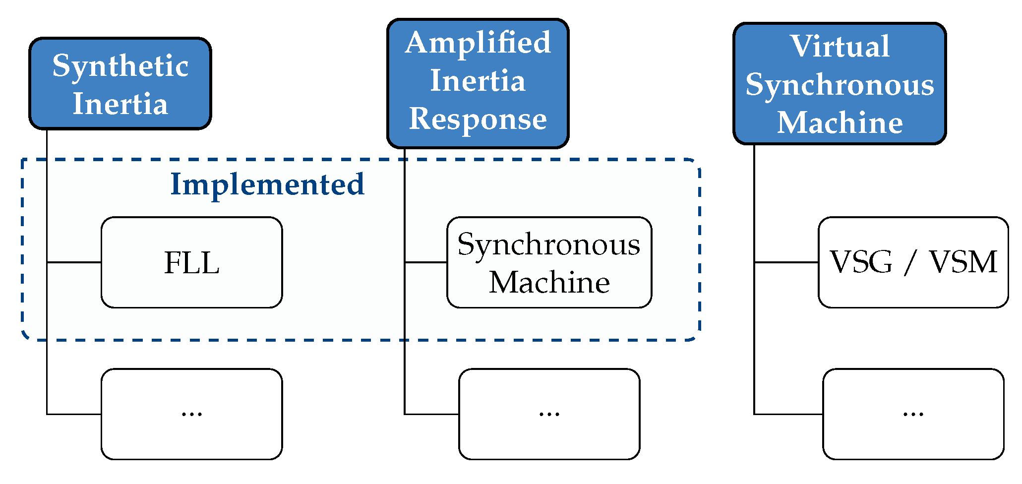
2. Method
The inertia enhancement methods considered in this paper fall into two categories. The first, where the common feature is that the grid frequency is differentiated numerically in real time, is called synthetic inertia (SI). The implementation is described in
Section 2.1, and will be referred to as
. This synthetic inertia method is characterized by the way that the frequency derivative is found, as a by-product of the FLL itself. Other methods can be achieved by filtering the frequency found by the FLL, but these methods are not implemented in this paper.
The second category, where the inertial response of a physical electrical machine is amplified, is denoted as the amplified inertia response (AIR). The acronym EI will also be used here to refer to our specific implementation, cf.
Section 2.2 below. Also within AIR, we consider two implementations, but since they differ only with respect to a choice of filter, we will neither consider them as different methods, nor introduce a distinguishing notation. The possible alternatives are shown in
Figure 1.
The remaining parts of
Section 2 touch upon phenomena relevant for evaluations and comparisons of the considered methods.
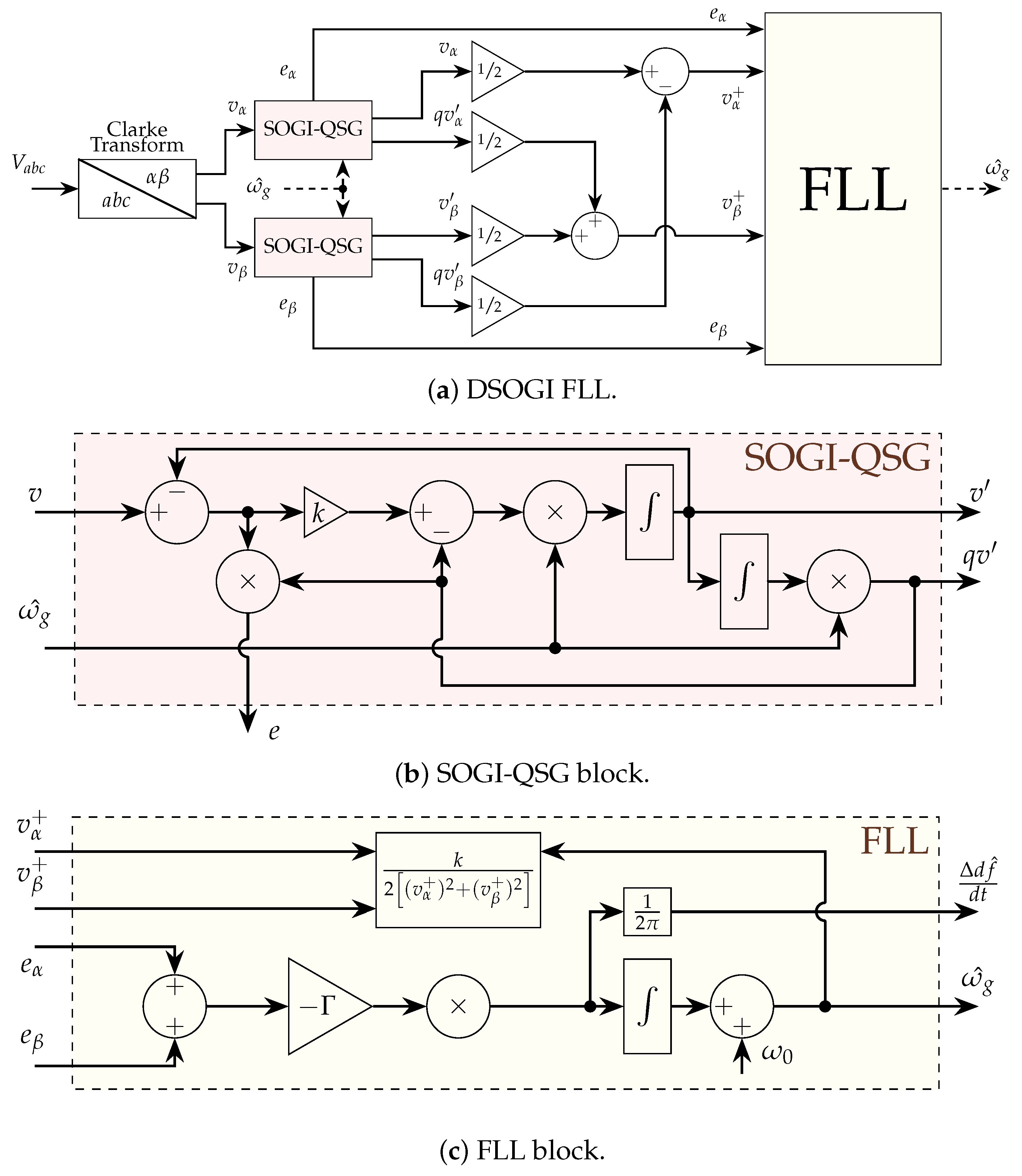
2.1. Implementation of Synthetic Inertia
The synthetic inertia system in
Figure 2 is based on a numerical differential calculation of the estimated grid frequency, which is linearly amplified to give an active power output reference to the energy storage system. Grid voltages are measured and a frequency-locked loop (FLL) extracts the frequency. Filters can be applied and the frequency derivative is calculated numerically. In the experimental implementation, we used a supercapacitor as energy storage for the inverter since we expect many cycles of absorbed and ejected power.
If a frequency derivative is calculated, the power output can be defined as
where
can be chosen depending in on the energy storage size and rating of the hardware. The method for estimating the grid frequency derivative
is described in
Section 2.1.
The inertial response from a synchronous machine (SM) comes from changing its speed as the grid frequency changes and the stator and rotor magnetomotive force (MMF) will have different speeds inside the SM. The machine can be a motor or a generator. The inertial response of a generator can be calculated from the change in rotational energy that the change in rotational speed will imply, as in
where
is the number of pole pairs of generator
i. This equation assumes a direct coupling between the grid frequency and the rotational speed, i.e., rotor angle oscillations are neglected. The power of the SM is measured by sampling the voltage and current at the SM terminals, and this signal can be sent to the inverter.
Frequency-Locked Loop Derivative Estimation
The frequency-locked loop (FLL) synthetic inertia implementation is based on the Double Second-Order Generalized Integrator Quadrature Signal Generator (DSOGI-QSG) FLL with an observer which has been discussed in [
31,
32]. The SOGI-QSG transfer function is described by (
3) and (
4), where (
3) acts as a band-pass filter
and (
4) acts as a low-pass filter
Here,
k is the SOGI-QSG filter gain constant,
is the FLL gain,
is the estimated grid angular frequency,
v is the input voltage signal from the Clark transform,
or
in this case, and
is the quadratic signal, always lagging
v by 90°. The structure of the FLL can be seen in
Figure 3 where the input to the integrator of the FLL gives the frequency derivative estimation which has been discussed in [
8]. This method will be referred to as
in the paper.
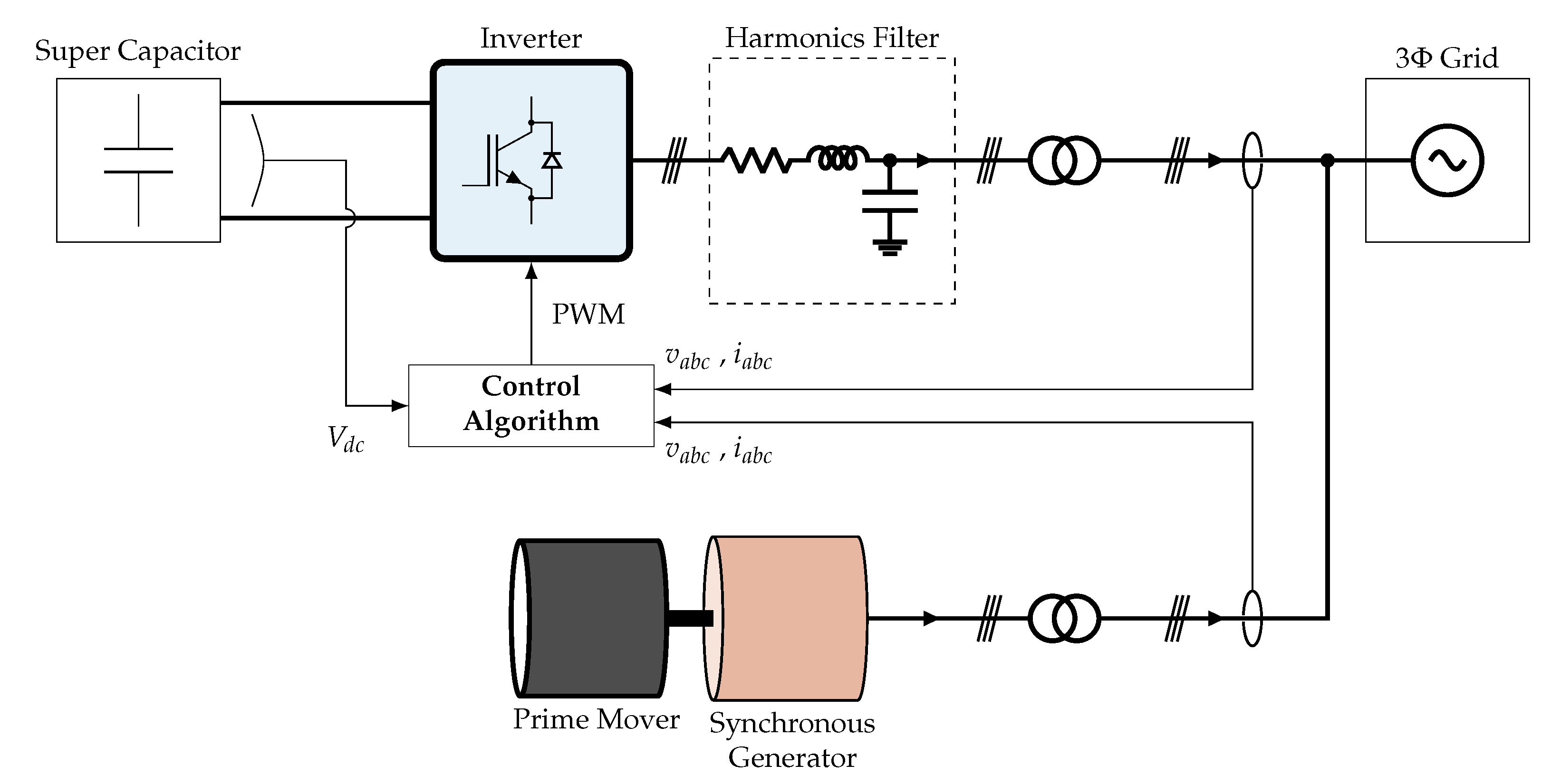
2.2. Implementation of Amplified Inertia Response
Figure 4 shows the proposed implementation of the amplified inertia response where an energy storage system is connected to the point of common coupling of the generator. The voltage and current are measured from the synchronous generator, and the power output is then calculated.
The inertial response given by the synchronous generator at a grid disturbance is shown in (
2). To avoid calculating the frequency derivative, the variation in output power is calculated and amplified as
, where
is the output power from the energy storage,
is the amplified inertia constant and
is the variation in output power from the synchronous machine. In the filter cases,
was filtered through two filters, designed to dampen the rotor angle oscillation, high-frequency measurement noise and the static power output from the generator. The first filter is described by
and is composed of a band-pass filter and a notch filter where the cutoff frequencies for the band-pass filter are defined by
and
. The notch filter frequencies are chosen by selecting the width of the rejected band with
and the center frequency with
.
The second filter is described by
and is composed of a low-pass filter used to remove higher electrical harmonics, a moving average filter to remove the average power, and a notch filter to dampen the rotor angle oscillation. The low-pass filter cutoff frequency is defined by
, and the average that is removed is computed by a moving average filter, specified by the time constant
T. This method, measurement and filtering together, will be referred to as
in the paper.
Rotor Angle Oscillations
The amplified inertia response method suffers from a drawback due to the fact that the inertial response,
, is the result of an altered load angle of the generator. The power output from a generator is governed by
where
U is the terminal voltage,
E the internal voltage,
the synchronous reactance and
the load angle.
We start with the so-called swing equation, which governs the relation between the power balance on the grid and the inertial response from SMs:
where
is the lumped generator power and
is the electrical power consumed by all loads, which include inertial response from the loads. For each generator
i,
is the total polar moment of inertia of the generator in kg m2,
is the mechanical angular speed and
is the electrical frequency in Hz. Damping and voltage and frequency dependence can be considered included in
, and
.
Rewriting the swing Equation (
8), using Equation (
7), we obtain a second-order differential equation resembling the harmonic oscillator
where
the mechanical torque,
tangential air gap magnetic stiffness and
the damping. One solution, depending on the relations between parameters, is a damped harmonic oscillation.
Typically, these rotor angle oscillations lie in a frequency range of 1 – 2 Hz. This means that a changed grid frequency will trigger a change in the rotor angle and also a rotor angle oscillation and a subsequent power response, which contains both the desired inertial power response and the oscillatory response, which is undesirable to amplify.
Rotor angle oscillations are dampened by damper windings on the rotor and partly by power system stabilizers acting on the field current. A special generating unit could be constructed where the rotor angle oscillations are well separated in frequency from the desired inertial response, or extremely well damped. However, to reduce the impact of the rotor angle oscillation will also mask the true inertial response that we want to enhance.
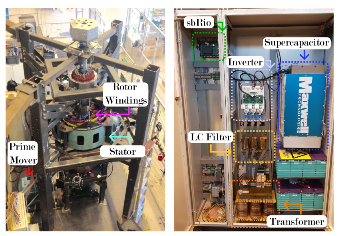
2.3. Microgrid Test Case
In order to compare the two synthetic inertia control strategies with the amplified inertia response, microgrid tests were performed. Some of the hardware used is shown in
Figure 5.
The benefit of using a microgrid in a lab is that the same load change can be tested several times with the different types of control strategies mentioned. The generator currents and voltages were saved with a sampling frequency of 10 kHz during the load disturbance, which was used for the generator inertia response,
and
calculation. The microgrid consisted of a 60 kVA synchronous generator, 50 kW fixed resistive load and a 6 kW variable resistive load. The prime mover to the generator was an asynchronous ABB motor with an ABB inverter which was controlled by a National Instruments cRIO. The cRIO used a PI controller to control the microgrid frequency, where the output was sent as a torque reference to the ABB inverter. The generator terminal voltage was controlled by a proportional controller, where the output was sent as a reference to the magnetization system. Further details about the small-scale lab setup can be found in [
33].
2.4. Nordic Grid Test Case
To compare the results from the synthetic inertia and the amplified inertia response control strategy in a large-scale grid, a National Instruments cRIO was connected to a 55 MVA synchronous hydropower generator to measure voltage and current. The measuring system was set to log voltage and current at the generator point of common coupling (PCC). The voltages and current were used for the generator inertia response, and calculation. When the grid frequency reached a predefined level, the cRIO saved 10 min before the disturbance, 10 min during the disturbance and 10 min after the disturbance with a sampling frequency of 5 kHz.
2.5. Comparing SI and AIR
In order to compare the main methods studied here, SI and AIR, we can carry out the following. The inertial response, Equation (
2), can be rewritten as
where all variables on the right-hand side are either known or measured and
can be calculated through the measured voltage and current. Thus, a direct comparison in
contribution on the same axis can be made, i.e., the estimated frequency derivative from the FLL filter can be compared with the frequency derivative calculated from the generator power output. The closer the virtual inertia method performs to the actual estimated frequency derivative
, the better it performs. The comparison will be divided into two parts: one on a short time scale to show the dominating behavior of the swing equation and a step change in the load where the FCR and automatic voltage regulator has not started to act, and one long term to show the influence of rotor angle oscillation.
3. Results
In this section, the results of the amplified inertia response strategy are presented. The section is divided into two parts where the first part presents the results from the microgrid lab setup, and the second part shows the results from a full-scale synchronous generator connected to the Nordic grid. The phase voltages and currents from one generator in each experimental setup were measured and logged. The data was then imported into Matlab Simulink 2021a, where it was used for calculating the power, filtering, and estimating the grid frequency from the voltages and the frequency derivative. The results from the Matlab Simulink model were then used for comparison between the two control strategies.
Table 1 shows the cutoff frequencies and parameters used in the two test cases in
Section 2.3 and
Section 2.4. The FLL calculation uses well-known parameters from the literature [
34], while the band-pass and low-pass filters are calculated as described in (
5) and (
6), respectively.
3.1. Microgrid
During the test, the driving torque reference sent to the inverter driving the motor which rotates the synchronous generator was kept constant, and the voltage was controlled by a proportional controller which adjusted the magnetisation current to keep a constant voltage at the generator terminals. At
an additional resistive load was connected to the microgrid giving a step increase in total load followed by a frequency drop on the grid. The results from the experiments showed that the voltage did not change during the load change. The grid frequency, generator power output, estimated frequency derivative from
and
system are shown in
Figure 6 and
Figure 7. The filter parameters used are shown in
Table 1.
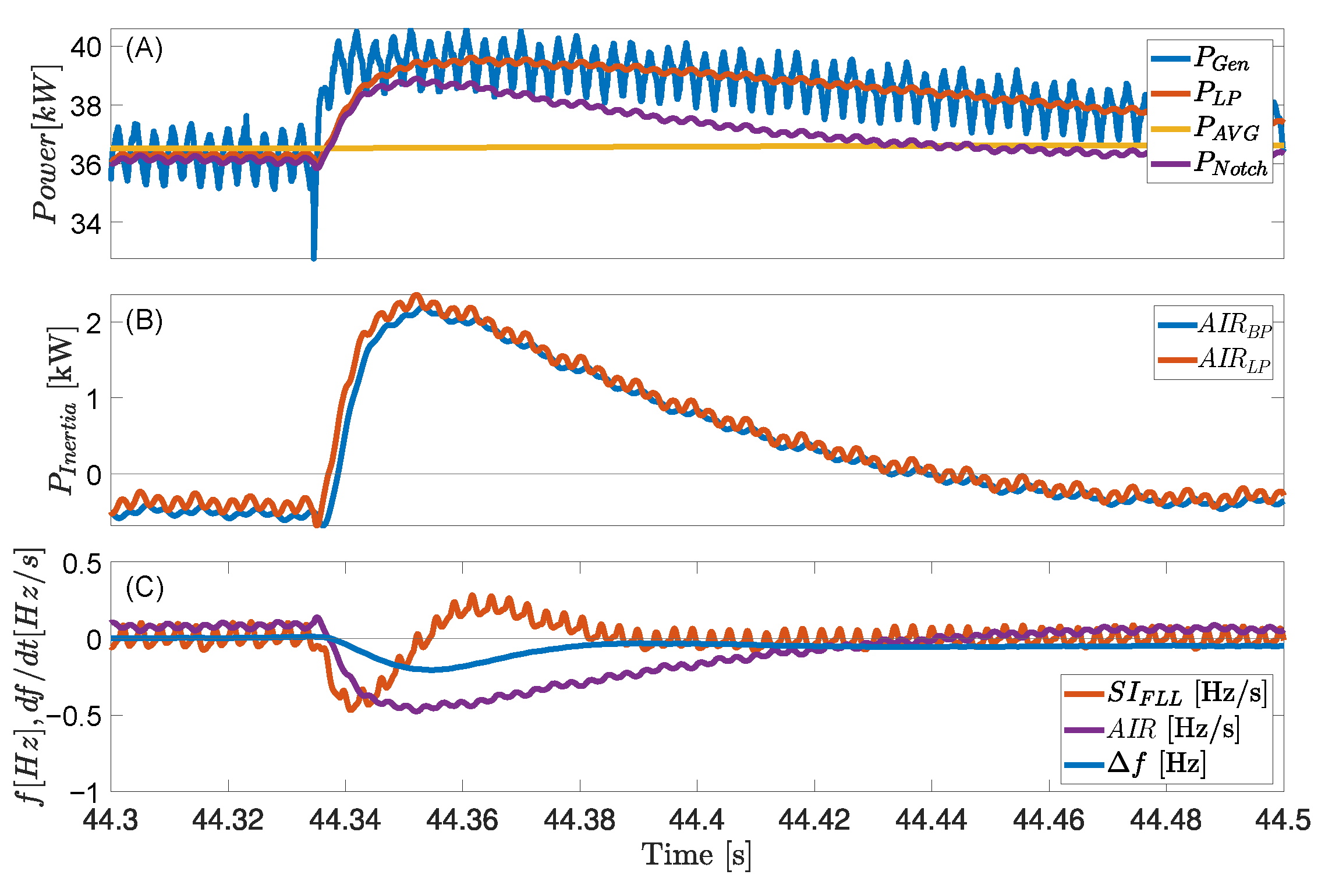
Figure 6A shows the electrical power response of the generator during the stepped load increase, corresponding to 0.11 p.u., and the subsequent rotor angle oscillation with three filters: low-pass, notch and a moving average.
Figure 6B shows the change in output power with two different filters. The low-pass, high-pass and moving average filter cutoff frequencies were chosen by trial and error in order to reduce the noise as much as possible. The low-pass filter is used to reduce high-frequency noise from measurements and voltage harmonics, and the high-pass filter is used to exclude the constant power from the generator. The FLL derivative estimation is filtered through a low-pass filter to reduce the high-frequency noise. It can be seen that
and
power continues to increase instead of returning back to zero. Both filters start to flatten out at 46 s; the new steady state is due to the increased power output from the generator to compensate for the increased load and long filter times causing the filtered power not directly returning to zero. A comparison between the methods is shown in
Figure 6C, where
has been chosen for the frequency derivative comparison due to its faster initial response.
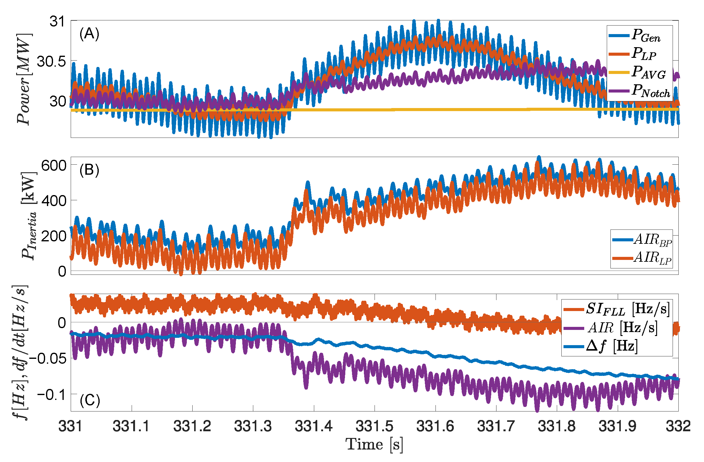
Figure 7 shows a zoomed-in part of
Figure 6. In
Figure 7A, it can be seen that the filtered step response is smoothed out compared to the unfiltered calculated power. The difference between
and
can be seen more clearly now, and the initial response from the
filter in
Figure 6B can be roughly estimated to be around 1.6 ms faster. The estimated derivative from the
gives a faster response than the alternative, and follows the frequency behavior. The steady-state power output from the generator was analyzed through an FFT where it could be seen that the rotor angle oscillation frequency was
Hz. The rotor angle oscillation in
Figure 6A was filtered out with a notch filter with its central frequency placed at the rotor angle oscillation frequency.
3.2. Nordic Grid
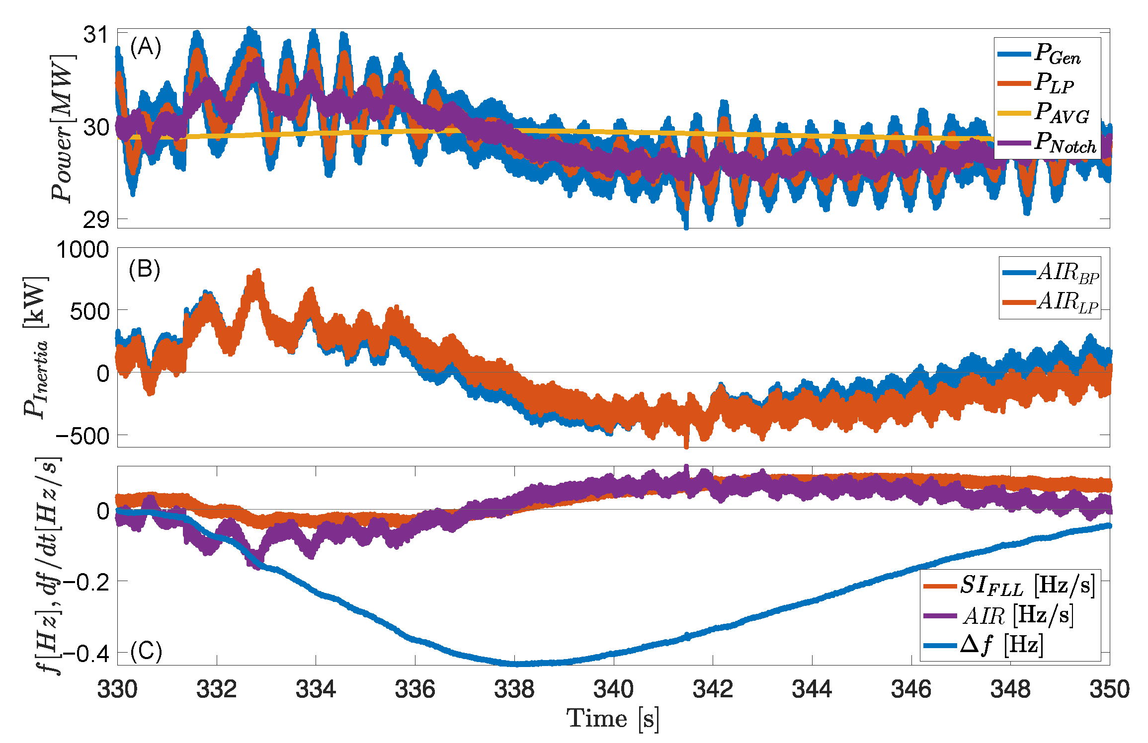
On a 55 MW hydropower generator, a system that continuously measures terminal voltage and current is installed. The system saves batches of data in 10-min slots. If an under-frequency or over-frequency event happens during the 10 min of data, it is stored, and otherwise discarded. The system has recorded several events over the years, of which one is analyzed here.
Figure 8 shows the generator electrical power response during an unknown grid disturbance causing an under-frequency of 400 mHz. On the time scale shown, the turbine active power reference is not changed.
Figure 8B shows the same filter applied as in
Figure 6B but with the filter parameters changed as shown in
Table 1.
Figure 8A shows the power output of the generator and the average power varying around
MW. It is seen that both
and
have very similar response times, with
returning to zero at a later time, which matches the frequency behavior better. As such, the
is chosen for the frequency derivative comparison. The estimated frequency derivative from
uses a low-pass filter due to its high content of noise.
Figure 9 shows a shorter time window of
Figure 8 during the grid disturbance for a comparison between the methods. In
Figure 9C it can be seen that the estimated derivative from the
is less noisy in terms of amplitude, and has higher-frequency noise, which can be easier to filter out. However, the
method does not show the same behavior as the
regarding the faster power response changes, and unlike the microgrid tests, it seems less responsive to frequency deviations.
4. Discussion
The differences we observe between
and
indicate that grid properties, such as the total inertia, power, and size of the disturbance matters significantly when choosing a control strategy. In the first case, in
Figure 6 in a microgrid system, the estimated derivative from the
is shown to be faster at detecting the frequency change, as the negative peak of the frequency derivative is around 11 ms delayed for the
. The drawback, however, is a larger noise content when compared to the amplified inertia response method. It can also be seen that the
derivative estimation follows the frequency better and returns to zero when the frequency has reached a new steady state, while the amplified inertia response maintains contribution to the grid as the steady state does not coincide with the nominal frequency. This behavior can be desirable, but this active power contribution could cause an overshoot of the frequency. The small rotor angle oscillation from the microgrid generator has been effectively dampened from the initial power output with the notch filter.
From the power output of the generator, it can be seen that when the generator reaches a new steady state, the moving average lags, which will cause the amplified inertia system to continue to deliver power to the grid even though the frequency derivative is zero, which could be reduced by decreasing the filter time.
In the case where the large generator is connected to the Nordic grid, it can be seen that the derivative estimation does not perform as well when the RoCoF is small due to its noise content and has to be filtered harder, which dampens the signal and does not give the initial power increase at the disturbance. Except for this dampened initial response, the remaining derivative estimation behaves very similarly to that seen with the amplified inertia response method, and no extra delay can be perceived.
The power output from the larger generator contains rotor angle oscillations with larger amplitudes compared to the microgrid generator, which can be seen in
Figure 8. This will have a larger impact on how severely the signal needs to be filtered before it can be used as a power reference to the inverter and energy storage system. The results show the importance of constructing a generator that minimizes the rotor angle oscillation, which will result in less filtering of the signal needed for the amplified inertia response.
Our results indicate that the amplified inertia method can work adequately in both scenarios, though it is outperformed in speed by microgrids. In larger grids, the amplified inertia response method is generally faster than the inertia calculation, but introduces more noise. Further, the level of complexity of implementing the different methods should be taken into consideration. The solution has the least computational requirements, as power can be estimated through voltage and current measurements, whilst the filter has higher real-time computational requirements. These extra requirements, however, can be overlooked as they are inherent to the synchronization method. This will affect the choice of computational hardware and energy storage. For a microgrid, a faster controller is needed, which can treat larger datasets with low latency, and an energy storage system, which can change its power output accordingly with low latency. In a large grid, the expected computational requirements tend to be lower due to the slower RoCoF, which in general means calculations do not need to be performed as fast.
This will result in a grid where the system can be used, and the problems with accurate frequency estimation and differentiation of the grid frequency can be avoided. The system will instead be dependent on a well-designed synchronous generator and thereby limit the places where energy storage can be placed.
5. Conclusions
The implementation and evaluation of a new approach for delivering synthetic inertia have been shown, based on enhancing the inertial response from a synchronous generator. It has been shown that using the power output from a synchronous machine makes it possible to amplify the power response during a frequency disturbance while avoiding estimating the grid frequency and differentiating it. The proposed amplified inertia response system has been compared to another synthetic inertia system based on the inherent frequency derivative calculated by the FLL. The amplified inertia response system has been shown to perform well in terms of time delay and and amplitude. For the microgrid tests, the proposed model displays reduced noise, albeit with reduced response speed. It also displays a different steady-state condition in which a new equilibrium point is given if the grid does not fully recover from a fault event. This steady-state condition implies that with the amplified inertia response method, support to the grid would still be provided if the system settles at a lower frequency than nominal. For the tests synchronized with the Nordic grid, on the other hand, the amplified inertia method appears more responsive than the FLL method, but with a significant increase in noise. This responsiveness, however, is challenging to estimate as frequency deviations are very low while grid-connected. Thus, it is shown that the investigated method operates with the desired characteristics for grid support, and successfully bypasses the usual process of finding the frequency derivative. However, it should be noted that rotor angle oscillation does impact the quality of the delivered energy and thus requires filtering.
Author Contributions
Conceptualization, M.F., P.N. and U.L.; methodology, M.F. and U.L.; software, M.F. and U.L.; validation, M.F. and V.M.d.A.; formal analysis, M.F., V.M.d.A. and U.L.; investigation, M.F., V.M.d.A., P.N. and U.L.; resources, U.L.; data curation, M.F. and U.L.; writing—original draft preparation, M.F., V.M.d.A., P.N. and U.L.; writing—review and editing, V.M.d.A. and U.L.; visualization, M.F., V.M.d.A. and U.L.; supervision, U.L.; project administration, U.L.; funding acquisition, U.L. All authors have read and agreed to the published version of the manuscript.
Funding
The research presented here was carried out as a part of “Swedish Centre for Sustainable Hydropower—SVC”. Available online:
svc.energiforsk.se (accessed on 10 July 2025).
Data Availability Statement
The raw data supporting the conclusions of this article will be made available by the authors on request.
Conflicts of Interest
Author Per Norrlund is employed by the company Vattenfall AB. The remaining authors declare that the research was conducted in the absence of any commercial or financial relationships that could be construed as potential conflicts of interest.
References
- Nordic Analysis Group. Systemutvecklingsplan 2018–2027. 2021. Available online: https://www.svk.se/siteassets/om-oss/rapporter/2018/svenska-kraftnat-system-development-plan-2018-2027.pdf (accessed on 10 July 2025).
- Dahlborg, E.; Norrlund, P.; Saarinen, L.; Lundin, U. Improving frequency control from Kaplan turbines to fulfill grid codes. In Proceedings of the HYDRO, Porto, Portugal, 14–16 October 2019; Aqua Media International Ltd.: Wallington, UK, 2019. [Google Scholar]
- Driesen, J.; Visscher, K. Virtual synchronous generators. In Proceedings of the 2008 IEEE Power and Energy Society General Meeting—Conversion and Delivery of Electrical Energy in the 21st Century, Pittsburgh, PA, USA, 20–24 July 2008; pp. 1–3. [Google Scholar] [CrossRef]
- Bevrani, H.; Ise, T.; Miura, Y. Virtual synchronous generators: A survey and new perspectives. Int. J. Electr. Power Energy Syst. 2014, 54, 244–254. [Google Scholar] [CrossRef]
- Citro, C.; Al-Numay, M.; Siano, P. Extensive assessment of virtual synchronous generators in intentional island mode. Int. J. Electr. Power Energy Syst. 2024, 157, 109853. [Google Scholar] [CrossRef]
- Badrudeen, T.U.; Nwulu, N.I.; Gbadamosi, S.L. Low-inertia control of a large-scale renewable energy penetration in power grids: A systematic review with taxonomy and bibliometric analysis. Energy Strategy Rev. 2024, 52, 101337. [Google Scholar] [CrossRef]
- Hasan, A.K.; Haque, M.H.; Mahfuzul Aziz, S. Enhancing Frequency Response Characteristics of Low Inertia Power Systems Using Battery Energy Storage. IEEE Access 2024, 12, 116861–116874. [Google Scholar] [CrossRef]
- Fang, J.; Zhang, R.; Li, H.; Tang, Y. Frequency Derivative-based Inertia Enhancement by Grid-Connected Power Converters with a Frequency-Locked-Loop. IEEE Trans. Smart Grid 2018, 10, 4918–4927. [Google Scholar] [CrossRef]
- Shi, R.; Wang, G.; Zhang, L.; Yu, Y.; Zhang, Y.; Zhang, X. An Enhanced Virtual Inertia Control Strategy Based on an Improved SOGI-FLL Scheme for Energy Storage Converters. In Proceedings of the 2021 IEEE 4th International Electrical and Energy Conference (CIEEC), Wuhan, China, 28–30 May 2021; pp. 1–6. [Google Scholar] [CrossRef]
- Bootha, D.; Beukes, J. Analysis of Phasor Measurement Strategies for application in synthetic inertia response. In Proceedings of the 2024 32nd Southern African Universities Power Engineering Conference (SAUPEC), Cape Town, South Africa, 24–26 January 2024; pp. 1–6. [Google Scholar] [CrossRef]
- Aljarrah, R.; Fawaz, B.B.; Salem, Q.; Karimi, M.; Marzooghi, H.; Azizipanah-Abarghooee, R. Issues and Challenges of Grid-Following Converters Interfacing Renewable Energy Sources in Low Inertia Systems: A Review. IEEE Access 2024, 12, 5534–5561. [Google Scholar] [CrossRef]
- Li, L.; Zhu, D.; Hu, J.; Lin, L.; Zou, X.; Kang, Y. Fast Inertial Response of PMSG-Based Wind Turbines with Optimized Frequency-Locked Loop. IEEE Trans. Power Electron. 2025, 40, 2697–2701. [Google Scholar] [CrossRef]
- Hajiakbari Fini, M.; Hamedani Golshan, M.E.; Martí, J.R.; Ketabi, A. Determining the Required Frequency Control Reserve and Capacity and Location of Synchronous and Virtual Inertial Resources. IEEE Trans. Sustain. Energy 2023, 14, 27–38. [Google Scholar] [CrossRef]
- Fang, J.; Li, H.; Tang, Y.; Blaabjerg, F. Distributed Power System Virtual Inertia Implemented by Grid-Connected Power Converters. IEEE Trans. Power Electron. 2018, 33, 8488–8499. [Google Scholar] [CrossRef]
- Rouzbehi, K.; Zhu, J.; Zhang, W.; Gharehpetian, G.B.; Luna, A.; Rodriguez, P. Generalized voltage droop control with inertia mimicry capability-step towards automation of multi-terminal HVDC grids. In Proceedings of the International Conference on Renewable Energy Research and Applications, ICRERA, Palermo, Italy, 22–25 November 2015; Volume 5, pp. 1556–1561. [Google Scholar] [CrossRef]
- Wu, H.; Ruan, X.; Yang, D.; Chen, X.; Zhao, W.; Lv, Z.; Zhong, Q.C. Small-Signal Modeling and Parameters Design for Virtual Synchronous Generators. IEEE Trans. Ind. Electron. 2016, 63, 4292–4303. [Google Scholar] [CrossRef]
- Serban, I.; Ion, C.P. Microgrid control based on a grid-forming inverter operating as virtual synchronous generator with enhanced dynamic response capability. Int. J. Electr. Power Energy Syst. 2017, 89, 94–105. [Google Scholar] [CrossRef]
- Sun, D.; Liu, H.; Gao, S.; Wu, L.; Song, P.; Wang, X. Comparison of Different Virtual Inertia Control Methods for Inverter-based Generators. J. Mod. Power Syst. Clean Energy 2020, 8, 768–777. [Google Scholar] [CrossRef]
- Fang, J.; Tang, Y.; Li, H.; Li, X. A Battery/Ultracapacitor Hybrid Energy Storage System for Implementing the Power Management of Virtual Synchronous Generators. IEEE Trans. Power Electron. 2018, 33, 2820–2824. [Google Scholar] [CrossRef]
- Liu, J.; Yang, D.; Yao, W.; Fang, R.; Zhao, H.; Wang, B. PV-Based Virtual Synchronous Generator with Variable Inertia to Enhance Power System Transient Stability Utilizing the Energy Storage System. Prot. Control Mod. Power Syst. 2017, 2, 1–8. [Google Scholar] [CrossRef]
- Stiger, A.; Rivas, R.A.; Halonen, M. Synchronous Condensers Contribution to Inertia and Short Circuit Current in Cooperation with STATCOM. In Proceedings of the 2019 IEEE PES GTD Grand International Conference and Exposition Asia, GTD Asia 2019, Bangkok, Thailand, 19–23 March 2019; pp. 955–959. [Google Scholar] [CrossRef]
- Li, H.; Nie, C.; Wang, F. Grid Strengthening IBR: An Inverter-Based Resource Enhanced by a Co-Located Synchronous Condenser for High Overcurrent Capability. IEEE Open J. Power Electron. 2022, 3, 535–548. [Google Scholar] [CrossRef]
- Wang, Y.; Wang, L.; Jiang, Q. Impact of Synchronous Condenser on Sub/Super-Synchronous Oscillations in Wind Farms. IEEE Trans. Power Deliv. 2021, 36, 2075–2084. [Google Scholar] [CrossRef]
- Nguyen, H.T.; Yang, G.; Nielsen, A.H.; Jensen, P.H. Combination of Synchronous Condenser and Synthetic Inertia for Frequency Stability Enhancement in Low-Inertia Systems. IEEE Trans. Sustain. Energy 2019, 10, 997–1005. [Google Scholar] [CrossRef]
- Majuder, R.; Johansson, B.N. Synthetic Inertia Provided Based on Synchronous Machine. International Patent Application No. PCT/EP2018/073469, International Publication Data No. WO 2020/043306 A1. GB Patent Application No. 2590271 B, 20 July 2022. [Google Scholar]
- Wang, J.; Huang, W.; Tai, N.; Yu, M.; Li, R.; Zhang, Y. A Bidirectional Virtual Inertia Control Strategy for the Interconnected Converter of Standalone AC/DC Hybrid Microgrids. IEEE Trans. Power Syst. 2024, 39, 745–754. [Google Scholar] [CrossRef]
- Zhang, C.; Dou, X.; Zhang, Z.; Lou, G.; Yang, F.; Li, G. Inertia-Enhanced Distributed Voltage and Frequency Control of Low-Inertia Microgrids. IEEE Trans. Power Syst. 2021, 36, 4270–4280. [Google Scholar] [CrossRef]
- Kerdphol, T.; Rahman, F.S.; Watanabe, M.; Mitani, Y.; Turschner, D.; Beck, H.P. Enhanced Virtual Inertia Control Based on Derivative Technique to Emulate Simultaneous Inertia and Damping Properties for Microgrid Frequency Regulation. IEEE Access 2019, 7, 14422–14433. [Google Scholar] [CrossRef]
- Kerdphol, T.; Rahman, F.S.; Watanabe, M.; Mitani, Y. Robust Virtual Inertia Control of a Low Inertia Microgrid Considering Frequency Measurement Effects. IEEE Access 2019, 7, 57550–57560. [Google Scholar] [CrossRef]
- Mishra, S.; Ranjan Sahu, P.; Chandra Prusty, R.; Panda, S.; Selim Ustun, T.; Onen, A. Application of Enhanced Self-Adaptive Virtual Inertia Control for Efficient Frequency Control of Renewable Energy-Based Microgrid System Integrated with Electric Vehicles. IEEE Access 2025, 13, 43520–43531. [Google Scholar] [CrossRef]
- Ahmed, H.; Benbouzid, M. Adaptive Observer-Based Frequency-Locked Loops for Renewable Energy Systems: A Comparative Analysis. In Proceedings of the IECON Proceedings (Industrial Electronics Conference), Virtual, 18–21 October 2020; pp. 4941–4946. [Google Scholar] [CrossRef]
- Ma, W.; Ouyang, S.; Xu, W. Improved frequency-locked loop based synchronization method for three-phase grid-connected inverter under unbalanced and distorted grid conditions. Energies 2019, 12, 1023. [Google Scholar] [CrossRef]
- Fregelius, M.; Lundin, U. Hardware Implementation of A Synthetic Inertia System for Grid Stability. In Proceedings of the 2019 8th International Conference on Renewable Energy Research and Applications (ICRERA), Rio de Janeiro, Brazil, 3–6 November 2019; pp. 186–190. [Google Scholar] [CrossRef]
- Teodorescu, R.; Liserre, M.; Rodriguez, P. Grid Converters for Photovoltaic and Wind Power Systems; John Wiley & Sons: Hoboken, NJ, USA, 2011. [Google Scholar]
| Disclaimer/Publisher’s Note: The statements, opinions and data contained in all publications are solely those of the individual author(s) and contributor(s) and not of MDPI and/or the editor(s). MDPI and/or the editor(s) disclaim responsibility for any injury to people or property resulting from any ideas, methods, instructions or products referred to in the content. |
© 2025 by the authors. Licensee MDPI, Basel, Switzerland. This article is an open access article distributed under the terms and conditions of the Creative Commons Attribution (CC BY) license (https://creativecommons.org/licenses/by/4.0/).


