1. Introduction
1.1. Background
According to the IEA Global Energy Review 2025, renewables and nuclear power contributed 80% of the global growth in electricity generation in 2024. Together, they accounted for 40% of total global power output. Renewable energy has become one of the most significant energy resources in contemporary society.
The large-scale and efficient utilization of renewable energy serves as an effective means to achieve carbon peaking and carbon neutrality goals. In large-scale renewable energy utilization systems, there still exists the mismatch between energy supply and demand at the current stage [
1]. Introducing energy storage systems in renewable energy systems can stabilize energy fluctuations and address the spatiotemporal mismatch between energy supply and demand.
Among energy storage technologies, thermal storage stands out for its cost efficiency and longevity. Current Chinese market data (2025) reveal stark contrasts: Battery-grade lithium carbonate costs CNY 60,200/ton (May), while binary molten salt is priced at CNY 5000/ton (February). At the system level, LiFePO4 battery packs require 0.32–0.44 CNY/Wh, whereas seasonal water pit thermal storage operates at just 300–500 CNY/m3—equivalent to a remarkably low 0.005–0.009 CNY/Wh.
Thermal energy storage is appropriate for large-capacity and large-scale energy storage, capable of fulfilling the application requirements such as large-scale power peak shaving, multi-energy complementarity, and efficient utilization. Moreover, it possesses the potential for large-scale commercial promotion [
2]. Consequently, the application of high-efficiency heat storage technology in large-scale industrial scenarios is of substantial practical significance [
3].
According to the energy storage mechanism, thermal energy storage (TES) systems can be divided into three types, namely sensible heat storage, latent heat storage, and thermochemical heat storage. Due to their high latent heat [
4] and constant charging–discharging temperature [
5], phase change materials (PCMs) are recognized as promising thermal energy storage materials. PCMs are widely used not only in solar energy systems and industrial waste heat recovery systems but also in food packaging, clothing, and in green building fields [
6].
Given the current technological backdrop, latent heat storage can be segmented into two main application directions: short-term heat storage application and long-term heat storage application.
1.2. Short-Term Heat Storage
In a short-term heat storage system, adding phase change heat storage materials to enhance its thermal performance is the main PCM heat storage application. Huang et al. [
7] added PCMs into a 0.3 m
3 water tank in a conventional 35 °C /45 °C heating system. The results showed that when the sodium acetate trihydrate (SAT) volume ratio was 67–78%, the heat storage capacity was increased from 1.72 GJ to 2.25 GJ, and the solar fraction of the short-term heat storage system was increased by about 30%. Laasri et al. [
8] evaluated the heat storage performance of hollow concrete blocks integrated with PCMs under semi-arid climate conditions in Morocco. The results showed that, after adding PCMs, the cooling energy consumption was reduced by 20%, and the temperature fluctuation was reduced by 2.3 °C. However, due to the supercooling, the latent heat potential of the PCMs was underutilized, as only 43% of the latent heat capacity was utilized.
Enhancing heat transfer is an important research direction. Rashid et al. [
9] investigated the influence of different fin arrangements on enhancing the melting of paraffin wax (RT42). The results showed that for a 50 × 50 mm square PCM cell, when the operating temperature was 323 K, the melting time could be shortened from 270 min to 210 min, whereas the melting time could be shortened from 270 min to 180 min when adding undulated fins. It was concluded that in short-term heat storage, adding fins could enhance the melting process effectively and that the enhancement of complex fins was better than that of straight rectangular fins. Kiyak et al. [
10] analyzed the effect of geometrical configurations on the melting and solidification behaviors of PCMs (RT42). The results showed that for charge, heating from the side offered the quickest melting performance. The melting rate of side heating was 240% higher than that of bottom heating. For solidification, the solidification rate of top cooling was 15.4% faster than that of bottom cooling.
Novel PCM development is also a key research field. Husniatul et al. [
11] proposed a new PCM composite of polyethylene glycol (PEG) 400 and lauric acid (LA). The phase change temperature was 30–40 °C, the latent heat was 181.5 J/g, and the PCMs showed good thermal stability after 1000 thermal cycles. Hosseini et al. [
12] investigated the enhancement of surface modified nanoparticles on the thermal properties of paraffin. The results showed that the graphene oxide (GO) nanoparticles modified with ethoxytrimethylsilane (ETMS) was a good additive for paraffin. After adding the modified GO (MGO) nanoparticles (no more than 1%), the melting enthalpy was increased by 0–8%, the initial degradation temperature was increased by about 22–26 °C, and the thermal conductivity was increased by 13–39%.
1.3. Long-Term Heat Storage
Utilizing PCMs for long-term heat storage has emerged as a novel research focus. To realize long-term heat storage, PCMs should have stable supercooling characteristics, meaning that the latent heat can be kept in a stable supercooled state for a long time and that precise control of the heat release process is allowed whenever it is necessary. If PCMs are kept in stable supercooling at room temperature, the heat loss will be minimized by decreasing the temperature difference between the storage device and the surroundings. The release of heat from stable supercooled PCMs is solely dependent on the initiation of solidification and remains decoupled from temperature conditions.
One advantage of long-term heat storage utilizing stable supercooling is that the latent heat can be kept at room temperature for a long period. For 5.5 L heat storage tanks with SAT-based PCMs, 12 h heating with a temperature of 80 °C was enough to achieve the supercooled state [
13,
14]. The achieved supercooling was not influenced by room temperature fluctuation. Before triggering solidification, the supercooling was kept for many days. In the experiments at the Technical University of Denmark, the stable supercooling of SAT-based PCMs in a small tank was successfully kept for more than two years [
15].
The second advantage of long-term heat storage utilizing stable supercooling is that the supercooling is stable enough and not influenced by heating–cooling cycles. When stable supercooling is achieved, PCMs in liquid form can also be used as short-term heat storage for many heating–cooling cycles in a similar way as a hot water tank. In experiment [
16], the heat storage with SAT-based PCMs could achieve the stable supercooling state, and the supercooling state could be kept after 20 thermal cycles as a sensible heat store, making it a good short-term heat storage device. This is the foundation of a flexible heat storage device combining short-term and long-term heat storage capabilities.
The third advantage is that the long-term heat loss is relatively low. The sensible heat store can be used first, and then the latent heat can be kept at room temperature. In this condition, there is almost no further sensible heat loss before the release of the latent heat. In a real experiment, after a long period for a 4 × 200 kg PCM heat storage system [
17], about 80% of the conserved heat of fusion was released and utilized during discharge, meaning the heat loss was around 20%.
Achieving long-term heat storage using PCMs fundamentally relies on maintaining them in a metastable supercooled state. Our findings demonstrate that maintaining stable supercooling in PCMs hinges critically on three factors: minimizing particulate content within the PCMs, reducing the surface roughness of the containment vessels, and eliminating nucleation sites.
1.4. PCM Solidification
Latent heat release coincides with PCM crystallization. To undertake in-depth research and ameliorate the latent heat releasing characteristics of a particular PCM, it is of essence to disclose its solidification mechanism.
To reveal the solidification characteristics of a PCM, there are two major methods. One approach is to utilize the Scanning Electron Microscope (SEM) to elucidate its crystal structure and surface morphology. Another method is to employ the Optical Microscope (OM) to visualize the morphology of its crystal clusters and observe the growth process of these crystals.
Hua et al. [
18] investigated the effect of adding a nucleating agent and a thickening agent on decreasing the supercooling degree and on inhibiting phase separation. In their research, disodium hydrogen phosphate (DSP) was selected as the nucleating agent and xanthan gum was selected as the thickening agent. The SEM figures showed that the surface of DSP exhibited distinct porousness; therefore, it can be inferred that DSP had a stronger adsorption capacity for SAT and that it was easier to form a firm crystalline adsorbate on its surface. Ortac et al. [
19] added boron nitride–lead oxide nanoparticles into a crosslinked poly copolymer to increase thermal conductivity. The thermal conductivity of a 13 wt%BN-60.90 wt%PbO-26.10 wt%PS-PEG composite was determined to be 18.874 W/(m·K). The SEM figures showed that there were many cavities at the interactive interface of the BN–PbO nanoparticles and that the polymer chains were linked together. These properties are effective factors that improve heat transfer in thermally conductive polymer composites. Wang et al. [
20] added expanded graphite (EG) to increase the conductivity of a SAT-based PCM composite. The SEM figures showed that EG had a good layered and void structure and could be a good carrier for the composite. After adding 1.5 wt% EG, the conductivity of the composite was increased from 0.62 W/(m·K) to 1.1626 W/(m·K). After a 30-day experiment, the SEM figures showed that the copper, aluminum, and iron surfaces were all corroded by the composite and that there was no corrosion on the 304 stainless steel.
The optical microscope is generally used to observe and record the entire solidification and melting process of PCMs, providing more comprehensive information. Meanwhile, the crystal size and structure of PCMs can also be determined by OM figures.
Anirban et al. [
21] presented a novel in operando study to visually observe the crystallization process of zinc nitrate hexahydrate (ZNH) in real time. A 50 μm layer of PCM was observed by an optical microscope (Olympus BX-51). The OM figures showed that the additive interacted with the molten PCM to precipitate insoluble needle-like particles into the solution and that the ZNH nucleation started at some of the needle-like precipitated particles. Boland et al. [
22] investigated the effect of the emulsification process of the organic n-eicosane as a PCM in an aqueous solution of sodium dodecyl sulfate (SDBS) as a surfactant—which has been studied regarding the properties of the CaCO
3 microcapsules. The OM images showed a core–shell morphology, according to the emulsification process, and the mean size of the n-eicosane capsule was of the order of 5 μm. Angel-López et al. [
23] developed a novel, organic, solid–liquid PCM composite derived from methoxy polyethylene glycol (MPEG) and aromatic acyl chlorides (ACs). The crystalline morphology of these synthesized materials was examined by OM images, and the results showed that spherulites with Maltese cross extinction patterns were formed inside the PCM. Generally, the size of PCM was larger than the size of the precursors. For example, the mean size of the MPEG5000 precursor was about 2.0 mm, whereas the mean size of the PCM was 3.2–3.3 mm. Serrano et al. [
24] investigated the thermal performance of a shape-stabilized PCM developed from neopentyl glycol (NPG). The results showed that higher capillary forces could be obtained by decreasing the NPG crystal size. Moreover, the OM figures showed that the use of ball milling (grinding materials in a rotating container with balls) significantly decreased the NPG crystal size from 204.13 µm to 16.53 µm (91.9%).
The rapid formation of small crystals can provide more nucleation points and expedite crystallization, thereby enhancing the heat release capabilities of a PCM. Sun et al. [
25] developed a novel organic–inorganic eutectic PCM based on SAT and PEG. The OM images revealed that the addition of PEG preserved the original needle-shaped crystal morphology of SAT. After adding PEG, the PCM crystal size was decreased from 500–1000 µm to 200–500 µm. This was because the organic substance PEG, with a larger crystal size, was able to provide a framework for the inorganic hydrated salt SAT and to utilize its relatively high electronegativity to pair with the Na+ of the inorganic hydrated salt SAT, offering nucleation sites and reducing the interfacial energy, thereby facilitating the rapid generation of SAT crystals.
1.5. Aim and Scope
This study performs experiments to investigate the heat-releasing performance and the solidification mechanism of a SAT composite. During the experiment, the temperature changes and morphological changes of the SAT composite are recorded in totality. Two different solidification modes are observed, and the reasons influencing these solidification modes are analyzed. Further, the crystallization rate of supercooled SAT is determined. The results provide experimental references and a theoretical basis for enhancing latent heat release characteristics.
2. Methods
2.1. Materials and the Storage Unit
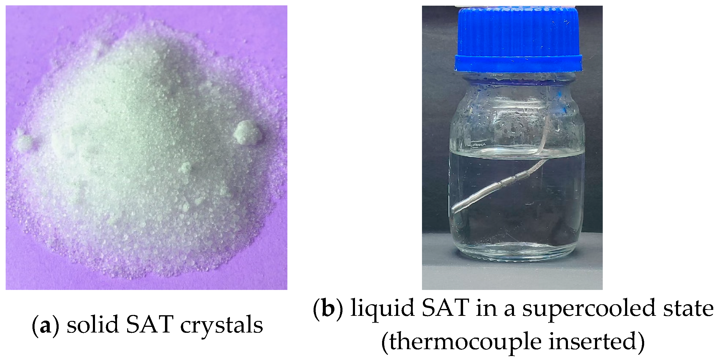
A PCM composite with stable supercooling was developed and utilized. In the composite, sodium acetate trihydrate (SAT) was the base material, and extra water and polymers were added as additives. The melting point of the PCM was between 53 and 58 °C, and the latent heat was in the range of 205–210 kJ/kg. The composite was tested for over 300 thermal cycles before utilization, and no phase separation occurred during testing, indicating good stability. The SAT crystals and the liquid SAT in a supercooled state are shown in
Figure 1. The thermal properties of SAT and the SAT-based PCM are shown in
Table 1.
SAT (NaCH
3COO·3H
2O, 60.3% sodium acetate, and 39.7% water) is an incongruently melting salt hydrate [
26]. The analytical pure SAT was purchased from Shanghai Aladdin Biochemical Technology Co., Ltd., (purity 99.995%, Shanghai, China). The theoretical melting point and the latent heat of SAT is 58 °C and 264 kJ/kg, respectively. The polymer materials were purchased from Sinopharm Chemical Reagent Co., Ltd., (AR purity, Shanghai, China).
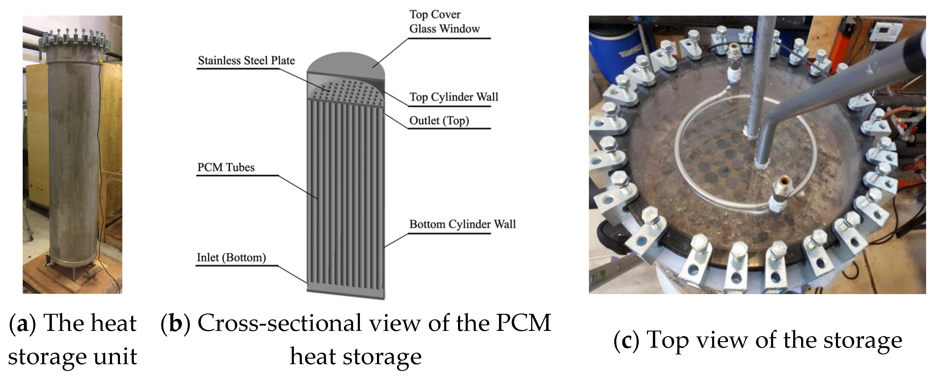
To investigate the thermal performance of a PCM in real utilization conditions, a heat storage unit filled with a PCM composite was manufactured (
Figure 2). The height of the storage was 1.7 m, and the outer diameter was 0.4 m (without insulation). A quantity of 112 tubes were mounted vertically inside the storage, each with a length of 1.52 m and an inner diameter of 0.0276 m. The tops of the tubes were fixed to a steel plate and opened to the volume above the plate. The inlet was located at the bottom of the storage, and the outlet was located at the top of the storage water volume (under the stainless steel plate). The top of the cylinder was made of glass to facilitate visual observation of the storage tank. For triggering the solidification of the supercooled PCM, a vertical pipe with a ball valve was mounted where SAT crystals could be inserted. Inside the heat storage, a total of 137.8 kg of the PCM was distributed across the 112 tubes and the upper header.
2.2. Measurement Techniques
To investigate the heat release characteristic, the PCM heat storage was tested in a macro charge–discharge testing system,
Figure 3 shows a diagram of the heat storage test rig. The testing system consisted of an electric heating element, a cooling unit, and a water pump. The cooling unit was connected to the central cooling system, providing a stable low-temperature cooling fluid.
A five-junction thermopile with an uncertainty of 0.1 K was used to measure the temperature difference between the inlet and the outlet of the heat transfer fluid. Brunata HGQ-1-R3 flow meters (Brunata A/S, Herlev, Denmark) with a maximum uncertainty of 2% (below class uncertainty: EN 1434) were used. Signals from the thermocouples and thermopiles were read via a National Instruments NI9214 card (National Instruments Corporation, Austin, TX, USA), and the flow meter was read signal via an NI9403 (National Instruments Corporation, Austin, TX, USA) card—both cards were connected to a CompactDAQ (National Instruments Corporation, Austin, TX, USA). Data were logged by a LabVIEW monitoring program with 1 min intervals (LabVIEW 2018). Ten thermocouples T1–T10 were placed on the outer surface of the cylindrical tank in good thermal contact with the tank wall and covered by the insulation.
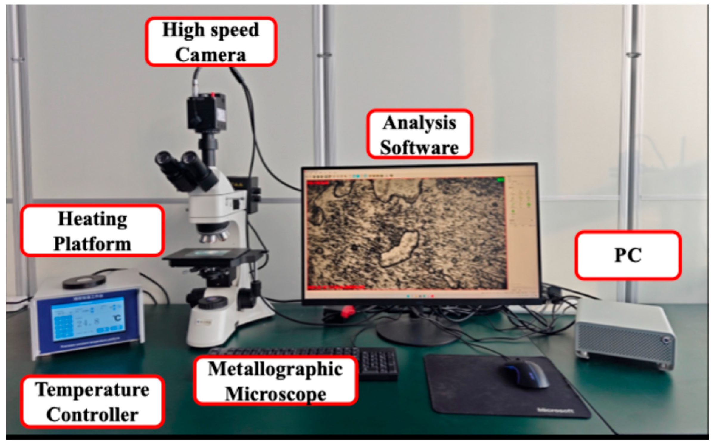
To investigate the crystallization characteristics, the PCM was observed and analyzed under a metallographic microscope (JP-55C, Beijing Caisi Technology Co., Ltd., Beijing, China) and a high-speed camera (JP-1600M3, Shenzhen Ausway Optical Instrument Co., Ltd., Shenzhen, China). The magnification power of the eyepiece was 5×, and the magnification power of the objective lenses changed from 1× to 80×. Due to the diameter of SAT crystals, it is not advisable to use a high magnification power. A heating platform with temperature controller (JP-600, Beijing Jingpu Technology Co., Ltd., Beijing, China) was used to provide different temperature environments. The power of the platform was 360 W, and the maximum heating temperature was 380 °C. The microscope–high-speed camera test system is shown in
Figure 4.
3. Results and Discussion
3.1. Self-Solidification in Heat Storage
3.1.1. Visualization of Self-Solidification
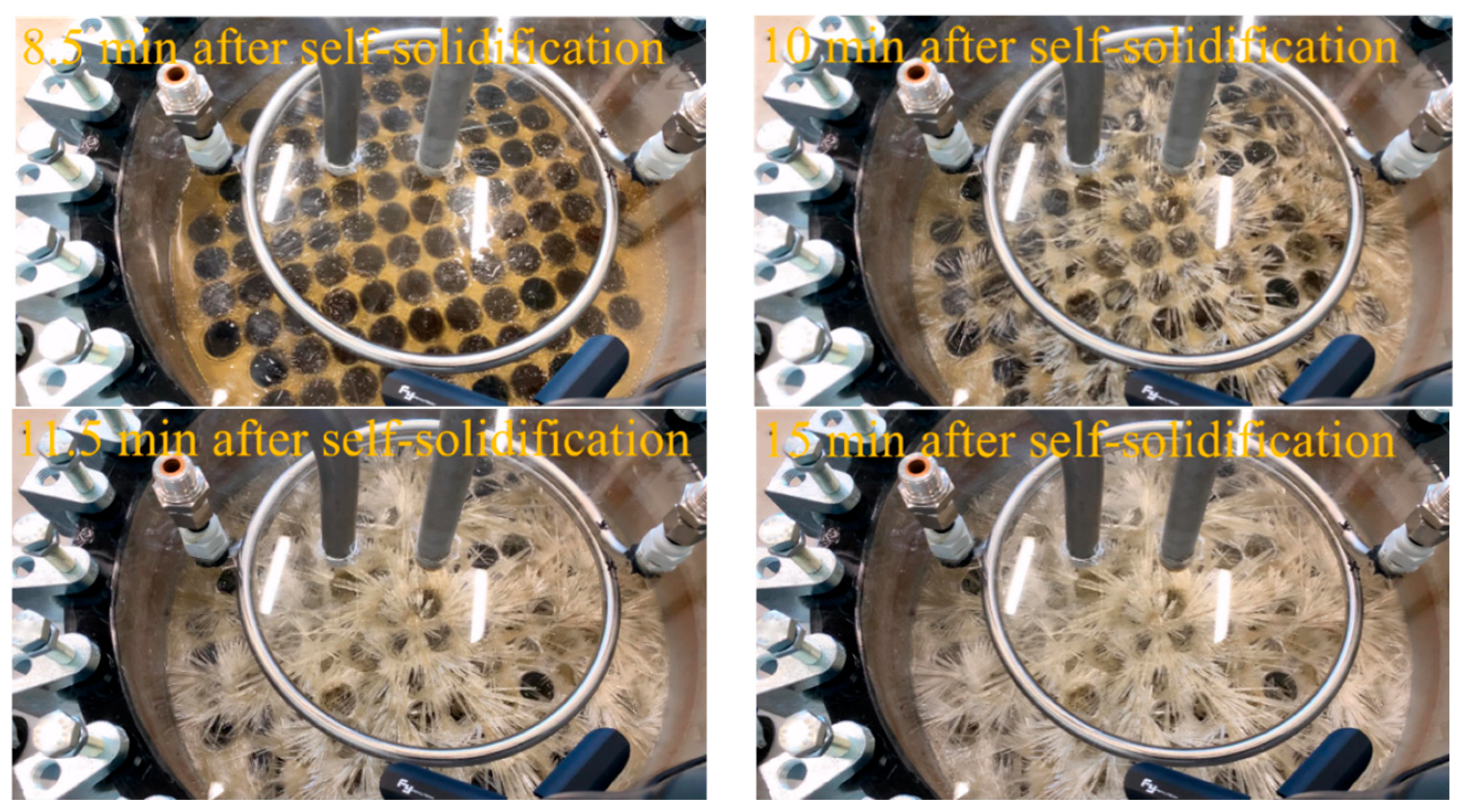
Photos of the PCM during the self-solidification process inside the heat storage device are shown in
Figure 5 and
Figure 6.
Figure 5 shows the first stage of self-solidification (0–8 min); the acicular cylinder crystal cannot be observed. This stage is called the incubation stage.
Figure 6 is the second stage of self-solidification (8–15 min); the acicular cylinder crystal can be obviously observed. This stage is called the growth stage.
In the first stage, the supercooled PCM is a yellowish liquid. Before self-solidification, the yellowish liquid is clear and transparent, and there are no crystals inside the liquid. When self-solidification begins, part of the liquid material becomes cloudy, and crystals start to form in the PCM (2 min after self-solidification,
Figure 5 red circle). As solidification continues, more cloudy areas appear dispersively. Due to the uniform nucleation–crystal growth process, in a certain time interval within each sub-region of the parent phase, the probability of crystallization is equal. The phenomenon of cloudy areas appearing in many places during self-solidification agrees with the classical crystal growth theory.
With the development of solidification, the height of the PCM liquid decreases due to the density difference between the solid and the liquid forms of the PCM. After 8 min of the start of self-solidification, tiny-sized PCM crystals are observed, and the second stage starts. In the second stage, the PCM crystals increase rapidly. The crystal morphology is thin and long. After 15 min, the crystal morphology is basically stabilized. As shown in
Figure 6, the PCM crystals formed by self-solidification are distributed dispersively, and the color of the solid PCM formed by self-solidification is milky yellow.
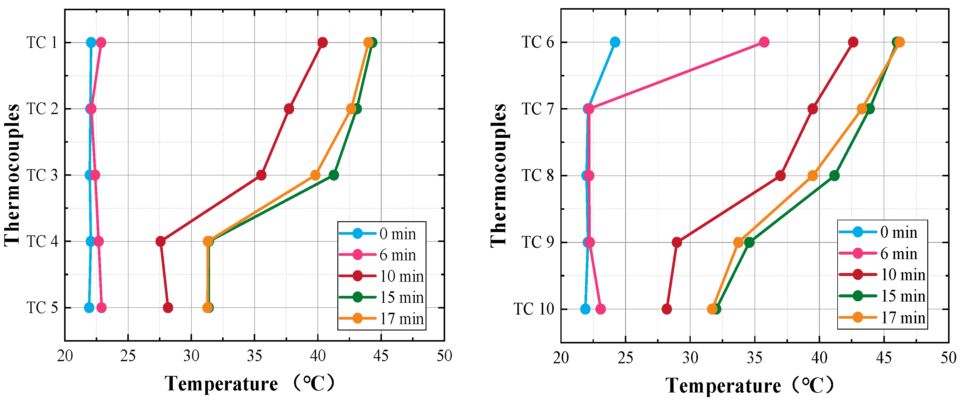
3.1.2. Surface Temperature in Self-Solidification
Figure 7 shows surface temperature of the heat storage after the beginning of self-solidification. From the figure, it can be observed that the surface temperature of the whole heat storage cooled down to about 22 °C before self-solidification occurred. It should be pointed out that the surface temperature is not the temperature of the liquid PCM inside the heat storage device. When self-solidification starts, the latent heat of PCM is released. The released latent heat is transferred from the PCM to the wall of the PCM tubes and then to the heat transfer fluid (HTF) outside the tubes. Consequently, the temperature of the HTF increases gradually. The container wall of the heat storage is heated by HTF, and then the wall temperature increases.
Thermocouples TC1–TC5 were placed on the inlet side wall of the heat storage, TC6–TC10 were placed on the outlet side wall of the heat storage. All thermocouples were covered with mineral wool insulation to reduce heat loss and to make the measurements more accurate.
As shown in
Figure 7, when self-solidification occurs, the temperature increase in the outlet side wall happens sooner than that in the inlet side wall. The first explanation is that the position of where self-solidification occurs is close to the outlet side wall, and thus, I released latent heat is transferred sooner to the outlet side wall. The second explanation is that due to the horizontal flow of HTF from inlet to outlet, the heated HTF flows to the outlet side wall preferentially, and thus, the outlet side wall is heated sooner than the inlet side wall.
After self-solidification, the surface temperature distribution of the heat storage is “upper-high, bottom-low”, which is to say that the temperatures of TC1 and TC6 are the highest and that the temperatures of TC5 and TC10 are the lowest. The first explanation is that the position of self-solidification occurs in the upper part of the heat storage. The second explanation is that with the flow of HTF from inlet to outlet, the HTF is heated from the bottom to the upper part of the heat storage. Therefore, higher temperatures are detected on the upper wall of the heat storage.
During self-solidification, the maximum wall temperature was 46.2 °C, which is much lower than the melting point of PCM (53~58 °C). There is obvious uncertainty in self-solidification, and it is therefore impossible to predict the occurrence of self-solidification. If self-solidification occurred in real applications, the latent heat of PCMs could be released when there is no heat demand, meaning that the heat storage device would fail its long-term heat storage function. Therefore, in a real application, if self-solidification did occur, it would be necessary to melt the PCM completely as soon as possible, which would realize the combination of long-term and short-term heat storage functions with minimum additional cost.
3.2. Triggered-Solidification in Heat Storage
3.2.1. Visualization of Triggered-Solidification
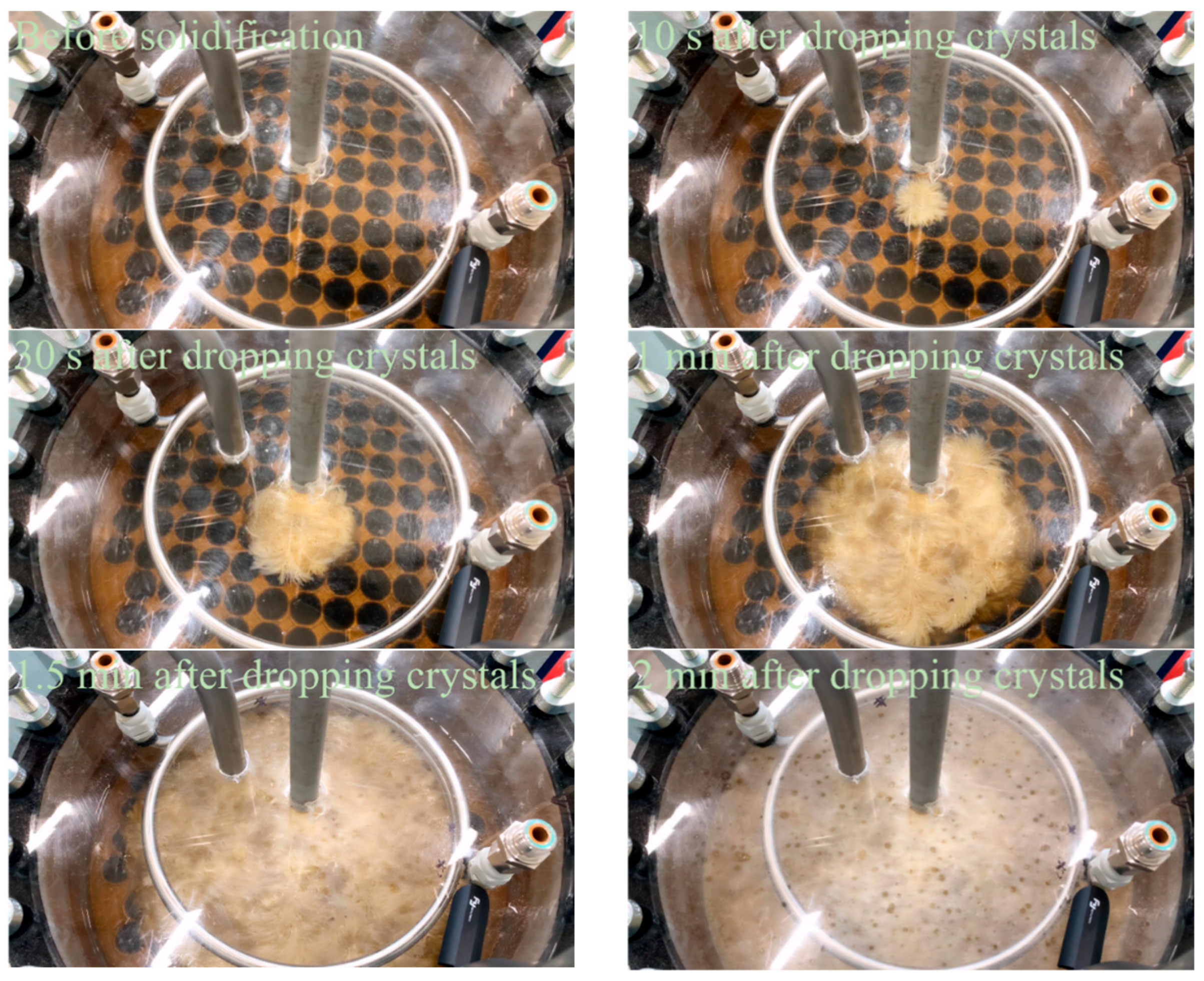
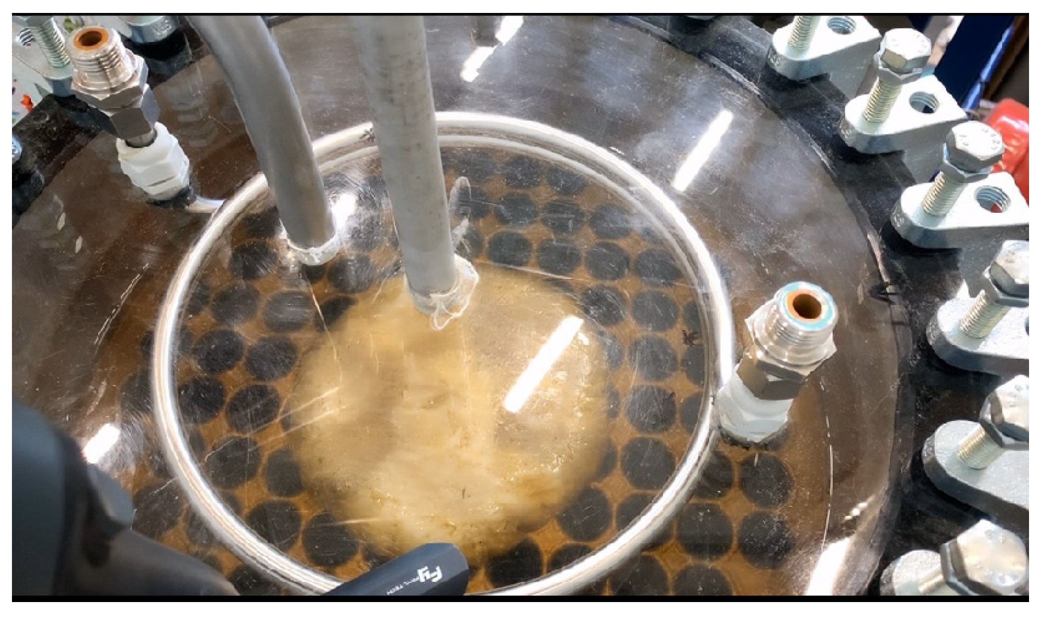
Photos of the heat storage device after solidification was triggered are shown in
Figure 8. Before the start of solidification, the color of the liquid PCM with stable supercooling is light yellow. Solidification is immediately triggered after dropping the SAT crystals. A light yellow crystal is observed immediately in the middle of the liquid surface. Then, filamentous crystals are formed gradually from the middle to the side. The movement of the liquid–solid interface is faster than that of self-solidification. After 2 min, the whole supercooled PCM in view solidifies into a dense solid PCM. Most of the latent heat is released within 2 min. Then, the transparency of the glass window is reduced, and visual observation in the heat storage is difficult.
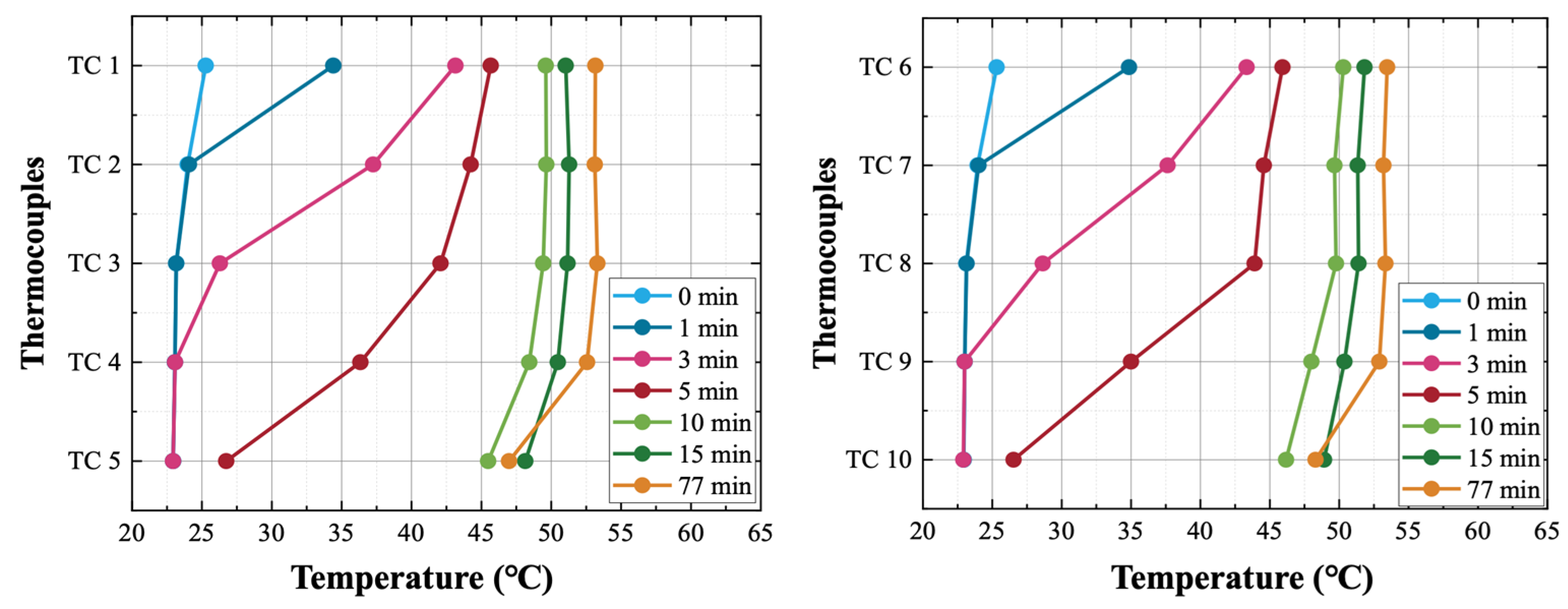
3.2.2. Surface Temperature in Triggered-Solidification
Figure 9 shows the surface temperature of the heat storage after the beginning of triggered-solidification. From the figure, it can be observed that the surface temperature of the whole heat storage device has been cooled down to about 23 °C before solidification is triggered. When solidification of the supercooled PCM is triggered by dropping crystal, the stored latent heat is released from the solidifying PCM to the HTF and then to the thermocouples. The HTF is heated to the phase change temperature of the PCM because there is no flow circulation of the HTF.
From
Figure 9, it can be observed that the inlet side wall and the outlet side wall have almost the same temperature increase after triggered-solidification. The SAT crystal is dropped from the top of the heat storage, and the solidification starts on the top interface of the supercooled PCM. The crystallization of the PCM is from top to bottom and from middle to side. Therefore, the top of the heat storage has a higher temperature, and the inlet and outlet side walls have similar temperatures. In the entire solidification process, the maximum temperature of the heat storage is 53.4 °C, which is basically the same as the phase change temperature of the PCM mixture and slightly lower than the phase change temperature of pure SAT (58 °C).
3.3. Analysis of Different Crystal Morphology
In experiments, PCM crystal morphology is influenced by the solidification modes. The morphology of PCMs solidified by triggered-solidification is different from that by self-solidification. By triggered-solidification, the radius of crystal is smaller than that by self-solidification. Crystals solidified by triggered-solidification are denser than those by self-solidification.
The different morphologies are caused by the different modes of crystallization. Self-solidification is typically Branch Crystallization, and then the formed solid PCM has a branch-like structure (
Figure 10). Triggered-solidification is between Branch Crystallization and Plane Crystallization, and then the formed solid PCM has a plane-like structure with tiny needles (
Figure 11).
The supercooling degree is the reason for the different morphologies. The supercooling degree is the driving force of solidification. When triggered-solidification starts, the heat storage device is cooled down to room temperature because of this, and the supercooling degree is about 30 °C. When self-solidification starts, the supercooling degree is smaller. A large supercooling degree gives a larger solidification driving force, resulting in a faster solidification rate. The diminished supercooling degree ΔT in self-solidification originates from suppressed nucleation kinetics, where the limited thermodynamic driving force ΔG exponentially reduces nucleation rates by 2–3 orders of magnitude via the energy barrier ΔG* ∝ 1/(ΔT)2. Conversely, an elevated ΔT (>25 °C) during triggered-solidification simultaneously reduces the critical nucleus radius r* (r* ∝ 1/ΔT) and accelerates crystal growth velocity, enabling rapid spherulitic crystallization.
The manner by which the crystals grow is also affected by the temperature distribution of the liquid PCM. Temperature distribution is divided into positive gradient distribution and negative gradient distribution. A positive gradient distribution is where the liquid temperature increases with the distance from the solid–liquid interface, while a negative gradient distribution is where the liquid temperature decreases with the distance from the solid–liquid interface. When there is a positive temperature gradient, the liquid–solid interface is generally the plane type. This manner of crystal growth is called Plane Crystallization. When there is a negative temperature gradient, the interface is not planar; instead, it looks like a tree branch. This manner of crystal growth is called Branch Crystallization.
3.4. Crystallization Characteristics
The latent heat release of SAT is synchronized with the solidification of supercooled SAT. The release rate is proportionally related to the SAT crystal formation rate. In order to enhance the release rate of SAT latent heat, it is advisable to conduct an in-depth investigation into the solidification characteristics of SAT. In this section, the crystal growth process, growth rate, and morphology of SAT are investigated.
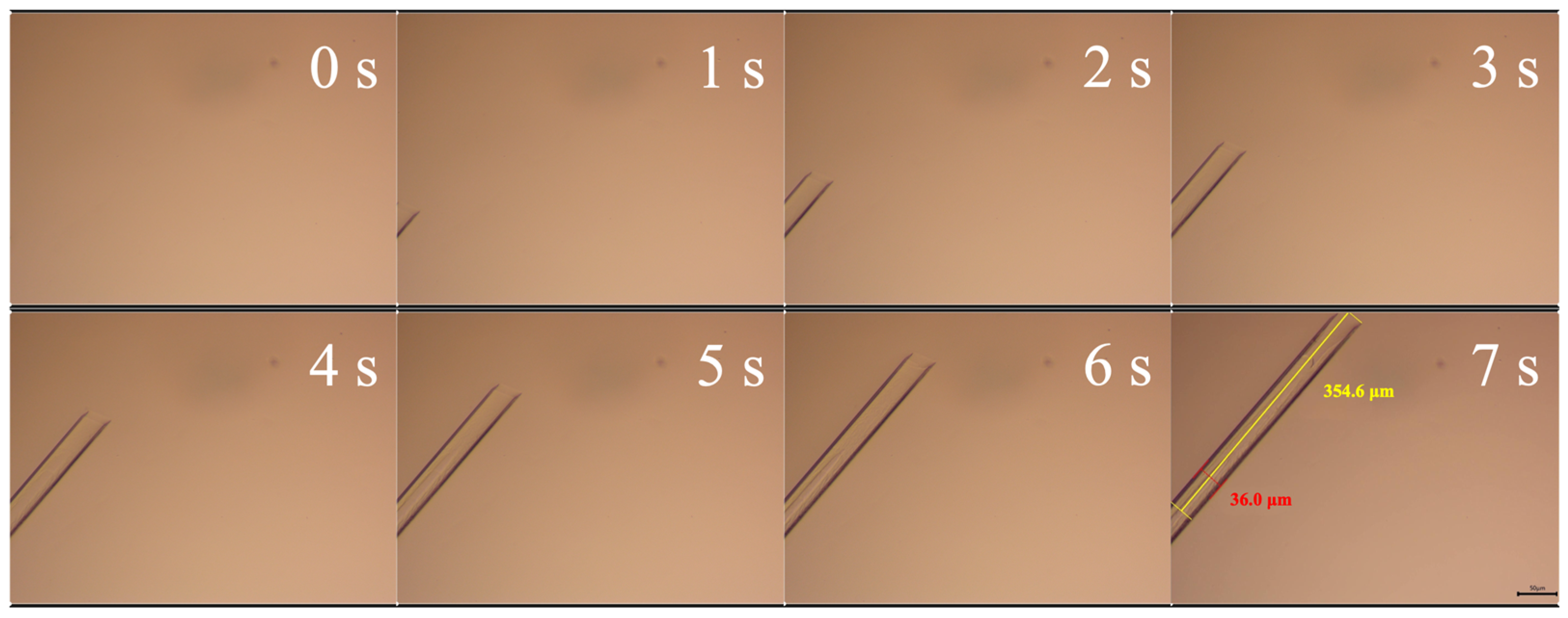
Figure 12 shows the crystallization process of supercooled SAT. Before solidification, the liquid SAT is in a supercooled state. When supercooled SAT solidifies, the needle-shaped crystal is formed, and the SAT crystal grows mainly in an axial direction. The OM images show that the crystal grows about 354.6 μm in 7 s, meaning the growth rate is 59.1 μm/s. The diameter of the formed SAT crystal is about 36.0 μm.
It should be noted that the growth rate of SAT crystals exhibits substantial disparities across diverse experiments. Generally a higher growth rate of SAT crystals can be observed when the supercooling degree of the liquid SAT is higher prior to solidification. In our tests, the maximum axial growth rate is 2564 μm/s, and the maximum radial growth rate is 167 μm/s.
To observe the crystallization clearly, a high speed camera with a high frame rate is recommended over a common industrial camera, and the frame rate should be not less than 1000 fps.
Figure 13 shows the different crystal morphologies of the formed SAT crystals. When the liquid SAT is subjected to stirring, it invariably induces alterations in the morphology of the SAT crystals upon solidification. Before solidification, the liquid SAT is stirred using a magnetic stirrer at a stirring speed of 2500 rpm for 10 min. The formed crystals after solidification with stirring are shown in
Figure 13a. The crystals without stirring are shown in
Figure 13b.
Crystals formed without stirring exhibit strong consistency. The crystals basically grow in the same direction, and there is hardly any situation where the crystals intersect with each other. In contrast, the crystals formed under stirring exhibit multiple growth directions. In the OM image, a distinct pattern of crystal intersections where the crystals crisscross one another can be clearly observed. It can be inferred that the crystals have multiple solidification initiation points and that the growth directions of different crystal clusters diverge from each other. From experimental results, it can be concluded that adding stirring may increase the number of solidification initiation points; however, the latent heat release rate is not enhanced obviously.
Figure 13.
Formed SAT crystals with and without stirring before solidification. (a) With 10 min of stirring. (b) Without stirring.
Figure 13.
Formed SAT crystals with and without stirring before solidification. (a) With 10 min of stirring. (b) Without stirring.
4. Conclusions
This study performs experiments to investigate the heat-releasing performance and the solidification mechanism of a SAT composite. During the experiments, both the temperature changes and the morphological changes of the SAT composite are recorded in totality. Two different solidification modes are observed, and the reasons influencing these solidification modes are analyzed. Further, the crystallization rate of supercooled SAT is determined and analyzed. The following conclusions can be drawn:
During the experiment, based on whether external intervention was needed for the solidification process, the PCM manifested two separate solidification modes—specifically, spontaneous self-solidification and triggered-solidification. The maximum temperature on the outer surface of the device reached 46.2 °C during spontaneous self-solidification and 53.6 °C during triggered-solidification.
Spontaneous self-solidification had a longer solidification time, a slower heat release rate, and an uncontrollable process and formed crystals with an obvious dendritic structure. In contrast, triggered-solidification had a shorter solidification time, a faster heat release rate, and a controllable process and generated crystals with a dense filamentous structure. In the case of spontaneous self-solidification, it took 15 min for the outer surface temperature to reach 45 °C, whereas it only took 5 min in triggered-solidification.
- 2.
The PCM crystal morphology is influenced by the solidification modes.
The morphology of PCMs solidified by triggered-solidification is different from that by self-solidification. By triggered-solidification, the radius of the crystal is smaller than that by self-solidification. The crystal solidified by triggered-solidification is denser than that by self-solidification. Self-solidification is typically Branch Crystallization, and then the formed solid PCM has a branch-like structure. Triggered-solidification is between Branch Crystallization and Plane Crystallization, and the formed solid PCM has a plane-like structure with tiny needles.
- 3.
The axial growth rate is higher than the radial growth rate, and stirring has no influence on the crystal growth rate.
The crystallization process can be recorded in totality using an optical microscope. The growth rate of SAT crystals exhibits substantial disparities across diverse experiments. In this research, the maximum axial growth rate is 2564 μm/s, and the maximum radial growth rate is 167 μm/s. Adding stirring may increase the number of solidification initiation points, but the latent heat release rate is not enhanced obviously. The crystals formed under stirring exhibit multiple growth directions. After 10 min of stirring, a distinct pattern of crystal intersections where the crystals crisscross one another can be clearly observed.
The distinct solidification behaviors of SAT that were observed, particularly the rapid, controllable heat release of triggered-solidification, offer significant advantages for TES applications requiring fast and on-demand energy discharge, enhancing system responsiveness and efficiency. The correlation between solidification mode and crystal structure suggests the potential for optimizing heat transfer efficiency within the PCM and at heat exchanger interfaces. Understanding these modes provides crucial guidance for tailoring SAT-based TES systems to specific operational needs, ultimately improving energy utilization efficiency and thermal management performance.
Author Contributions
Conceptualization, G.W. (Gang Wang); methodology, T.Y.; software, P.L.; formal analysis, S.Z. and C.Q.; investigation, G.W. (Gang Wang); resources, G.W. (Gaosheng Wei); data curation, C.Q.; writing—original draft, D.Z.; writing—review and editing, G.W. (Gang Wang); supervision, G.W. (Gaosheng Wei). All authors have read and agreed to the published version of the manuscript.
Funding
This research was financially supported by the Natural Science Foundation of Xinjiang Uygur Autonomous Region (2022D01B137).
Data Availability Statement
The data that support the findings of this study are available from the corresponding author upon reasonable request.
Conflicts of Interest
Author Tielei Yan was employed by the company State Power Investment Corporation Xinjiang Energy and Chemical Co., Ltd. The remaining authors declare that the research was conducted in the absence of any commercial or financial relationships that could be construed as a potential conflict of interest.
Abbreviations
| SAT | sodium acetate trihydrate |
| PCM | phase change material |
| TES | thermal energy storage |
| HTF | heat transfer fluid |
| SEM | scanning electron microscope |
| OM | optical microscope |
| DSP | disodium hydrogen phosphate |
| EG | expanded graphite |
| PEG | polyethylene glycol |
| LA | lauric acid |
| GO | graphene oxide |
| MGO | modified graphene oxide |
| NPG | neopentyl glycol |
| ZNH | zinc nitrate hexahydrate |
| SDBS | sodium dodecyl benzene sulfonate |
| MPEG | methoxy polyethylene glycol |
| ACs | aromatic acyl chlorides |
| BN | boron nitride |
| PbO | lead oxide |
| PS | polystyrene |
References
- Baghaei Oskouei, S.; Frate, G.F.; Christodoulaki, R.; Bayer, Ö.; Akmandor, İ.S.; Desideri, U.; Ferrari, L.; Drosou, V.; Tarı, İ. Solar-powered hybrid energy storage system with phase change materials. Energy Convers. Manag. 2024, 302, 118117. [Google Scholar] [CrossRef]
- Lalau, Y.; Rigal, S.; Bédécarrats, J.P.; Haillot, D. Latent Thermal Energy Storage System for Heat Recovery between 120 and 150 °C: Material Stability and Corrosion. Energies 2024, 17, 787. [Google Scholar] [CrossRef]
- Gao, M.; Furbo, S.; Kong, W.; Wang, D.; Fan, J. Validation and optimization of a solar district heating system with large scale heat storage. J. Clean. Prod. 2024, 484, 144360. [Google Scholar] [CrossRef]
- Leong, K.Y.; Hasbi, S.; Gurunathan, B.A. State of art review on the solidification and melting characteristics of phase change material in triplex-tube thermal energy storage. J. Energy Storage 2021, 41, 102932. [Google Scholar] [CrossRef]
- Guo, J.; Dong, J.; Zou, B.; Wang, H.; Zhu, L.; Jiang, Y. Experimental investigation on the effects of phase change material and different ventilation modes on the thermal storage, space heating and energy consumption characteristics of ventilated mortar blocks. J. Energy Storage 2021, 41, 102817. [Google Scholar] [CrossRef]
- Poopalam, K.D.; Raghunanan, L.; Bouzidi, L.; Yeong, S.K.; Narine, S.S. Aliphatic fatty diamide as renewable phase change materials for thermal energy storage. J. Energy Storage 2021, 42, 102934. [Google Scholar] [CrossRef]
- Huang, H.; Xiao, Y.; Lin, J.; Zhou, T.; Liu, Y.; Zhao, Q. Improvement of the efficiency of solar thermal energy storage systems by cascading a PCM unit with a water tank. J. Clean. Prod. 2020, 245, 118864. [Google Scholar] [CrossRef]
- Ait, I.; Charai, M.; Es-sakali, N. Evaluating passive PCM performance in building envelopes for semi-arid climate: Experimental and numerical insights on hysteresis, sub-cooling, and energy savings. J. Build. Eng. 2024, 98, 111161. [Google Scholar] [CrossRef]
- Lafta, F.; Fadhil, A.; Togun, H.; Chattopadhyay, A.; Al-obaidi, M.A.; Sharma, B.K. Investigating the impact of fin configuration on phase change material melting in square cells: A numerical study. J. Energy Storage 2025, 105, 114680. [Google Scholar]
- Kiyak, B.; Oztop, H.F.; Biswas, N.; Selimefendigil, F. Effects of geometrical configurations on melting and solidification processes in phase change materials. Appl. Therm. Eng. 2025, 258, 124726. [Google Scholar] [CrossRef]
- Husniatul, K.; Cui, D.; Lu, H.; Xu, X.; Men, Z.; Wang, S. Comprehensive analysis of polyethylene glycol—lauric acid as a promising phase change material: Spectroscopic, thermal, and quantum insights. J. Mol. Liq. 2024, 415, 126261. [Google Scholar] [CrossRef]
- Mostafa, S.; Ghaffari, M.; Mohammad, S.; Hosseini, J. A study on nano-graphene oxide surface modification for the design of paraffin / graphene oxide phase change material. J. Energy Storage 2024, 101, 113738. [Google Scholar] [CrossRef]
- Zhou, G.; Zhu, M.; Xiang, Y. Effect of percussion vibration on solidification of supercooled salt hydrate PCM in thermal storage unit. Renew. Energy 2018, 126, 537–544. [Google Scholar] [CrossRef]
- Zhou, G.; Xiang, Y. Experimental investigations on stable supercooling performance of sodium acetate trihydrate PCM for thermal storage. Sol. Energy 2017, 155, 1261–1272. [Google Scholar] [CrossRef]
- Kong, W.; Dannemand, M.; Johansen, J.B.; Fan, J.; Dragsted, J.; Englmair, G.; Furbo, S. Experimental investigations on heat content of supercooled sodium acetate trihydrate by a simple heat loss method. Sol. Energy 2016, 139, 249–257. [Google Scholar] [CrossRef]
- Wang, G.; Dannemand, M.; Xu, C.; Englmair, G.; Furbo, S.; Fan, J. Thermal characteristics of a long-term heat storage unit with sodium acetate trihydrate. Appl. Therm. Eng. 2021, 187, 116563. [Google Scholar] [CrossRef]
- Englmair, G.; Moser, C.; Furbo, S.; Dannemand, M.; Fan, J. Design and functionality of a segmented heat-storage prototype utilizing stable supercooling of sodium acetate trihydrate in a solar heating system. Appl. Energy 2018, 221, 522–534. [Google Scholar] [CrossRef]
- Hua, W.; Zhang, X.; Han, X.; Wang, X. Preparation and Nucleation Stability Analysis of Modified Sodium Acetate Trihydrate. Acta Energiae Solaris Sin. 2020, 41, 215–222. [Google Scholar] [CrossRef]
- Ortaç, B.; Mutlu, S.; Baskan, T.; Yilmaz, S.S.; Yilmaz, A.H.; Erol, B. Thermal Conductivity and Phase-Change Properties of Boron Nitride—Lead Oxide Nanoparticle-Doped Polymer Nanocomposites. Polymers 2023, 15, 2326. [Google Scholar] [CrossRef] [PubMed]
- Wang, S.; Wang, C.; Hussain, M.B.; Cheng, X.; Wang, Z. Study on Performance Improvement of Sodium Acetate Trihydrate in Thermal Energy Storage System by Disturbance. Processes 2022, 10, 1093. [Google Scholar] [CrossRef]
- Chakraborty, A.; Noh, J.; Shamberger, P.; Yu, C. Unveiling real-time crystallization with nucleators and thickeners for zinc nitrate hexahydrate as a phase change material. Energy Storage 2023, 5, e417. [Google Scholar] [CrossRef]
- Boland, Y.; Fontaine, G.; Bourbigot, S.; Pierlot, C. Effect of emulsification step on calcium carbonate encapsulated eicosane and incorporation into geopolymer. J. Surfactants Deterg. 2024, 28, 333–343. [Google Scholar] [CrossRef]
- Angel-López, A.; Norambuena, Á.; Arriaza-Echanes, C.; Terraza, C.A.; Tundidor-Camba, A.; Coll, D.; Ortiz, P.A. Development of Novel Phase-Change Materials Derived from Methoxy Polyethylene Glycol and Aromatic Acyl Chlorides. Polymers 2023, 15, 3069. [Google Scholar] [CrossRef] [PubMed]
- Serrano, A.; Dauvergne, J.L.; Doppiu, S.; Del Barrio, E.P. Neopentyl glycol as active supporting media in shape-stabilized PCMs. Materials 2019, 12, 3169. [Google Scholar] [CrossRef] [PubMed]
- Sun, W.; Xu, X.; Zhang, T.; Wu, Z.; Xu, Y. Preparation and Thermal Performance Study of a Novel Organic–Inorganic Eutectic Phase Change Material Based on Sodium Acetate Trihydrate and Polyethylene Glycol for Heat Recovery. Materials 2025, 18, 164. [Google Scholar] [CrossRef] [PubMed]
- Yan, T.S.; Li, T.X.; Xu, J.X.; Chao, J.W. Understanding the transition process of phase change and dehydration reaction of salt hydrate for thermal energy storage. Appl. Therm. Eng. 2020, 166, 114655. [Google Scholar] [CrossRef]
| Disclaimer/Publisher’s Note: The statements, opinions and data contained in all publications are solely those of the individual author(s) and contributor(s) and not of MDPI and/or the editor(s). MDPI and/or the editor(s) disclaim responsibility for any injury to people or property resulting from any ideas, methods, instructions or products referred to in the content. |
© 2025 by the authors. Licensee MDPI, Basel, Switzerland. This article is an open access article distributed under the terms and conditions of the Creative Commons Attribution (CC BY) license (https://creativecommons.org/licenses/by/4.0/).


 ,
, 


