2. Review of Recent Research
Scientific studies focusing on the analysis of additional losses in the armature windings of high-speed Ems indicate several physical phenomena that affect these losses. First of all, there is the skin effect, which leads to a non-uniform distribution of current density both across the entire slot cross-section and within the cross-section of an individual conductor in the slot. Usually, the so-called proximity effect is considered at the same time because it results from the mutual interaction of the magnetic fields of nearby conductors. This interaction affects the distribution of current density in the cross-section of these conductors.
The literature on the subject indicates many different interpretations regarding the causes of the proximity effect, but in our opinion, it is a special form of manifestation of the skin effect. In addition, research often considers circulating currents in phase windings. These arise from the unequal positioning of slot sections of individual conductors forming the coil relative to the spatial distribution of the magnetic field in the machine’s air gap. The formation of circulating currents is also possible in the case where groups of phase winding coils are combined into several parallel branches.
The most comprehensive discussion on the causes of additional losses is presented in [
1], where the study focuses not only on the development of possible theoretical approaches to the quantitative analysis of this problem but also on the practical implementation of windings with a reduced level of additional losses.
Among the main methods for investigating additional losses in electrical machine windings, three principal approaches can be distinguished:
Analytical approaches, confirmed by calculations derived on the basis of many numerical methods [
2,
3,
4,
5];
Comprehensive analysis using the finite element method (FEM analysis) with a two- or three-dimensional approach [
6,
7,
8,
9];
Methods applying a probability theory and mathematical statistics [
10,
11,
12].
We note that the vast majority of studies on this subject emphasize the need to take into account additional losses already at the design stage of electrical machines.
The study reported in [
3] contains a comprehensive review of analytical models applicable for calculating losses in high-speed machine windings. According to the authors, the analytical method utilized for calculating losses resulting from the proximity effect is feasible only if the response from the armature is taken into account, whereas the effect of circulating currents cannot be determined without a detailed numerical analysis, for instance, by the application of FEM tools.
In the studies [
13,
14], it was established that an increase in the number of parallel conductors in the coils of high-speed machines does not always lead to a reduction in losses compared to coils comprising one conductor without separation into parallel branches. This becomes particularly important in the case of poorly filled slots, where the correct arrangement of conductors within the slot is crucial [
15]. The authors of [
16], dedicated to determining additional losses in high-power PMSM bar windings with conductor transposition, mention the same phenomenon.
In the studies [
2,
17], the issue related to additional losses is investigated in slotless machines with permanent magnets. The phase winding conductors in such machines are not isolated by the magnetic core from the inductor field. This indicates that minimizing additional losses in this type of design is particularly relevant. In the work [
17], a reduction in rotor losses is also found in machines including this type of winding.
The challenges of the mathematical modeling of physical processes that provides the means to determine additional losses in EM windings during magnetic flux switching are the subject of the research in [
6]. The efficiency of conductor design and temperature is taken into account. In the study described in [
18], the researchers discovered operating modes in which AC winding losses can decrease along with a temperature increase.
In the studies reported in [
3,
8,
9,
11], as well as many others, a range of design factors affecting additional losses in armature windings are discussed. This, in particular, includes the design and dimensions of the slot and the section around the slot, together with the arrangement of individual coil turns within it, the size of the slot opening and the size of the air gap, as well as the transposition of conductors. Furthermore, the effect of the current waveform and its frequency is analyzed in [
7]. In [
19], a method is given for calculating additional losses in the armature winding of a synchronous reluctance motor with permanent magnets. The losses are caused by both the primary harmonic of the current and higher harmonics that result from the switching of the inverter with a pulse width modulation (PWM). The authors were able to successfully perform such calculations on the basis of the post-processing of results for a steady-state operating mode which significantly reduced the time needed for such calculations.
The issue related to the fundamental obstacles faced during the experimental investigations of additional losses in high-speed PMSM machines was described in [
18,
20]. Methods applicable to the identification of losses are being developed that offer the differentiation of losses in copper for direct current, eddy losses in copper and losses in the stator core material. Similar problems also form an important task for asynchronous motors operating with a frequency converter with PWM. The authors of [
7] were faced with the problem of loss separation in such motors and suggested the application of FEM analysis as one of the solutions. In [
21], attention is paid to the method of assessing the efficiency of serial three-phase asynchronous motors, as indicated in international standards. It was found that the existing methods applied for determining additional power losses demonstrate a number of ambiguities.
In [
10,
11], it is stated that in the case of the so-called random-wound windings there is significant variability in the arrangement of conductors in the slots. A failure to take into account this variability leads to a certain level of error in the computational models designed to take into account additional losses. The authors propose a method for predicting such variability based on the statistical analysis of experimental data and a method for calibrating these models which leads to a reduction in the error outlined above. In [
12], a method based on experimental–statistical data analysis is proposed which performs well in determining the probability distribution of the estimation of the losses in the copper winding at the machine design stage.
The authors of [
4] deal with the theoretical solution of the problems of minimizing losses in the superconducting windings of a 10 MW wind turbine. The study highlights the impact of the dimensions and the design of superconductors.
The authors of [
22] investigate losses in the rotor windings of multiphase induction machines resulting from higher-order harmonics of the magnetic field in the air gap. The principal reason for their occurrence is associated with the stator winding topology and the resulting net magnetomotive force. The research confirms that the form of spatial magnetic induction waves plays a crucial role in determining losses in EM windings. However, other sources of spatial higher-order harmonics, such as the presence of stator and rotor teeth or core saturation, are not analyzed quantitatively.
The study in [
23] describes and compares technical and economic indicators in motors with surface-mounted (SPMSM) and interior (IPMSM) permanent magnet configurations. The losses in the stator winding for the SPMSM-type machine are higher than in the IPMSM, which is attributed to the effect of the field effect in the air gap.
The conducted review of the literature reveals that the key factors affecting additional losses in the armature windings of high-speed PMSMs include the design and dimensions of the stator core slot, the size of its opening, the geometry of individual winding conductors, their mutual arrangement within the slots of a single coil, the magnetic properties of the core material and the intensity and distribution of the magnetic field in the working air gap.
The analysis of the relations between the factors given above has either not been carried out at all or their effects have been evaluated indirectly through secondary parameters, specifically the composition of higher-order harmonics in the armature current, the thermal state of the winding and other related indicators.
Taking into account the complexity of the process of additional losses and the non-linear relationships between the above-mentioned factors and these losses, it can be stated that the analytical research methods are based on relatively broad assumptions and do not fully reflect the physical nature of the phenomenon, whereas in terms of performance, their accuracy is close to that of empirical methods.
In high-speed PMSM windings, additional losses typically exceed the fundamental Joule losses. As a result, these losses need to be properly considered during the design phase of such machines.
Scope and Objective of This Study
The classical theory of the phenomenon of the skin effect in the slot parts of electric machine windings does not take into account the possible saturation of the tooth zone with the inductor field or the saturation of the leakage flux paths resulting from the ‘slot’ current. The analytical solution of the field equations was obtained for slots with parallel walls (i.e., one with a rectangular design) assuming a one-dimensional characteristic of the magnetic field. This means that the length of the current density vector in the conductors does not vary along the width of the slot.
The approximate value of the increase in the active winding resistance coefficient
(Field factor), obtained by averaging the values for all conductors within the slot, takes the following form:
where
—number of conductors along the length of the coil;
, —so-called Emde functions;
—reduced height of a single conductor.
The Emde approach can be applied to determine the additional losses in the slot section of the coil, located in a rectangular slot made of magnetic material, according to the following formula:
where
represents the Joule losses in the slot section of the coil.
The calculation in (2) is employed for the purpose of the preliminary assessment of the adopted structural solutions concerned with the selection of conductor dimensions and slot dimensions. However, the analysis of this phenomenon at a higher level of adequacy has revealed a number of factors that can affect the level of additional losses. The most prominent one among these losses is related to the saturation of the tooth region which clearly depends on the excitation flux. The higher the saturation level, the greater the ratio of the magnetic flux that penetrates the slot, altering the course of the skin effect process both quantitatively and qualitatively. It was remarked that the expression in (2) for the case of the saturation of the tooth zone in the range of 1.6 ÷ 1.8 T could lead to a considerable level of error (>30%) in the determination of the value of
[
9].
It is commonly recognized that the design of the phase coils of an armature winding with multiple parallel conductors can lead to parasitic circulating currents, in which the losses can make up a significant part of the total losses faced in high-speed PMSMs. It is understandable that the existing analytical methods cannot take into account the true effect of saturation and the presence of circulating currents in principle.
The aim of this study is to conduct a quantitative analysis of the effect of magnetic circuit saturation with the excitation field, the armature response field, the mutual arrangement of winding conductors and their dimensions on additional energy losses in the coils of phase windings of electric machines, whose turns consist of a number of separate, insulated conductors, coupled to each other only at both ends of each coil or phase.
In the following, we will use the term elementary conductors to refer to such conductors, and a conductor consisting of separate elementary conductors will be referred to as an effective conductor.
The subject of this study involves the electromagnetic energy conversion processes in multi-turn phase winding coils of high-speed electric machines identified as PMSMs, composed of separately insulated elementary conductors.
With the purpose of achieving the specified goal, the additional losses in the coils were calculated based on the numerical solution of the electrodynamic equations in quasi-steady-state approximation using the FEM. The calculations took into account the actual design of the slot and the conductor, the different arrangements of individual conductors in the slot in relation to each other, the saturation of the magnetic circuit and the occurrence of an excitation field—as the main factors that affect the skin effect process in the slots of electric machines.
3. Mathematical Model Applied in Loss Computations
In order to quantitatively evaluate the parameters of the energy conversion processes in PMSM-type phase windings, a mathematical model was developed for the purpose of calculating the basic and additional losses in a multi-turn coil, the slot parts of which are inserted into a layered ferromagnetic core in two slots with any design. The coil consists of an arbitrary number of elementary conductors with any cross-sectional shape. The model takes into account any layout of individual coil turns in the slot and an arbitrary arrangement of elementary conductors forming these turns. The problem is formulated as two-dimensional and takes into account both the current skin effect and the proximity effect of the conductors. It is assumed that the coil is placed in a variable harmonic magnetic field of the field winding with a specific intensity and in its own stray field, generated by the current flowing through the conductors in this coil.
3.1. Mathematical Notation
The formulation of this problem is based on the Poisson equation in the Coulomb calibration for the magnetic vector potential (
). In invariant notation, it takes the following form:
where
—differential Hamilton operator;
—matrix of the specific electrical conductivity of the environment;
—magnetic vector potential;
—velocity vector of the environment;
—scalar electric potential of the external field.
The current density vector field in this case is uniquely defined by the following formula:
which indicates that the resultant current density vector field comprises the impact of the external electric field, the time-varying magnetic field and the motion of the conductor with a velocity of
in the magnetic field
.
The equation in (3), together with the appropriate boundary conditions, forms the basis for the mathematical statement of the problem of the boundary value applied for calculating the non-stationary magnetic field, taking into account all possible loads of electromagnetic and mechanical origin. The solution to this problem requires integration with respect to both spatial and time coordinates.
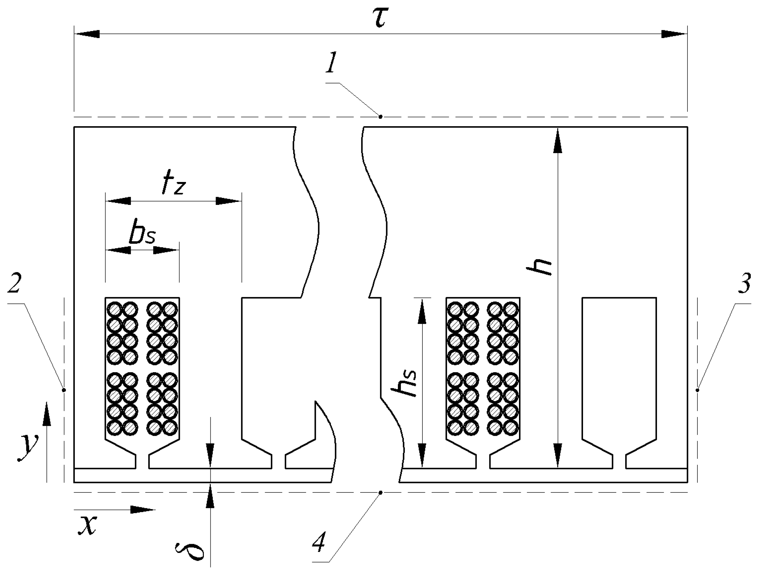
The computational area of the model constitutes a linear extension of a single pole pitch of the armature core with an air gap and is shown in
Figure 1. This figure also contains the lines (surfaces) on which the boundary conditions are imposed. The line on the outer surface of the core, marked as No. 1, is subject to the Neumann condition:
The vertical lines, which represent the axes of symmetry of the two extreme teeth and are marked in the figure as lines denoted as 2 and 3, are subject to the Dirichlet conditions:
for the line marked as 3
where
—pole pitch;
—phase shift between the current of the effective conductor and the radial component of the magnetic induction vector in the air gap of the machine.
The inductor field is given by the linear distribution of the z-projection of the magnetic vector potential along the lower horizontal line marked as line 4 (
Figure 1).
The expressions in (5)–(8) offer the configuration of the external magnetic field in a manner that corresponds to the commonly known ideas about the most probable magnetic flux paths in the tooth zone and in the armature core yoke.
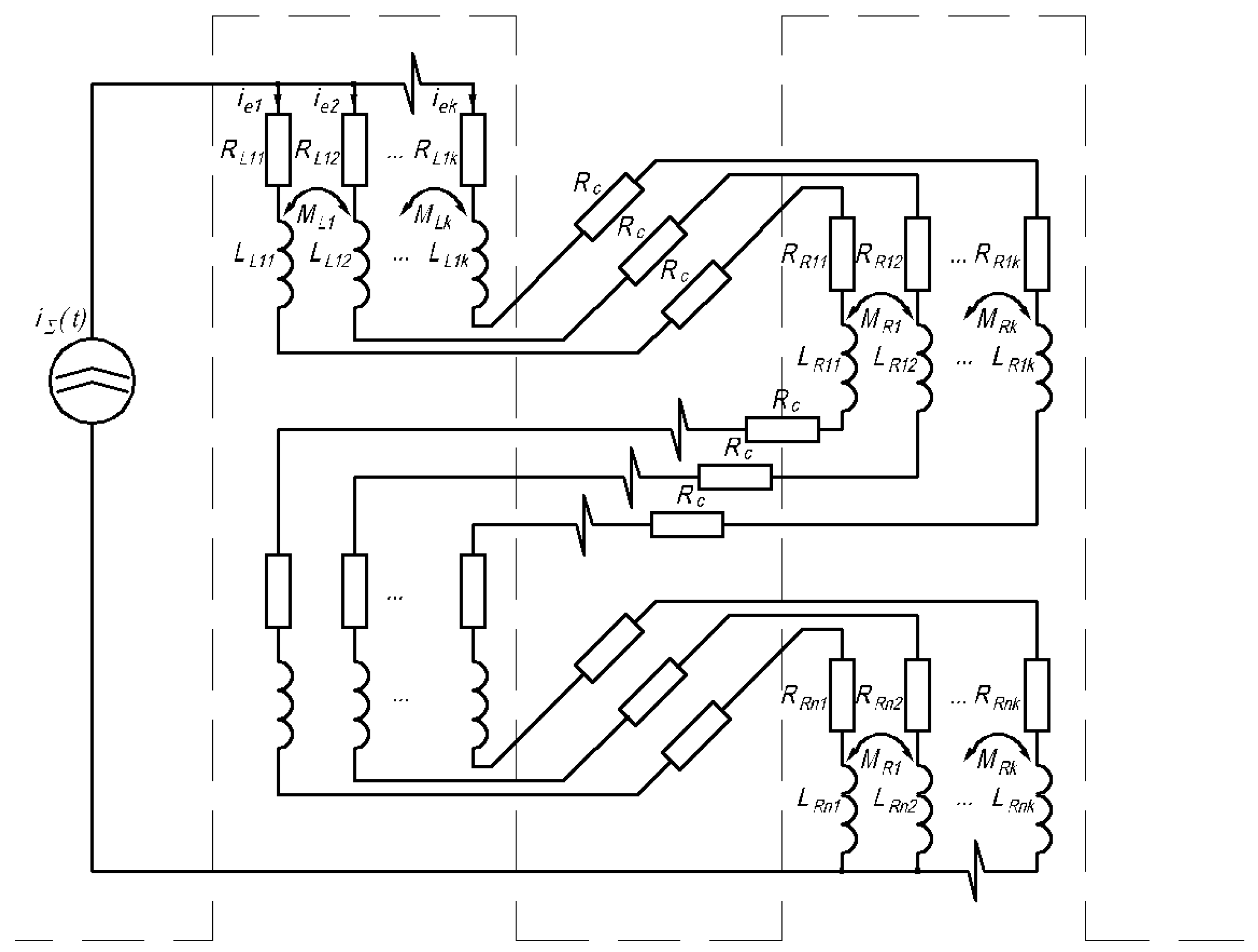
The force acting as an induction in this expression is the current of the effective conductor. The manner in which elementary conductors are connected with each other is defined by the expression obtained from Kirchhoff’s first law for the node of the diagram in
Figure 2.
where
represents the elementary conductor current defined as
, and
is the total number of elementary conductors in a single effective one.
The current of each elementary conductor was determined based on calculations of the current density vector field:
where
—the value of the density vector modulus in an n-th node of the finite element (FE) defined as ;
—current FE node number;
—current FE node number corresponding to number ;
—surface area of FE with a number of .
The power losses in the slot part caused by the thermal activity of the eddy currents were defined as the algebraic total of losses in individual FEs belonging to elementary conductors:
where
—modulus of the node value of the current density vector;
—volume of -th FE with a surface area equal to and a length of .
The expression (3), along with the formulae in (9)–(11) and boundary conditions (5)–(8), constitutes the mathematical statement of the problem of calculating currents in elementary conductors with arbitrary cross-sectional shapes, enclosed in ferromagnetic slots of any shape and located in an external variable magnetic field with a specific strength.
The algorithm of this model was implemented in the ANSYS 16.2 Multiphysics package using the APDL programming language.
3.2. Model Functionality
As we already mentioned earlier, the mathematical model developed in this study takes into account the saturation of the magnetic core by both the inductor flux and the leakage fluxes. The model makes it possible to study how the design of the slots and the geometry of the cross-section of the conductors affect the power losses resulting from both the skin effects and the proximity effect. The model also involves an analysis of the system response to the reduction in the winding pitch. In addition, it is possible to analyze the effect of the mutual arrangement of effective and elementary conductors forming a single coil.
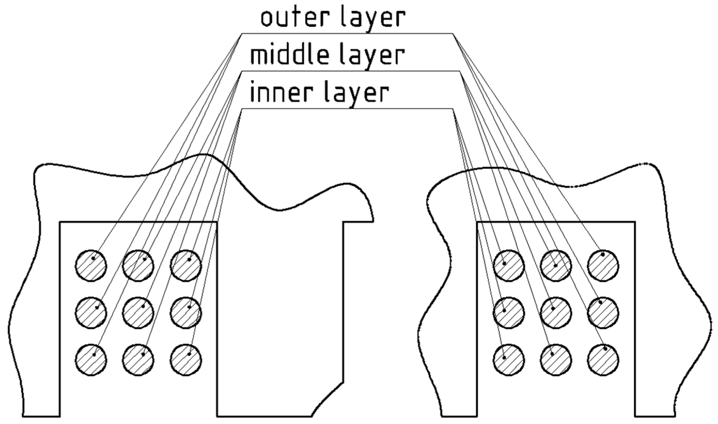
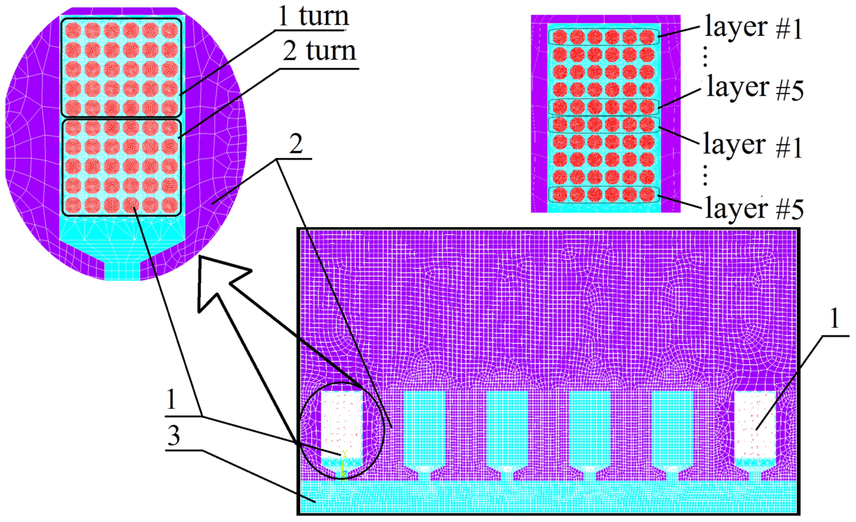
The slotted parts of the coil conductors that are spaced the smallest distance apart from each other are conventionally called conductors of the inner layers of the coil. The conductors that are located the farthest away from the slots are called conductors of the outer layers. The remaining conductors are the conductors of the middle layers (
Figure 3).
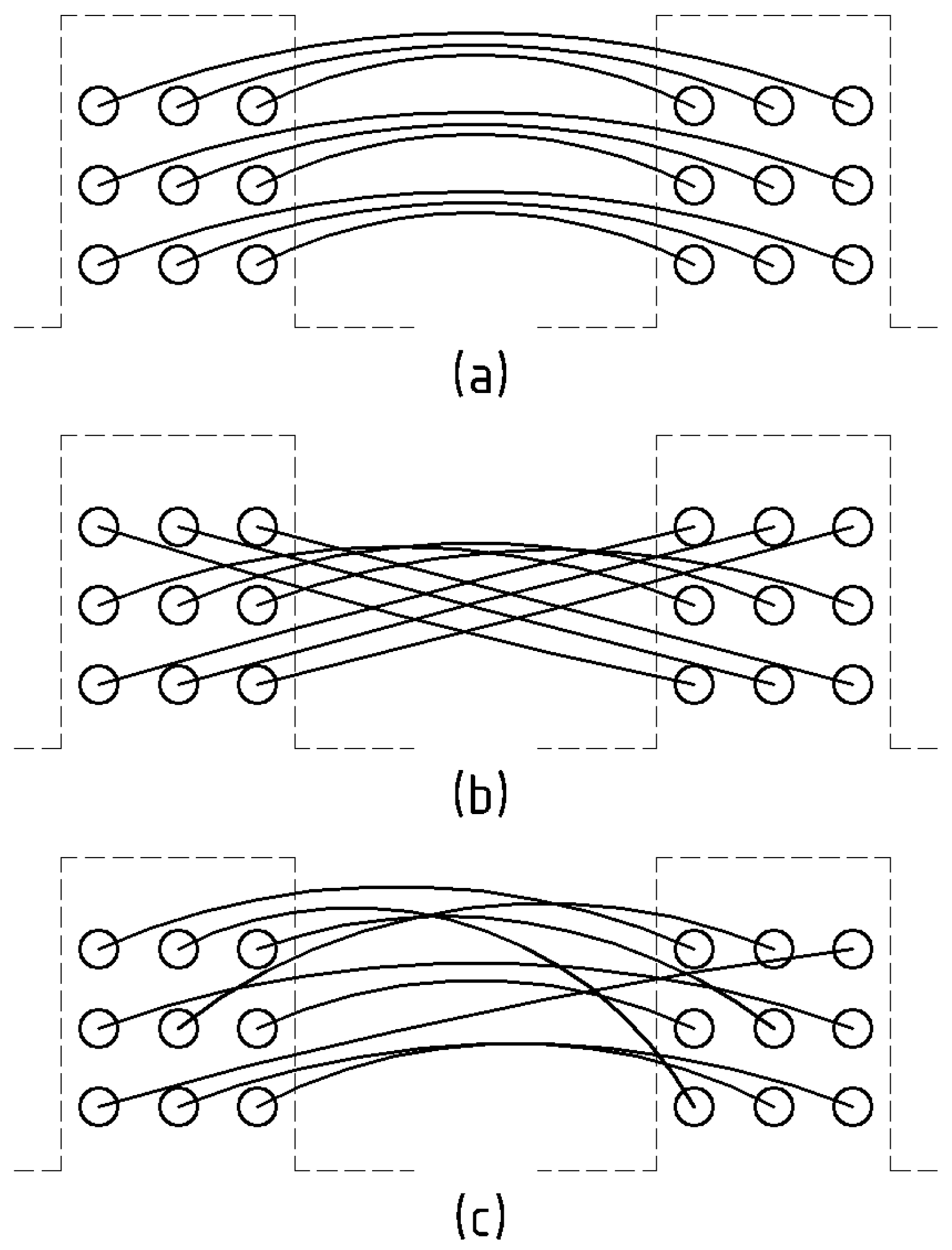
The proposed model accounts for three ways of arranging the coil conductors in relation to each other.
The first method is characterized by the coupling between the conductors of the inner layers in one of the slots and the corresponding conductors of the inner layers in the other slot. The conductors of the middle and outer layers are connected analogously (
Figure 4a). This method replicates the layered manual or automated placement of the armature winding directly within the core slots.
The second method involves connecting the conductors of the inner layers in one slot with the conductors of the outer layers in another slot, while the conductors of the outer layers in that slot are connected to the conductors of the inner layers in the opposite slot (
Figure 4b). The conductors of the middle layers are connected to each other in the same manner as in the case of (a) in
Figure 4. Such an arrangement represents the transposition of the conductors by 180°, generated in the frontal sections of the coil.
The third method describes the connection of the slot parts of the coil conductors in a random manner (
Figure 4c). This method to some extent represents the coil arrangement, previously generated on a template.
In the following, these methods of conductor arrangement will be referred to as layered, transposed and random, respectively.
4. Verification of the Model
For the purpose of verifying the proposed model, a comparison of the calculation results of the power loss distribution in seven elementary conductors connected in a parallel manner and placed in a rectangular open slot was carried out with the results obtained by the analytical method based on the circuit theory, as described in [
24].
To ensure the feasibility of the comparison, the problem was formulated as linear, whereas the radial field was neglected ().
The excitation in this task is executed by a sine-shaped current of the effective conductor with an RMS value equal to and a frequency . The specific resistivity of the conductor material corresponds to copper heated to 100 °C.
Figure 5a shows the division of the computational domain into finite elements, representing a linear development of the cross-section of one stator pole pitch of the electrical machine. The slot dimensions and winding data correspond to the input data provided in
Table 1. The level of discretization of the computational domain is as follows: the number of finite elements is 27,792, and the number of nodes is 83,850.
Calculations were performed for six periods of the supply current, with a time step equal to 1/80 of the period. The results of the magnetic flux density and current density calculations are presented in
Figure 5b,c as raster maps. It should be noted that the areas marked with the same color correspond to a specific range of values of the given physical quantity. The illustrated results correspond to the moment in time t = 0.08 s.
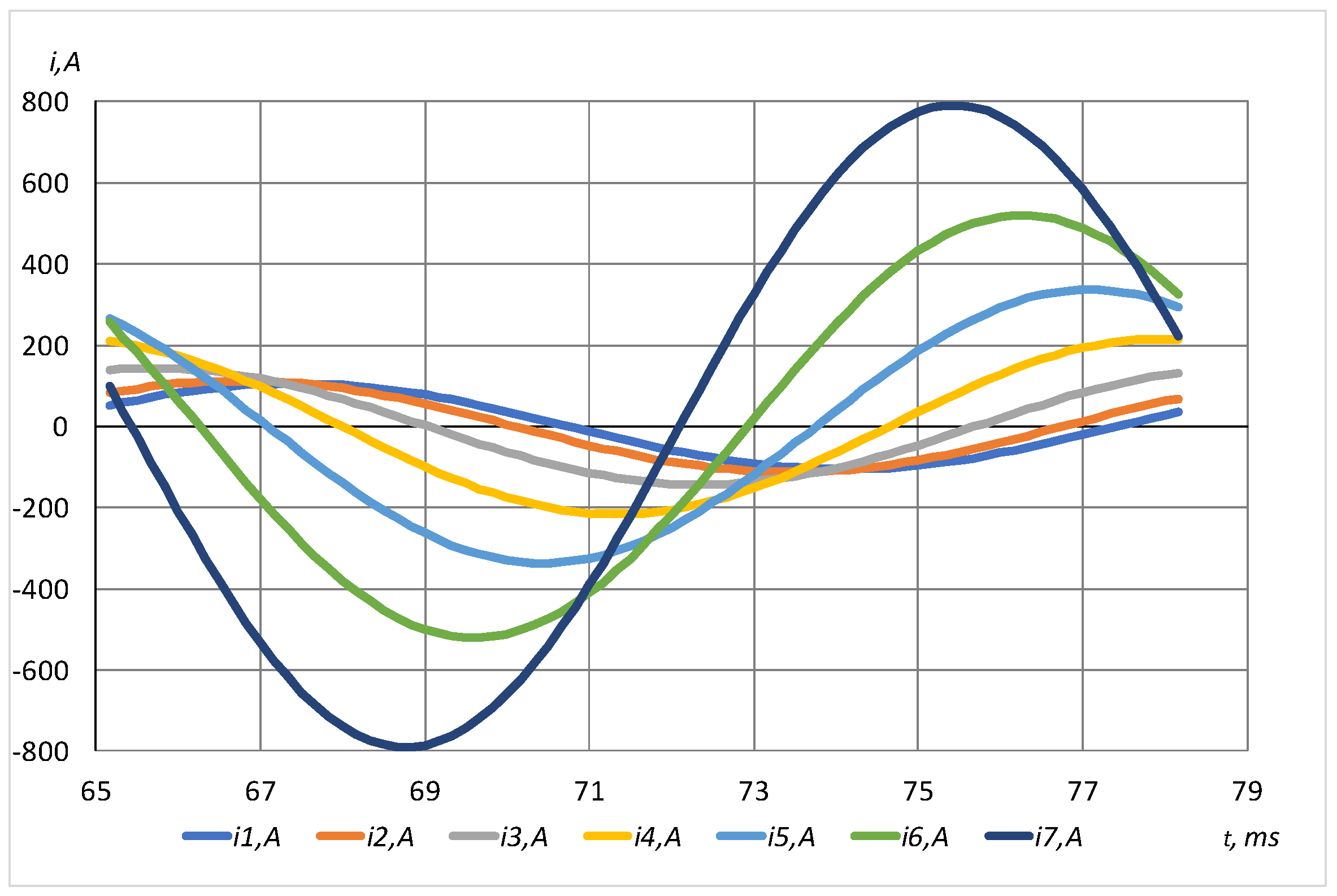
Figure 6 presents the dependencies of the currents of individual elementary conductors on time at the end of the time range—steady-state values.
The processing of the results of the calculations of the current density vector field and losses in elementary conductors consisted in determining the effective values of these quantities.
where
—subsequent step of integration (—step number corresponding to the initiation of the computational period);
, —instantaneous values of the elementary current of the conductor (12) and losses in the elementary conductor (13), respectively;
, —time period and time integration step value, respectively.
For the adequate comparison of the obtained results with the results presented in [
24], the power losses were determined in an analogous manner:
where
—electrical resistance of an elementary conductor for direct current (
).
The results of data processing performed in the mathematical experiment are presented in
Table 2. Let us note that the total DC electrical losses in this problem are 56.125 W per slot and the Field factor
.
The comparative analysis of the results (
Table 2) demonstrates the sufficient accuracy of the proposed model and gives grounds to foresee its adequacy in calculating losses in the multi-turn coils of high-speed machines, taking into account all the factors mentioned previously.
5. Mathematical Experiments
A series of mathematical experiments were conducted to quantitatively evaluate the dependence between additional losses in the armature winding and the degree of saturation of the magnetic core by the excitation field, the saturation of tooth tips by the armature reaction field and the layered, transposed and random mutual arrangement of elementary conductors in the slot.
The model takes into account the slot dimensions and electromagnetic loads (field in the gap and effective conductor current) corresponding to the calculation data of a high-speed PMSM machine with a maximum output of 200 kW and rotational speed of 50.000 rpm.
The input data for modeling, together with the designations adopted in
Figure 1, are presented in
Table 3.
The specific resistance of the conductor material was assumed to be equal to the specific resistance of copper at 20 °C. The magnetization characteristics of the magnetic core correspond to the properties of electrical steel M270-35A (EN 10106:2007).
The computational area is shown in
Figure 7. The calculations were performed for three periods of the supply current. During this time, the currents in the elementary conductors assumed steady states. The time step was 1/80 of the period. The FE model mesh contained 126.530 nodes. The total number of FEs was 49.318.
The first mathematical experiment that was carried out involved a quantitative assessment of the influence of the arrangement of elementary coil conductors in slots on additional losses in these conductors. The experimental conditions take into account the saturation of the magnetic core. The induction forces in this process were as follows:
Effective value of the effective conductor IΣ = 175.4 A;
Current frequency fn = 833.3 Hz;
Amplitude of the radial coordinate of the main field induction;
Phase displacement between current and radial coordinate of induction υ = π/2 rad;
Proportionality coefficient between angular and metric coordinates β = 33.56 rad/m.
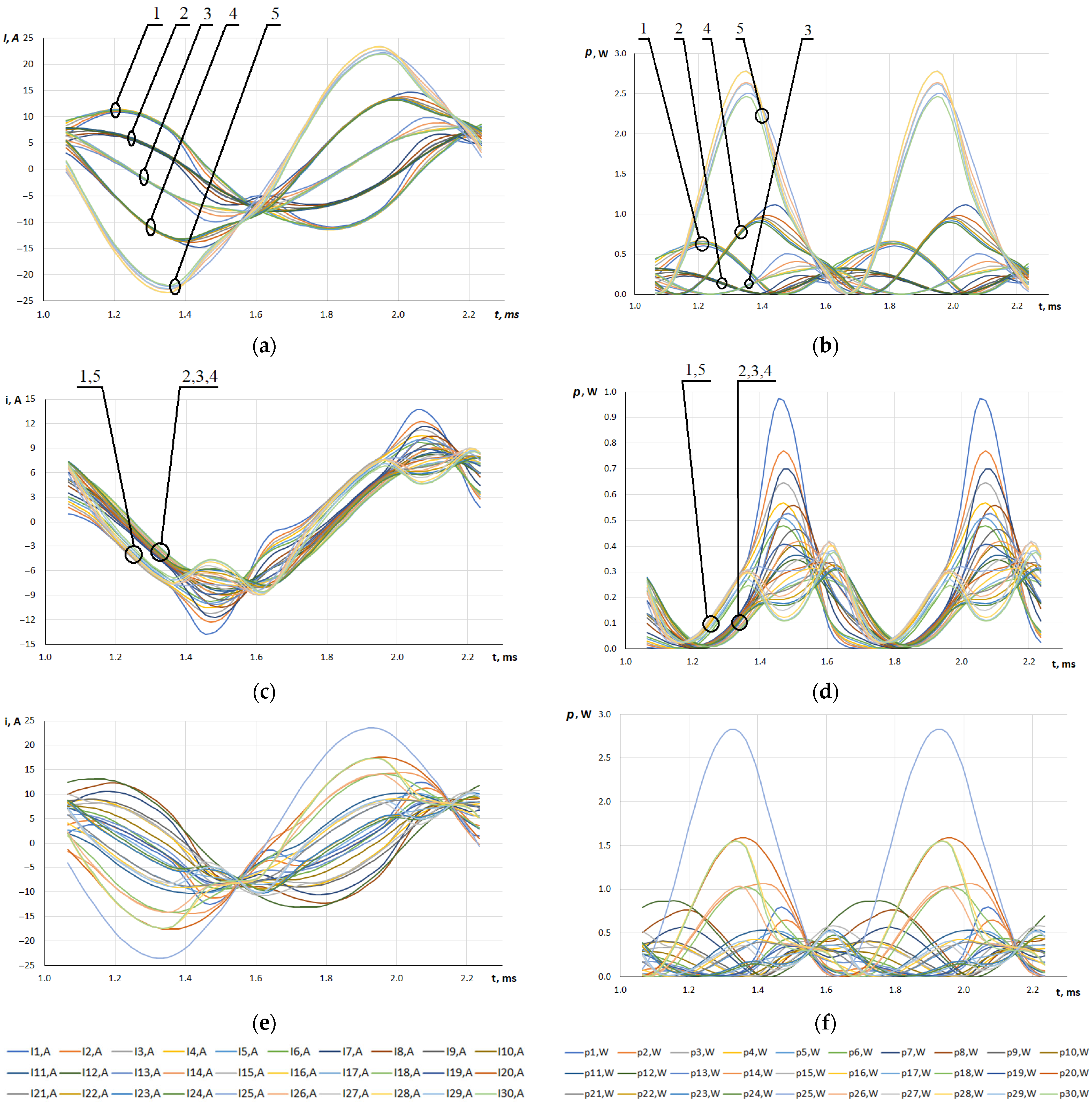
Figure 8 shows the time dependencies of the instantaneous values of the elementary currents of conductors and losses in them for a two-turn coil with a diametric step. The numbers given in the legends in
Figure 8 next to the designations ‘I’ for currents and ‘
p’ for losses correspond to the position of the elementary conductors in the effective conductor, starting from the leftmost conductor in horizontal layer # 1 and terminating with the rightmost conductor in the horizontal layer # 5 (see
Figure 7).
The numbers shown directly on the graphs indicate the assignment of a given group of time dependencies to the horizontal layer of conductors with the appropriate number (see
Figure 7). The time range of the dependencies presented in
Figure 8 corresponds to the last period of the non-stationary process.
On the basis of the analysis of the resulting dependencies, we can state that in the case of a layered arrangement of conductors, the currents and losses in them—analogous in terms of value and phase—are classified according to the number of the horizontal layer they are located in. It can also be seen that the currents of the conductors in layers 1 and 5 act as if they are virtually in an antiphase, which clearly contributes to the increase in the measured level of losses.
The transposed layout eliminates the irregularity of the current distribution in the elementary conductors, which has a positive effect on the value of additional losses in them.
The characteristics of the irregular distribution of currents and losses in the case of the random arrangement of the conductors in slots are similar to that in the case of the layered arrangement, but the number of elementary conductors in which the currents are almost in opposite phase is smaller.
The occurrence of higher harmonics in all relationships—regardless of the arrangement of conductors—results from the saturation of the magnetic core.
All three investigated cases demonstrate that only for a small portion of the half-cycle (≈50–60°), the current density distribution in the transverse direction of the slot (along the x-axis, see
Figure 1) remains virtually unvaried and could be considered as one-dimensional, as it is assumed in the classical theory applied for the description of the phenomenon of the skin effect. Throughout most of the period, differences were noted between the instantaneous values of currents in conductors belonging to the same horizontal layer (
Figure 8). This implies that solutions in the field of designing high-speed electrical machines require taking into account at least the two-dimensional nature of the magnetic field.
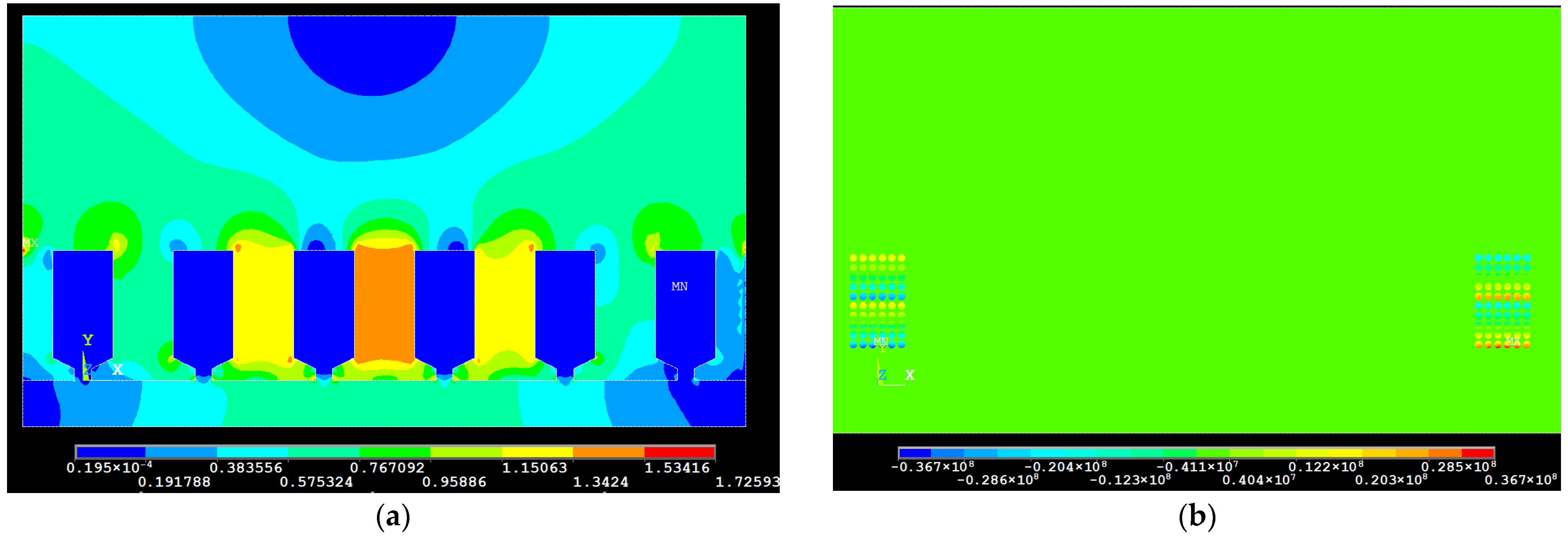
Figure 9 shows a two-dimensional spatial distribution of the magnetic field induction vector modulus across the entire computational region, as well as the current density in the elementary conductors of a two-turn coil with a diameter pitch. The figure pertains to the layered arrangement of conductors and a specific moment in time equal to t = 2.46 ms.
Figure 9a shows the presence of the external field of the inductor (8), which we have identified as an advantage of the proposed approach.
Figure 9b demonstrates that the current density distribution in the conductors located in the left part of the coil slot differs from the corresponding distribution in the right part only in sign. This can serve as a qualitative confirmation of the correctness of the relationship between the currents in the individual elementary conductors, as defined in Equation (9).
Enlarged images of the spatial arrangement of the current density vector modulus in the cross-section of one of the slots are shown in
Figure 10. They make it possible to analyze the current density distribution in individual conductors depending on their arrangement (layered, transposed, or random), as well as over time (during a single half-cycle). It can be seen from
Figure 10d–f that with the transposed layout of conductors, for different moments of time, the current (10) in the corresponding elementary conductors belonging to different turns is the same, while the current density distribution in them is different.
This circumstance indirectly—at the physical level—justifies the reason for the significant reduction in additional losses when the 180° transposition of conductors is applied and—in our opinion—confirms the adequacy of the developed model. The quantitative evaluation of the results of this mathematical experiment is presented in
Table 4. The power losses given therein were calculated only for two slot parts of the coil, each with a length of 240 mm.
The study of the effect of the saturation of the magnetic core with the inductor field showed that at zero Bδ and in a design with a layered arrangement of conductors, the Field factor increased to 3.7, compared to the value of 3.3 in the former case (see
Table 4). This can be attributed to the reduction in the magnetic resistance of the slot leakage flux paths—in particular in the tooth tips—and, consequently, an increase in the level of irregularity of the current distribution in the elementary conductors. Therefore, the saturation of the tooth region with an external field reduces additional power losses in the winding. However, it should be remembered that such saturation simultaneously increases the basic losses in the iron of the magnetic core.
The saturation of the tooth tips only with the field from the coil current was analyzed by changing the value of this current in the range of 0.2 I
Σ to 1.4 I
Σ. The conductor arrangement in the slot remained layered. The effectiveness of the solution was evaluated in relative units, in relation to the square of the effective conductor current. The numerical results are presented in
Table 5.
The resulting data based on calculations (
Table 5) demonstrate a practically proportional relationship between the value of losses in the coil and the square of the current in it. Hence, it can be concluded that at armature currents not exceeding 1.5 times the rated value, the saturation of the leakage flux paths has little effect on the additional losses in the armature winding of the investigated high-speed electric machines.
The impact of the cross-sectional area of elementary conductors on additional losses in the coil was investigated under the assumption of the invariance of the design and dimensions of the slots in which the coil is enclosed. In the mathematical model, the cross-section of the elementary conductors is designed as a regular octagon. The variable quantity forms the diameter of the circle inscribed in such an octagon. It is not related to any series of standardized diameters of winding wires. The values of the diameter of this circle were selected so that with an appropriate change in the number of elementary conductors the total cross-section of the effective conductor remains constant.
In the following, the diameter of this inscribed circle will be referred to as the diameter of the elementary conductor.
Five different coil winding designs were examined, as follows:
Five horizontal layers each comprising six conductors (5 × 6) with Ø 1.0 mm (
Figure 7);
4 × 5 conductors, Ø 1.225 mm;
3 × 4 conductors, Ø 1.581 mm;
3 × 3 conductors, Ø 1.826 mm;
2 × 2 conductors, Ø 2.739 mm.
The total cross-section of the effective conductor in all these cases was 24.9 mm2, and a layered arrangement of conductors was adopted.
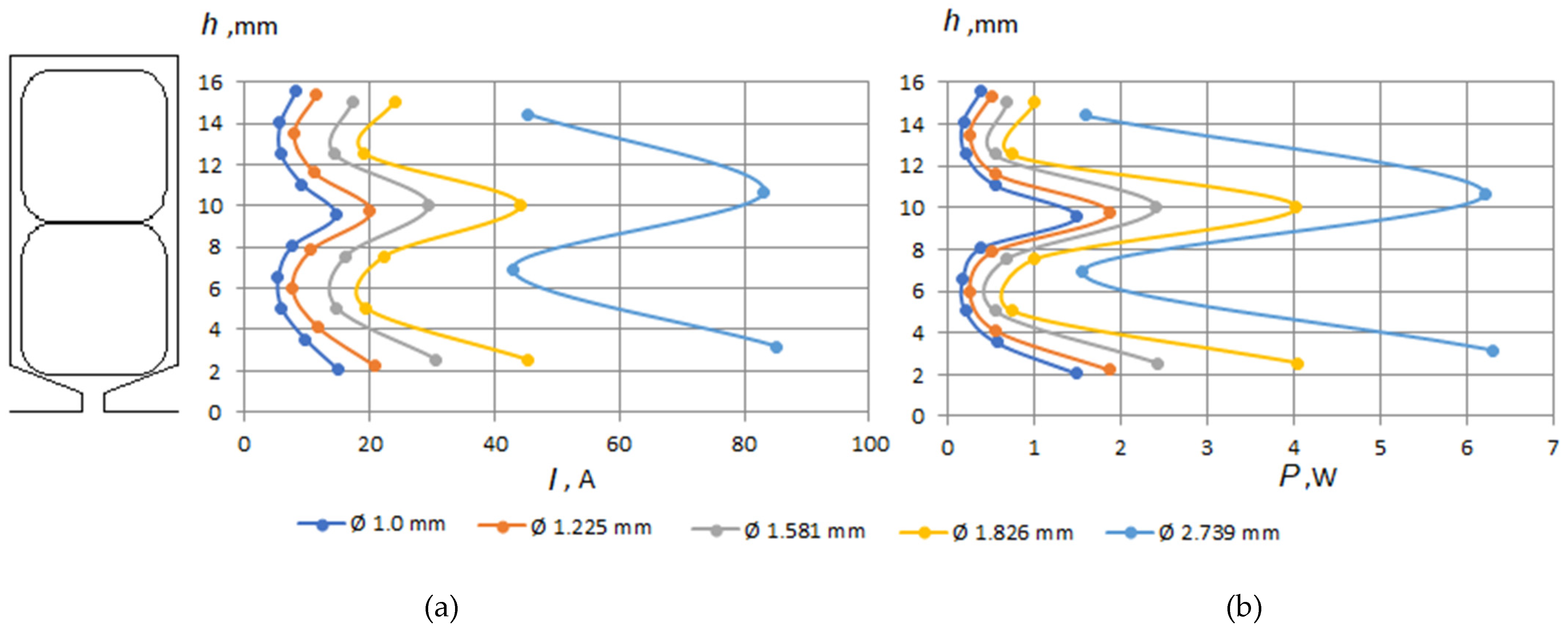
Figure 11 presents selected results of this study, namely, the distribution of effective current values in the elementary conductors arranged along the y coordinate (see
Figure 1) in the inner layer of the coil (see
Figure 3) and the distribution of effective loss values along the slot height, averaged for all conductors in the horizontal layers of the coil.
In the conditions discussed in this study, according to the classical theory of the skin effect phenomenon, an increase in the dimension of the conductors in the y direction leads to an increase in the current values or current densities in the conductors located in the lower layers of both turns (layers # 5,
Figure 7). This is attributable to a local change in the inductive impedance of the elementary electric circuits created by these conductors. The losses with respect to the slot height are also characterized by a similar distribution. However, the total losses in the tested two-turn coil placed in a semi-closed slot are much less dependent on the change in the diameter of the elementary conductor and, consequently, on the number of elementary conductors in the effective one. For example, for the design alternative featuring 5 × 6 conductors of Ø 1.0 mm, the losses amounted to 69.7 W, for 4 × 5 conductors of Ø 1.225 mm, the losses were 66.1 W, for 3 × 4 conductors of Ø 1.581 mm, the losses were 61.9 W, for 3 × 3 conductors of Ø 1.826 mm, the losses were 74.2 W, and for 2 × 2 conductors of Ø 2.739 mm, the losses were 74.4 W. This is due to both the change in the total number of conductors in the slot and the relatively weak magnetic field inside it (≈0.1 T).
The depth of field penetration into copper:
where
represents the absolute magnetic permeability of the vacuum for a current frequency fn = 833 Hz, at which the mathematical experiment was conducted, which is equal to ≈2.3 mm and comparable with the diameter of the elementary conductors.
Despite the relatively small effect of changing the conductor diameters on the total additional losses in the coil, the irregular distribution of losses in the slot leads to the local overheating of individual layers in the coil. Insufficiently effective cooling can lead to faults in the coil insulation.
6. Experimental Study
In order to confirm the results and conclusions derived from the simulation studies, a number of physical experiments were conducted. These experiments were performed using a setup dedicated to this purpose and consisting of a magnetic core, tested multi-turn coils placed in its slots, power sources and measuring equipment (oscilloscope).
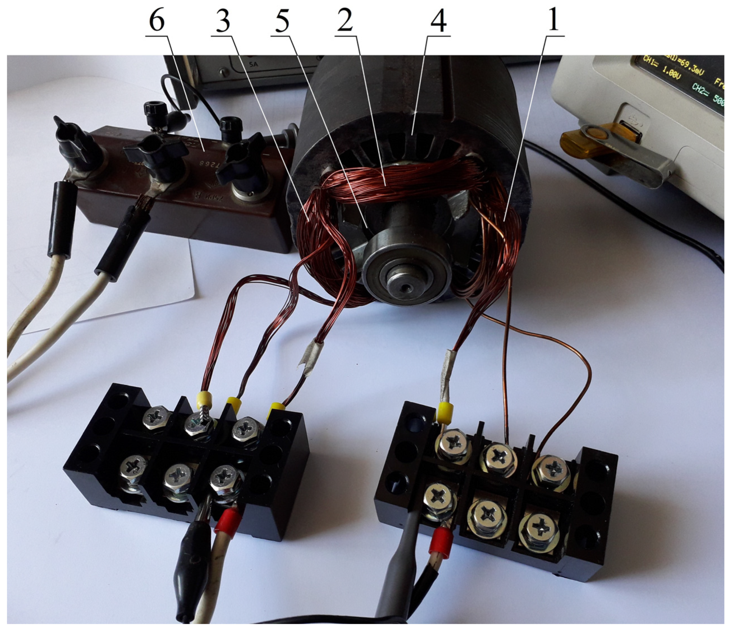
The magnetic core (No. 4 in
Figure 12) is cylindrical in shape and contains 24 semi-closed trapezoidal slots arranged around its internal hole of Ø 61 mm. Three coils made of insulated copper wires with a circular cross-section are inserted into the slots.
The first coil (No. 1) is wound with a wire Ø 1.4/1.46 mm (wire diameters without/with insulation) and comprises 14 turns. The cross-section of the wire is 1.54 mm
2. The second (No. 2) and third (No. 3) coils are made of a conductor consisting of 13 elementary conductors, Ø 0.4/0.45 mm each. The total cross-section of the effective conductor is 1.63 mm
2. These coils also have 14 turns in a series. The conductors of coil No. 2 are arranged in layers in the slots, as shown in
Figure 4a, whereas in coil No. 3, transposition is applied (
Figure 4b).
A ferromagnetic rotor core from an asynchronous motor with a short-circuit winding (No. 5 in
Figure 12) with an external diameter of Ø 60.8 mm was applied in the core interior to increase the magnetic conductivity of the flux paths generated by the current in the coil.
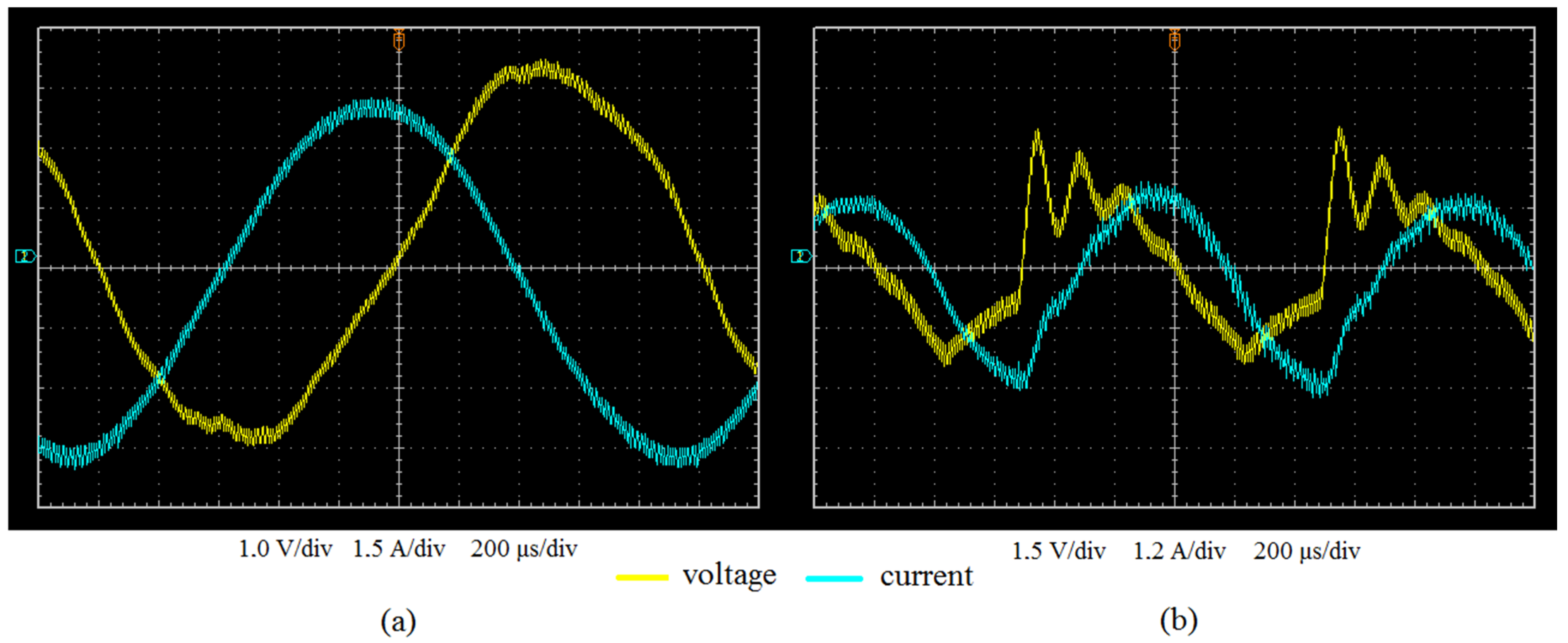
Each coil was sequentially powered with a sine-shaped voltage at a frequency of approximately ≈500 Hz and a multi-harmonic voltage with a fundamental harmonic at a frequency of approximately ≈1000 Hz.
Following the registration of the instantaneous values of the appropriate voltages and currents (
Figure 13), data processing was initiated in order to determine the power losses. The active power losses in all analyzed cases were determined as the average value of the product of the voltage and current during one period of time, T:
The results of the experimental data processing are summarized in
Table 6.
The quantitative analysis of power losses and the Field factor conducted on the basis of
Table 6 here was carried out without identifying the losses due to the magnetization reversal of the magnetic circuit core. Due to the low saturation level, these core losses are considered to be relatively small.
The results gained from the study confirm the fact that losses in coils are reduced when the effective conductor is separated into elementary ones and when the transposition of conductors is utilized. However, the obtained experimental value of these losses is relatively smaller than the one derived from calculations. Such a difference can be attributed to the discrepancy between the actual arrangement of conductors in the slot (
Figure 12) and the idealization of their arrangement (
Figure 4b).
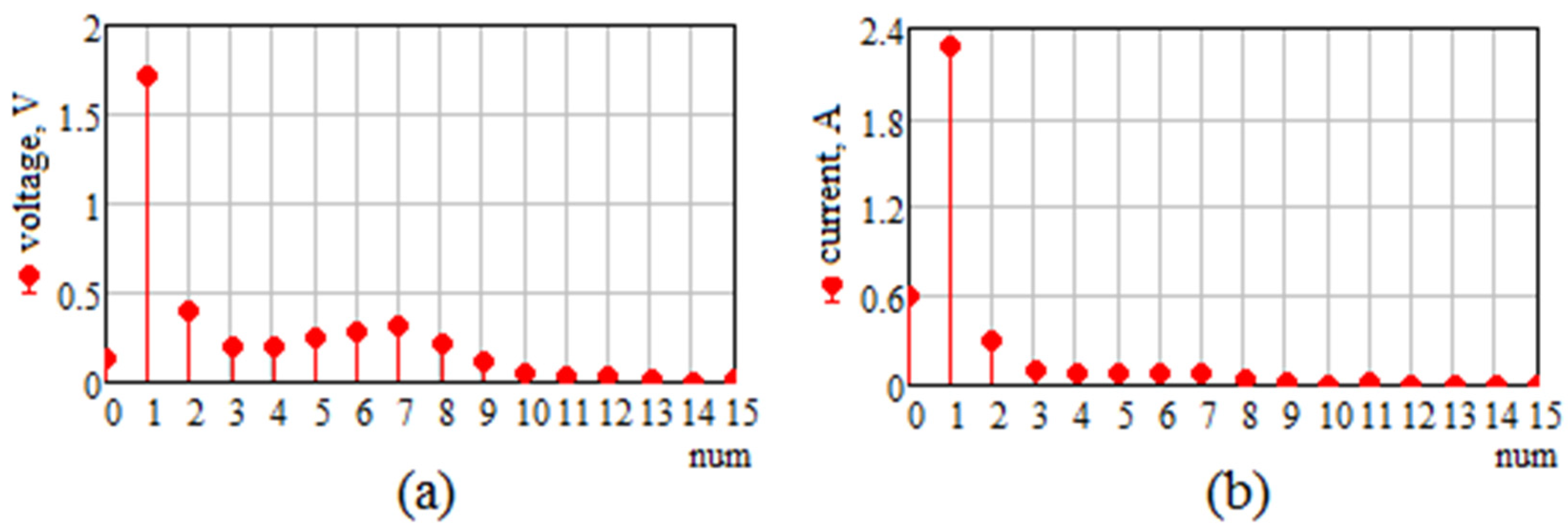
In the experiments where the supply was provided with a multi-harmonic voltage with a frequency of ≈1000 Hz, the function of this voltage and the corresponding current were decomposed into a Fourier series (
Figure 14). The first 15 harmonics were taken into account. The increase in the value of KR in the case of the layered arrangement of elementary conductors found at a current frequency of 995 Hz can be attributed to the effect of higher harmonics occurring in the supply voltage.
The occurrence of harmonics in the supply voltage, whose amplitudes constitute a significant percentage of the amplitude of the first harmonic—namely, the second and from the fifth to the eighth—leads to a corresponding increase in the harmonics of the same order in the current. The saturation of the magnetic core does not occur in these experiments.


