1. Introduction
Maximizing the energy efficiency of electric drives is a key objective in several fields, such as renewable energy applications, particularly in micro-hydropower systems, where the power availability is limited, typically in the range of 5–100 kW [
1]; although this range is not universal, the speed is low, and the energy conversion has to be as effective as possible [
2].
In such systems, induction generators, particularly conventional three-phase ones, are widely used due to their robustness and simplicity [
3]. However, these machines are not fault-tolerant, which is a crucial requirement to ensure reliable and efficient operation.
When implemented in multiphase configurations such as six-phase generators, they offer superior fault-tolerance, maintaining operation even with the loss of up to three phases [
4,
5]. This capability is essential for autonomous operation in remote environments. They also provide more balanced power distribution, reduced torque pulsations, lower stator copper losses, and decreased rotor harmonic components, making them well-suited for energy generation in constrained environments.
Nevertheless, when a fault occurs, power oscillations appear, which require appropriate control strategies to attenuate and ensure stable operation [
4].
In energy generation systems such as micro-hydropower, enhancing only the performance of the generator is not sufficient. Indeed, minimizing the losses in all the conversion chain components, including the converters, the generator, the mechanical transmissions, or the grid, is essential to improve overall system efficiency. While advances in materials and design have helped to reduce these losses, significant losses still occur in the converters and the generators, and both depend largely on the implemented control strategy [
6].
One key challenge in improving energy conversion efficiency is minimizing total electrical losses, including stator and rotor copper, iron, and converter losses, particularly in inverter-fed drives. Furthermore, the converter losses become significant in inverter-powered drives operating at high frequencies. In this way, a comparative study [
7] of switching losses in two-level and multilevel inverters highlights the necessity of optimizing these losses for high-frequency multiphase systems. Indeed, the converter losses are mainly of two types [
8]: conduction losses when power devices (e.g., IGBT or MOSFET) conduct current, and switching losses, occurring during ON/OFF transitions due to the voltage–current overlap [
9]. At high frequencies, the conduction losses become negligible, leaving switching losses as the dominant factor, especially with multiphase systems. The details of the mechanisms of conduction and switching losses in MOSFETs and their impact on the efficiency of power supplies are studied in [
10].
While traditional control strategies, such as Indirect Rotor Field-Oriented Control, are commonly employed, they rely on fixed magnetizing current values and do not adapt to varying torque load or speed conditions [
11]. This results in non-optimal efficiency, especially under partial load or variable speed operations [
12], which are common in some systems like micro-hydropower contexts.
To address this, several approaches have been proposed in the literature. These methods are generally categorized into three types: model-based methods, search-based methods, or self-optimizing methods [
13] and hybrid methods that combine elements of both [
14]. Among the model-based approaches, Loss Model Control (LMC) [
15] computes the optimal magnetizing current based on an analytical model of losses, such as copper and iron losses. It offers the advantage of fast response and good accuracy when the machine and the loss parameters are well identified. However, it can be sensitive to modeling errors and parameter uncertainties [
15]. The Maximum Torque per Ampere (MTPA) strategy [
16] minimizes the current magnitude for a given torque, which effectively reduces copper losses but ignores losses such as iron and switching, limiting its overall efficiency, particularly at low load torque.
In contrast, experimental search methods, such as Search Control (SC) [
17] or Minimum Loss Search (MLS), do not require any knowledge of the machine or its losses, making them robust to uncertainties. However, their main drawback is the slow convergence, which makes them unsuitable for applications requiring fast dynamic response [
18].
LMC has already been applied in electric vehicles and energy generation [
15], considering only copper and iron losses. However, in multiphase applications that need additional converters and in constrained, lightly loaded environments where switching losses become significant, it becomes necessary to go further and explicitly include these losses in the optimization. This consideration forms the foundation of the contribution presented in this work.
In this way, this paper introduces an extended real-time Loss Model Control (LMC) strategy adapted for six-phase induction generators (6PIGs) operating in both healthy and faulty modes. The proposed models include a complete loss model explicitly accounting for switching losses of the converter often omitted in prior works in the conventional LMC.
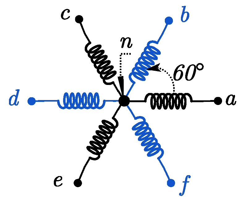
In this paper, a 24 kW–230 V–125 rpm–12 poles pair 6PIG built in our laboratory, coupled to a gearmotor to simulate a wind turbine or microhydraulic turbine, is used to validate the proposed strategy. The high number of poles reduces the rated speed of the generator and simplifies or eliminates the gearbox, which is responsible for the mechanical faults and improves the robustness against electrical and mechanical faults.
Section 2 will provide a brief overview of the overall system architecture, while
Section 3 will focus on the modeling and control of the generator for both healthy and faulty modes. The proposed control strategy is then studied in
Section 4. Lastly,
Section 5 will be dedicated to the results and discussions, followed by the conclusion in
Section 6.
2. System Overview
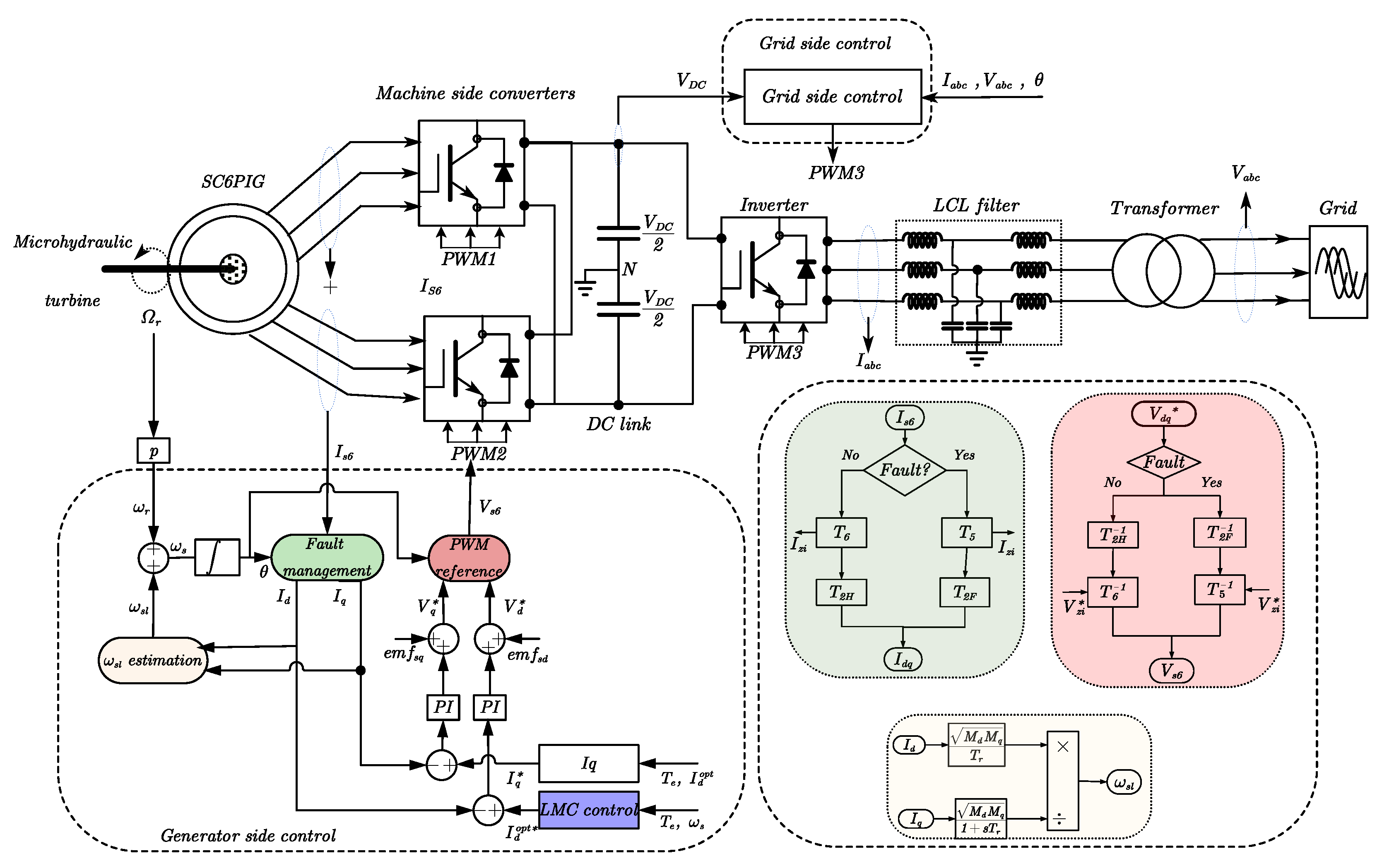
Figure 1 shows the control of the whole system structure of the proposed control scheme in healthy and faulty operations. The following system consists of:
- ▪
A squirrel cage six-phase induction generator for power generation.
- ▪
A back-to-back converter that links the generator and the grid and/or local load to extract and inject power. Two three-phase voltage source inverters (VSIs) are used to connect a six-phase generator, and the VSI used in the grid side is connected to the load and/or the grid through an LCL filter.
- ▪
The control blocks of both the generator and the grid side.
This study focuses on the generator side by controlling both healthy and faulty operating modes based on the field-oriented control (FOC), while integrating the proposed extended LMC strategy.
The blocks related to fault management, slip speed estimation , and PWM reference generation are highlighted on the right-hand side using corresponding colors. Their operation is as follows: When the machine operates in a healthy mode, the and matrices from the fault management block (in green) are used to determine the currents in the rotating reference frame. To obtain the voltage references in this case, and matrices from the PWM reference block (in red) are applied. In the event of a fault (using a switch), such as one open phase (“a”) in this study, the corresponding system branch is automatically activated to adapt the control strategy accordingly.
The magnetizing current block (in pink) is derived using Equation (32) for conventional LMC and Equation (36) for the proposed extended LMC, while the quadrature current (in white) is derived using Equation (34).
All the proposed systems presented in this paper have been first modeled and simulated using MATLAB/simulink® software (R2024b).
4. Extended Loss Model Control
The aim of the LMC method consists in minimizing the total losses of the generator by dynamically adjusting the excitation current Id, according to the requested torque Te. Then, the proposed control will take into account switching losses in addition to generator power losses.
The total power losses in an induction generator and converter can be expressed as in Equation (18):
where
,
,
, and
represent the copper, core, mechanical, and switching losses, respectively, associated with the winding resistance, magnetic effects, and rotor motion.
For clarity, all variables and parameters used in the equations are summarized in the nomenclature provided in
Appendix A.
In steady state, the stator and rotor copper losses are expressed as follows:
The core losses consist of eddy current losses and hysteresis losses and are given by:
where
is the air-gap flux linkage, and
and
are the hysteresis and eddy current loss coefficients. The air-gap flux linkage can be expressed in terms of the current components as follows:
In the Indirect Rotor Flux Oriented Control strategy, the rotor current components in the rotating frame are expressed as in (22), and the air-gap flux linkage components are expressed as in Equation (23):
As a result, the core losses can be written as follows:
The mechanical losses are given as a function of the rotor speed
, the dry friction torque
, and the viscous friction coefficient
:
In previous studies conducted on the same test bed [
15], the switching losses of the used converter have been determined as follows:
where
Then, the full expression of the total power losses in steady state, including all components, can be written as follows (28):
This expression can also be reformulated as a function of the synchronous speed and the stator current components in the dq frame, as shown in Equation (29), since the mechanical losses are not electrically controllable through the IRFOC strategy and depend on the machine conditions [
16].
4.1. Classical Loss Model Control
In the conventional LMC, only electrical power losses localized on the generator side are considered as follows:
where the coefficients
and
are defined as follows:
The optimal magnetizing current
is then given by Equation (32). It is proportional to the quadrature current
by the optimization factor, which depends on the angular speed
.
4.2. Proposed LMC
By taking into account the switching losses of the converter, the global cost function of both the generator and converter is as follows:
The quadrature current
obtained from the electromagnetic torque is then given by:
Using (34) to eliminate
in (33), the optimizing losses function is as follows:
The cost function
given in (35) is not easily solvable analytically as in the aforementioned classical LMC. Therefore, the proposed method will proceed with an online numerical solution using algorithms:
Table 2 summarizes the key differences between the three control strategies used in this study with respect to types of losses included in their optimization models and the nature of the optimization (static or dynamic). The proposed LMC extended strategy differs from conventional LMC by incorporating switching losses and performing dynamic current adjustment for real-time loss minimization.
5. Results and Discussions
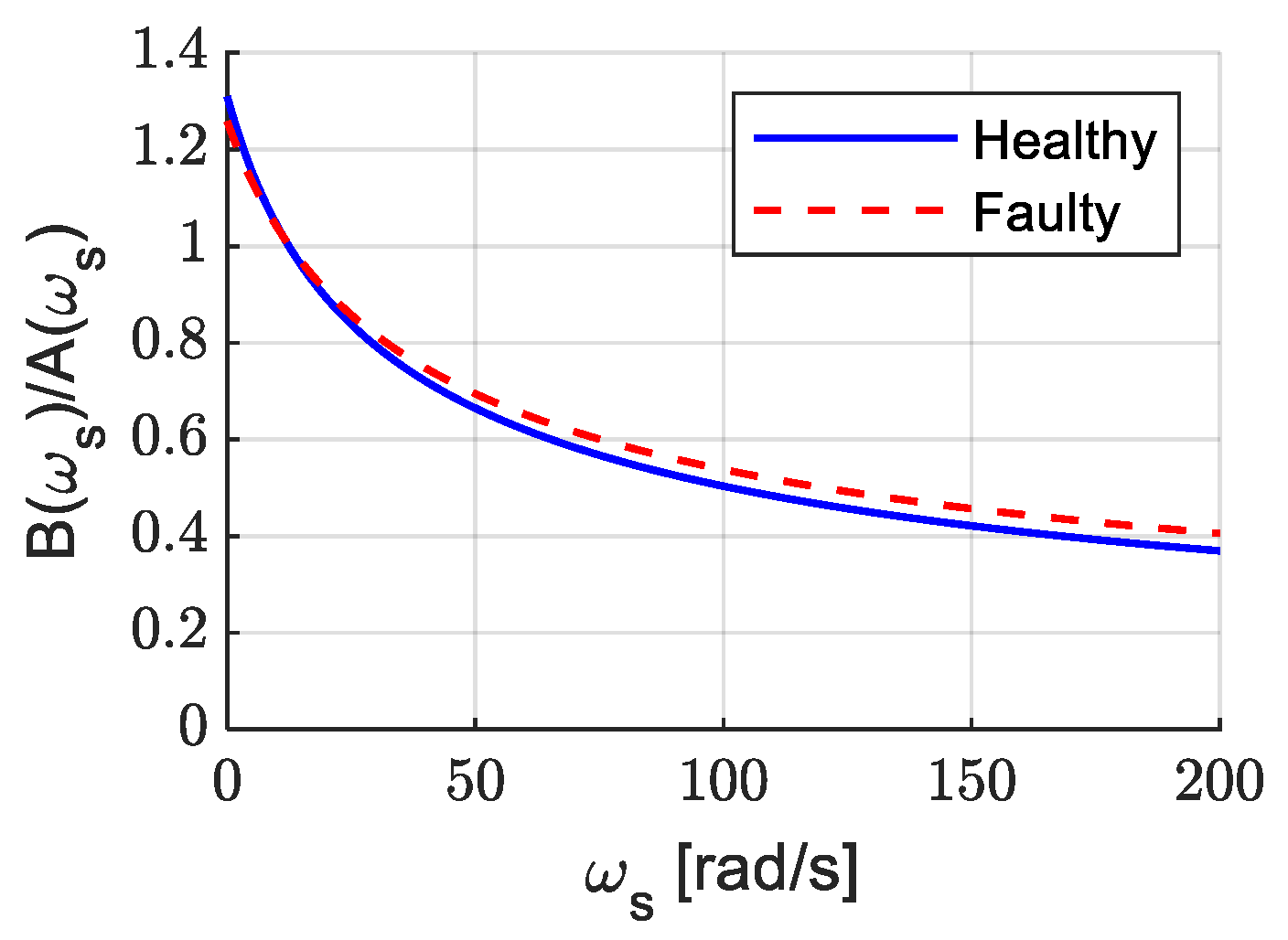
Equation (32) provides the expression of the optimal direct axis stator current
obtained from the analytical minimization of the total loss function defined in Equation (30). The factor
represents the optimal ratio between the magnetizing and the quadrature axis currents that reduces losses in classical LMC. It balances the components
and
of the losses given in Equation (31). Both of these components depend on the synchronous speed
The factor enables dynamic adjustment of the excitation current to optimally distribute losses according to the operation speed.
Figure 3 shows how the optimal factor evolves with
in healthy and faulty modes.
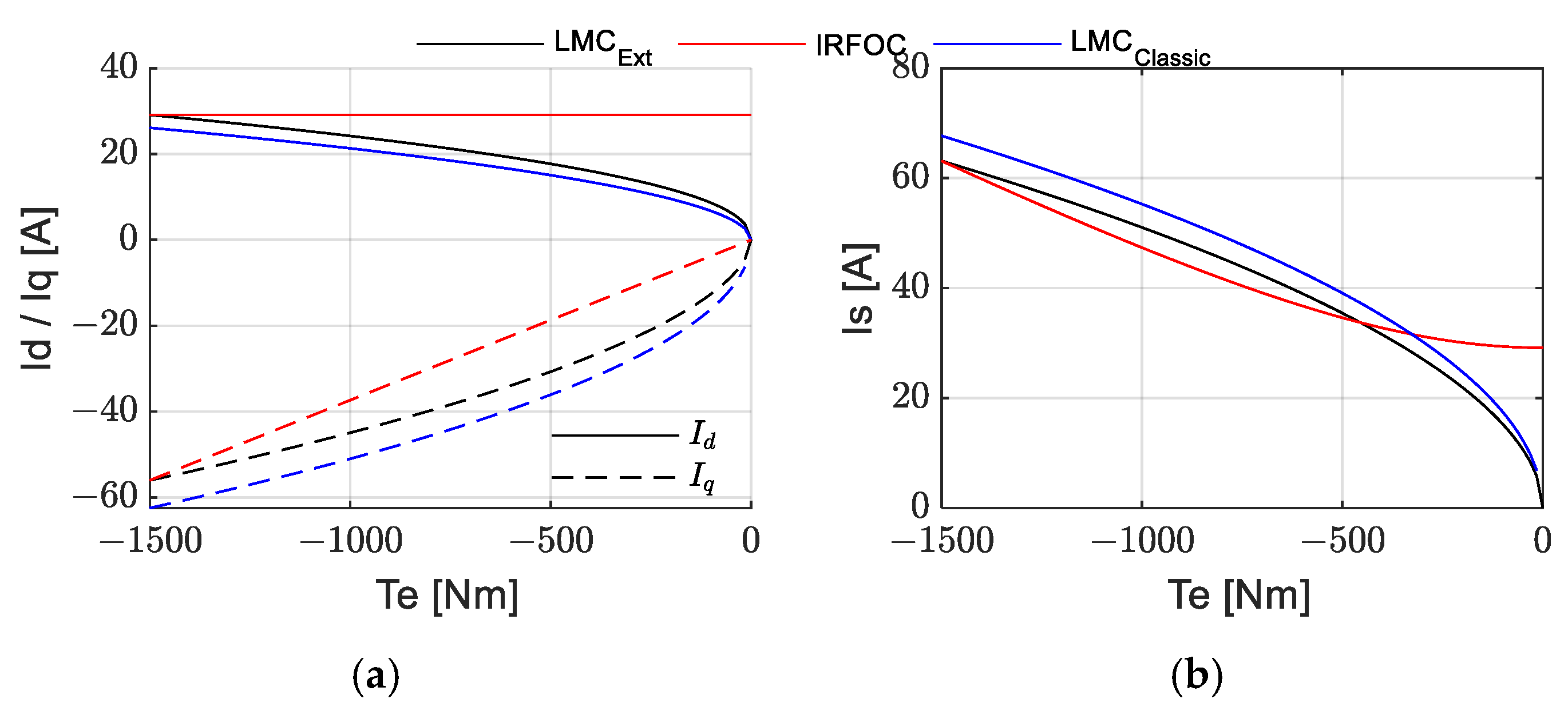
The optimized direct axis current obtained using the extended LMC is shown in
Figure 4. This figure includes the stator current obtained by the optimization method and compares it to the classical and the IFROC ones. The theoretical analysis confirms that LMC_Ext achieves an optimal compromise between Id and Iq to minimize losses. Unlike IRFOC control (red), which keeps Id constant and maximal, and LMC_Classic (blue), which overly reduces Id, the proposed LMC_Ext (black) intelligently adjusts Id with respect to torque. This avoids excessive growth in Iq and hence the stator current Is, leading to globally lower losses, especially at medium–high torque.
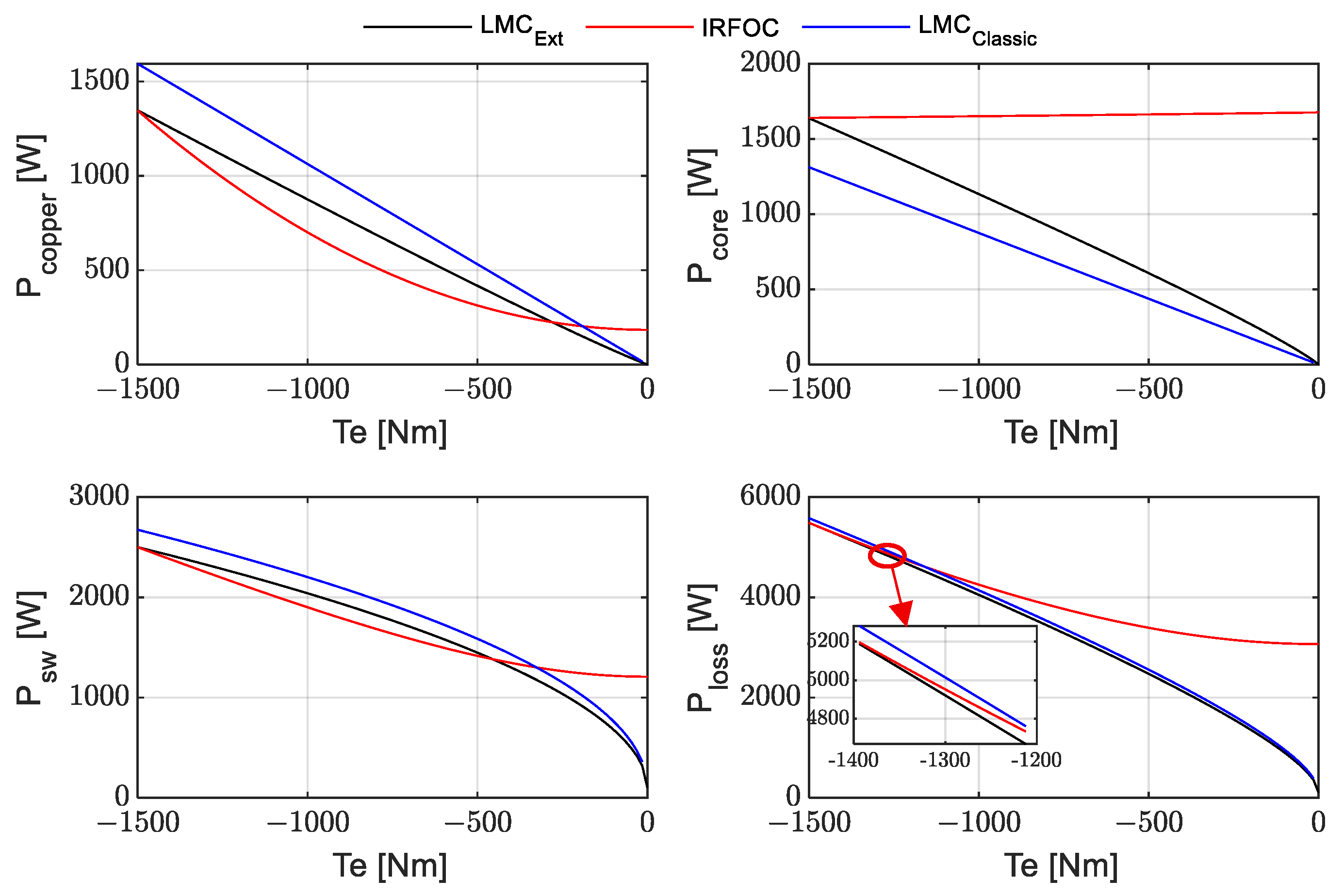
The LMC_Ext (black) strategy achieves the lowest total losses thanks to an effective reduction in core losses and a well-balanced current distribution. The conventional LMC_Classic (blue) shows a better optimized core losses reduction, but this is not sufficient and optimal in the entire system. Under IRFOC control (red), copper losses are minimized, but core losses increase, making it non-optimal at low and medium load torque. The zoomed-in area (bottom-right) in
Figure 5 highlights the increasing advantage of LMC_Ext and the non-optimal control of LMC_Classic at high torque.
This color convention (black for LMC_Ext, blue for LMC_Classic, and red for IRFOC) is maintained throughout all the figures below in this paper, as indicated in the legend of
Figure 5.
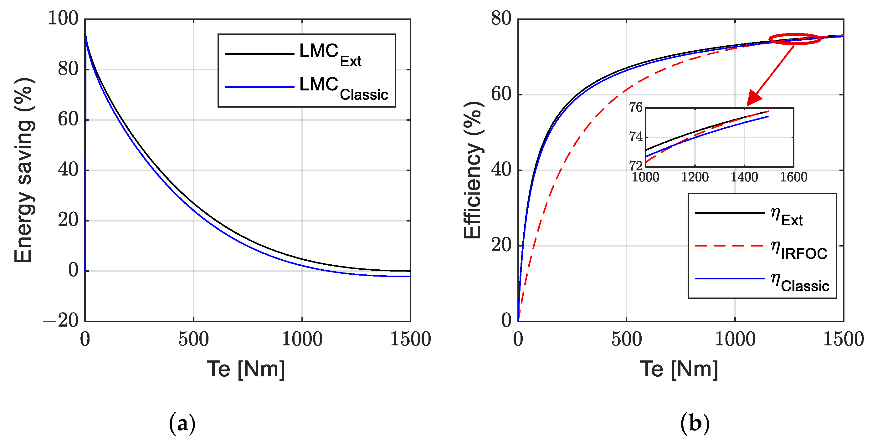
As shown in
Figure 6, LMC_Ext shows the highest energy saving (
Figure 6a) at low load torque due to reduced core losses from minimizing the excitation current Id. This advantage decreases at high torque as all strategies tend to converge toward optimal behavior. The efficiency trend in (
Figure 6b) confirms this since LMC_Ext remains slightly superior to LMC_classic due to a better ratio Id/Iq trade-off, while IRFOC control suffers from high core losses at low torque but improves at high torque load, as shown in the zoom area.
5.1. Simulation
The simulation results presented in this section were obtained using MATLAB/Simulink® software.
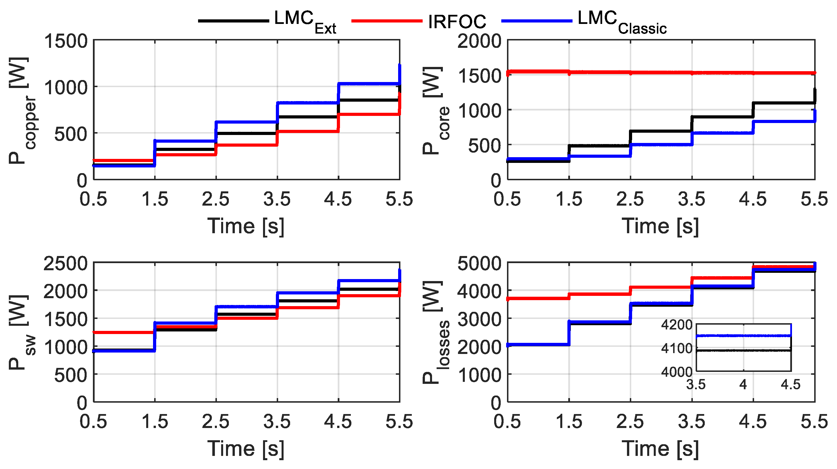
Figure 7 depicts the copper, core, switching, and total losses for different torque references (−200 N·m, −400 N·m, −600 N·m, −800 N·m, and −1000 N·m) with the three strategies (black curves for extended LMC, blue for classical LMC, red for IRFOC).
As illustrated in
Figure 7, the proposed LMC_Ext strategy consistently reduces total losses compared to the conventional ones LMC_Classic and even more so relative to IRFOC. This improvement is mainly due to a significant reduction in core ore iron losses achieved through better control of the magnetizing current Id. Although LMC_Ext may show slightly higher copper losses than IRFOC, the overall balance between copper, core, and switching losses makes it globally more efficient.
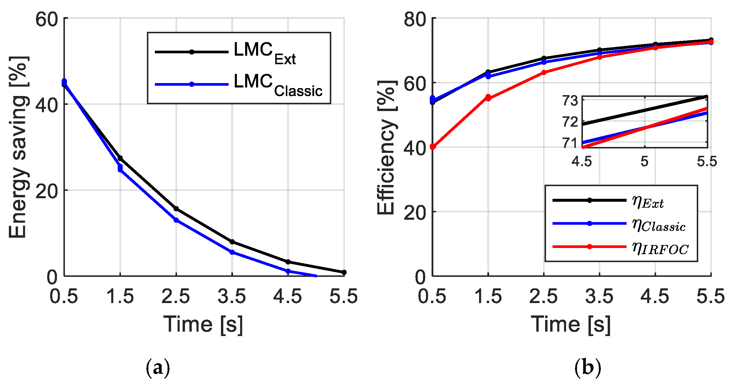
Energy savings presented in
Figure 8a are observed at large torque levels with particularly high gains at low and medium torque loads, resulting in a higher efficiency than both the LMC_Classic strategy and IRFOC control.
It can be noticed that, at high torque, LMC_Classic tends to select a suboptimal Id/Iq compromise by reducing the magnetizing current Id too much, which increases Iq and rotor and core losses. In contrast, the IRFOC control, with a maximized Id, naturally approaches optimal performance in this range of values. As a result, LMC_Classic may become less effective, even showing negative energy gains in some cases.
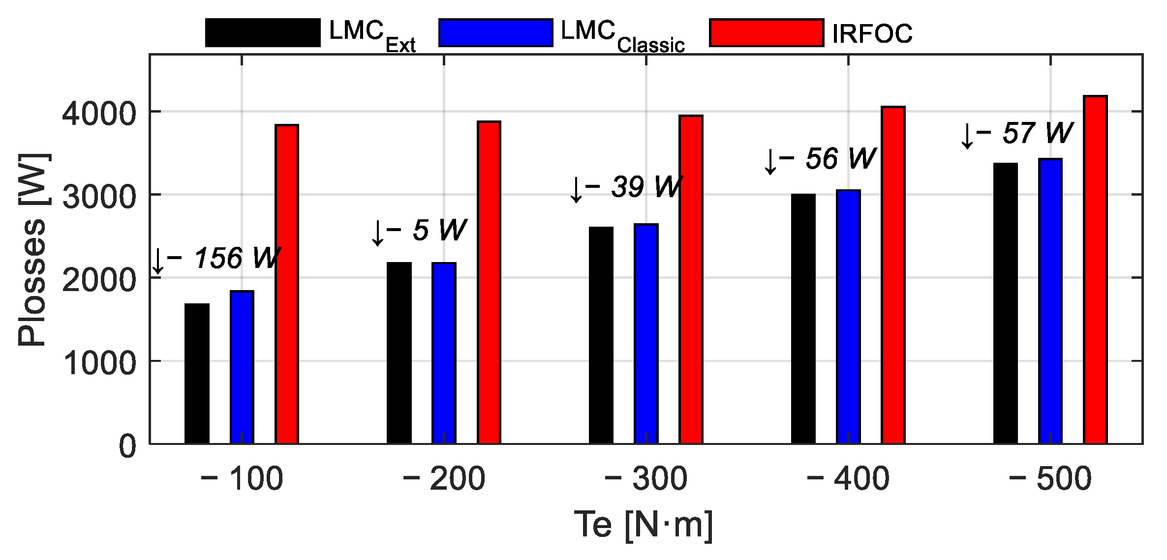
Figure 9 shows the performance of the three control strategies under one missing phase operation. The LMC_Ext strategy (black bar) remains globally slightly efficient than LMC_Classic (blue bar) even under fault conditions. The difference in total power losses is especially significant at low torque load, for instance reaching 156 W at −100 N·m, which highlights the better adaptability of LMC_Ext in faulted mode. Although the gap narrows at higher torque levels, LMC_Ext maintains a slight advantage, confirming its robustness in faulty operation. Despite the low load torque request, losses become considerable in faulty mode, highlighting the importance of an adaptive control strategy such as LMC_Ext.
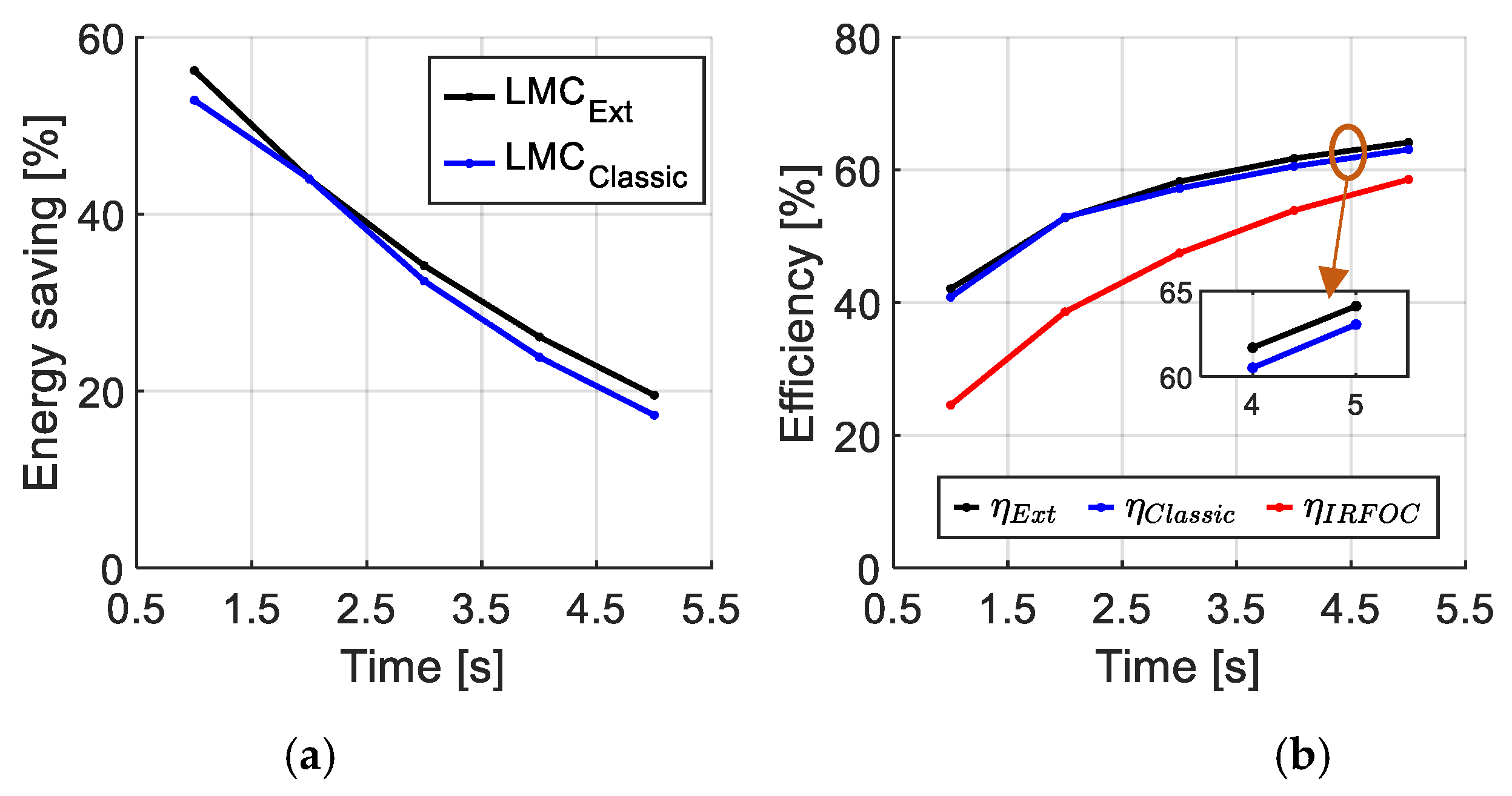
Figure 10 shows that in faulty mode, the energy saving delivered by LMC_Ext remains significant across the entire torque range, although slightly lower than in healthy mode. Regarding efficiency, LMC_Ext has the best performance across the range. Overall, LMC_Ext proves to be the most robust and energy-efficient strategy even under fault conditions. In the faulty mode case, the requested torques are kept low because the phase currents increase significantly under fault conditions. This limitation is intentional, aiming to prevent excessive current stress on the remaining healthy phases.
Table 3 presents the efficiency results under both healthy and faulty modes for different torque values. The column in grey quantifies the improvement achieved by the proposed LMC-Ext strategy compared to both IRFOC and classical LMC strategies. The comparison highlights that the proposed LMC_Ext strategy provides a significant efficiency gain over IRFOC, especially under low and medium torque levels in both healthy and faulty modes. Although the gain over classical is more moderate, it remains notable and consistent, particularly at low load conditions where switching and core losses are more pronounced. This confirms the benefit of adjusting the excitation current while taking switching losses into account. The blue column represents the losses’ reduction (gain) achieved by the proposed LMC_Ext strategy compared to IRFOC and LMC_Classic. The results show that LMC_Ext consistently reduces total losses, particularly at low and medium torque levels and in faulty conditions, confirming its effectiveness for real-time energy optimization.
5.2. Experimentation
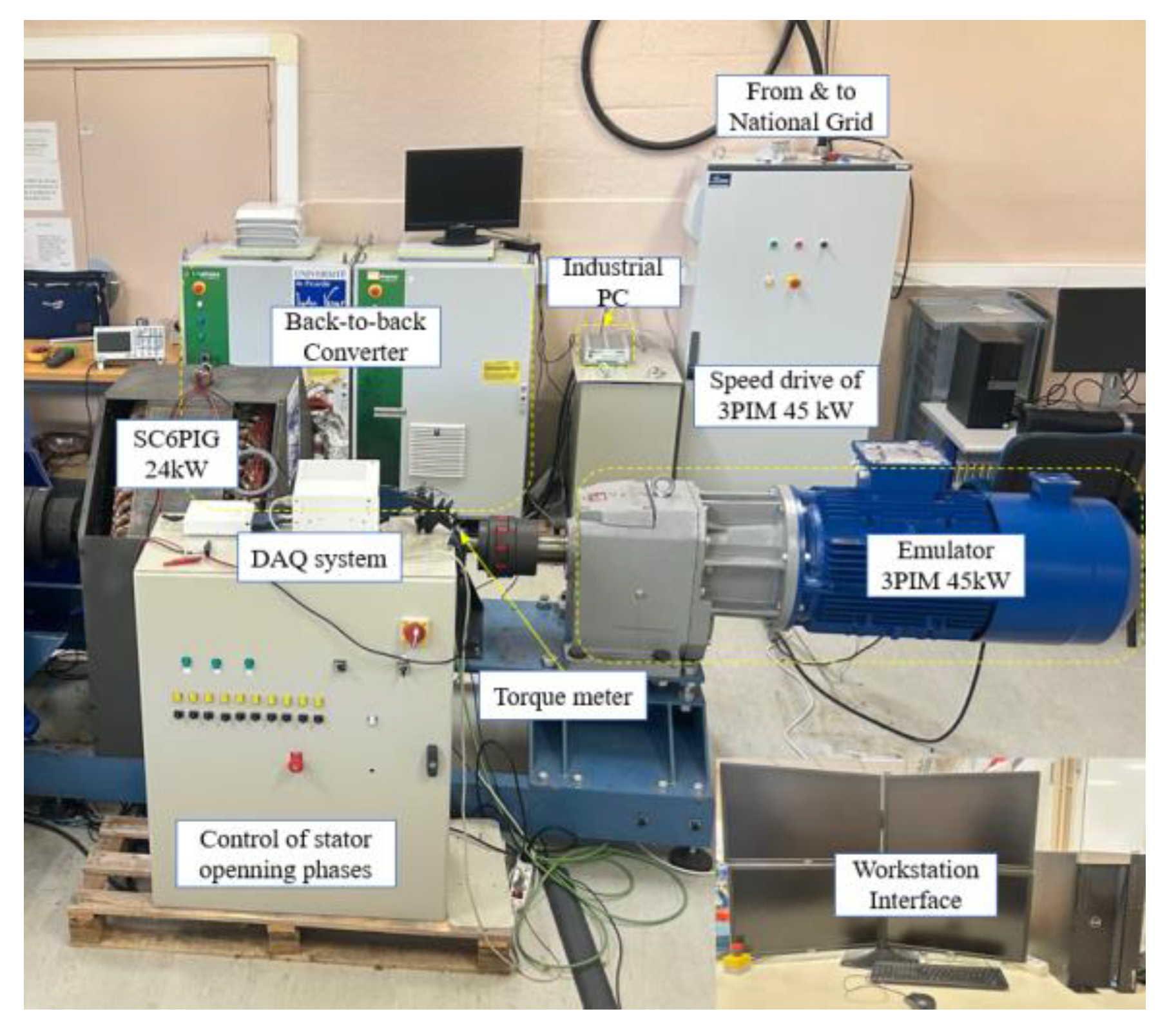
Figure 11 illustrates the test bench developed to replicate the behavior of a micro-hydraulic or a wind energy system. The setup includes a gearmotor composed of a 45 kW three-phase induction machine equipped with a gearbox. This system emulates the kinetic energy of flowing water in micro-hydropower or wind force in wind energy applications. The gearmotor is controlled by a LEROY SOMER
® (Angoulême, France) variable speed drive using a V/f (Voltage/frequency) control strategy. This drive allows the generator to operate within a speed range of 0 to 133 rpm. The position is measured via an optical encoder with 4096 pulses per revolution. The gearmotor is coupled to a torque sensor with data acquisition performed using a MAGTROL system (Model 3411), Paris, France and also coupled to the squirrel cage six-phase induction generator (SC6PIG) rated at 24 kW–125 rpm–24 poles–230 V. Electrical power is extracted via two 3-phase back-to-back converters each with their dc link connected from the brand Triphase
® (Holsbeek, Belgium), controlled in real time by an industrial PC from Triphase
®, which runs the compiled control program from MATLAB/Simulink
® software via the workstation. Measurements are carried out at a frequency of 8 kHz, enabling detailed current and power analysis through high-speed data acquisition using a National Instruments
® DAQ system (Paris, France).
Figure 12 represents the experimental power losses under healthy operating conditions with the three control strategies and different references of torque in the same conditions as in simulation (
Figure 7). The experimental results (
Figure 12) are really close to the simulation ones (
Figure 7) and validate the theoretical analysis. They also confirm the best performance of the LMC Ext strategy by minimizing total power losses. At the same torque
Te = −200 N·m, losses in faulty mode (
Figure 12 at 1.5–2.5 s) are significantly higher than in healthy mode (
Figure 7, 0.5–1.5 s) due to current redistribution and added stress on remaining phases. Yet the proposed LMC_Ext strategy maintains the lowest losses in both modes, demonstrating both its efficiency and robustness under faulted conditions.
In the zoom area of
Figure 12, we can observe ripples of the order of a few tens of watts (±50), which are relatively minor and do not affect the overall trend or the validity of the experimental results. This behavior is expected and attributed to several practical factors, such as measurement noises, nonlinearities in the power components, and other imperfections.
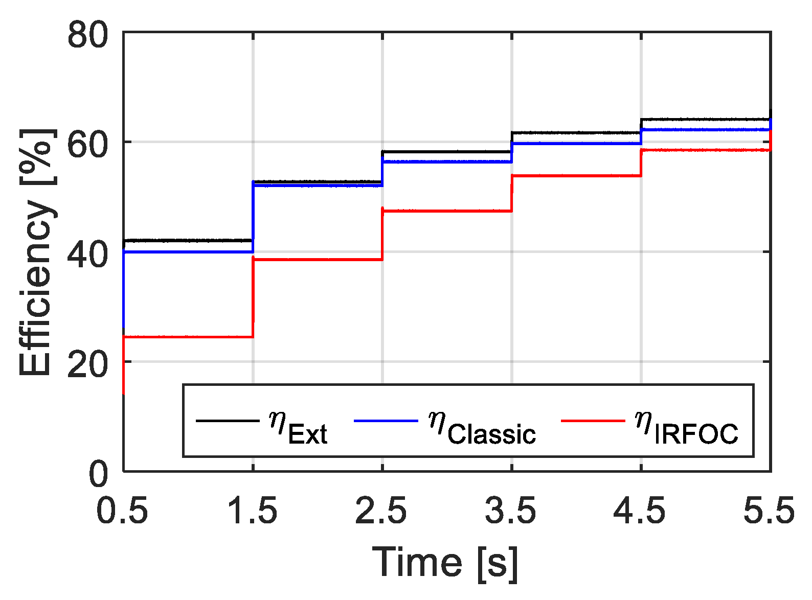
Figure 13 depicts the energy efficiency under faulty conditions (one phase missing) with the three control strategies in the same torque conditions. This experimental test confirms the effectiveness of the proposed LMC_Ext control compared to the classical LMC and IRFOC under fault conditions.
Table 4 presents the experimental results that validate the effectiveness of the proposed control strategy. Compared to IRFOC, LMC_Ext shows clear efficiency improvements, particularly at low to medium load torque, even under faulty conditions. The gain compared to LMC_Classic is moderate but remains constant, demonstrating that the dynamic adaptation of the magnetizing current is beneficial in real hardware. Unlike the simulation, where the behavior is idealized, the experimental data confirm that LMC_Ext maintains its performance advantage despite real-world imperfections, reinforcing its practical applicability for energy-aware control in both healthy and faulty modes, with differences for some values.
The proposed control strategy offers a good compromise between core and switching losses by choosing an optimal magnetizing current value, effectively reducing total power losses. This approach also leads to lower stator current levels, resulting in reduced stress on a converter. As a consequence, it decreases the converter operating temperature, protecting the semiconductor components and contributing to a longer lifetime.
6. Conclusions
The proposed study demonstrated the effectiveness of an extended loss model control (LMC_Ext) strategy for improving the efficiency of a six-phase induction generator in both healthy and faulty operating conditions. By including switching losses in the optimization process and dynamically adjusting the magnetizing current Id, the proposed method achieves consistent reductions in total power losses.
Simulation and experimental results confirm that LMC_Ext consistently outperforms both the classical LMC and the IRFOC approaches, particularly at low and medium torque loads, where energy savings are most sensitive to excitation current tuning. In simulation, the gain over IRFOC is particularly significant, with notable improvements in both efficiency and energy savings. The experimental results confirm this trend, albeit with slightly higher margins. This difference can be attributed to practical imperfections, including measurement noises, system non-linearities, and inherent imperfections of components, which are not fully captured in the model.
Despite these non-idealities, the experimental validation confirms that LMC_Ext remains robust and beneficial. Its ability to maintain superior performance even under faulted conditions illustrates its real-time applicability and resilience. These findings highlight the importance of considering dynamic losses in control design and open perspectives for the application of this approach in higher power and more complex multiphase systems. However, finding the optimal point online requires additional computation, albeit manageable in real time.
Several future directions are envisioned to extend this work. First, a sensitivity analysis will be conducted on the key machine parameter (e.g., Rs, M, or Lr) to evaluate the robustness of the proposed strategy under model uncertainties. Further studies will also explore additional fault scenarios, such as inter-phase short circuits and voltage unbalance, to reinforce the fault-tolerant capabilities of the system. Moreover, a comparative analysis with other optimization strategies, including Minimum Loss Search (MLS), Maximum Torque Per Ampere (MTPA), and intelligent control approaches (e.g., fuzzy adaptive control), is currently under development. Finally, a broader system-level assessment will be pursued, considering turbine–generator interaction load variability and possible integration with energy storage to evaluate the global impact of the proposed control on micro-hydropower system efficiency.


