Article

Development of a Surface-Inset Permanent Magnet Motor for Enhanced Torque Density in Electric Mountain Bikes

School of Electrical and Electronic Engineering, Nanyang Technological University, 50 Nanyang Avenue, Singapore 639798, Singapore
*
Author to whom correspondence should be addressed.
Energies 2025, 18(14), 3709; https://doi.org/10.3390/en18143709
Submission received: 9 June 2025 / Revised: 2 July 2025 / Accepted: 9 July 2025 / Published: 14 July 2025

Abstract

Electric mountain bikes (eMTBs) demand compact, high-torque motors capable of handling steep terrain and variable load conditions. Surface-mounted permanent magnet synchronous motors (SPMSMs) are widely used in this application due to their simple construction, ease of manufacturing, and cost-effectiveness. However, SPMSMs inherently lack reluctance torque, limiting their torque density and performance at high speeds. While interior PMSMs (IPMSMs) can overcome this limitation via reluctance torque, they require complex rotor machining and may compromise mechanical robustness. This paper proposes a surface-inset PMSM topology as a compromise between both approaches—introducing reluctance torque while maintaining a structurally simple rotor. The proposed motor features inset magnets shaped with a tapered outer profile, allowing them to remain flush with the rotor surface. This geometric configuration eliminates the need for a retaining sleeve during high-speed operation while also enabling saliency-based torque contribution. A baseline SPMSM design is first analyzed through finite element analysis (FEA) to establish reference performance. Comparative simulations show that the proposed design achieves a 20% increase in peak torque and a 33% reduction in current density. Experimental validation confirms these findings, with the fabricated prototype achieving a torque density of 30.1 kNm/m3. The results demonstrate that reluctance-assisted torque enhancement can be achieved without compromising mechanical simplicity or manufacturability. This study provides a practical pathway for improving motor performance in eMTB systems while retaining the production advantages of surface-mounted designs. The surface-inset approach offers a scalable and cost-effective solution that bridges the gap between conventional SPMSMs and more complex IPMSMs in high-demand e-mobility applications.

1. Introduction

Electric bicycles (e-bikes) have become a key solution in the push for sustainable, low-emission personal transport. By combining pedal input with motorized assistance, e-bikes make cycling more accessible across a range of user demographics—including commuters, long-distance riders, and those with physical limitations [1,2,3]. E-bikes now serve diverse applications such as last-mile delivery, urban commuting, recreational cycling, and off-road sports. According to recent market forecasts, global e-bike sales are expected to exceed 50 million units annually by 2025 [4], driven by urbanization, environmental awareness, and improvements in battery and motor technologies. A critical factor in the performance and user acceptance of e-bikes is the motor system. Modern e-bikes primarily use lithium-ion batteries for their high energy density, long cycle life, and low weight [1]. In terms of motor design, ongoing development efforts aim to improve efficiency, power density, and thermal stability without increasing cost or complexity [5,6,7]. Among the different motor configurations, mid-drive systems are preferred in high-performance applications, particularly in electric mountain bikes (eMTBs), due to their central placement, direct drivetrain integration, and ability to deliver high torque at low speeds [8]. In eMTBs, torque output, response time, and weight are primary design concerns [9]. The motor must deliver reliable performance on steep slopes, uneven terrain, and during frequent load changes. Mid-drive systems are well-suited to meet these demands because they offer improved weight distribution and better drivetrain efficiency compared to hub motors. However, the constraints on motor volume and weight necessitate designs that achieve high torque density within a compact envelope [10]. Recent advancements in eMTB drive systems have focused heavily on motor compactness, responsiveness, and thermal robustness. However, many commercial mid-drive units still face performance bottlenecks. Specifically, surface-mounted PMSMs (SPMSMs), despite their widespread use, struggle to deliver sufficient torque density without exceeding thermal limits under prolonged hill-climbing or high-load conditions [2]. These limitations are exacerbated by the space-constrained packaging and intermittent peak power demands typical of eMTB use. Thus, there is a growing need for motor topologies that can enhance torque output and efficiency while preserving manufacturability and mechanical simplicity.
Surface-mounted permanent magnet synchronous motors (SPMSMs) are commonly used in eMTB mid-drive systems due to their simple rotor construction, ease of manufacturing, and cost-effectiveness. However, their lack of reluctance torque contribution limits torque density and efficiency, particularly under high-load or high-speed conditions. Interior PMSMs (IPMSMs) address this limitation by introducing rotor saliency, enabling improved torque production and field-weakening capability, but often at the expense of increased rotor complexity, reduced mechanical robustness, and higher manufacturing costs [11]. To address these trade-offs, this paper investigates a surface-inset PMSM topology as a practical compromise between the structural simplicity of SPMSMs and the performance advantages of IPMSMs. Although surface-inset configurations have been previously reported, their specific adaptation and optimization for mid-drive eMTB applications, where volume, weight, thermal limits, and cost constraints are critical, have not been comprehensively studied. The novelty of this work lies in the integration of geometric saliency via partial magnet burial to introduce reluctance torque, without requiring sleeves or complex rotor machining. This approach improves torque density and reduces current loading while remaining compatible with compact mid-drive packaging and scalable manufacturing.
The initial phase of this project involves a detailed analysis of a commercially available mid-drive motor that employs a Surface-Mounted Permanent Magnet Synchronous Motor (SPMSM) configuration shown in Table 1. The torque densities listed for commercial eMTB motors include the total system weight (motor + gearbox + housing), whereas the proposed prototype is evaluated in isolation (motor-only). As such, direct comparison in Nm/kg is deferred to future work involving system integration. Volumetric torque density is used here to fairly evaluate the motor design under consistent electromagnetic and geometric constraints. This motor was selected as a representative benchmark due to its widespread use in high-performance e-bike applications. It was disassembled to examine key internal components and dimensions, which are essential for replicating its design and identifying areas for improvement. The analysis begins with the derivation and application of analytical equations that describe the electromagnetic behaviour of surface-mounted PMSMs, including torque production and back-EMF characteristics. These equations form the theoretical basis for performance evaluation and inform the development of a finite element simulation model. The results of this analytical study serve as a baseline for validating simulation outputs and guiding further design modifications.

2. Electric Mountain Bike (E-MTB)

An electric bicycle (e-bike) is a light hybrid electric vehicle in which propulsion is shared between human input and an electric motor, forming a coupled human–machine powertrain. Unlike fully electric vehicles, e-bikes require system-level coordination between rider effort, electric assist, and drivetrain dynamics. The performance, responsiveness, and efficiency of an e-bike depend not only on the electric motor but also on how it is integrated into the overall mechanical and electrical architecture.

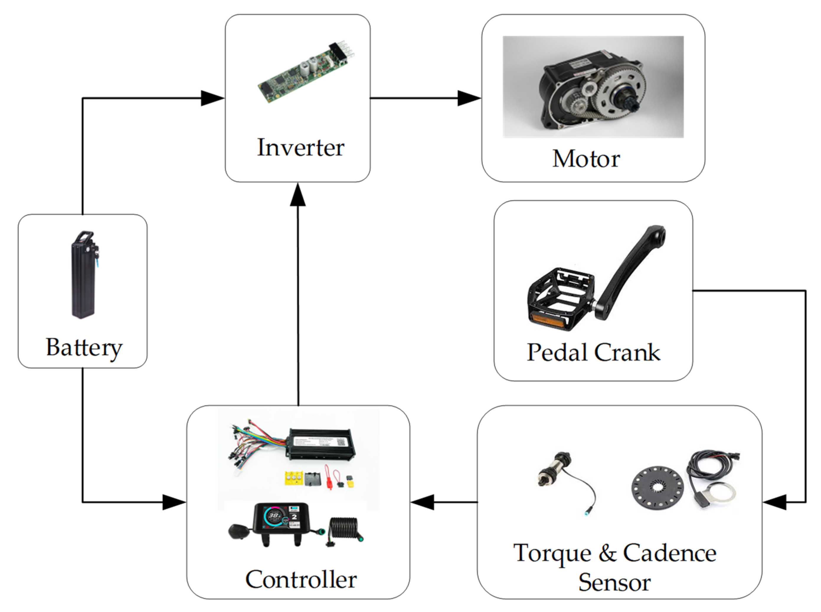
2.1. System Overview

The e-bike electrical system typically consists of five interdependent subsystems, as illustrated in Figure 1.
  • Battery Pack: Supplies DC electrical energy, typically using lithium-ion cells (36–48 V), which defines the motor’s voltage envelope and energy autonomy;
  • Power Converter (Inverter): Converts DC to three-phase AC and regulates current waveform, enabling real-time torque control via modulation strategies;
  • Controller Unit: Processes sensor data (pedal torque, cadence, speed), implements field-oriented control (FOC), and manages user-selectable assist levels;
  • Torque and Cadence Sensors: Mounted near the pedal crank, these sensors detect rider effort and pedaling rate. The measured torque and cadence signals are transmitted to the controller to determine the level of electric assistance required, enabling responsive and proportional support;
  • Electric Motor: Converts electrical energy into mechanical torque and assists the rider through one of several integration strategies.

2.2. Motor Integration Configurations

The positioning of the electric drive unit in an e-bike architecture significantly impacts mechanical integration, torque delivery, rider perception, and system-level trade-offs such as thermal management, weight distribution, and drivetrain stress. Three primary motor placement strategies are currently adopted across commercial e-bikes: front hub motors, rear hub motors, and mid-drive motors. Each configuration interacts differently with the bicycle’s mechanics and control strategy, and the choice is largely application-specific.

2.2.1. Front Hub Motors

Front wheel hub motors are mounted at the front axle and operate independently from the bike’s primary drivetrain. This layout simplifies installation and maintenance, making it popular in retrofitting conventional bicycles into electric-assist models. The independent drive also allows motor torque to be applied without modifying the pedal drivetrain. However, front hub systems shift the centre of gravity forward, which can affect steering sensitivity and front-wheel traction. On loose or uneven surfaces, the likelihood of wheel spin increases, especially during acceleration or uphill starts. This makes front hub motors less suitable for off-road or high-power applications such as eMTBs.

2.2.2. Rear Hub Motors

Rear hub motors are integrated at the rear axle, providing drive torque directly to the rear wheel. This configuration typically offers better traction than front-mounted systems due to the natural weight bias toward the rear. It is also better suited for single-speed or derailleur-based drivetrains, especially in commuter or city e-bikes. Nevertheless, placing the motor at the rear may affect weight balance, especially when combined with a rear-mounted battery or cargo load. In eMTBs, rear hub motors limit suspension design flexibility and make wheel servicing more complex due to the added weight and wiring at the hub.

2.2.3. Mid-Drive Motors

Mid-drive motors are centrally mounted near the bottom bracket and transmit torque through the chainring, leveraging the bike’s gears. This design enables efficient torque transfer, particularly useful for steep climbs or technical off-road conditions where torque multiplication is critical. It also offers improved weight distribution and a low center of gravity, enhancing handling and maneuverability. Mid-drive systems allow the motor to operate within a narrower speed range while the bike shifts gears, improving energy efficiency and thermal stability. However, they impose higher mechanical loads on the drivetrain and require dedicated frames or reinforcement, increasing system integration complexity and cost. Despite this, mid-drive systems are the dominant choice for performance-oriented eMTBs due to their superior climbing capability and torque response.

3. Analytical Modelling

This section presents the key analytical equations used to model and evaluate the performance of a surface-mounted permanent magnet synchronous motor (SPMSM) used as the baseline reference. For this analysis, mechanical losses such as bearing friction and windage are considered negligible. Under this assumption, the motor’s electromagnetic output power is equivalent to the mechanical power delivered at the shaft. In volume-constrained applications such as e-bike mid-drive systems, the rated output power can be related to the motor’s active volume and operating speed, leading to the following formulation [27]:
P o u t = T ω = m E p h I p h P o u t = 1.7436 k w B a g a c D a g 2 L s t k ω
Here, Eph and Iph denote the effective values of the phase back-electromotive force (back-EMF) and phase current, respectively, while m represents the number of phases. The parameters Lstk and Dag correspond to the active axial length and the diameter of the machine measured from the centre of the air gap. Additionally, Bag signifies the flux density in the air gap, and ac represents the electrical loading.
The radial field component produced by the magnets can be represented as a Fourier series [28,29],
B m a g θ s , θ r , θ g = n = 1 , 3 , 5 B n r g cos n p θ s θ r
where Bn is the nth spatial harmonic component of the flux density [T], rg is the air gap radius [m], θs is the angle [mech rad] along the stator periphery, θr is the rotation angle [mech rad] of the rotor, and p is the number of pole pairs.
For machines with slotted stators, various models address slotting in electrical machines, often using conformal transformations. Slotting reshapes the air gap magnetic field in two ways. It lowers the total magnetic flux linkage per pole, described by the Carter coefficient Kc. It also changes how the flux spreads in the air gap and the magnets. A relative permeance function λag, expressed as a Fourier series, represents this distribution shift.
λ a g θ s , r g = n = 0 λ n r g cos n S θ s
where λn is the nth harmonic component of the relative permeance function, and S is the number of slots. For a slotted machine, the magnetic flux density in the air gap with the stator windings open-circuited is expressed as
B o p e n c i r c u i t θ , r g = λ a g θ s , r g B m a g θ s , θ r , r g

3.1. Cogging Torque

Calculating and reducing cogging torque in PM machines often uses either the virtual work or Maxwell stress tensor methods. This analysis applies the Fourier representation of the air gap field from the magnets, plus the relative permeance functions described earlier. The energy stored in the air gap Wairgap (in Joules), depends on the rotor angle θr as follows:
W a i r g a p θ r = l e f f r s 2 r m 2 4 μ o × 0 2 π B m a g 2 θ s , θ r , r g a v λ a g 2 θ s , r g a v d θ s
where leff is the machine active length [m], μ0 is the permeability of air [H/m], rm is the outer radius of the magnets [m], and rs is the inner radius of the stator bore [m], and the air gap radius is set at rg = rgav ≡ (rs + rm)/2. The cogging torque Tcog can be calculated as follows:
T c o g θ r = W a i r g a p θ r θ r = 1 4 μ 0 l e f f r s 2 r m 2 n = 1 n N B n N 2 λ n N 2 sin n N θ r
where N is the least common multiple (LCM) of 2p and S, and B2nN and λ2nN are the Fourier coefficients of B2mag (θs, θr, rgav) and λ2ag (θs, rgav), respectively, for a period of 2π/N.

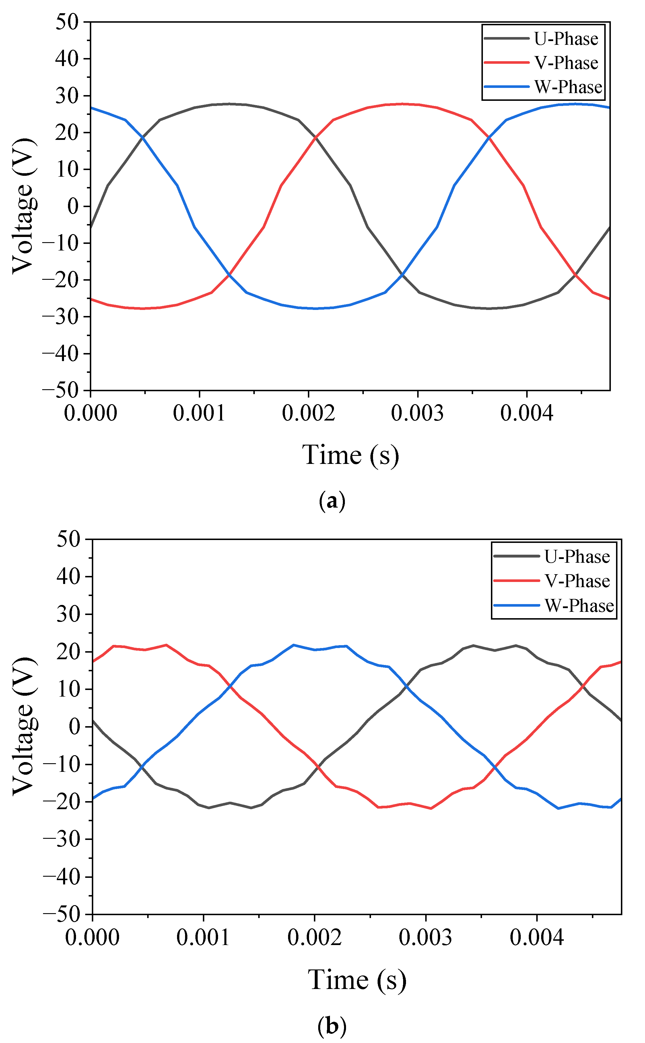
3.2. Back-EMF Calculation

The back-EMF e can be expressed in the form of a Fourier series:
e = n p ω r Φ n N s K w n sin n p θ r = n E n sin n p θ r
where ωr (=dθr/dt) is the rotor angular velocity [mech. rad/s], Ns is the number of series winding turns, Kwn is the nth harmonic winding factor, θr is the angle between the axis of phase A and the permanent magnet axis [mech. rad], and
Φ n = 2 r s l e f f λ o B n r g a v
where λo is the average value of the relative permeance function λag (θs, rgav). A preferred method for calculating the harmonic winding factors is to use the well-known winding function.

3.3. Resistance and Inductance Calculations

(1)
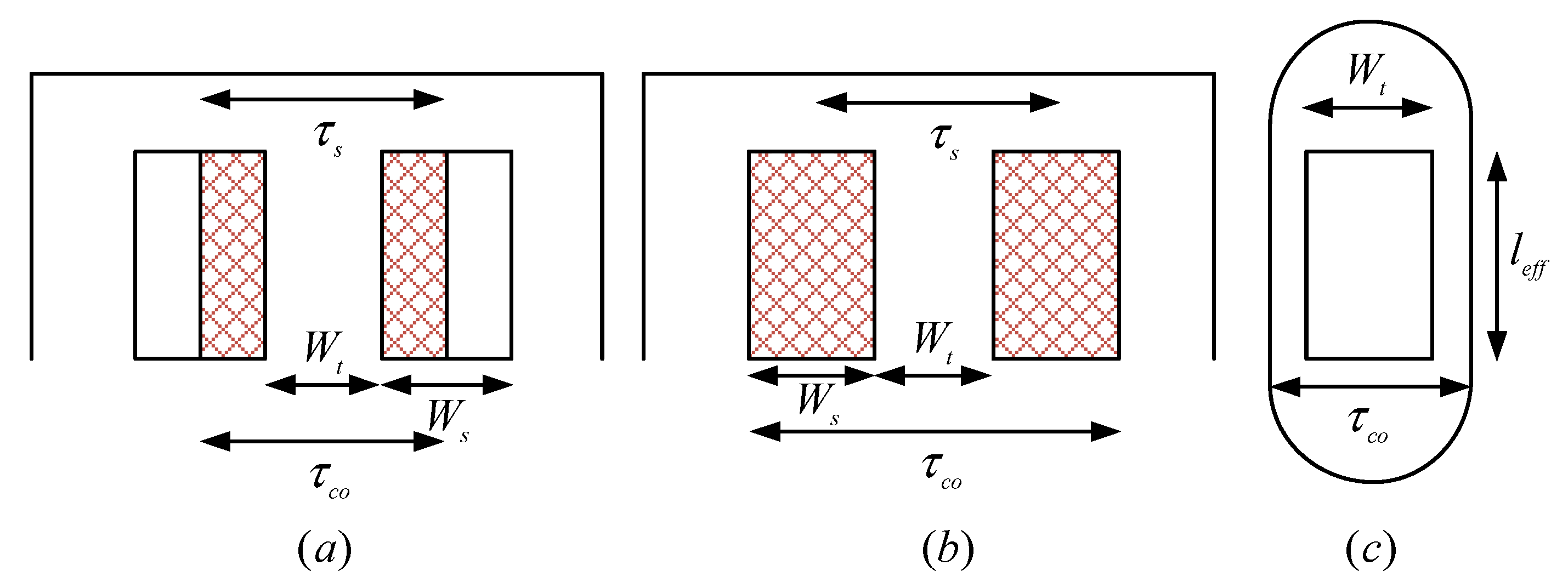
Resistance Calculations: Calculating resistance is straightforward, except for estimating the average length of the concentrated winding turns. The end turn lengths vary as the turns extend further from the tooth wall.
Figure 2a,b illustrates the layouts of a single coil in double-layer and single-layer windings. The geometric assumptions for end-turn length calculations are shown in Figure 2c. Specifically, the innermost turn is assumed to have a straight end turn, while the outermost turn has a semi-circular end turn with a width of τco, defined as follows:
τ c o = τ s   in   case   of   double - layer   winding τ c o = W s + τ s   in   case   of   sin gle - layer   winding
where τs is the slot pitch, and Ws is the slot width. The average end turn length can be calculated as follows:
l e n d , min W t l e n d , max π τ c o 2 l e n d , a v g = l e n d , min + l e n d , max 2
where Wt is the tooth width. Finally, the average turn length can be calculated as
l t u r n , a v g = 2 × l e f f + 2 × l e n d , a v g
(2)
Inductance Calculations: Machine inductances can be efficiently calculated using winding functions. For example, the phase self-inductance is given by:
L a a = μ 0 r g l e f f g 0 2 π N a 2 θ d θ
And the mutual inductance can be calculated as follows:
L a b = μ 0 r g l e f f g 0 2 π N a θ N b θ d θ
where Na (θ) and Nb (θ) are the winding functions of phases a and b, respectively, rg is the air gap radius, and g is the air gap length.

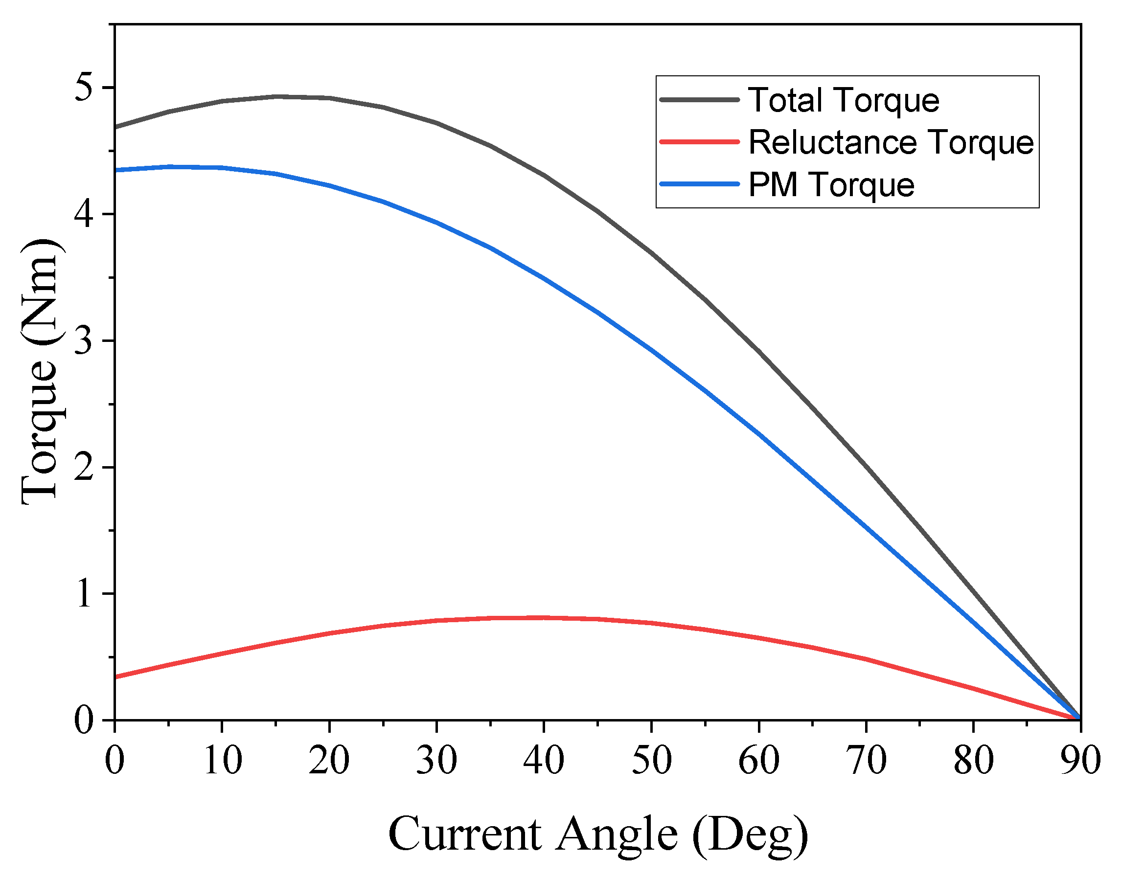
3.4. Torque Equation

The general torque equation can be expressed as follows [30]
T e m = 3 2 p ψ m i q + L d L q i d i q
where Tem is the electromagnetic torque, p is the number of pole pairs, ψm is the permanent magnet flux linkage, and iq are the direct and quadrature axis currents, Ld and Lq are the direct and quadrature axis inductances. The first part is electrometric torque; this term represents the fundamental torque contribution due to the interaction between the permanent magnet flux and the stator quadrature-axis current. This torque is directly proportional to the magnet flux and the iq current, making it the dominant torque source under normal operating conditions. The second part is reluctance torque; this arises from the variation in magnetic reluctance between the d-axis and q-axis paths. This inductance difference creates an additional torque component by exploiting the rotor saliency, effectively leveraging the magnetic anisotropy of the rotor to generate torque even when the permanent magnet flux is not directly aligned with the stator current.

4. Simulation Results

In this section, the electromagnetic performance of the baseline surface-mounted PMSM is investigated using finite element simulations conducted in JMAG. The model is configured to replicate the dimensions and winding layout of a typical mid-drive motor used in electric mountain bike applications. The simulation focuses on three primary quantities: open-circuit back electromotive force (back-EMF), electromagnetic torque under load, and cogging torque at zero current. These metrics provide a quantitative benchmark for evaluating the magnetic loading, torque production capability, and detent torque behaviour of the rotor–stator configuration. Back-EMF waveforms are computed under open-circuit conditions with constant-speed rotation and serve as a validation point for effective air-gap flux distribution and winding symmetry. Electromagnetic torque is analysed under sinusoidal current injection, assuming ideal current excitation without PWM or inverter delay effects. Cogging torque is evaluated through static torque analysis over one electrical period with no current excitation, enabling identification of torque ripple contributions due to slot–pole interaction. The geometric and material parameters used for model development are listed in Table 2.
These values were obtained through direct measurement of a disassembled reference motor and serve as the basis for simulation and comparison. Key dimensional constraints, including stator outer diameter, stack length, and air-gap geometry, were preserved in all design variants to ensure consistency across performance evaluations. In the absence of manufacturer-specified material data, standard industrial grades were assumed: N42UH sintered NdFeB magnets for the rotor and 50JN1300 non-oriented electrical steel for the stator and rotor laminations. These selections are consistent with common mid-drive motor construction practices and are sufficient to capture the dominant electromagnetic behaviour necessary for accurate performance benchmarking. While Surface Permanent Magnet (SPM) motors offer numerous advantages, they also present several challenges that must be addressed to optimize their performance. A key limitation is the lack of reluctance torque, a drawback compared to other motor types with different d-axis (Ld) and q-axis (Lq) inductances that can leverage both magnetic and reluctance torque [31]. Additionally, SPM motors have limited flux-weakening capabilities [32], which restricts their ability to operate efficiently at high speeds. The surface-mounted design also exposes permanent magnets to significant mechanical stress, potentially impacting durability. To address these issues, a surface-inset motor topology is proposed, combining the benefits of SPM motors with the ability to harness reluctance torque [33]. This approach aims to enhance torque performance, mechanical resilience, and flux-weakening capability, while maintaining the core advantages of simple construction and high efficiency. The proposed surface-inset PMSM design maintains key dimensional and electromagnetic parameters from the baseline prototype to enable a direct and consistent comparison shown in Table 2. The stator configuration of 12 slots and 7 pole pairs is preserved, along with a gear reduction ratio of 27.1, ensuring that drivetrain dynamics remain unchanged. The stator outer diameter is fixed at 91 mm, and the active axial stack length is retained at 25 mm. These constraints ensure comparability in torque density and thermal loading across configurations. A primary design modification involves a reduction in permanent magnet volume, made possible by introducing rotor saliency to enable partial reluctance torque contribution. The benchmark motor was modelled using N42UH magnets based on material assumptions from physical teardown analysis. In contrast, the proposed surface-inset PMSM utilized N48 magnets to reflect a design-optimized configuration. Notably, the total magnet volume was reduced in the proposed design due to the added contribution of reluctance torque from rotor saliency. This indicates that the observed torque improvement is not attributable solely to the use of higher-grade magnets, but arises from the combined effects of rotor topology optimization. The stator yoke thickness is set to 2.7 mm and tooth width to 5.4 mm, values selected to avoid magnetic saturation under peak loading. The tooth tip width of 7.2 mm and rotor pole arc angle of 19.3° mechanical are chosen to reduce flux leakage and limit cogging torque. A slot filling factor of 0.45 is adopted to reflect realistic winding practices, balancing copper utilization, thermal considerations, and manufacturability. These parameters define the reference conditions under which the proposed rotor topology is evaluated.

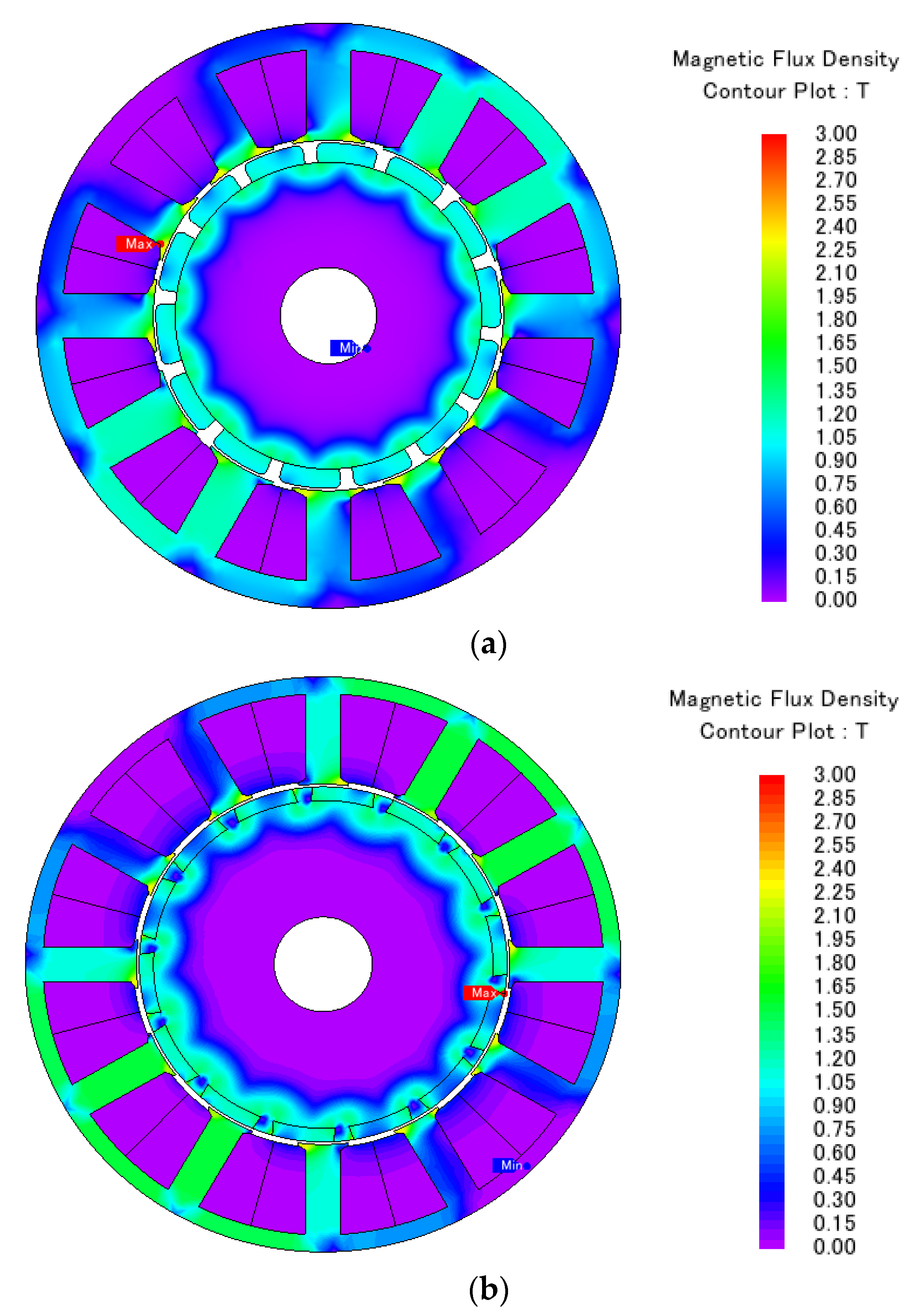
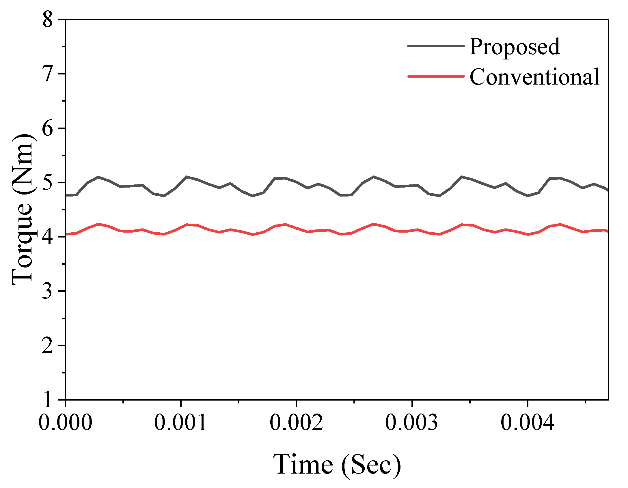
Finite Element Analysis Simulated Results

The cross-sections of the conventional and proposed topologies, no-load magnetic flux distribution, back EMF, torque vs. current angle and torque performance are shown in Figure 3, Figure 4, Figure 5, Figure 6, and Figure 7, respectively. These figures provide a comprehensive view of the proposed motor’s electromagnetic characteristics, capturing its magnetic saturation behavior, voltage response, and torque generation capabilities.
As illustrated in Figure 6, the motor exhibits a significant reluctance torque component due to the rotor’s geometric saliency. This contribution enhances the overall torque output, with a simulated peak torque of 4.88 Nm—representing a 20% increase relative to the baseline surface-mounted PMSM. In addition, the current density at peak torque is reduced to 10 A/mm2, compared to 15 A/mm2 in the reference design. The lower current loading is beneficial for thermal performance, allowing extended high-torque operation without exceeding material or insulation temperature limits. These results indicate that introducing rotor saliency through a surface-inset configuration, combined with appropriate material and dimensional optimization, can improve torque density and reduce thermal stress, supporting the requirements of high-demand eMTB applications. The peak torque performance was evaluated under a simulated current density of approximately 14.5 A/mm2 for the conventional design, yielding a maximum torque of around 4 Nm. In contrast, the proposed surface-inset PMSM design achieves a peak torque of 4.9 Nm at a reduced current density of 10 A/mm2, representing a 23% improvement in torque output with a 31% reduction in current density. This improvement is primarily due to the introduction of rotor saliency, which enables partial reluctance torque contribution, enhancing overall torque output without relying solely on magnet torque. The simulated results align well with performance values reported in publicly available datasheets for comparable motor configurations, supporting the viability of the proposed design for demanding e-bike applications.

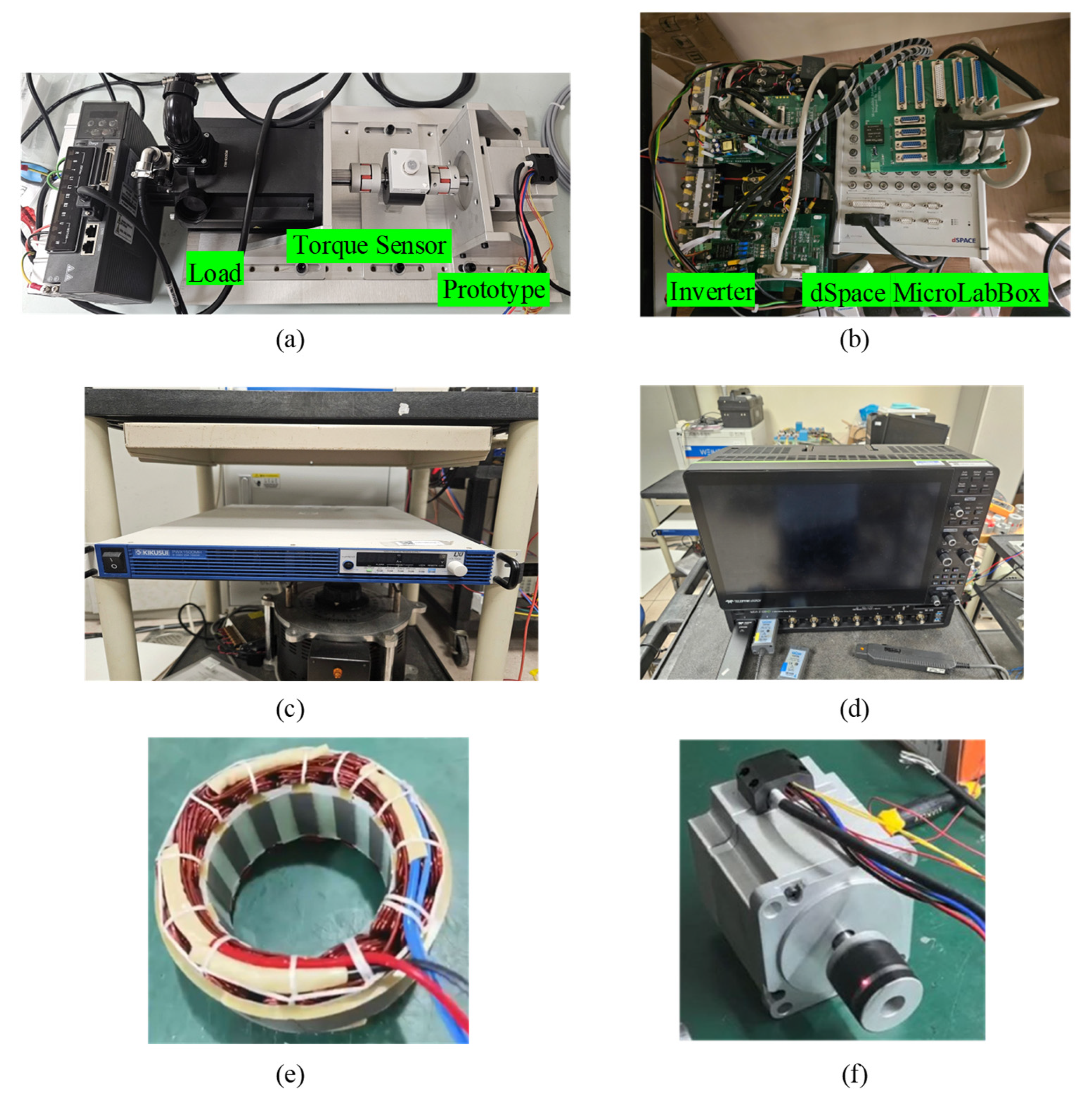
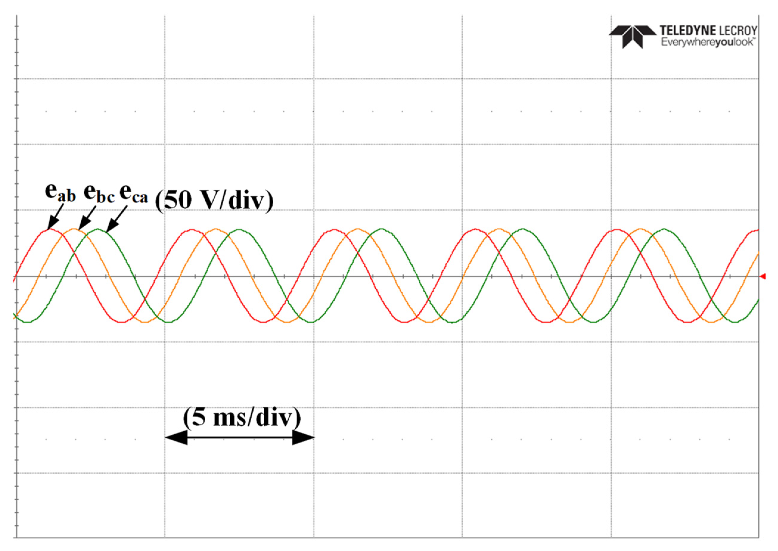
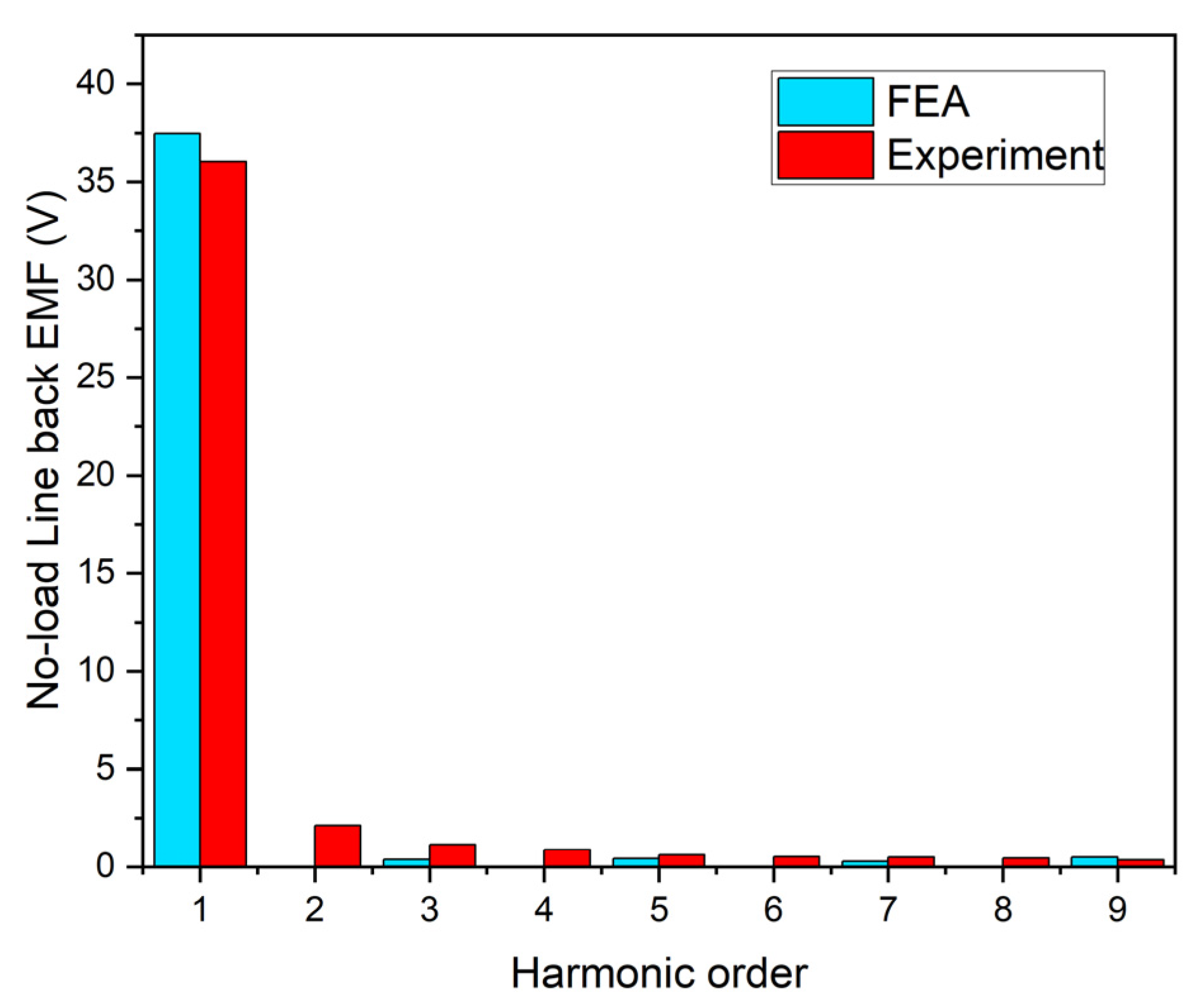
5. Experimental Results

The proposed motor is fabricated to validate the foregoing analysis and the FEA results, with the main design parameters listed in Table 2.
Figure 8a shows the prototype and on-load test bench. The control system consists of a three-phase voltage source inverter (VSI) and dSPACE MicroLabBox. The proposed prototype is connected to the load through an HBM torque transducer. The electric and torque signals are displayed in a high-performance oscilloscope LECROY-MDA 8108HD (Teledyne LeCroy, Chestnut Ridge, NY, USA). The experimental results confirm that the three-phase back-EMF waveforms exhibit symmetry and sinusoidal distribution, as illustrated in Figure 9. A comparative analysis of the harmonic spectra between the measured and finite element analysis (FEA)-simulated back-EMFs reveals strong agreement, with a minor deviation of 5% observed in the fundamental component in Figure 10. This discrepancy falls within acceptable limits and is primarily attributed to end effects and manufacturing tolerances inherent in the prototype assembly. The alignment between simulation and measurement underscores the validity of the adopted FEA methodology for predicting electromagnetic performance.
Furthermore, the on-load test is conducted with a phase current amplitude of 29.3 A to measure the peak torque performance of the motor. The prototype is operated at 500 r/min; the measured output torque and current waveforms are shown in Figure 11. The measured average torque is 4.62 Nm, which is 5% lower than the simulated results. The error is mainly attributed to several contributing factors. First, frictional losses from bearing drag and mechanical coupling were not explicitly modeled in the simulation. Second, material property discrepancies may exist between the idealized steel data (e.g., 50JN1300) used in the simulation and the actual batch-dependent characteristics of the laminations used in the prototype. Finally, the experimental test rig introduces real-world effects such as shaft misalignment, sensor resolution limits, and controller-induced ripple, all of which are absent in the idealized FEA environment. A summary of the performance is shown in the Table 3 below.

6. Conclusions

This study presents a design methodology for surface-mounted permanent magnet synchronous motors (SPMSMs) aimed at improving torque performance in electric mountain bike (eMTB) applications. A representative baseline motor, typical of those used in lightweight mid-drive systems, was analyzed to identify performance limitations related to torque density and current loading. Although the baseline design offers simplicity and ease of manufacturing, its reliance on magnetically excited torque limits peak output under high-load conditions, such as steep gradient climbs. To overcome this constraint, a surface-inset rotor topology was introduced. By incorporating geometric saliency, the proposed design enables partial utilization of reluctance torque while preserving rotor simplicity and manufacturability.
Finite element analysis (FEA) results indicate that the proposed surface-inset PMSM achieves a 20% increase in peak torque output (4.88 Nm) relative to the baseline surface-mounted design. This improvement directly supports the torque demands associated with off-road acceleration and steep incline traversal in eMTB applications. Furthermore, the required current density at peak torque is reduced by approximately 31% (from 14.5 A/mm2 to 10 A/mm2), contributing to lower thermal stress and enabling more consistent high-load operation. Experimental testing of the fabricated prototype demonstrated close agreement with simulation results, with minor deviations attributed to mechanical losses and fixture friction in the test bench. These findings highlight the effectiveness of incorporating rotor saliency in achieving higher torque density without significant design complexity. Nonetheless, the current required for peak torque remains substantial, limiting continuous operation without additional thermal mitigation. To address this, future work will investigate flux-focusing rotor geometries to further enhance saliency and reduce current requirements. In addition, dynamic testing under representative trail conditions and the implementation of improved cooling strategies will be necessary to assess long-term performance and durability. By addressing the limitations of conventional surface-mounted PMSMs in high-torque applications, this work establishes a scalable approach to motor design for eMTBs that balances electromagnetic performance, manufacturability, and thermal considerations. The proposed surface-inset topology demonstrates the feasibility of achieving higher torque density within existing packaging constraints, supporting improved rider experience in demanding terrain. More broadly, these design strategies contribute to the advancement of efficient, compact electric drivetrains for lightweight electric mobility platforms.

Author Contributions

Validation, H.W., S.Z. and K.Y.; Resources, S.Z.; Investigation, S.Z.; Writing—original draft, J.W.G.; Writing—review & editing, S.X.; Supervision, S.X. and C.H.T.L.; Funding acquisition, C.H.T.L. All authors have read and agreed to the published version of the manuscript.

Funding

The research of the project was supported by Specialized Asia Pacific Pte. Ltd., Singapore, under Grant No. 04IDS001538C140.

Data Availability Statement

The original contributions presented in the study are included in the article, further inquiries can be directed to the corresponding author.

Conflicts of Interest

The authors declare that this study received funding from Specialized Asia Pacific Pte. Ltd., Singapore. The funder had the following involvement with the study: The funder was involved in the study design, collection and analysis. The funder was not involved in the writing of this article or the decision to submit it for publication.

References

  1. Contò, C.; Bianchi, N. E-Bike Motor Drive: A Review of Configurations and Capabilities. Energies 2022, 16, 160. [Google Scholar] [CrossRef]
  2. Contò, C.; Bianchi, N. A Guideline for Selecting Motors for Electric Bikes Based on Magnetic Analysis and Measurements. IEEE Trans. Energy Convers. 2024, 39, 97–106. [Google Scholar] [CrossRef]
  3. Muetze, A.; Tan, Y.C. Modeling and Analysis of the Technical Performance of DC-Motor Electric Bicycle Drives Based on Bicycle Road Test Data. In Proceedings of the 2007 IEEE International Electric Machines & Drives Conference, Antalya, Turkey, 3–5 May 2007; Volume 2, pp. 1574–1581. [Google Scholar]
  4. E-Bike Lithium-ion Battery Market Size, Market Outlook, Trends & Forecast; Bikes and Motorcycles; V.M. Reports: Washington, DC, USA, February 2025; Available online: https://www.verifiedmarketreports.com/product/e-bike-lithium-ion-battery-market/ (accessed on 14 May 2025).
  5. Xie, S.; Yu, Y.; Yang, G.; He, Y.; Yan, Y.; Cai, S.; Yuan, X.; Han, B.S.; Hoang, C.C.; Lee, C.H.T. Comprehensive Comparison of Permanent Magnet Synchronous Machine and Vernier Machine. In Proceedings of the IECON 2023—49th Annual Conference of the IEEE Industrial Electronics Society, Singapore, 16–19 October 2023; IEEE: Piscataway, NJ, USA, 2023; pp. 1–6. [Google Scholar]
  6. Lee, C.H.T.; Hua, W.; Long, T.; Jiang, C.; Iyer, L.V. A Critical Review of Emerging Technologies for Electric and Hybrid Vehicles. IEEE Open J. Veh. Technol. 2021, 2, 471–485. [Google Scholar] [CrossRef]
  7. Cao, L.; Chau, K.T.; Lee, C.H.T.; Lam, W.-H. Design and Analysis of a New Parallel-Hybrid-Excited Machine With Harmonic-Shift Structure. IEEE Trans. Ind. Electron. 2020, 67, 1759–1770. [Google Scholar] [CrossRef]
  8. Gonzalez-Garcia, S.; Aguilar-Zamorate, I.S.; Galluzzi, R.; Zenerino, E.C.; Tonoli, A. Optimizing Mid-Drive Electric Motor Performance and Cost for Electric Bike Applications. In Proceedings of the 2024 International Conference on Electrical Machines (ICEM), Torino, Italy, 1–4 September 2024; pp. 1–7. [Google Scholar]
  9. Lin, J.; Schofield, N.; Emadi, A. External-Rotor 6-10 Switched Reluctance Motor for an Electric Bicycle. IEEE Trans. Transp. Electrif. 2015, 1, 348–356. [Google Scholar] [CrossRef]
  10. Chlebosz, W.; Ombach, G.; Junak, J. Comparison of permanent magnet brushless motor with outer and inner rotor used in e-bike. In Proceedings of the XIX International Conference on Electrical Machines—ICEM 2010, Rome, Italy, 6–8 September 2010; pp. 1–5. [Google Scholar]
  11. Zhu, J.; Yuan, X.; Eric Cheng, K.W.; Lee, C.H.T. Deep-investigated Flux Weakening Analysis of the Direct-drive Surface Permanent Magnet Vernier Motors for Traction Applications. In Proceedings of the 2022 IEEE 9th International Conference on Power Electronics Systems and Applications (PESA), Hong Kong, China, 20–22 September 2022; IEEE: Piscataway, NJ, USA; pp. 1–7. [Google Scholar]
  12. Turbo Levo—Specialized. Available online: https://www.specialized.com/us/en/shop/bikes/electric-bikes/electric-mountain-bikes/turbo-levo (accessed on 14 May 2025).
  13. Performance Line CX: The Sportiest Bosch Motor for eMTBs. Available online: https://www.bosch-ebike.com/en/products/performance-line-cx (accessed on 14 May 2025).
  14. EP8 DRIVE UNIT. Available online: https://bike.shimano.com/products/components/pdp.P-DU-EP801.html (accessed on 14 May 2025).
  15. Hunger, M. Yamaha PW-X3—In Our Big E-Mountainbike Motor Comparison Test. Available online: https://ebike-mtb.com/en/yamaha-pw-x3-review/ (accessed on 14 May 2025).
  16. Datasheet_Brose_DrivePeak3. Available online: https://www.brose-ebike.com/de-en/products/ (accessed on 19 June 2025).
  17. Bafang Home. Available online: https://www.bafang-e.com/en/products/motors/m-series/m510 (accessed on 14 May 2025).
  18. FAZUA RIDE 60. Available online: https://fazua.com/en/products/ride-60/ (accessed on 14 May 2025).
  19. The New TQ-HPR50 E-BIKE SYSTEM. Available online: https://www.tq-ebike.com/en/ (accessed on 14 May 2025).
  20. GX Ultimate Mountain. Available online: https://industry.panasonic.eu/products/devices/e-bike-systems/e-bike-motor-unit/gx-ultimate-mountain (accessed on 14 May 2025).
  21. Ecodrive Plus Battery E-Bike Battery 36V 48V Spare Battery Pack. Available online: https://www.falconpev.com.sg/collections/best-e-bike-e-scooter-for-singapore-ul2272-en15194/products/ecodrive-48v-10ah-detachable-battery (accessed on 30 May 2025).
  22. Infineon Technologies AG. REF_48V_270W_EBIKE|Compact Motor Inverter for E-Bikes and Micromobility—Infineon Technologies. Available online: https://www.infineon.com/cms/en/product/evaluation-boards/ref_48v_270w_ebike/ (accessed on 30 May 2025).
  23. 60V-72V 1500W-3000W 45A 3-Mode Sine Wave Ebike Controller with Colorful LCD Display (Regenerative only for 60/72V). Available online: https://hallomotor.com/products/60v-72v-1500w-3000w-45a-3-mode-sine-wave-ebike-controller-with-colorful-lcd-display-regenerative-only-for-60v-72v (accessed on 30 May 2025).
  24. Brose Significantly Extends the Lifespan of the S Mag. Available online: https://www.brose-ebike.com/de-en/presse/smag.html (accessed on 30 May 2025).
  25. Mark, S. E-Bike Tech Explained: Torque Sensor or Cadence Sensor? Cycling Electric. 2023. Available online: https://www.cyclingelectric.com/in-depth/e-bike-tech-explained-torque-sensor-or-cadence-sensor (accessed on 30 May 2025).
  26. TT-EBIKE Bicycle Crank Arm, 170mm Aluminium Alloy Crank Arm Set Bike Cr. Available online: https://www.tt-ebike.com/?srsltid=AfmBOoqTBIeebUIwuXEJ4iqh-SYRhnX85avFgbdGMm3St4ULxOjtjWiV (accessed on 30 May 2025).
  27. Faradonbeh, M.A.; Faradonbeh, V.Z.; Amiri, E. Design Modeling and Prototyping of a 55 Watts Surface Mounted PM Machine With High Torque and Low Torque Ripple for Cooling Fan Application. IEEE Access 2024, 12, 50244–50253. [Google Scholar] [CrossRef]
  28. El-Refaie, A.M.; Jahns, T.M.; Novotny, D.W. Analysis of Surface Permanent Magnet Machines With Fractional-Slot Concentrated Windings. IEEE Trans. Energy Convers. 2006, 21, 34–43. [Google Scholar] [CrossRef]
  29. Zhu, Z.Q.; Howe, D. Instantaneous magnetic field distribution in brushless permanent magnet DC motors. III. Effect of stator slotting. IEEE Trans. Magn. 1993, 29, 143–151. [Google Scholar] [CrossRef]
  30. Liu, X.; Chen, H.; Zhao, J.; Belahcen, A. Research on the Performances and Parameters of Interior PMSM Used for Electric Vehicles. IEEE Trans. Ind. Electron. 2016, 63, 3533–3545. [Google Scholar] [CrossRef]
  31. Yang, Y.; Castano, S.M.; Yang, R.; Kasprzak, M.; Bilgin, B.; Sathyan, A.; Dadkhah, H.; Emadi, A. Design and Comparison of Interior Permanent Magnet Motor Topologies for Traction Applications. IEEE Trans. Transp. Electrif. 2017, 3, 86–97. [Google Scholar] [CrossRef]
  32. Wang, J.; Yuan, X.; Atallah, K. Design Optimization of a Surface-Mounted Permanent-Magnet Motor With Concentrated Windings for Electric Vehicle Applications. IEEE Trans. Veh. Technol. 2013, 62, 1053–1064. [Google Scholar] [CrossRef]
  33. Gan, J.; Chau, K.T.; Chan, C.C.; Jiang, J.Z. A new surface-inset, permanent-magnet, brushless DC motor drive for electric vehicles. IEEE Trans. Magn. 2000, 36, 3810–3818. [Google Scholar] [CrossRef]
Figure 1. Block diagram of the e-bike system, consisting of Battery [21], Inverter [22], Controller [23], Motor [24], Torque & Cadence Sensor [25] and Pedal Crank [26].
Energies 18 03709 g001
Figure 2. Details of stator concentrated winding. (a) Double-layer winding coil. (b) Single-layer winding coil. (c) End turn configuration [28].
Energies 18 03709 g002
Figure 3. (a) Conventional SPMSM; (b) Proposed Surface Inset PMSM.
Energies 18 03709 g003
Figure 4. Magnetic flux distribution; (a) conventional prototype; (b) proposed prototype.
Energies 18 03709 g004
Figure 5. No-load back EMF; (a) conventional prototype; (b) proposed prototype.
Energies 18 03709 g005
Figure 6. Torque vs. Current Angle.
Energies 18 03709 g006
Figure 7. Torque performance.
Energies 18 03709 g007
Figure 8. (a) Proposed prototype; (b) test rig; (c) power supply; (d) LECROY-MDA 8108HD; (e) stator; (f) proposed prototype.
Energies 18 03709 g008
Figure 9. No-load line back EMF.
Energies 18 03709 g009
Figure 10. Harmonic spectra compared with FEA results.
Energies 18 03709 g010
Figure 11. Measured steady-state torque and current waveforms.
Energies 18 03709 g011
Table 1. Comparison of Motor Models.
BrandMotorTorque (Nm)Motor Weight (kg)
SpecializedSpecialized Turbo [12]902.98
BoschBosch Performance Line CX [13]852.9
ShimanoShimano EP8 [14]852.6
YamahaYamaha PW-X3 [15]852.75
BroseBrose Drive 3 [16]952.9
BafangBafang M510 [17]952.9
FazuaFazua Ride 60 [18]601.96
TQTQ-HPR50 [19]501.85
PanasonicPanasonic GX Ultimate [20]952.95
Table 2. Measured Parameters.
ParametersConventional PrototypeProposed
Number of stator slots12
Number of rotor pole pairs7
Gear ratio27.1
Stator outer diameter (mm)91
Stator inner diameter (mm)54.557
Stack length (mm)25
Winding factor0.933
Stator yoke thickness (mm)4.12.7
Stator teeth width (mm)75.4
Tooth tip (mm)37.2
Pole arc (degrees)2119.3
PM thickness (mm)32.18
Slot filling factor0.30.4
Current density A/mm214.510
PM materialN42UHN48
Steel type50JN1300
Table 3. Performance Comparison.
ParametersBenchmark MotorProposed Motor SimulationExperimental
Peak torque4 Nm4.9 Nm4.62 Nm
Torque density24.6 kNm/m330.14 kNm/m328.41 kNm/m3
Efficiency83%84%80%
Copper losses93 W85 W-
Torque/PM volume416 Nm/L673 Nm/L635 Nm/L
Peak power628 W770 W726 W
Rated speed (rpm)150015001500
Disclaimer/Publisher’s Note: The statements, opinions and data contained in all publications are solely those of the individual author(s) and contributor(s) and not of MDPI and/or the editor(s). MDPI and/or the editor(s) disclaim responsibility for any injury to people or property resulting from any ideas, methods, instructions or products referred to in the content.

