Article

Development and Performance Evaluation of Central Pipe for Middle-Deep Geothermal Heat Pump Systems

1
School of New Energy, Xi’an Shiyou University, Xi’an 710065, China
2
School of Mechanical Engineering, Xi’an Shiyou University, Xi’an 710065, China
3
Power China Northwest Engineering Corporation Limited, Xi’an 710065, China
*
Author to whom correspondence should be addressed.
Energies 2025, 18(14), 3713; https://doi.org/10.3390/en18143713
Submission received: 29 May 2025 / Revised: 26 June 2025 / Accepted: 3 July 2025 / Published: 14 July 2025
(This article belongs to the Special Issue Heat Transfer and Fluid Flows for Industry Applications)

Abstract

In this study, the optimal design of the central pipe in a middle-deep geothermal heat pump (MD-GHP) system is studied using the response surface method to improve the system’s coefficient of performance (COP) and operational reliability. Firstly, a model describing the energy transfer and conversion mechanisms of the MD-GHP system, incorporating unsteady heat transfer in the central pipe, is established and validated using field test data. Secondly, taking the inner diameter, wall thickness, and effective thermal conductivity of the central pipe as design variables, the effects of these parameters on the COP of a 2700 m deep MD-GHP system are analyzed and optimized via the response surface method. The resulting optimal parameters are as follows: an inner diameter of 88 mm, a wall thickness of 14 mm, and an effective thermal conductivity of 0.2 W/(m·K). Based on these results, a composite central pipe composed of high-density polyethylene (HDPE), silica aerogels, and glass fiber tape is designed and fabricated. The developed pipe achieves an effective thermal conductivity of 0.13 W/(m·K) and an axial tensile force of 29,000 N at 105 °C. Compared with conventional PE and vacuum-insulated pipes, the composite central pipe improves the COP by 11% and 7%, respectively. This study proposes an optimization-based design approach for central pipe configuration in MD-GHP systems and presents a new composite pipe with enhanced thermal insulation and mechanical performance.

1. Introduction

Geothermal energy primarily originates from the heat accumulated in the Earth’s core during its formation, as well as the heat released from the decay of radioactive elements within the Earth. This energy is predominantly transferred to the surface via convection and conduction, which make it accessible for human utilization. Compared to other renewable energy sources such as solar and wind energy, geothermal energy exhibits a lower energy grade but superior stability and sustainability, which makes its use more advantageous in district heating and domestic hot water supply [1,2].
Currently, the development and utilization of geothermal resources primarily adopt four methodologies: groundwater circulation, underground heat exchangers, ultra-long gravity heat pipes, and enhanced geothermal systems (EGSs). In the groundwater circulation method, a well is drilled to the groundwater layer, and groundwater is pumped to the surface to release heat. Water is then reinjected into the formation, with the well depths ranging from 120 m to 3000 m [3]. The underground heat exchanger method is divided into two categories: shallow direct buried heat exchanger systems, in which geothermal energy is extracted from shallow formations by drilling holes that are approximately 150 mm in diameter and 130~200 m in depth, into which a single or double U-shaped polyethylene (PE) pipe is inserted to form an underground heat exchanger that uses water or antifreeze as the circulating fluid [4]; and medium-deep geothermal heat pump (MD-GHP) systems, which extract geothermal energy from medium-deep rock formations (200~3500 m). This method requires drilling holes with diameters of 215~444 mm, inserting casings with inner diameters of 121~320 mm, and cementing. A central pipe is placed inside the casing to establish a closed circulation loop, wherein water extracts geothermal energy from the surrounding formation [5,6]. The wellbore structure of the ultra-long gravity heat pipe method is analogous to that of the MD-GHP system. Following well completion, the casing’s base is sealed, and an organic working fluid is injected to create a gravity heat pipe that extracts geothermal energy from the deep formation [7]. The EGS method is primarily designed for extracting geothermal energy from deep underground rocks (over 3500 m) by drilling an injection well into high-temperature formations, which is followed by perforation and fracturing after the casing is cemented to create numerous cracks in the formation that connect with a production well. Circulating water flows into the injection wells and extracts heat through these fractures [8].
Among these methodologies, the MD-GHP system has become a significant approach for geothermal energy extraction and utilization, due to its advantages of being low cost, creating minimal pollution, and being high efficiency, particularly in northern China’s winter heating sector [9]. Figure 1 illustrates a typical schematic diagram of an MD-GHP system, wherein the underground heat exchanger comprises two concentric pipes: the outer pipe serves as the casing, while the inner pipe functions as the central pipe. The circulating water is injected into the wellbore through the annulus, and extracts heat from the formation during its downward flow. The fluid returns to the surface via the central pipe after reaching the bottom of the well, releasing heat in the heat pump evaporator before re-entering the wellbore for circulation. The extracted geothermal energy, characterized as medium-low-grade thermal energy, is particularly suitable for district and greenhouse heating.
In MD-GHP systems, the central pipe’s primary function is to separate the circulating fluid within it from the fluid in the annulus, while simultaneously reducing the heat dissipation of the fluid inside the central pipe. Furthermore, the central pipe must not only meet the lifting requirements of the lower counterweight pipe and sieve pipe during construction but must also remain intact during prolonged service in the high-temperature section at the well’s base. Additionally, the dimensions and surface roughness of the central pipe significantly influence the flow resistance of the circulating fluid, with the flow resistance directly impacting the circulating pump’s power consumption. Therefore, the central pipe must fulfill requirements for robust mechanical properties, effective thermal insulation performance, low friction of the circulating fluid, and cost-effective production and installation. As a critical component of the MD-GHP system, the central pipe fundamentally determines the system’s technical feasibility and economic viability.
Currently, the central pipes employed in MD-GHP systems can be classified into single-layer and double-layer structures based on their design configuration, and can also be categorized as metallic or polymer-based materials from a material perspective [10]. The earliest documented MD-GHP system was established in Poland in 1996 utilizing the reconstruction of a 4098 m abandoned oil well, in which an ordinary single-layer steel oil pipe served as the central pipe. The effective depth of this central pipe was 2870 m, and it was observed that, due to the inadequate thermal insulation performance of the single-layer metal pipe, its thermal extraction capacity was limited to approximately 135 kW [11]. Therefore, some researchers have initiated efforts to enhance the thermal insulation of these systems by applying glass fiber, polyurethane foam, nano-aerogel layers, and other insulation materials to the exterior of single-layer oil pipes. For example, in the North China Oilfield, a silica aerogel layer was added to an oil pipe to raise the oil output temperature at the wellhead, which resulted in a 14.8 °C increase compared to conventional single-layer pipes [12]. Mohammad Afra et al. [13] sprayed silica-based nano coating onto an oil pipe, which formed a thermal insulation layer with a thickness of 5 mm, effectively reducing the heat loss up to 33%. However, the low strength of the insulation layer in the central pipe renders it susceptible to damage during installation and operation, which results in diminished thermal insulation performance and potential blockages. Therefore, certain oilfield enterprises have adopted double-layer vacuum-insulated pipes as central pipes in MD-GHP systems; these pipes are composed of double-layer steel pipes with a vacuum insulating layer in the annular gap between the inner and outer pipes. These pipes exhibit an effective thermal conductivity of approximately 0.10–0.12 W/(m·K) [14]. Dijkshoorn et al. [15] installed a vacuum-insulated central pipe in a geothermal well with a depth of 2500 m in Aachen for geothermal energy extraction, achieving favorable thermal extraction results. When the circulating rate was 10 m3/h, the temperature differential between the inlet and outlet water exceeded 30 °C. Li and Yang et al. [16] drilled a 2980 m geothermal well in Xi’an’s Xihua community, inserting an A-type vacuum-insulated oil pipe with an inner diameter of 76 mm and an outer diameter of 114.3 mm, and achieving a temperature difference of 15 °C between the inlet and outlet water at a circulating rate of 21 m3/h. The vacuum-insulated oil pipe’s superior thermal insulation performance and mechanical properties yielded a better thermal extraction capacity and reliability compared to other central pipe types under similar operational conditions. However, vacuum-insulated oil pipes face two significant challenges: a relatively high cost ranging from RMB 480 to 520 per meter and considerable flow resistance, which is attributable to their substantial radial dimensions and surface roughness.
At the same time, with the development of polymer materials, many MD-GHP systems utilize polymer plastic pipes as the central conduit, as these pipes exhibit favorable thermal insulation properties and low costs. For example, Si-ji-chun Geothermal Energy Co., Ltd. [17,18] has employed PE pipes as the central conduit in over 10 MD-GHP systems in the Guanzhong region of Shaanxi Province. The wellbore depth of these MD-GHP systems ranges from 2000 to 2500 m, with the inner diameter, outer diameter, and thermal conductivity of the central pipe being 90 mm, 110 mm, and 0.39 W/(m·K), respectively. The average heat extraction power of geothermal wells per unit depth is approximately 144 W/m. However, as the depth of the geothermal well and the temperature of the bottom hole increase, the inadequate mechanical properties of PE materials under high-temperature conditions become pronounced. Therefore, some researchers have attempted to incorporate a layer of polyester tape within PE pipes to enhance their high-temperature mechanical properties [19]. Meanwhile, in certain deep geothermal wells characterized by significant geothermal gradients, single-layer polypropylene (PP) pipes are utilized as the central conduit. The thermal conductivity of PP material is approximately 0.25 W/(m·K), and its tensile strength is about 15% greater than that of PE at equivalent temperatures [20]. However, due to the limited plasticity and toughness of PP pipes, they are susceptible to damage during installation and operation, which has resulted in their infrequent usage in MD-GHP systems.
In summary, the central pipe serves as a critical component that affects the thermal extraction power and the coefficients of performance (COPs) of MD-GHP systems. Present research has revealed issues such as the inadequate mechanical properties and insufficient thermal insulation capacity of PE pipes at elevated temperatures, their high costs, and the significant flow resistance of vacuum-insulated central pipes. However, fundamental investigations into the size, physical properties, and comprehensive performance of the central pipe are lacking, and no optimal design methods for the central pipe of the MD-GHP system have been established. This paper proposes a new optimization-based design approach for central pipe configuration in MD-GHP systems and develops a novel composite pipe with enhanced thermal insulation and mechanical performance.
This study constructs an energy transfer and conversion mechanism model for the MD-GHP system, incorporating unsteady heat transfer within the central pipe. Furthermore, the response surface optimization method is employed to assess the optimal size and effective thermal conductivity of the central pipe. Based on these, a composite central pipe composed of high-density polyethylene (HDPE), silica aerogels, and glass fiber tape is developed, with its effective thermal insulation capabilities and mechanical properties being analyzed through experimental and simulation methods. Meanwhile, the composite central pipe can achieve a single segment length of 500 m, which facilitates its transportation and installation, and thereby demonstrates promising application prospects in MD-GHP systems.

2. Methodology

2.1. Mathematical Models

To establish a quantitative relationship between central pipe parameters and the COPs of the MD-GHP system, energy balance equations for the central pipe, wellbore/formation, and circulating fluid are constructed, together with thermodynamic cycle models for the heat pump. For the central pipe and wellbore/formation, the temperature gradient along the circumferential direction is disregarded. The radial and circumferential temperature gradients of the circulating fluid are also neglected.

2.1.1. Heat Transfer and Flow Models of Circulating Fluid

The energy balance equation for circulating fluid can be presented as [21] follows:
ρ F luid C p F luid T F luid τ + ρ F luid C p F luid v T F luid Z = S p v α T T F l u i d
where TFluid is the fluid temperature; v is the velocity of the circulating fluid; ρ and Cp are the fluid density and specific heat capacity, respectively. Spv is the convective heat transfer area within the unit volume; α is the heat convection coefficient; T is the temperature of the pipe surface. Z is the depth of the wellbore; τ is the transient time.
In the annular, the fluid is in contact with the inner surface of the casing and the outer surface of the central pipe at the same time; thus, S p v α T T F l u i d can be rewritten as follows:
S p v α T T F l u i d = 2 r to r ci 2 r to 2 α 2 T 2 j T F luid j + 2 r ci r ci 2 r to 2 α 3 T 3 j T F luid j
where rto is the inside radius of the annular; rci is the outside radius of the annular; T2(j) is the outer surface temperature of the central pipe; T3(j) is the inner surface temperature of the casing. α2 and α3 are the convective heat transfer coefficient on the outside of the central pipe and the inside of the casing, respectively.
The fluid in the central pipe is in contact with the inner surface of the central pipe, and it can be calculated as follows:
S p v α T T F l u i d = 2 r ti α 1 T 1 j T F luid j
where rti is the central pipe’s internal radius; T1(j) is the central pipe’s inner surface temperature; α1 is the convective heat transfer coefficient on the inner surface of the central pipe.
One-dimensional flow models of the circulating fluid in the axial direction can be presented as follows [9]:
d P d Z = ± ρ Fluid g sin θ f t p ρ Fluid v 2 2 d e 1 ρ Fluid v 2 / P
In the above formula, the positive sign is for fluid in the annular and the minus sign is for fluid in the central pipe; de denotes the hydraulic diameter of the flowing space; ftp is the friction factor and calculated by William’s equation:
f t p = 13.16 g d e 0.13 C W 1.852 w t / ρ Fluid 0.148
where Cw is the roughness of the wellbore; wt is the circulating rate.
The pumping power required for a circulation pump to compensate for pressure loss can be calculated by the following equation [9]:
W pump = w t Δ P well + Δ P heat   pump ρ Fluid η
where ΔPwell is the pressure loss of the circulating fluid in geothermal wells, ΔPheat pump represents the pressure loss in the heat pump; η is the mechanical efficiency.

2.1.2. Heat Transfer Models for Central Pipe, Wellbore/Formation

The energy balance equations for the central pipe and wellbore/formation were established as follows [22]:
ρ C P T τ = Z λ T Z + 1 r r r λ T r
where ρ, Cp, and λ are the density, specific heat capacity, and thermal conductivity of the central pipe or wellbore/formation, respectively. r is the radial distance.
For the central pipe, heat transfer from the inner and outer sides is considered as the third boundary conditions, with convection heat transfer coefficients denoted as α1 and α2. For the wellbore/formation, the inner side of the casing is treated as the convective heat transfer boundary condition with α3. The outer side of the formation (re = 20 m) is treated as the fixed-wall temperature condition, with the boundary temperature corresponding to the initial formation temperature at the relevant depth.

2.1.3. Thermodynamic Cycle Models for Heat Pump

The heat pump system is a typical single-stage vapor compression refrigeration cycle, utilizing R134a as the refrigerant. The heat load of the condenser is given by the following equation [23]:
Q C = L hp h 2 h 3 = η C Q heating   load
h 2 = h 2 s h 1 / η 1 + h 1
where Lhp is the flow rate of refrigerant; h1 and h2 are the enthalpy value of the refrigerant before and after compression; h2s is the enthalpy value of the refrigerant after isentropic compression; ηC is the heat transfer efficiency of the condenser; η1 represents the isentropic efficiency. Qheatingload is the heating load of the system, which can be calculated by:
Q heating   load = L h C p T s T b
where Lh is the flow rate of heating water; Ts and Tb are the supply water temperature and back water temperature in the heating system. The power consumption of the compressor can be calculated as follows:
W = L hp h 2 h 1 / η 2
The heat load of the evaporator is determined as the difference between the heat load of the condenser and the power consumption of the compressor:
The heat absorbed by the evaporator can be described as follows:
Q E = Q C W = η E w C p T out T in
In this study, the coefficient of performance of the MD-GHP system can be calculated by the following equation:
C O P s = Q heating   load W + W pump

2.2. Solution of the Models

The variations in the COPs, temperature, and pressure in the MD-GHP system can be calculated as shown in Figure 2. (1) Assume the wellbore is filled with the circulating water, and that the initial temperature of the wellbore and water is the same as that of the surrounding formation. Input the circulating rate and the inlet temperature Tin. (2) Calculate the boundary conditions with Equations (2) and (3). (3) The temperature distributions of the central pipe, wellbore, and formation are calculated using Equation (7). (4) The temperature and pressure distributions of the circulating fluid are computed using Equations (1) and (4). (5) Compare the fluid temperature difference between steps 4 and 1, if the difference is bigger than the required accuracy, then replace the previous fluid temperature in step 1 with the newly calculated temperature in step 4, then recalculate the fluid temperature using steps 2–5, or else go on to step 6. (6) The inlet temperature and COPs are calculated using Equations (8)–(13). Then replace the previous Tin in step 1 with the newly calculated Tin. (7) Repeat steps 2–6 until the calculating time is reached. These models were solved using the C# programming language.

2.3. Validation of the Models

Validation data for the established models were obtained from a simulated heating experiment using the MD-GHP system in Xianyang, China. The geothermal well depth is 2500 m, and the effective circulation depth is 2460 m. The measured geothermal gradient is 3.5 °C/100 m. The heat released by the heat pump condenser is dissipated through a water-cooling tower to simulate the actual heating process. The schematic of the test system is shown in Figure 3. During the field tests, “chuanyi CYW11” temperature sensors (range: 0–300 °C) with a precision of 0.1 °C were used for detecting the inlet and outlet temperature of the geothermal well and cooling tower. Electromagnetic flow meters (Guanghua LDY-S, range: 0–50 m3/h) with a precision of 0.5% were equipped on both the geothermal well side and the cooling tower side. The measurement uncertainty of the electric power meter is 0.87%. A TPK-8000 model PID-controlled auxiliary system kept the inlet temperature of the geothermal well within ±0.3 °C of the setpoints. This strict control ensured accurate measurements, good experimental stability, and repeatability. For more details about the test procedure, please refer to [24].
Figure 4 illustrates the variation in the inlet water temperature, circulating rate, and heat load of the water-cooling tower during the experiment, which were measured and utilized as input data for the established models. A comparison between the calculated and measured values of the outlet temperature, pressure loss, and power consumption of the heat pump is presented in Figure 5.
As depicted in Figure 5a, the calculated outlet temperature demonstrates a strong correlation with the experimental measurements, accurately reflecting the unsteady-state variations in the outlet fluid temperature. It was found that the maximum difference between the experimental value and the calculated value was −9.3 °C, the minimum was 4.5 °C, and the difference was relatively large at the beginning of the experiment. Overall, the relative error of temperature prediction is within ±13%. In terms of pressure loss for circulation water in the geothermal well, the calculated values align well with the experimental measurements; however, discrepancies arise during rapid pressure transients (especially from 1200 min to 1400 min), likely due to the hysteretic behavior of the pressure sensor, and the maximum error during this period reached −0.21 MPa. In addition, the corresponding error was generally between −0.08~0.09 MPa, and the relative error generally remained within ±15%, as illustrated in Figure 5b. Throughout the experimental process, the calculated power consumption of the heat pump slightly exceeded the measured values, yet the overall trend remained consistent with the experimental data, as shown in Figure 5c. Except for abrupt operational conditions (around 0 min and 3000 min), the maximum difference between the experimental value and the calculated value was −8.1 kW, the minimum was 2.5 kW, and the relative error confined to ±12%.

3. Results and Discussion

3.1. Optimization of Central Pipe Based on Response Surface Method

3.1.1. Work Condition and Orthogonal Experiments

As illustrated in Figure 1, the dimensions of the central pipe determine the flow cross-sectional area for the circulating fluid, and thereby affect the pressure loss and power consumption of the circulation pump. Additionally, as the sole barrier against heat dissipation from the central pipe fluid to the annular fluid, the thermal conductivity of the central pipe directly influences the outlet temperature of the circulating fluid, which subsequently governs the overall operational efficiency of the system. Therefore, optimizing the central pipe’s size and effective thermal conductivity under specified working conditions represents a critical step for the MD-GHP system.
This study employs a newly constructed MD-GHP system in Chang’an, Xi’an, as a case study. The corresponding wellbore structure and formation parameters of the system are presented in Table 1, with fiber optic cables being installed on the exterior of the casing to measure the formation temperature. A heating period of four months is considered, during which the heating load and heating water temperature remain constant; the average COPs over this period serve as the evaluation metric.
In this section, it is assumed that the central pipe is a homogeneous medium with constant material properties. The inner diameter (dti), wall thickness (δt), and effective thermal conductivity (λt) of the central pipe are selected as variables for optimization. Utilizing COPs as the target metric, an orthogonal experimental design comprising three factors and six levels (as summarized in Table 2) is established.
Utilizing the model established in Section 2, the COPs of the corresponding MD-GHP system under various orthogonal experimental conditions were calculated and compiled in Table 2.

3.1.2. Optimization of Central Pipe Base on Response Surface Method

Using the data from Table 2, a response surface model (RSM) is developed within the response surface module of ANSYS2023 software, with the neural network being selected as the response surface type. The multi-objective genetic algorithm (MOGA) method is utilized for optimization analysis. Figure 6 illustrates the optimal inner diameter and thickness of the central pipe under varying effective thermal conductivities, with the maximization of the system COPs serving as the optimization criterion.
Figure 6 demonstrates that the dimensions of the optimal central pipe, when optimized under different thermal conductivities, vary significantly. As the thermal conductivity increases, the inner diameter decreases while the thickness increases. Using 1 W/(m·K) as a threshold for effective thermal conductivity, the optimal dimensions can be distinctly categorized into two regions: For a λt within 0.01~1 W/(m·K), the optimal inner diameter and thickness are approximately 88 mm and 14 mm, respectively. For a λt within 1~2 W/(m·K), the optimal dimensions shift to approximately 73 mm and 17.5 mm.
This variation arises because, at a low effective thermal conductivity, increases in the inner diameter and thickness of the central pipe have minimal effect on heat transfer between the fluid inside the central pipe and the annular fluid but exert a greater impact on the friction in the circulating fluid. Therefore, the optimal inner diameter of the central pipe is relatively large, and the optimal thickness is smaller, with the effect of the central pipe’s size on the circulation pressure loss being predominant. Conversely, when the λt is high, increases in the inner diameter significantly enhance the heat transfer area between the fluid inside the central pipe and the annular fluid, which results in a rapid increase in heat dissipation from the fluid within the central pipe.
Moreover, it is observed that, when the λt exceeds 1 W/(m·K), the system COPs are considerably lower than those for a λt below 1 W/(m·K). Given that the effective thermal conductivities of central pipe materials such as PE, PP, and vacuum-insulated central pipes are substantially lower than 1 W/(m·K), it can be concluded that, under normal operating conditions, the optimal inner diameter of the central pipe is approximately 88 mm and the optimal thickness is approximately 14 mm. To determine the optimal effective thermal conductivity of the central pipe, the variation in the COPs with λt when the inner diameter and thickness of the central pipe are 88 mm and 14 mm is calculated using the models in Section 2, as depicted in Figure 7.
As observed in Figure 7, as the effective thermal conductivity of the central pipe decreases, the COPs of the system initially increase rapidly and subsequently stabilize when the conductivity falls below 0.2 W/(m·K). When the thermal conductivity of the central pipe decreases from 0.2 W/(m·K) to 0.02 W/(m·K), the corresponding COPs increase by approximately 3%, while the costs associated with the central pipe escalate exponentially. Therefore, it can be inferred that, when the thermal conductivity of the central pipe approaches 0.2 W/(m·K), the system can achieve a balance between technical performance and economic feasibility.

3.2. Development a Novel Composite Central Pipe

As discussed in Section 3.1, the optimal inner diameter, wall thickness, and overall thermal conductivity of the central pipe for typical MD-GHP systems are approximately 88 mm, 14 mm, and 0.2 W/(m·K), respectively. Based on these parameters, a novel composite central pipe composed of HDPE, silica aerogels, and glass fiber tape was designed and manufactured with considerations being made for production costs, the downhole mechanical performance, and installation requirements. The structure is illustrated in Figure 8. The inner pipe consists of a 6 mm thick HDPE layer. Two layers of GE6530 glass fiber tape, each measuring 0.3 mm in thickness and wound at angles of +45° and −45°, respectively, are helically wrapped around the inner pipe. The glass fiber tape is produced through the melt impregnation of unidirectional continuous glass fibers with HDPE, with a glass fiber mass fraction of 65%. Surrounding the glass fiber layers is a 2.4 mm thick UG450 silica aerogel insulation layer, and the outer layer comprises a 5 mm thick HDPE layer. The entire central pipe is fabricated via hot-melt extrusion molding, with a total length of 500 m.

3.2.1. Insulation Performance of the Composite Central Pipe

To evaluate the thermal insulation capability of the composite pipe, the thermal conductivities of HDPE, silica aerogel, and glass fiber tape were tested at temperatures ranging from approximately 20 to 100 °C, in accordance with the national standard [25]. The test data are presented in Figure 9a. As depicted in Figure 9a, with an increasing temperature, the thermal conductivity of glass fiber tape shows a significant increase, while the thermal conductivity of HDPE exhibits a slight decrease, and the thermal conductivity of silica aerogel remains relatively stable. Meanwhile, the effective thermal conductivity of the composite pipe at varying temperatures was tested following the national standard [26], with the results being displayed in Figure 9b. Figure 9b illustrates that, as the temperature rises, the effective thermal conductivity experiences a slight increase. And the effective thermal conductivity of the composite central pipe is notably lower than that of HDPE, remaining approximately at 0.13 W/(m·K). This is due to the low thermal conductivity of the silica aerogels, which forms a high local thermal resistance, reducing the overall effective thermal conductivity of the composite pipe. Moreover, since the silica aerogels have good thermal stability, the effective thermal conductivity of the composite tube basically does not change with the temperature.
The effective thermal conductivity of the composite central pipe evaluated in this section is lower than the optimal value of 0.2 W/(m·K) and exhibits limited temperature dependence, which indicates that it fully satisfies the thermal insulation requirements of MD-GHP systems.

3.2.2. Tensile Performance of the Composite Central Pipe

Given that the density of polymer materials, such as PE and PP, is lower than that of water, the composite central pipe typically requires a section of metal pipe at its base to serve as a counterweight. Therefore, the composite central pipe must demonstrate sufficient tensile strength under high-temperature downhole conditions. In this study, a high-temperature tensile test for the composite central pipe was conducted in accordance with the national standard [27] using a 30-ton horizontal tensile testing machine. A 1.5 m long test segment was connected at both ends via custom clamping collars. The pipe was subjected to heat in dual upper and lower heating chambers, with a temperature of 105 °C being targeted, and with a heating rate of 2 °C/min and a thermal soaking period of 4 h, as illustrated in Figure 10a. The measured tension–displacement curve during the tensile process is shown in Figure 10b.
Based on Figure 10b, the composite central pipe exhibits notable secondary plasticity characteristics during the tensile test at 105 °C. In the plastic deformation phase, when the tensile force is below 18,000 N, the curve displays a linear segment, indicating the true plastic deformation of the composite pipe. In the pseudo-elastic phase, between 18,000 N and 29,000 N, a secondary linear segment emerges with a lower slope. This phenomenon arises as the glass fiber layer begins to sustain damage and undergo plastic deformation, while the other material layers remain in the elastic deformation state. When the tensile force exceeds 29,000 N, there is a significant abrupt change in the tension curve, which is due to the large deformation causing delamination between the glass fiber layer and the HDPE layer, and results in complete failure of the composite central pipe. The results indicate that the composite central pipe can withstand a maximum tensile force of 29,000 N at 105 °C, satisfying the counterweight requirements for geothermal wells with depths less than 3000 m.

3.3. Comparative Analysis with Existing Central Pipes

In this section, the operational performance of the aforementioned composite central pipe is compared with existing PE central pipes and vacuum-insulated central pipes, which are widely utilized in China. The corresponding working conditions of the MD-GHP system used for this analysis are consistent with those described in Section 3.1. The inner diameter and outer diameter of the composite central pipe are 88 mm and 116 mm, respectively, and the pipe has an effective thermal conductivity of 0.13 W/(m·K); the inner diameter and outer diameter of the PE central pipe are 90 mm and 110 mm, respectively, and the pipe has a thermal conductivity of 0.39 W/(m·K); the inner diameter and outer diameter of the vacuum-insulated central pipe are 76 mm and 114 mm, respectively, and the pipe has an effective thermal conductivity of 0.109 W/(m·K).
Figure 11 illustrates the variation in the calculated COPs and pressure loss in the well with the same circulating rates for different central pipes. For all three central pipes, as the circulating rate increases, the system COPs initially rise to a peak and subsequently decline, with each pipe demonstrating a unique optimal circulating rate that maximizes the resulting COPs. This phenomenon primarily occurs because increasing the circulating rate enhances the thermal extraction power of the geothermal well, and thereby reduces the heat pump’s power consumption. However, the pressure loss of the circulating fluid simultaneously rises, significantly increasing the energy consumption of the circulating pump (see Figure 11b). The interplay between these two opposing effects ultimately results in the observed trend of an initial increase followed by a decrease in COPs.
The optimal circulating rates of the composite central pipe, PE central pipe, and insulated tubing were 24.3 m3/h, 29.0 m3/h, and 22.5 m3/h, and the corresponding COPs were 5.14, 4.65, and 4.87, respectively. For the PE central pipe, due to its larger diameter, the pressure loss of the circulating fluid at the same rate is significantly lower than that of the other two types, which results in a reduced proportion of circulating pump power consumption in the total power consumption of the system. Therefore, the corresponding optimal circulating rate is higher.
Moreover, as shown in Figure 11a, when the circulating rate is below 10 m3/h, the composite pipe exhibits marginally lower COPs than the vacuum-insulated pipe due to its slightly higher effective thermal conductivity, which amplifies conductive heat losses under low-flow conditions. Within the range of 10~40 m3/h, the composite pipe achieves higher COPs than the other two types. This advantage is attributed to its optimized thermal resistance and flow resistance, which minimize the thermal dissipation while maintaining moderate pressure loss. Beyond 40 m3/h, the COPs for the composite pipe become inferior to those of the PE pipe due to its inherently higher flow resistance.
Figure 12 presents the variation in the calculated COPs and pressure loss with the well depth for the three types of central pipes, with the water circulating rate set to the previously determined optimal value. As illustrated in Figure 12a, with an increasing well depth, the COPs of the system exhibit exponential growth. This phenomenon is primarily due to the simultaneous increase in the temperature difference and heat transfer area between the circulating fluid and the formation at greater well depths, which leads to an exponential increase in the outlet temperature of the circulating fluid under a constant heating load, which, in turn, ultimately produces the trend depicted in Figure 12a. Furthermore, as demonstrated in Figure 12a, the composite central pipe exhibits superior COPs compared to the other two pipe types across varying well depths, with the corresponding pressure loss being comparable to that of the PE central pipe (see Figure 12b). Notably, this performance advantage becomes increasingly pronounced at greater wellbore depths.
In summary, the composite central pipe developed in this study demonstrates a significantly improved operational efficiency compared to existing central pipe types, and its tensile performance at downhole temperatures is also commendable. Additionally, its production cost is below RMB 140 per meter, and the length of a single pipe can reach 500 m, which facilitates convenient transportation and installation. The composite central pipe offers excellent economic and technical performance, particularly for MD-GHP systems with geothermal well depths less than 3000 m.

4. Conclusions

The optimal design of the central pipe for a MD-GHP system was conducted based on unsteady numerical simulation, response surface optimization, and experimental methods. A novel composite central pipe was developed and effectively evaluated, which led to the following conclusions:
(1)
The transient heat transfer model, flow model, and heat pump thermodynamic cycle model developed in this study for the MD-GHP system demonstrated substantial capability to accurately characterize the energy transfer and conversion dynamics within the system, providing a robust framework for central pipe optimization design research;
(2)
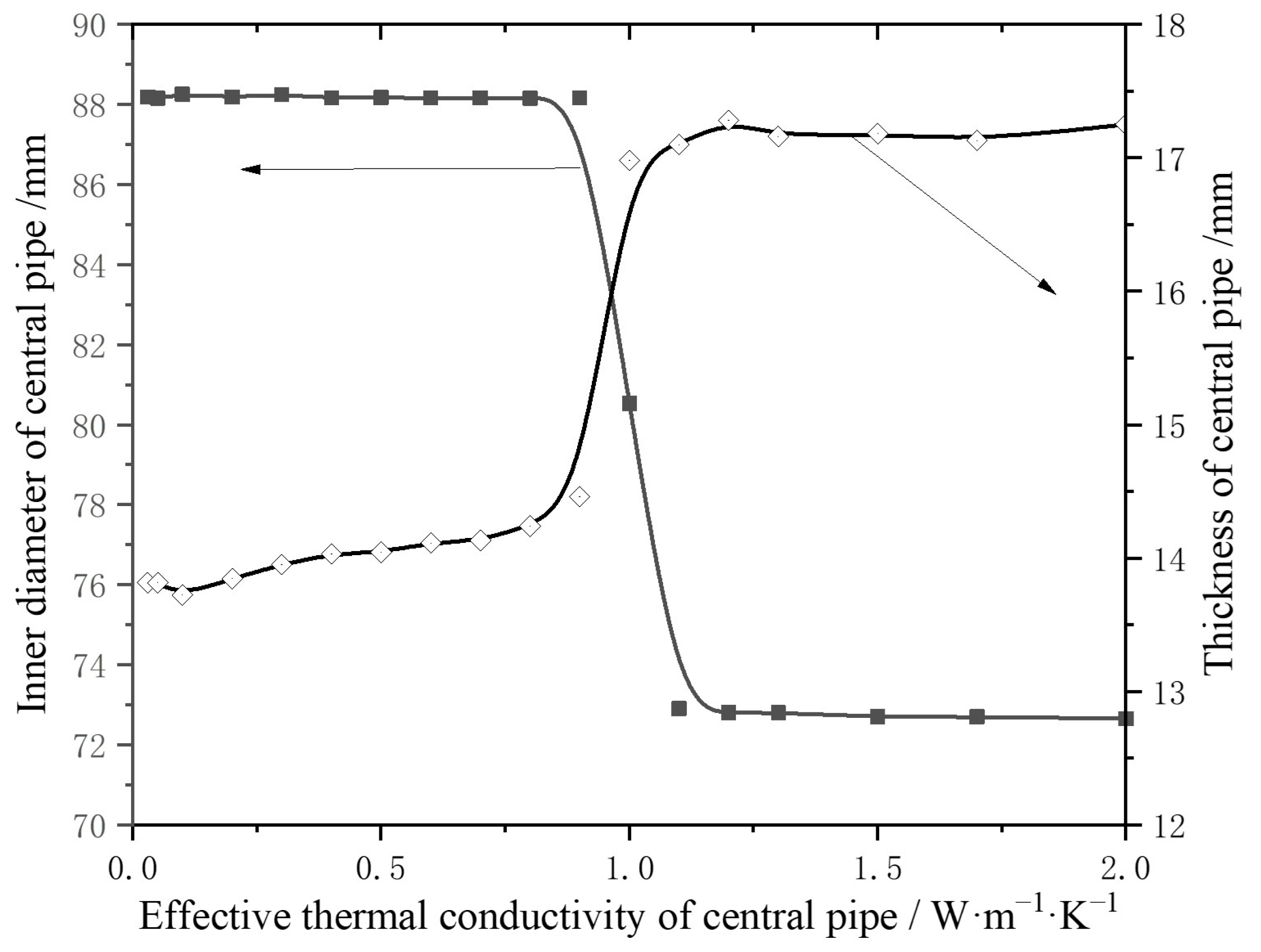
The influence of various central pipe parameters on the COPs of an MD-GHP system with a well depth of 2700 m was analyzed and optimized using the response surface optimization method, which resulted in the identification of optimal central pipe parameters: an inner diameter of 88 mm, a thickness of 14 mm, and an effective thermal conductivity of 0.2 W/(m·K);
(3)
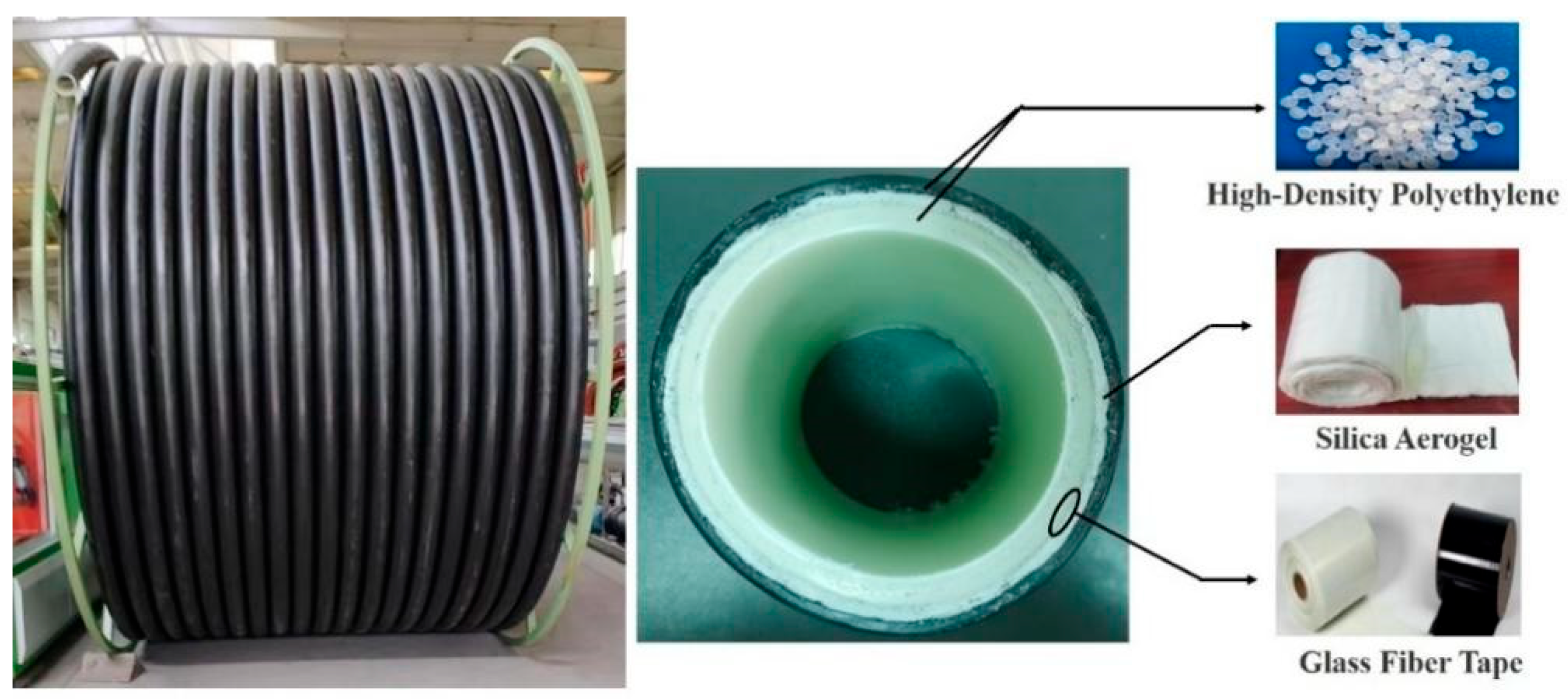
A novel composite central pipe, composed of HDPE, silica aerogels, and glass fiber tape, was designed and manufactured, with an effective thermal conductivity of 0.13 W/(m·K) and an axial tensile force of 29,000 N at 105 °C being achieved. Further, the single pipe can reach a length of 500 m. In addition, the production cost is only one-third that of existing vacuum-insulated central pipes;
(4)
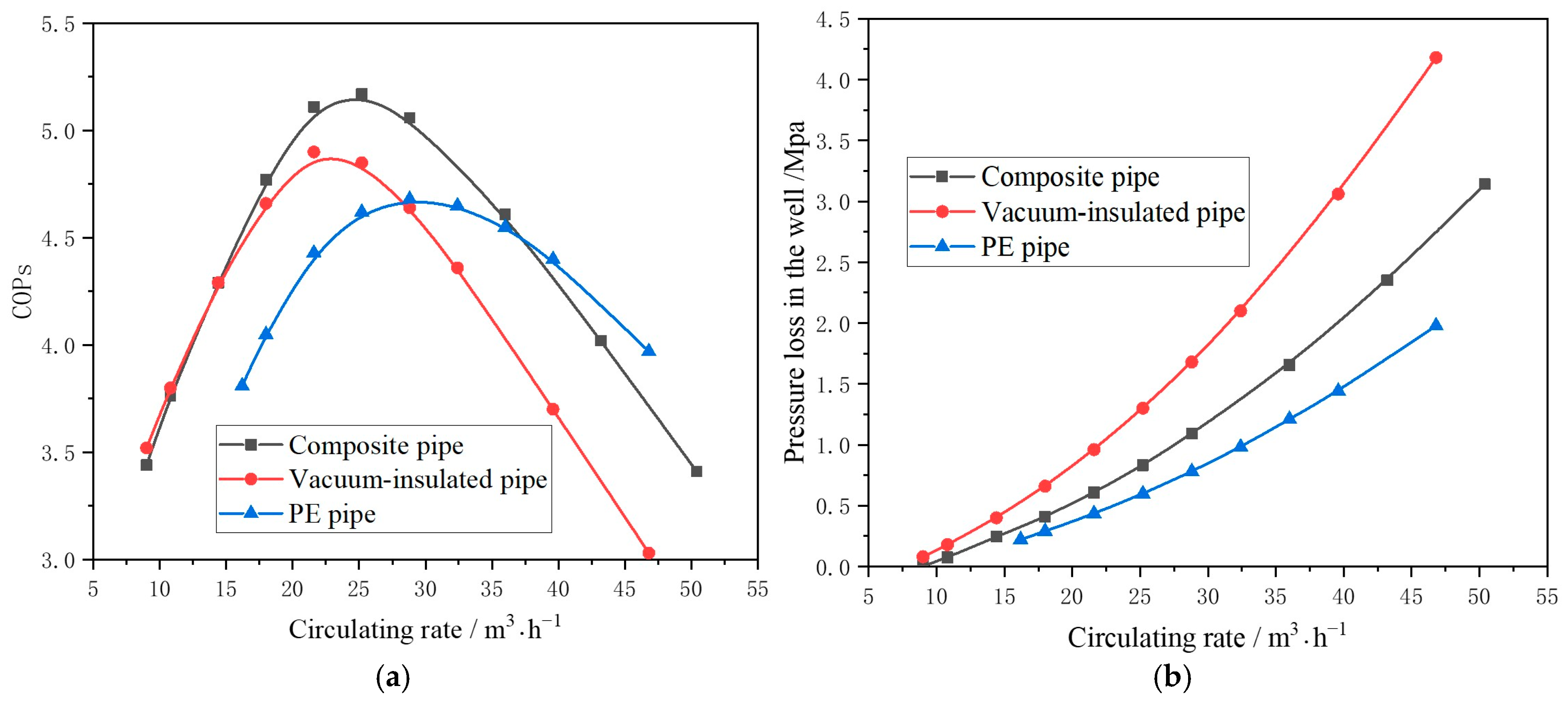
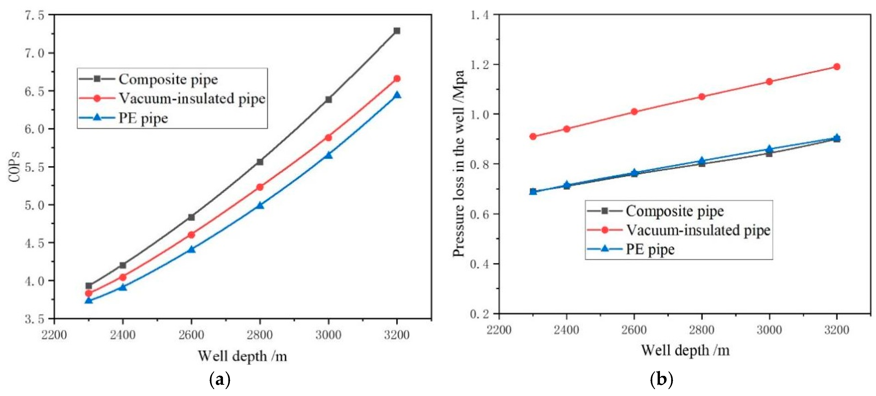
The operational performance of the composite central pipe was compared with existing PE central pipes and vacuum-insulated central pipes using a numerical simulation method. It was found that the utilization of the composite central pipe results in an 11% and 7% increase in the system’s COPs compared to traditional PE central pipes and vacuum-insulated central pipes, respectively.
However, due to insufficient research conditions, there are still some limitations in this study that need to be addressed in future research. Firstly, the composite pipe developed in this paper still uses HDPE as the inner and outer layers. When the temperature exceeds 120 °C, significant softening occurs, so this pipe cannot be used for geothermal wells with a depth of more than 3000 m. Secondly, the field testing on the influence of water hammer, high-altitude drop, and other dynamics on the mechanical properties of composite pipes is still insufficient.

Author Contributions

X.Z.: Conceptualization, Methodology, Writing—Original Draft. Z.Z.: Validation, Investigation. Z.G.: Resources. J.L.: Project administration. L.C.: Supervision. All authors have read and agreed to the published version of the manuscript.

Funding

This study is supported by Natural Science Foundation of Shaanxi province of China [grant number 2023-JC-YB-422] and Scientific Research Program Funded by Shaanxi Provincial Education Department [grant number 24JP140].

Data Availability Statement

The original contributions presented in the study are included in the article, further inquiries can be directed to the corresponding author.

Conflicts of Interest

Author Jiaojiao Lv was employed by the company Power China Northwest Engineering Corporation Limited. The remaining authors declare that the research was conducted in the absence of any commercial or financial relationships that could be construed as a potential conflict of interest.

Abbreviations

CpSpecific heat, J/(kg·°C)
ftpThe friction factor
gGravitational acceleration, 9.8 m/s2
hEnthalpy of the refrigerant, J/kg
wtCirculating rate of water in geothermal well, kg/s
LhpCirculating rate of refrigerant in heat pump, kg/s
LhThe mass flow rate of heating water, kg/s
PFluid pressure, Pa
QEThe heat release rate by refrigerant in condenser, W
QCThe heat absorption rate by refrigerant in evaporator, W
QheatingloadRequired district heating load, W
rThe wellbore radius, m
TFluidThe temperature of circulating fluid in geothermal well,·°C
TinInlet temperature of circulating fluid,·°C
ToutOutlet temperature of circulating fluid,·°C
TsThe supply water temperature,·°C
TbThe back water temperature,·°C
vVelocity, m/s
WpumpPower consumption of circulation pump, W
WPower consumption of heat pump, W
ZThe depth of the wellbore, m
αConvective heat transfer coefficient, J/(m2·s·°C)
λThermal conductivity, J/(m·K)
η1The compressor isentropic efficiency
η2Mechanical efficiency of the compressor
ηCHeat transfer efficiency of the condenser
ηEHeat transfer efficiency of the evaporator
θThe well angle to the horizontal line
ρDensity, kg/m3

References

  1. Glassley, W.E. Geothermal Energy: Renewable Energy and the Environment; CRC Press: London, UK, 2015. [Google Scholar]
  2. Kazaz, O.; Abu-Nada, E. Innovative high-energy nanocomposite absorbers for superior solar-driven water desalination through broadband solar energy harvesting. Appl. Therm. Eng. 2025, 273, 126531. [Google Scholar] [CrossRef]
  3. Kamila, Z.; Kaya, E.; Zarrouk, S.J. Reinjection in geothermal fields: An updated worldwide review 2020. Geothermics 2021, 89, 101970. [Google Scholar] [CrossRef]
  4. Figueira, J.S.; Gil, A.G.; Vieira, A.; Michopoulos, A.K.; Boon, D.P.; Loveridge, F.; Cecinato, F.; Götzl, G.; Epting, J.; Zosseder, K.; et al. Shallow geothermal energy systems for district heating and cooling networks: Review and technological progression through case studies. Renew. Energy 2024, 236, 121436. [Google Scholar] [CrossRef]
  5. Sapinska-Sliwa, A.; Rosen, M.A.; Gonet, A.; Sliwa, T. Deep Borehole Heat Exchangers—A Conceptual and Comparative Review. Int. J. Air-Cond. Refrig. 2016, 24, 1630001. [Google Scholar] [CrossRef]
  6. Alimonti, C.; Soldo, E.; Bocchetti, D.; Berardi, D. The wellbore heat exchangers: A technical review. Renew. Energy 2018, 123, 353–381. [Google Scholar] [CrossRef]
  7. Anand, R.; Li, A.; Huang, W.; Chen, J.; Li, Z.; Ma, Q.; Jiang, F. Super-long gravity heat pipe for geothermal energy exploitation—A effective review. Renew. Sustain. Energy Rev. 2024, 193, 114286. [Google Scholar] [CrossRef]
  8. Nath, F.; Mahmood, N.; Ofosu, E.; Khanal, A. Enhanced geothermal systems: A critical review of recent advancements and future potential for clean energy production. Geoenergy Sci. Eng. 2024, 243, 213370. [Google Scholar] [CrossRef]
  9. Zhang, X. Numerical study of geothermal district heating from a ground heat exchanger coupled with a heat pump system. Appl. Therm. Eng. 2021, 185, 116335. [Google Scholar] [CrossRef]
  10. Du, Y.S.; Feng, Y.S.; Wu, X.L.; Shi, M.; Gao, P.J.; Tang, X.R.; Zhao, Y.; Wang, X.S.; Wang, Q.X.; Dong, X.Y.; et al. Research status and consideration of thermal insulation pipe technology for deep geothermal energy development. Drilling Eng. 2022, 49, 138–145. (In Chinese) [Google Scholar] [CrossRef]
  11. Śliwa, T.; Kotyza, J. Application of existing wells as ground heat source for heat pumps in Poland. Appl. Energy 2003, 74, 3–8. [Google Scholar] [CrossRef]
  12. Zhu, Z.; Miao, Y.; Li, D.; Lin, X.; Ra, J.; Sun, Y.; Yu, W. Pilot test and effect evaluation of thermal insulation tubing. Energy Conserv. Petrol. Ind. 2019, 9, 12–14. (In Chinese) [Google Scholar] [CrossRef]
  13. Afra, M.; Peyghambarzadeh, S.; Shahbazi, K.; Tahmassebi, N. Experimental study of implementing nano thermal insulation coating on the steam injection tubes in enhanced oil recovery operation for reducing heat loss. J. Pet. Sci. Eng. 2020, 189, 107012. [Google Scholar] [CrossRef]
  14. Gao, Q.; Jin, G.; Yu, H.; An, E.; Ghassemi, A.; Zhou, D.; Meng, H. Heat extraction from abandoned petroleum wells utilizing coaxial borehole heat exchanger in Ordos basin, China. Renew. Energy 2024, 230, 120806. [Google Scholar] [CrossRef]
  15. Dijkshoorn, L.; Speer, S.; Pechnig, R. Measurements and Design Calculations for a Deep Coaxial Borehole Heat Exchanger in Aachen, Germany. Int. J. Geophys. 2013, 14, 916541. [Google Scholar] [CrossRef]
  16. Li, C.; Guan, Y.; Yang, R.; Lu, X.; Xiong, W.; Long, A. Effect of inner pipe type on the heat transfer performance of deep-buried coaxial double-pipe heat exchangers. Renew. Energy 2020, 145, 1049–1060. [Google Scholar] [CrossRef]
  17. Deng, J.; Wei, Q.; Liang, M.; He, S.; Zhang, H. Does heat pumps perform energy efficiently as we expected: Field tests and evaluations on various kinds of heat pump systems for space heating. Energy Build. 2018, 182, 172–186. [Google Scholar] [CrossRef]
  18. Deng, J.; Wei, Q.; Liang, M.; He, S.; Zhang, H. Field test on energy performance of medium-depth geothermal heat pump systems (MD-GHPs). Energy Build. 2019, 184, 289–299. [Google Scholar] [CrossRef]
  19. Liu, B.; Wang, J.; Li, H.; Liu, J.; Wang, P.; Cai, W.; Sun, X.; Chen, C. In-situ test and numerical investigation on the long term performance of deep borehole heat exchanger coupled heat pump heating system. Case Stud. Therm. Eng. 2024, 61, 104855. [Google Scholar] [CrossRef]
  20. Xie, Y.Y. Research on the Potential and Model of Geothermal Heating in the Middle and DEEP Layers of Song Yuan. Ph.D. Thesis, Jilin University, Changchun, China, 2019. [Google Scholar]
  21. Song, X.; Zheng, R.; Li, G.; Shi, Y.; Wang, G.; Li, J. Heat extraction performance of a downhole coaxial heat exchanger geothermal system by considering fluid flow in the reservoir. Geothermics 2018, 76, 190–200. [Google Scholar] [CrossRef]
  22. Nian, Y.-L.; Cheng, W.-L. Evaluation of geothermal heating from abandoned oil wells. Energy 2018, 142, 592–607. [Google Scholar] [CrossRef]
  23. Moran, M.J. Fundamentals of Engineering Thermodynamics; John Wiley Press: Hoboken, NJ, USA, 2019. [Google Scholar]
  24. Li, H.; Wang, J.; Liu, S.; Tang, L.; Zhang, X.; Wang, P. Study on heat extraction capacity of deep coaxial borehole heat exchanger equipped with spiral-finned inner tube. Int. J. Heat Fluid Flow 2025, 116, 109946. [Google Scholar] [CrossRef]
  25. GB/T 10297; Test Method for Thermal Conductivity of Nonmetal Solid Materials—Hot-Wire Method. Standards Press of China: Beijing, China, 2015.
  26. GB/T 10296; Thermal Insulation-Determination of Steady-State Thermal Transmission Properties-Pipe Insulation Apparatus. Standards Press of China: Beijing, China, 2008.
  27. GB/T 8804; Thermoplastic Pipes—Determination of Tensile Properties. Standards Press of China: Beijing, China, 2013.
Figure 1. Schematic diagram of the MD-GHP system.
Energies 18 03713 g001
Figure 2. Flowchart of the solution.
Energies 18 03713 g002
Figure 3. Schematic of the test system.
Energies 18 03713 g003
Figure 4. Variation in (a) inlet temperature, (b) circulating rate, and (c) heat load of water-cooling tower during the experiment.
Energies 18 03713 g004
Figure 5. Variation in (a) outlet temperature, (b) pressure loss in the well, and (c) power consumption of heat pump during the experiment.
Energies 18 03713 g005
Figure 6. Optimal central pipe size for different effective thermal conductivities of central pipe.
Energies 18 03713 g006
Figure 7. Variation in calculated COPs with the effective thermal conductivity of the central pipe at the optimal size.
Energies 18 03713 g007
Figure 8. Composite central pipe structure.
Energies 18 03713 g008
Figure 9. The tested thermal conductivity of (a) the composition materials and (b) the composite central pipe.
Energies 18 03713 g009
Figure 10. (a) High-temperature tensile testing process and (b) tension–displacement curves at 105 °C for the composite central pipe.
Energies 18 03713 g010
Figure 11. Variation in calculated (a) COPs and (b) pressure loss in the well with circulating rates for different central pipes.
Energies 18 03713 g011
Figure 12. Variation in calculated (a) COPs and (b) pressure loss in the well with geothermal well depth for different central pipes.
Energies 18 03713 g012
Table 1. The main parameters of the system.
Parameter ValueParameter Value
Wellbore depth, m2700Measured formation temperature gradient, °C/100 m3.1
Borehole diameter, mm222Circulating water flow, m3/h24
Outer diameter of casing, mm177.8Heating load, kW400
Inner diameter of casing, mm159.4Heating water temperature, °C45
CementingClass G
Table 2. Orthogonal experimental table.
Num.dtiδtλtCOPs
(Calculated)
Num.dtiδtλtCOPs
(Calculated)
174201.264.161974100.204.81
278100.035.072078141.264.08
382140.204.852182180.035.24
486203.163.642274123.163.59
590120.085.052378160.085.02
694160.504.472482200.504.78
786100.504.682586161.264.08
890143.163.512690200.035.12
994180.084.822794120.204.95
1074200.084.912886140.085.17
1178120.504.662990180.504.83
1282163.163.683094103.163.52
1386180.204.883186120.085.23
1490101.263.503290160.205.15
1594140.035.163394201.263.75
1674160.035.083474140.504.43
1778200.205.133578183.163.67
1882121.263.873682100.085.13
Disclaimer/Publisher’s Note: The statements, opinions and data contained in all publications are solely those of the individual author(s) and contributor(s) and not of MDPI and/or the editor(s). MDPI and/or the editor(s) disclaim responsibility for any injury to people or property resulting from any ideas, methods, instructions or products referred to in the content.

