Article

A Less-Rare-Earth Permanent Magnet Machine with Hybrid Magnet Configuration for Electric Vehicles

School of Electrical Engineering, Southeast University, Nanjing 210096, China
*
Author to whom correspondence should be addressed.
Energies 2025, 18(12), 3051; https://doi.org/10.3390/en18123051
Submission received: 16 April 2025 / Revised: 28 May 2025 / Accepted: 31 May 2025 / Published: 9 June 2025

Abstract

This paper proposes a novel hybrid less-rare-earth permanent magnet (HLEPM) machine, which is designed to meet the demands of electric vehicle (EV) traction machines for high torque output and wide-speed-range high-efficiency performance. The designed machine features a unique hybrid permanent magnet arrangement, consisting of V-shaped rare-earth PMs and arc-shaped less-rare-earth PMs, respectively. The V-shaped rare-earth magnets can perform the flux-focusing effect well, not only enhancing the torque output capability but also improving the demagnetization with the standability of the arc-shaped less-rare-earth PMs during active short-circuit (ASC) conditions. First, the proposed machine is thoroughly designed and optimized to balance the torque capability and iron loss. Subsequently, the electromagnetic performance of the proposed HLEPM machine is evaluated using finite-element (FE) analysis and compared with that of a conventional double-layer V-shaped PMSM. Finally, the anti-demagnetization characteristics of the two machines under ASC conditions are analyzed in detail. The results validate the rationality and reliability of the proposed design.

1. Introduction

In recent years, with the increasing severity of environmental pollution and energy shortages, to effectively mitigate the pressing conflicts arising from these problems, electric vehicles have become one of the key directions for global promotion and development [1,2]. Traditional permanent magnet synchronous machines (PMSMs) are widely used in electric vehicles due to their high torque density and efficiency [3,4]. However, the scarcity and high cost of rare-earth resources have limited their large-scale application in PMSM [5]. To reduce the dependency of PMSMs on rare-earth PM materials, rare-earth-free or less-rare-earth machines have attracted significant attention and in-depth research worldwide [6,7,8]. By optimizing machine structure design and fully utilizing reluctance torque, the torque output capability of machines can be effectively enhanced.
Ferrite, serving as a critical material in rare-earth-free PM machines, has emerged as an essential excitation source in a variety of such machines, owing to its abundant natural reserves and cost-effectiveness [9,10,11]. The adoption of large-area ferrite PMs effectively increases the air-gap magnetic flux density, thereby boosting the output torque. Additionally, the optimization of the rotor space and incorporating slots on the d-axis can further enhance the reluctance torque. Nevertheless, the extensive application of less-rare-earth PMs may compromise the mechanical strength of the rotor, and the torque enhancement capability remains limited, unable to match the electromagnetic performance of conventional permanent magnet machines. Therefore, less-rare-earth hybrid PM materials have emerged as a research hotspot, as these machines can significantly improve torque output while reducing manufacturing costs [6,12,13,14,15,16,17]. By combining rare-earth PMs with non-rare-earth PMs [6,12,13], and ensuring a higher proportion of ferrite magnets compared to rare-earth magnets, along with optimizing the arrangement of PMs, the machine performance can be effectively improved, and accidental demagnetization can be avoided. Furthermore, the integration of hybrid PM materials with flux-switching machines can enhance the wide-range high-efficiency performance of machines while reducing costs [14,15,16,17]. Meanwhile, the development of novel dual-phase magnetic materials effectively reduces leakage flux in multi-layer machine structures [18], significantly enhancing electromagnetic performance. Compared to conventional PMSMs, the proposed design demonstrates superior operational efficiency across both low- and high-speed regimes, offering a promising technical pathway for high-performance rare-earth-free permanent magnet machines. However, rare-earth-free or less-rare-earth PM machines are prone to accidental demagnetization under active short-circuit (ASC) conditions in electric vehicles, due to the use of magnets with low coercivity and magnetic energy product [19,20,21]. Through a comprehensive investigation of how the structural parameters of the machine influence short-circuit currents and PM demagnetization characteristics [22,23], the study optimizes the dimensional design of PM machines and proposes a generalized analytical framework to determine safe operating boundaries for short-circuit currents and demagnetization thresholds across varying temperature and speed conditions, thereby effectively mitigating ASC-induced PM demagnetization risks. Therefore, achieving a balance between cost, electromagnetic performance, and anti-demagnetization capability in less-rare-earth machines has become a key research focus.
In order to address the forgoing tradeoff, this paper proposes a novel hybrid less-rare-earth permanent magnet (HLEPM) machine. (1) The first layer of the proposed HLEPM machine employs a V-shaped rare-earth PM to provide excellent torque performance, while the second layer utilizes arc-shaped less-rare-earth PM to increase the machine saliency ratio and hence the flux-focusing effects. (2) The dual-layer hybrid less-rare-earth design not only ensures excellent reluctance torque capability, but also effectively reduces machine costs due to the predominant proportion of less-rare-earth PMs. (3) The hybrid-shaped PM’s arrangement and magnetic bridge structure design of the proposed HLEPM machine effectively increase the width for circulating the armature reaction magnetic fields, enhancing the demagnetization resistance of the machine under ASC conditions.
This paper is organized as follows: Section 2 details the machine’s topology and design specifications. Section 3 compares the electromagnetic performance of the proposed machine with a conventional PMSM under the same dimensional constraints, validating the superior performance of the proposed machine. In Section 4, the anti-demagnetization characteristics of the two machines under ASC conditions are evaluated and analyzed. In Section 5, a machine prototype is fabricated and tested to verify the theoretical and FE analyses.

2. Design Approach and Specifications of the Proposed Machine

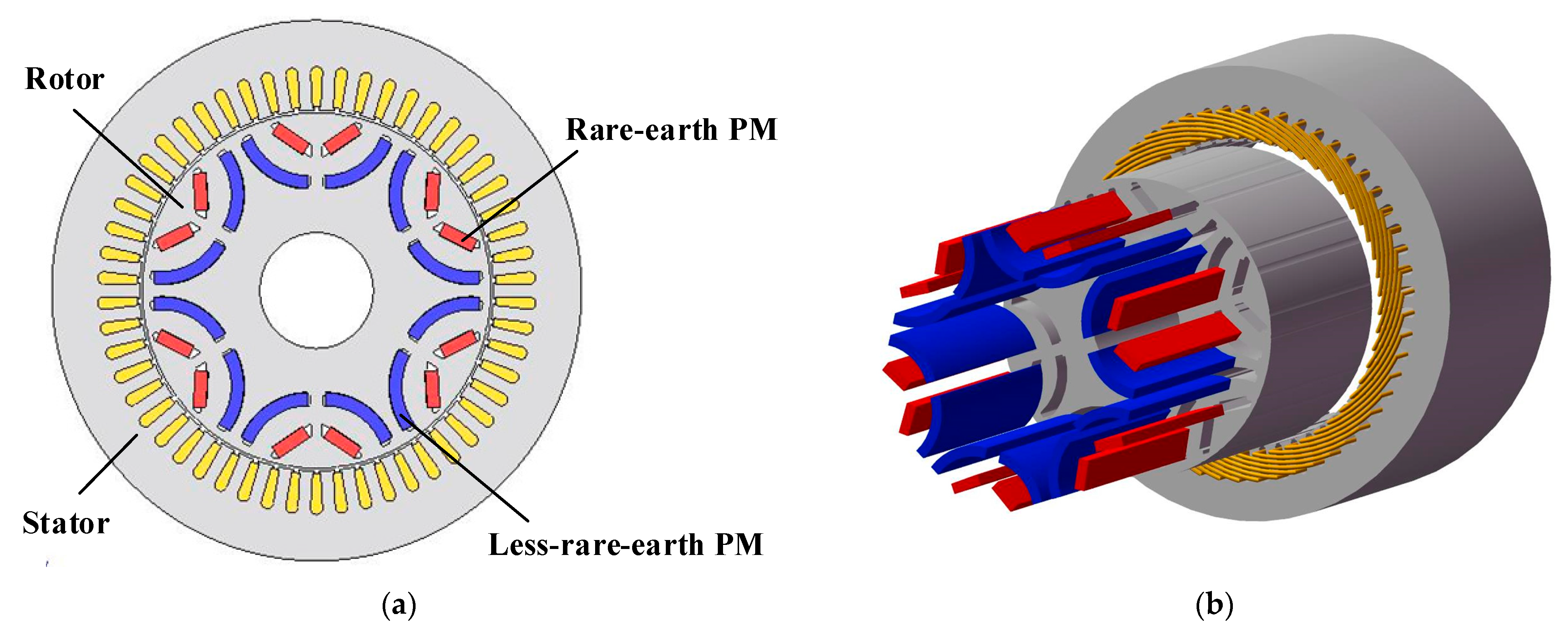
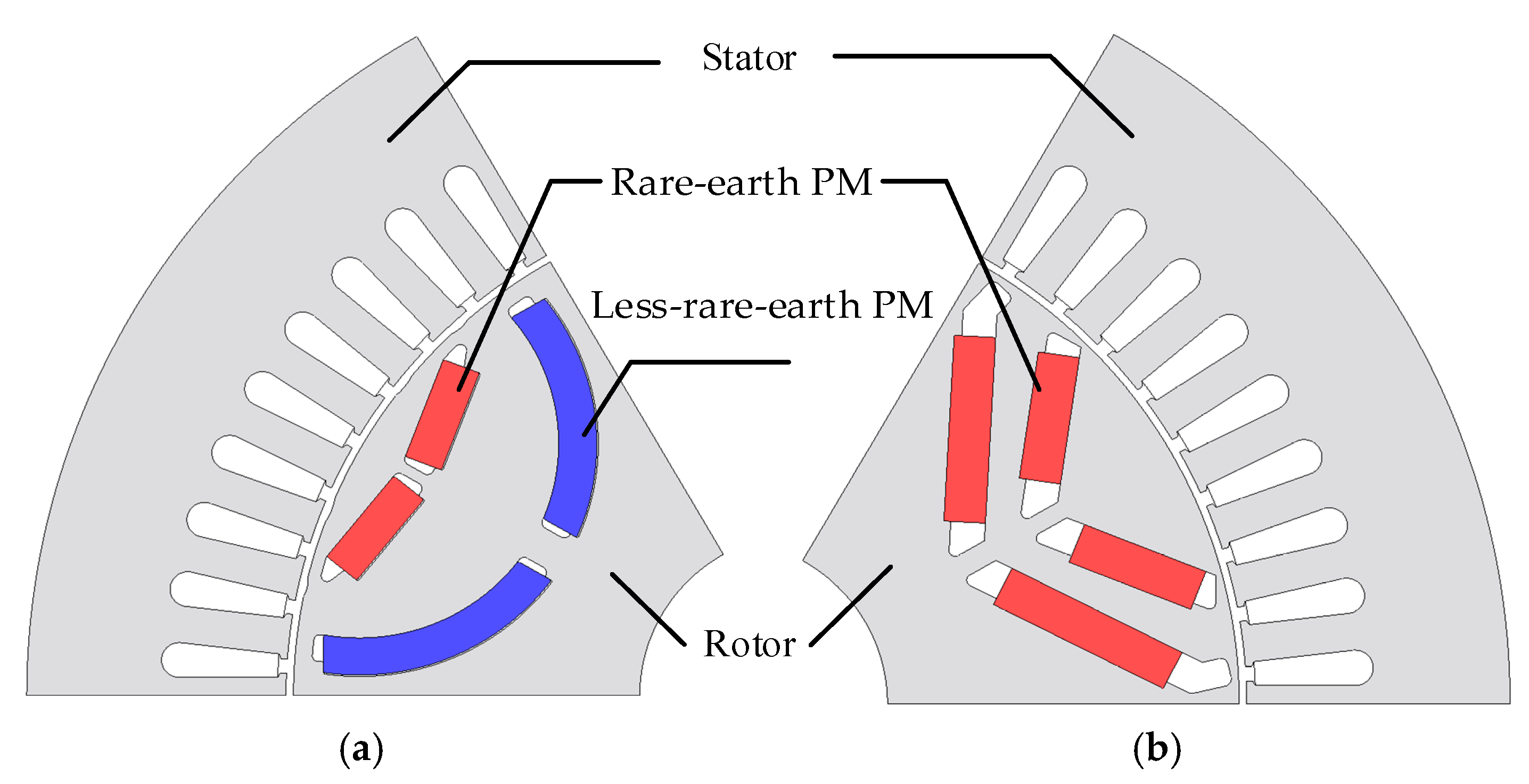
2.1. Propose Topology

Figure 1 illustrates the topology and exploded view of the proposed HLEPM machine, which features a hybrid PM structure comprising arc-shaped specially formulated less-rare-earth PMs (with reduced dysprosium or terbium content) and V-shaped rare-earth PMs. The machine is designed with a 54-slot/6-pole configuration. The proposed machine incorporates optimized structural design and strategic permanent magnet arrangement to achieve the high torque output and wide-range efficiency that electric vehicles require.
The proposed HLEPM machine exhibits the following key features:
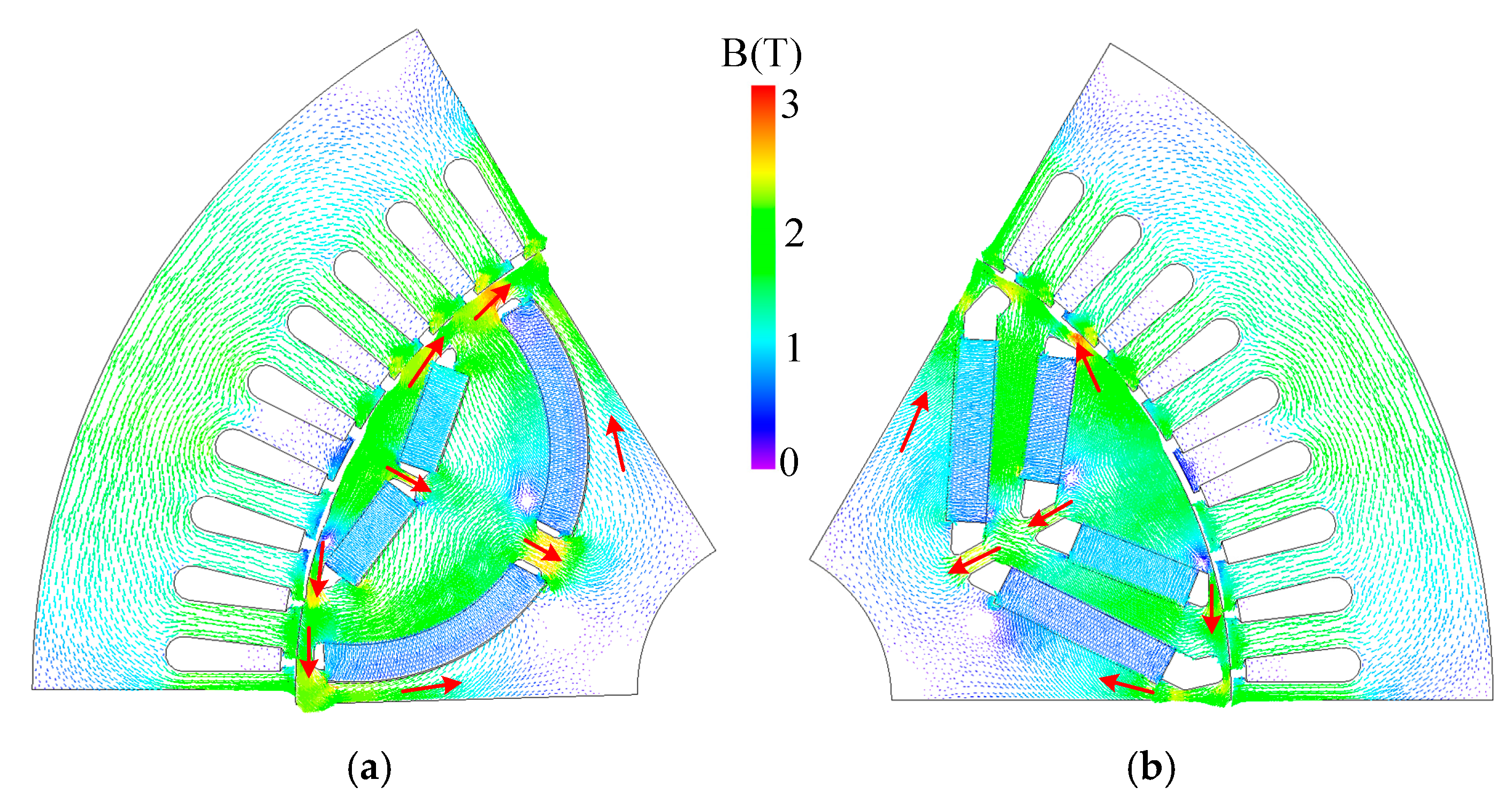
  • The first layer employs a V-shaped rare-earth PM, primarily providing a high torque output capability and protecting the second layer of magnets from demagnetization currents particularly under ASC conditions, thereby enhancing their anti-demagnetization capability.
  • The second layer incorporates an arc-shaped less-rare-earth PM, which increases the saliency ratio and significantly enhances the flux-focusing effects, thereby improving torque density. Additionally, the cost of this design is approximately one-third compared to traditional PM machines.
  • The proposed HLEPM machine meets high torque output requirements, exhibits high efficiency from medium- to high-speed ranges, and effectively mitigates the risk of accidental demagnetization of PMs under ASC conditions.
It is noteworthy that the proposed HLEPM machine not only provides high output torque and significant flux-focusing effects but also exhibits high efficiency, as well as high output power in the field-weakening speed range due to its V-shaped and arc-shaped PM structures. Furthermore, the proposed structure demonstrates strong resistance to demagnetization under ASC conditions, making it highly suitable for the demanding operational environment of electric vehicles.

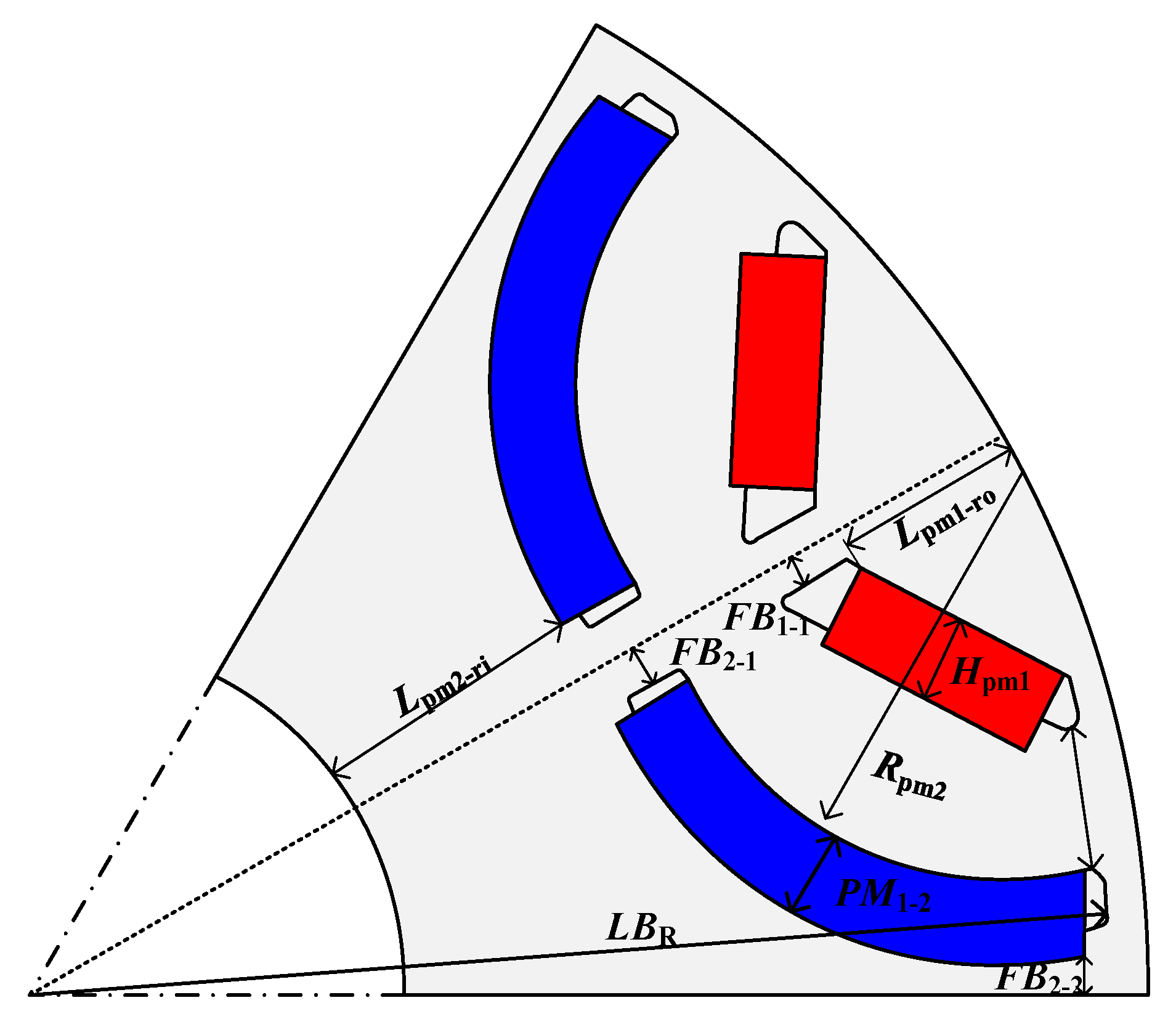
2.2. Specifications and Dimensions
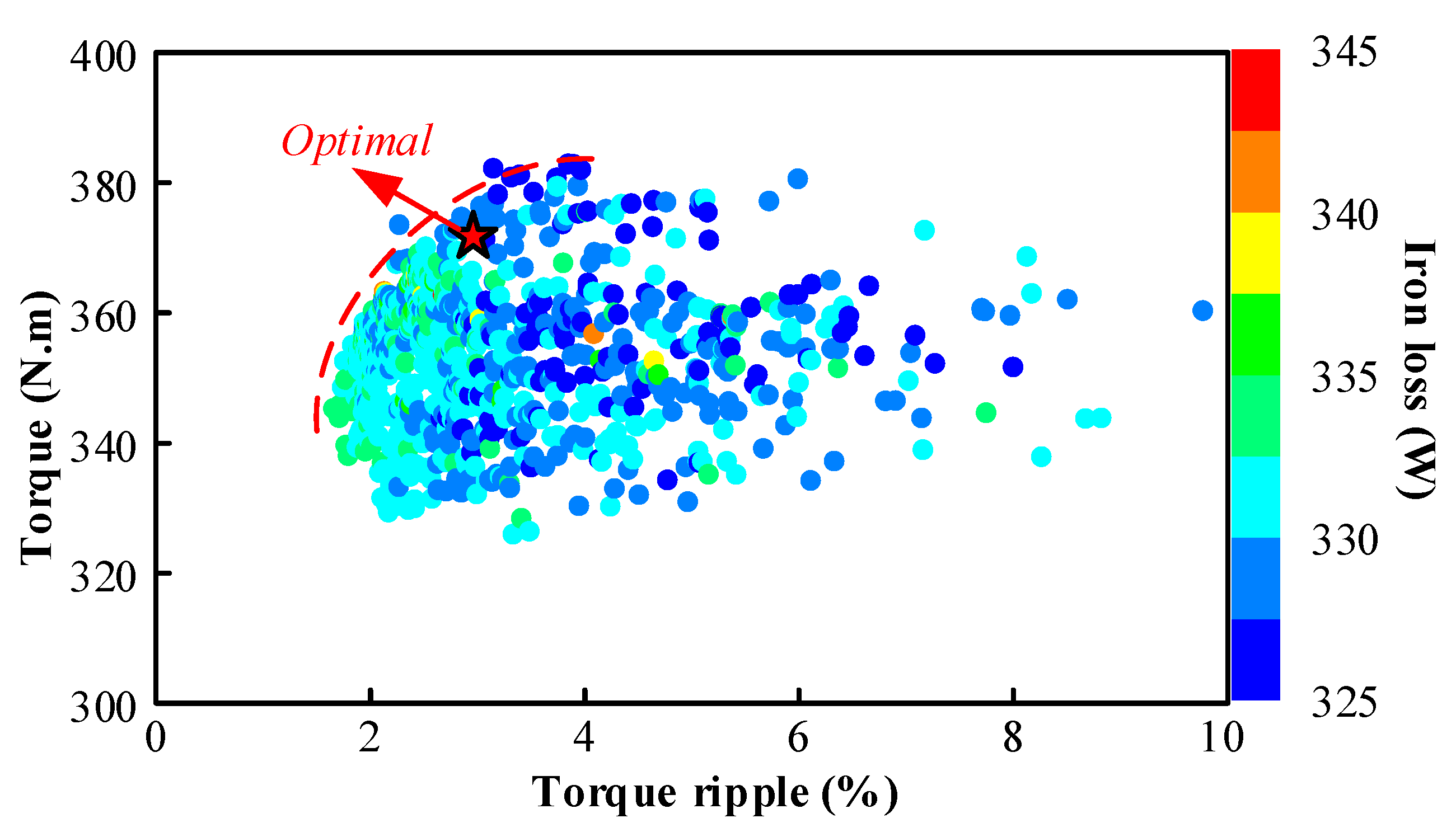
The HLEPM machine utilizes hybrid PMs—specifically, the V-shaped rare-earth magnets, exhibiting a remanence of 1.21 T at 100 °C, and the arc-shaped less-rare-earth magnets exhibiting a remanence of 1.12 T at 100 °C. The less-rare-earth magnets are characterized by a lower content of the rare-earth elements Dy and Tb. The B-H curves for both magnet grades are depicted in Figure 2. The material properties of the HLEPM machine are shown in Table 1. The designed machine targets a maximum output torque of 360 Nm and a maximum power of 200 kW. The primary parameters of the machine are detailed in Table 2.

2.3. Optimization

In Figure 3, the rotor is parameterized and modeled for the further optimization. To achieve the desired performance, a multi-objective genetic algorithm is utilized for the optimization of the proposed machine. The optimization criteria encompasses output torque, torque ripple, and iron loss. The optimization objectives and weights are listed in Table 3, while the parameter optimization ranges are detailed in Table 4. Figure 4 shows the scatter plot of the optimization results, and the optimal point is selected and marked based on the optimization indicators of a torque higher than 360 Nm, minimum torque ripple, and an iron loss of less than 330 W. Following a thorough evaluation, the optimal design parameters are identified as 369.5 Nm, 3%, and 324.45 W, respectively.

3. Electromagnetic Performance of Electric Machine

To comprehensively demonstrate the superiority of the HLEPM machine, a comparative analysis is conducted against a conventional PMSM, as illustrated in Figure 5. The key difference between the proposed HLEPM machine and the traditional PMSM is the arc-shaped design of the second layer of PM, which utilizes a less-rare-earth PM. To ensure a fair comparison, some critical parameters including the stator and rotor dimensions, slot–pole configuration, winding arrangement, and PM volume are maintained as identical for the two machines. Specifically, the HLEPM machine features an arc-shaped less-rare-earth PM accounting for 69% and a V-shaped rare-earth PM accounting for 31%. Cost comparison data of the two machines are shown in Table 5. The main difference in machine costs can be attributed to the PMs. The cost of the HLEPM machine is approximately 10% lower than that of the conventional PMSM.

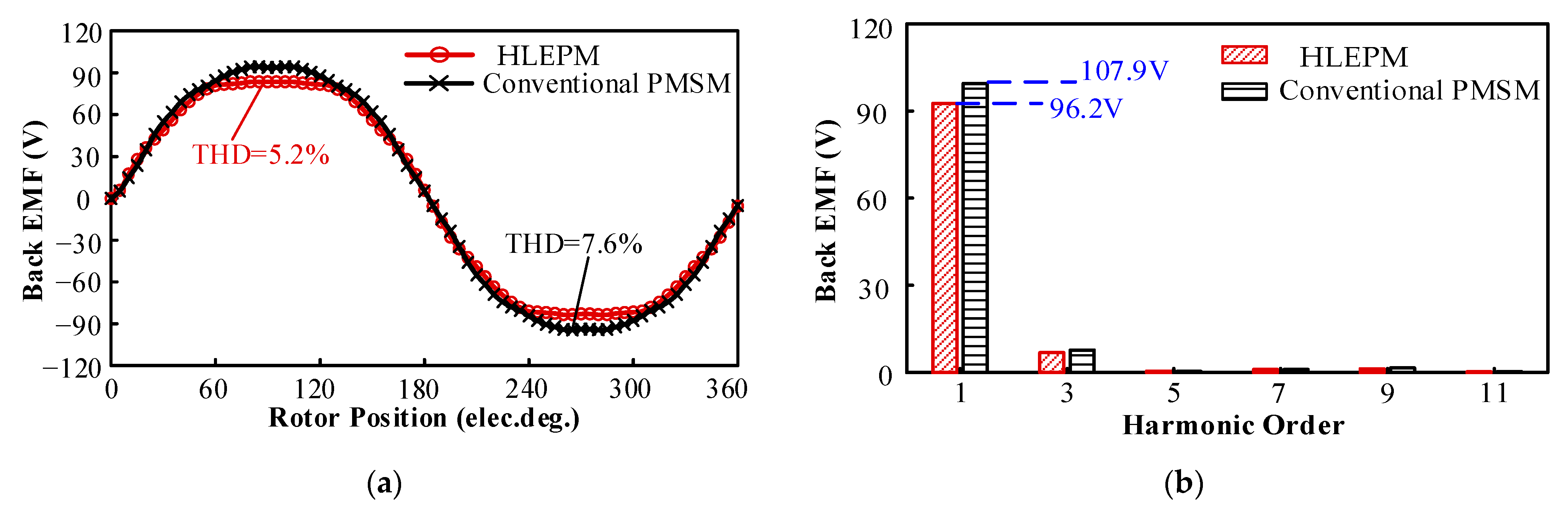
3.1. No-Load Performance

The no-load air-gap magnetic flux density waveforms of both machines are depicted in Figure 6. The fundamental amplitudes of the air-gap flux density for the HLEPM machine and the conventional PMSM are approximately 0.87 T and 0.95 T, respectively. Additionally, the corresponding back electromotive force (EMF) waveforms are presented in Figure 7, with fundamental amplitudes of 96.2 V and 107.9 V, respectively. It is evident that the air-gap flux density and the fundamental back EMF amplitude of the proposed machine are marginally lower than those of the conventional PMSM, which is attributed to the adoption of a less-rare-earth PM in the second arc-shaped layer. Additionally, the HLEPM machine exhibits a notable reduction in harmonic content compared to the conventional PMSM due to the hybrid magnet configuration design combining a V-shaped rare-earth PM with an arc-shaped less-rare-earth PM.

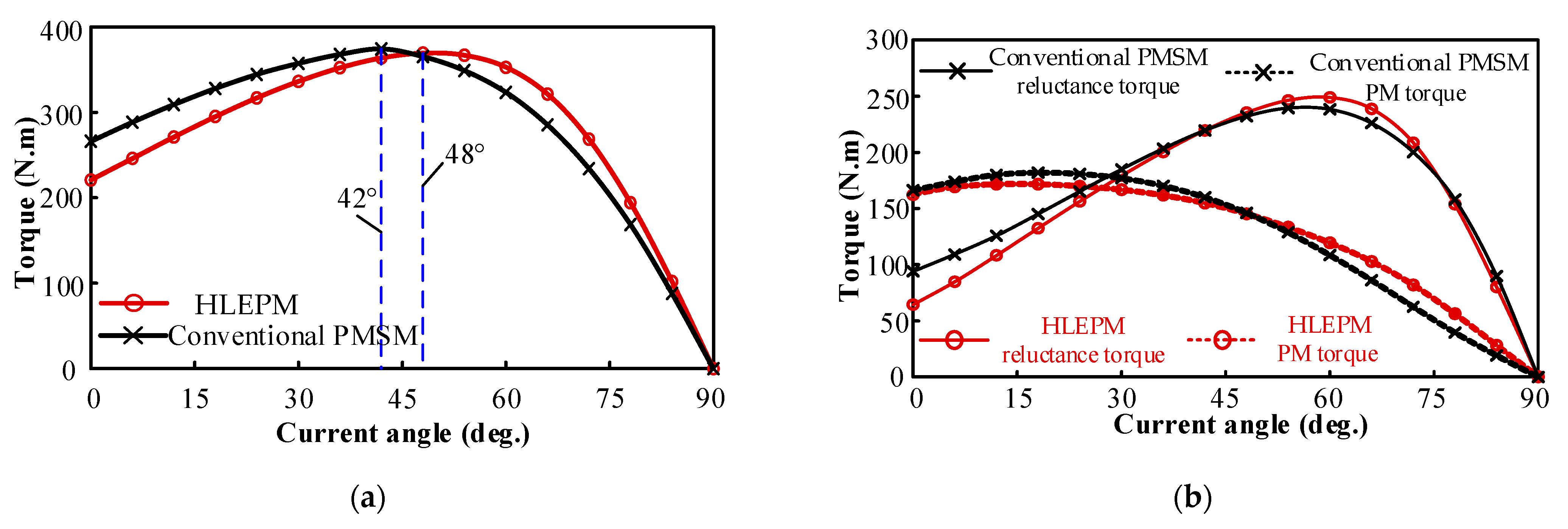
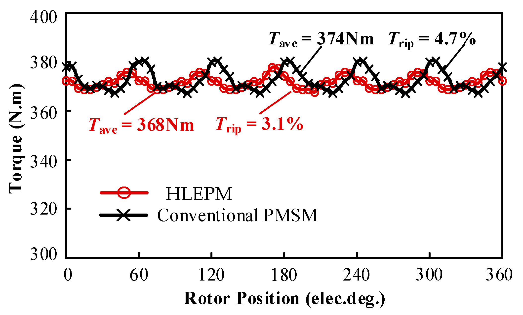
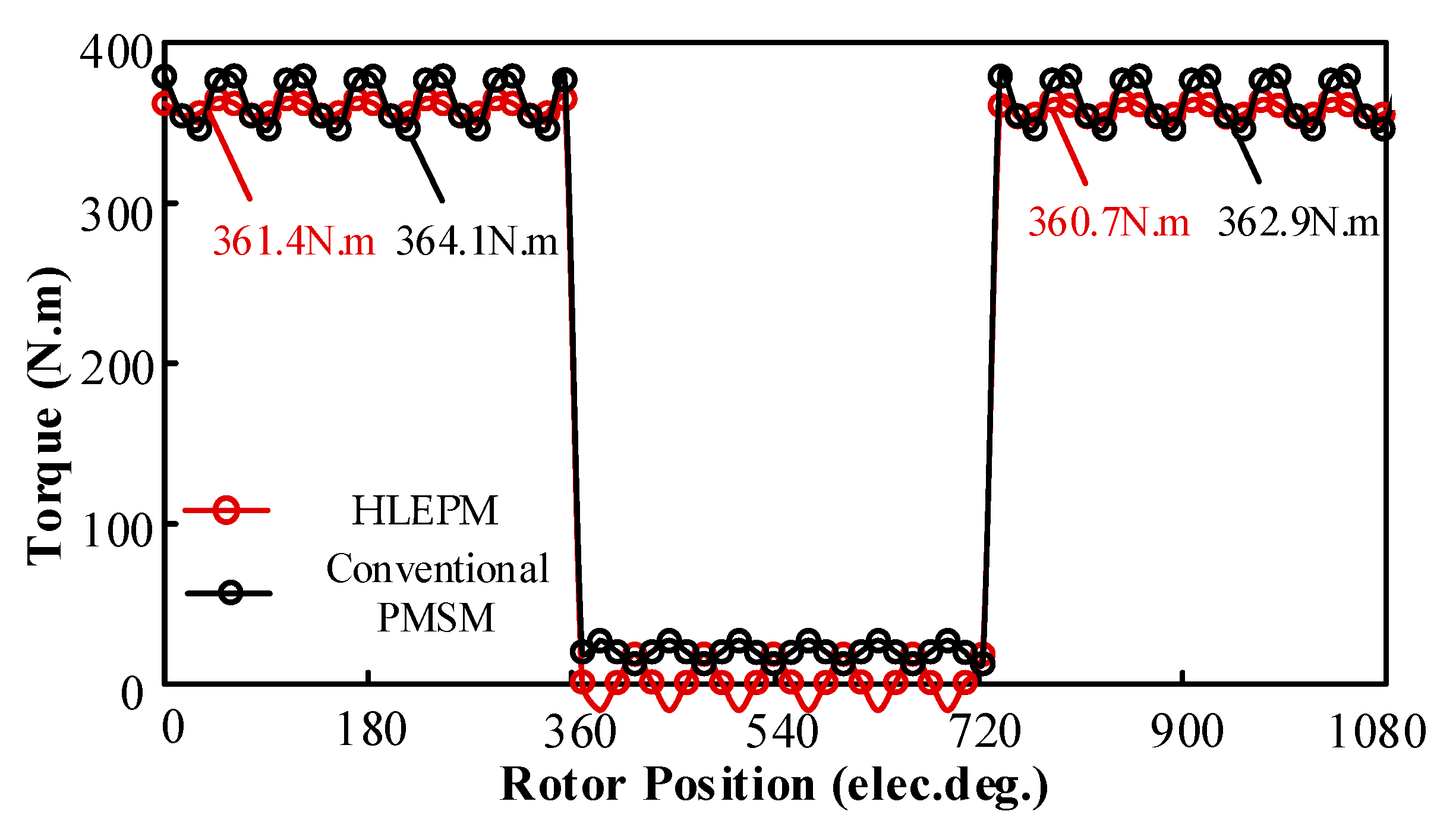
3.2. Load Performance

Figure 8 depicts the variation in the average output torque as a function of the current angle for the two machines. The optimal current angles for the HLEPM machine and the conventional PMSM are observed to be 42° and 48°, respectively. This finding suggests that the adoption of a less-rare-earth PM in the arc-shaped layer of the proposed machine leads to a notable increase in the saliency ratio, resulting in a more pronounced contribution from reluctance torque.
The steady-state-torque waveforms at 4500 rpm of both machines are shown in Figure 9, with values of 368 Nm and 374 Nm. The torque ripples for the two machines are measured at 3.1% and 4.7%, respectively. Notably, the conventional PMSM exhibits a higher torque ripple, which is mainly attributed to the larger rare-earth PM usage, and the total harmonic distortion (THD) is higher than the HLEPM machine.

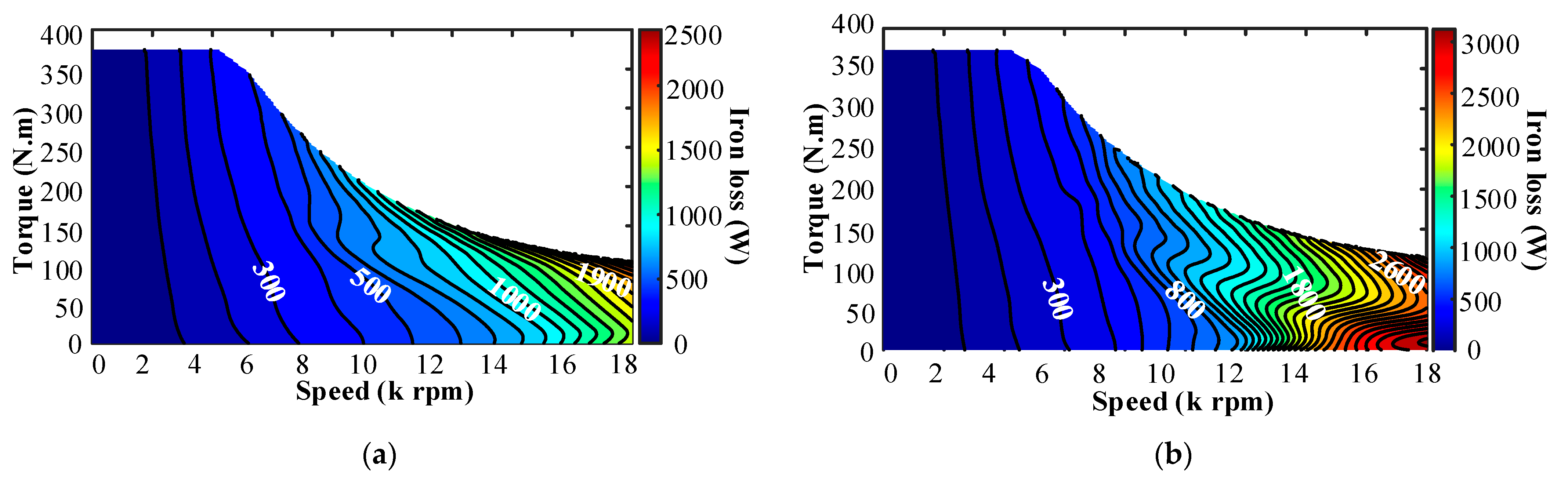
3.3. Loss Characteristics
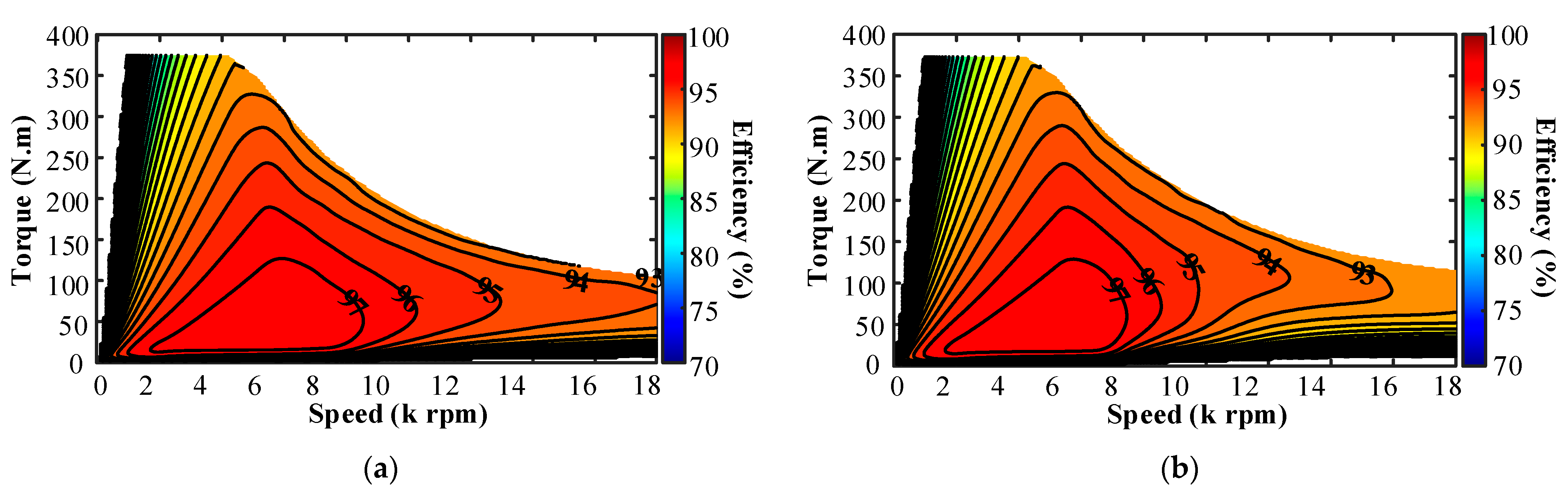
The copper loss characteristics of the two machines are depicted in Figure 10. It can be found that the copper losses of the two machines exhibit minimal differences in the low-speed range. In contrast, the HLEPM machine demonstrates significantly lower copper losses compared to the conventional PMSM in the high-speed range, with the maximum difference reaching 3000 W. This reduction is mainly due to the decreased magnetic flux caused by the implementation of an arc-shaped less-rare-earth PM in the proposed machine, which consequently reduces the required flux-weakening copper losses.
On the other hand, the iron loss distributions of the two machines are illustrated in Figure 11. The HLEPM machine exhibits significantly lower iron losses compared to the conventional PMSM, especially in the medium- to high-speed ranges. This reduction is mainly attributed to the decreased magnetic flux generated by the arc-shaped less-rare-earth PM in the proposed machine during high-speed field-weakening operation, which leads to a substantial decrease in iron losses. The copper and iron losses for both machines at the speed of 4500 rpm and the rated torque of 368 Nm are presented in Table 6.

3.4. Efficiency

The efficiency maps of the two machines are demonstrated in Figure 12, achieving maximum peaks of 97.94% and 97.95%, respectively. As shown in the efficiency maps, the proposed machine demonstrates a notably higher efficiency in the medium- to high-speed ranges compared to the conventional PMSM. As shown in Table 7, the region with an efficiency exceeding 95% in the medium-speed range expands from 10,600 rpm to 13,800 rpm, indicating a 30% improvement. Likewise, the region with an efficiency exceeding 94% in the high-speed range extends from 13,500 rpm to 18,000 rpm, indicating a 33% improvement. These results highlight the proposed machine’s significant contribution to efficiency enhancement in the medium- to high-speed regions. The maximum efficiency and maximum power values at the speed of 4500 rpm are detailed in Table 8.

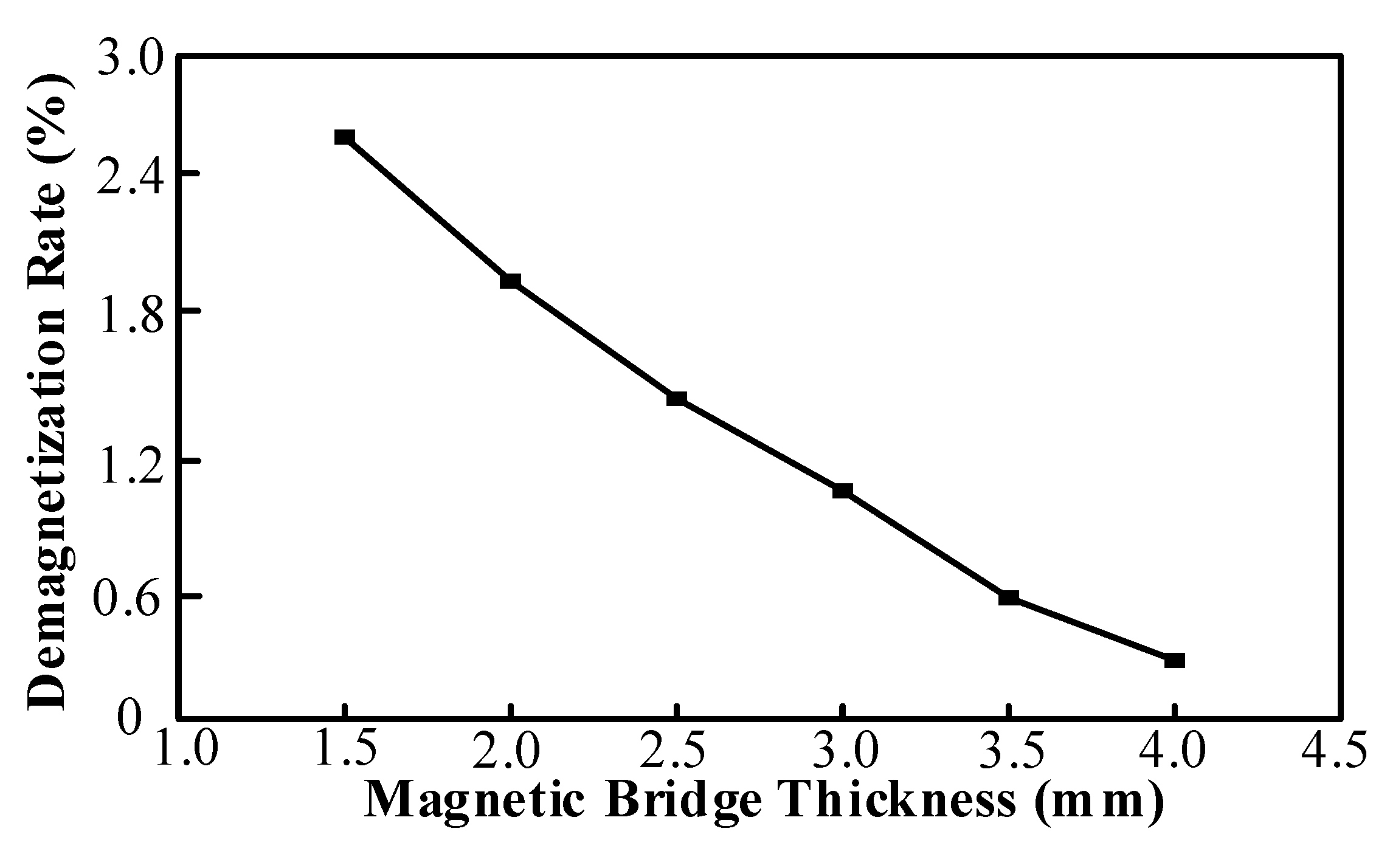
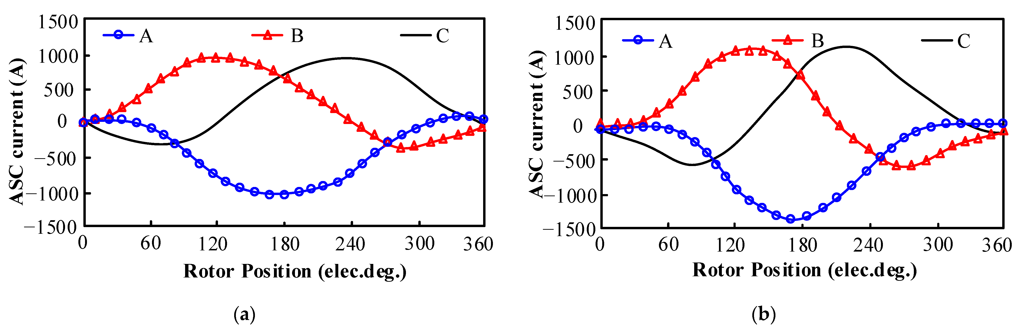
4. Demagnetization Analysis Under ASC Operating Condition

The application of less-rare-earth PMs poses a considerable challenge in mitigating demagnetization. Consequently, this study investigates the demagnetization behavior of the proposed machine under ASC conditions. Table 9 and Figure 13 present the demagnetization rates of the HLEPM machine under different magnetic bridge thicknesses. The data show that adding auxiliary magnetic bridges and selecting reasonable bridge thickness can create a pathway for the magnetic field generated by demagnetizing currents. Figure 14 presents the demagnetization distribution contour of the PMs at 100 °C. The corresponding magnetic field distributions are shown in Figure 15, where red arrows indicate the magnetic field paths. This mechanism reduces the impact of demagnetizing fields on PMs, thereby significantly enhancing the demagnetization resistance of less-rare-earth PMs.
The proportions of demagnetization rates exceeding 5% and the torque reduction rates for the HLEPM machine and the conventional PMSM are presented in Table 10. The results indicate that the HLEPM machine exhibits a lower proportion of demagnetization rates exceeding 5% compared to the conventional PMSM, along with a reduced torque reduction rate in Figure 16. The design meets the requirements that the area proportion of permanent magnets with a demagnetization rate exceeding 5% is less than 2% and the torque reduction rate is lower than 1%. As shown in Figure 17, the ASC current of the HLEPM is lower than that of the conventional PMSM. These results indicate that the rare-earth PMs provide magnetic reinforcement to the less-rare-earth PMs, thereby elevating their operating points.

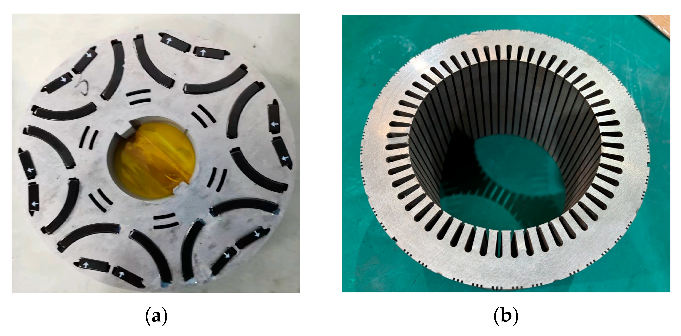
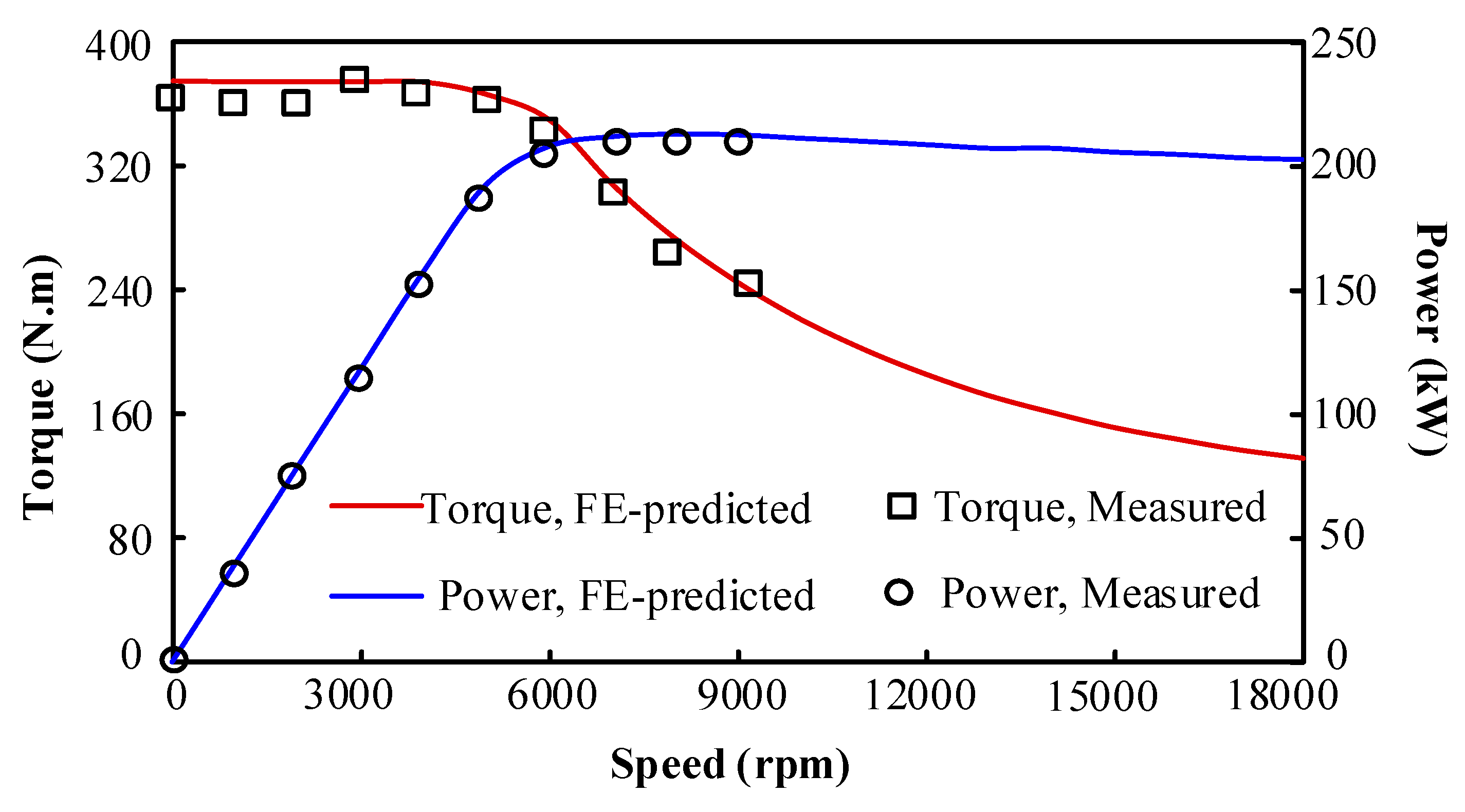
5. Experimental Validation

In order to validate the above analyses, a prototype of the proposed HLEPM is fabricated and tested. The prototype is shown in Figure 18.
Regarding the used dynamometer, the AVL e-Drive is primarily employed for measurements in the motor drive test with a power rating of over 200 kW.
The prototype testing platform consists of a servo machine, a torque meter (T40MS, from HBM, Darmstadt, Germany), and the prototype. Two sets of inverter systems are employed to drive the machines, each mainly consisting of FF300R12ME4 modules (switching devices, from Infineon, Neubiberg, Germany), TMS320F28379D (digital controller, from TI, Dallas, TX, USA), LF 510-S (current sensor, from LEM, Geneva, Switzerland), LV 25-P (voltage sensor, from LEM, Geneva, Switzerland), 3F88L-RS17 (resolver, from OMRON, Kyoto, Japan), etc.
It should be further mentioned that due to the cooperative company policy, the test platform is under confidentiality, so that the specific demonstration figures will not be provided in the current manuscript. A similar test platform description can be referenced and found in [24].
The no-load back-EMF waveforms obtained from both FE-predicted and tested are shown in Figure 19. The fundamental amplitude of the tested line–line voltage is 165.4 V, which is lower than the FE-predicted value of is 166.6 V. This discrepancy is primarily attributed to the fact that manufacturing errors in the machine are not considered in FE analyses.
Figure 20 shows the external characteristic curve derived from FE-predicted and experimental testing. The torque–speed curve shows the trend of the experimental test points aligns well with the FE-predicted curve. The peak torque reaches 366.2 Nm, but compared to the finite-element FE-predicted results, the constant-torque region in the prototype test is narrower, and deviations occur at different speeds. These discrepancies arise from speed fluctuations during testing and structural tolerances in the machine. The power–speed curve shows that the prototype test results generally match the FEA simulation. At 6000 rpm, the FE-predicted output power reaches 218 kW, while the measured output power is 204.5 kW. This difference is attributed to the earlier inflection point and a smaller constant-torque region in the prototype test. This agreement confirms the proposed HLEPM machine demonstrates superior power and an extended speed regulation range.
Moreover, the key performance characteristics between FE-predicted and experimental measurements for the proposed HLEPM machine are compared in Table 11, which provides additional validation for the rationality of the proposed machine design.

6. Conclusions

This paper introduces a novel HLEPM machine, characterized by a hybrid magnet configuration design with different PM grades. The first layer consists of a V-shaped rare-earth PM, accounting for 31%. The second layer consists of an arc-shaped less-rare-earth PM, accounting for 69%. First, the proposed topology is designed and optimized to achieve a higher output torque, lower torque ripple, and lower iron loss. Then, the performance metrics of the proposed machine are comparatively analyzed with a traditional PMSM, and the experimental verification is also conducted. It is found that by performing the flux-focusing capability of the arc-shaped magnets, the proposed machine achieves a comparable output torque performance on par with a conventional PMSM. In addition, the proposed machine exhibits a 33% efficiency improvement in the medium- to high-speed regions and a 36% efficiency improvement in the high-speed region. Due to lower copper and iron losses, the proposed machine maintains high efficiency across a broad speed range. Furthermore, under ASC conditions, the demagnetization rate exceeding 5% is less than 2% and the torque reduction rate is lower than 1%, fully satisfying the required design specifications. These advancements offer significant implications for addressing the diverse operational demands for different loads of speeds of electric vehicles.
Future explorations may focus on several aspects:
  • Design Optimization: Strategic placement of hybrid PMs to enhance electromagnetic performance.
  • Material Innovation: Reduction in dysprosium content or adoption of novel grain boundary diffusion processes to minimize rare-earth usage and lower motor costs.
  • Multidisciplinary Optimization: Consideration of cost factors and multi-physical field couplings to improve overall performance.

Author Contributions

H.Y.: Supervision, funding acquisition, project administration, writing—review and editing. P.W.: Conceptualization, methodology, software, writing—original draft preparation. D.L.: Software, validation, investigation. Y.Z.: Conceptualization, software. S.F.: Writing—review and editing. H.L.: Writing—review and editing. All authors have read and agreed to the published version of the manuscript.

Funding

This work was jointly supported in part by National Natural Science Foundations of China (52477037, 52037002 and 52077033), the Natural Science Foundation of Jiangsu Province under Grant (BK20240178), Key R&D Program of Jiangsu Province (BE2021052), and the “Thousand Talents Plan” Project of Jiangxi Province (jsxq2020102088), in part by “the State Key Laboratory of High-end Heavy-load Robots (Open Fund Project)” (HHR2024010103), in part by “the Academy of Military Sciences ‘HY Action Project’” (JK2023HYA0520A), in part by “the Excellence Project Funds of Southeast University”, in part by National Key Laboratory of Electromagnetic Energy (614221722020501), and in part by Jiangsu Provincial Key Laboratory of Smart Grid Technology and Equipment, Southeast University.

Data Availability Statement

Data are contained within the article.

Conflicts of Interest

The authors declare no conflicts of interest.

References

  1. Khooban, M.H.; Gheisarnejad, M.; Vafamand, N.; Boudjadar, J. Electric vehicle power propulsion system control based on time-varying fractional calculus: Implementation and experimental results. IEEE Trans. Intell. Veh. 2019, 4, 255–264. [Google Scholar] [CrossRef]
  2. Husain, I.; Ozpineci, B.; Islam, M.S.; Gurpinar, E.; Su, G.J.; Yu, W. Electric drive technology trends, challenges, and opportunities for future electric vehicles. Proc. IEEE 2021, 109, 1039–1059. [Google Scholar]
  3. Cao, L.; Zuo, Y.; Xie, S.; Hoang, C.C.; Han, B.S.; Lee, H.T. Comparative study of permanent-magnet vernier machine and interior permanent-magnet machine for hybrid electric vehicles. IEEE Trans. Ind. Appl. 2023, 59, 6601–6614. [Google Scholar] [CrossRef]
  4. Momen, F.; Rahman, K.; Son, Y. Electrical propulsion system design of chevrolet bolt battery electric vehicle. IEEE Trans. Ind. Appl. 2019, 55, 376–384. [Google Scholar] [CrossRef]
  5. Poudel, B.; Amiri, E.; Rastgoufard, P.; Mirafzal, B. Toward less rare-earth permanent magnet in electric machines: A review. IEEE Trans. Magn. 2021, 57, 900119. [Google Scholar] [CrossRef]
  6. Chen, Y.; Cai, T.; Zhu, X.; Fan, D.; Wang, Q. Analysis and design of a new type of less-rare-earth hybrid-magnet machine with different rotor topologies. IEEE Trans. Appl. Superconduct. 2020, 30, 5200406. [Google Scholar] [CrossRef]
  7. Zhu, X.; Wu, W.; Quan, L.; Xiang, Z.; Gu, W. Design and multi-objective stratified optimization of a less-rare-earth hybrid permanent magnets machine with high torque density and low cost. IEEE Trans. Energy Convers. 2019, 34, 1178–1189. [Google Scholar] [CrossRef]
  8. Zheng, L.; Bang, Z.Y.; Cheng, L.Z.; Yu, L.; Jie, Z.H.; Xu, S.H. Energy-saving design and research of high-speed permanent magnetic synchronous motor under the development of rare earth resources. J. Electr. Eng. Technol. 2023, 19, 1565–1578. [Google Scholar]
  9. Tahanian, H.; Aliahmadi, M.; Faiz, J. Ferrite permanent magnets in electrical machines: Opportunities and challenges of a non-rare-earth alternative. IEEE Trans. Magn. 2020, 56, 900120. [Google Scholar] [CrossRef]
  10. Jia, Z.; Chen, Q.; Xu, G.; Liu, G.; Liu, Z. A high torque density ferrite STPM machine using flux-leakage utilized rotor. IEEE Trans. Ind. Electron. 2024, 71, 15393–15403. [Google Scholar] [CrossRef]
  11. Dmitrievskii, V.; Kazakbaev, V.; Prakht, V.; Goman, V. Improved design of synchronous homopolar machine with ferrite magnets with increased resistance to irreversible demagnetization for subway train. IEEE Access 2024, 12, 100725–100737. [Google Scholar] [CrossRef]
  12. Wu, J.; Zhu, X.; Xiang, Z.; Fan, D.; Quan, L.; Xu, L. Robust optimization of a rare-earth-reduced high-torque-density PM machine for electric vehicles based on parameter sensitivity region. IEEE Trans. Veh. Technol. 2022, 71, 10269–10279. [Google Scholar] [CrossRef]
  13. Zhu, X.; Zhao, M.; Wang, H.; Shen, Y.; Zhou, Y.; He, Y. Design and investigation of flux-reversal permanent-magnet motor with less rare-earth magnet for low-cost application. IEEE Trans. Transp. Electrif. 2025, 11, 4133–4144. [Google Scholar] [CrossRef]
  14. Du, Z.S.; Lipo, T.A. Cost-effective high torque density Bi-magnet machines utilizing rare earth and ferrite permanent magnets. IEEE Trans. Energy Convers. 2020, 35, 1577–1584. [Google Scholar] [CrossRef]
  15. Wang, D.; Xu, G.; Wang, B.; Wang, X.; Li, Z.; Wang, X. A new hybrid excitation flux switching machine using low-cost ferrites with flux regulation capability. IEEE Trans. Energy Convers. 2025, 40, 382–393. [Google Scholar] [CrossRef]
  16. Zhu, X.; Fan, D.; Xiang, Z.; Quan, L.; Hua, W.; Cheng, M. Systematic multi-level optimization design and dynamic control of less-rare-earth hybrid permanent magnet machine for all-climatic electric vehicles. Appl. Energy 2019, 253, 113549. [Google Scholar] [CrossRef]
  17. Bouiabadi, M.M.; Aliabad, A.D.; Mousavi, S.M.; Amiri, E. Design and analysis of E-core PM-assisted switched reluctance machine. IET Electr. Power Appl. 2020, 14, 859–864. [Google Scholar] [CrossRef]
  18. Jung, Y.H.; Kim, K.O.; Lim, M.S. Performance improvement of rare-earth free high-speed multilayer IPMSM using dual-phase magnetic material. IEEE Trans. Magn. 2023, 59, 8205105. [Google Scholar] [CrossRef]
  19. Chen, S.; Hao, X.; Gao, C.; Jiang, Z. An effective nontransient active short-circuit method for PMSM in electric vehicles. IEEE Trans. Ind. Electron. 2023, 70, 3571–3580. [Google Scholar] [CrossRef]
  20. Olson, G.F.; Bojoi, A.; Pescetto, P.; Ferrari, S.; Peretti, L.; Pellegrino, G. Active short-circuit strategy for PMSMs enabling bounded transient torque and demagnetization current. IEEE Access 2024, 12, 109001–109011. [Google Scholar] [CrossRef]
  21. Choi, J.; Kim, Y. Discontinuous active short circuit strategy for improved safe state of PMSMs. IEEE Trans. Transp. Electrif. 2025, 11, 109–120. [Google Scholar] [CrossRef]
  22. Du, Y.; Wu, L.; Zhan, H.; Fang, Y. Influence of dimensional parameters on three-phase short circuit and demagnetization in surface-mounted PM machines. IEEE Trans. Energy Convers. 2021, 36, 2514–2523. [Google Scholar] [CrossRef]
  23. Du, Y.; Dong, Z.; Zhan, H.; Wu, L.; Zhou, K.; Yu, L. Investigation of post-demagnetization torque ripple in fractional-slot surface-mounted PM wind power generators after short circuit faults. IEEE Trans. Ind. Appl. 2024, 60, 215–228. [Google Scholar] [CrossRef]
  24. Yang, H.; Liu, W.; Zheng, H.; Lin, H.Y.; Zhu, Z.Q.; Peng, F. A novel delta-type hybrid-magnetic-circuit variable flux memory machine for electrified vehicle applications. IEEE Trans. Transp. Electrif. 2022, 8, 3512–3523. [Google Scholar] [CrossRef]
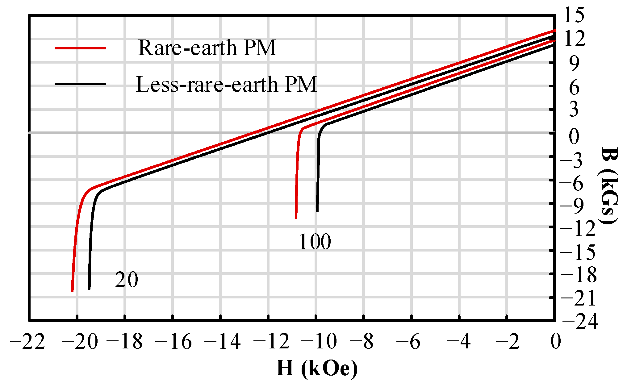
Figure 1. Topology of the proposed structure. (a) Topology. (b) Exploded view.
Energies 18 03051 g001
Figure 2. B-H curves of two models at 20 °C and 100 °C.
Energies 18 03051 g002
Figure 3. Parameterized model of HLEPM machine.
Energies 18 03051 g003
Figure 4. Multi-objective optimization results.
Energies 18 03051 g004
Figure 5. Topologies of the two machines for comparison. (a) HLEPM machine. (b) Conventional PMSM.
Energies 18 03051 g005
Figure 6. No-load air-gap flux density waveforms. (a) Waveforms. (b) Harmonic spectra.
Energies 18 03051 g006
Figure 7. Back electromotive force. (a) Waveforms. (b) Harmonic spectra.
Energies 18 03051 g007
Figure 8. Average torque versus current angle. (a) Total torque. (b) Torque component.
Energies 18 03051 g008
Figure 9. Steady-state-torque waveforms @4500 rpm.
Energies 18 03051 g009
Figure 10. Copper loss distribution. (a) HLEPM machine. (b) Conventional PMSM.
Energies 18 03051 g010
Figure 11. Iron loss distribution. (a) HLEPM machine. (b) Conventional PMSM.
Energies 18 03051 g011
Figure 12. Efficiency maps. (a) HLEPM machine. (b) Conventional PMSM.
Energies 18 03051 g012
Figure 13. Demagnetization rate with varying magnetic bridge thicknesses.
Energies 18 03051 g013
Figure 14. PM demagnetization. (a) HLEPM machine. (b) Conventional PMSM.
Energies 18 03051 g014
Figure 15. Magnetic field distribution. (a) HLEPM machine. (b) Conventional PMSM.
Energies 18 03051 g015
Figure 16. Torque variation under ASC operating condition.
Energies 18 03051 g016
Figure 17. ASC current component. (a) HLEPM machine. (b) Conventional PMSM.
Energies 18 03051 g017
Figure 18. Machine prototype. (a) Rotor. (b) Stator.
Energies 18 03051 g018
Figure 19. FE-predicted and tested no-load line–line voltage waveforms.
Energies 18 03051 g019
Figure 20. External characteristic curve.
Energies 18 03051 g020
Table 1. Material usage of HLEPM machine.
MaterialsBrandCostPercentage of DyPercentage of Tb
Rare-earth PMN42UH63–90 USD/kg3–6%0.25%
Less-rare-earth PMN38UH48–70 USD/kg1.2–3.5%1%
Sator/Rotor core25SW13008–20 USD/kg//
Table 2. Main specifications and dimensions of the proposed HLEPM machine.
ItemUnitValue
Sator outer diametermm210
Rotor outer diametermm138
Air gap lengthmm1
Maximum speedr/min18,000
Maximum efficiency%≥94
DC bus voltageV360
Maximum currentArms630
Number of turns/5
Parallel branches/3
Table 3. Optimization objectives and weights.
ObjectiveValueWeights
TorqueMaximum0.8
Torque rippleMinimum0.6
Iron lossMinimum1
Table 4. Optimization parameter ranges.
ParameterUnitRange
Hpmmm4.5~6.5
FB1-1mm1~3
FB2-1mm1.5~4
FB2-2mm2~4
Lpm1-romm4~12
Lpm2-rimm14~18
Rpm2mm24~28
LBRmm65~67
PM1-2mm5~9
Table 5. Cost of two machines.
ParameterHLEPMConventional PMSM
Winding cost (USD)66.2
Silicon steel cost (USD)63.8
PM weight (kg)0.84(V-shaped)/1.85(arc-shaped)2.65
PM cost (USD)139.2166.95
Total cost (USD)269.2296.95
Relative cost (%)90.7100
Table 6. Loss at the speed of 4500 rpm and rated torque.
Machine TopologyCopper Loss (W)Iron Loss (W)
HLEPM14,000346
Conventional PMSM14,000360
Table 7. The maximum efficiency and maximum power values at the speed of 4500 rpm.
Machine TopologyMaximum Efficiency (%)Maximum Power (kW)
HLEPM97.94218
Conventional PMSM97.95213
Table 8. High-efficiency improvement range and ratio of the proposed machine.
Efficiency (%)Speed Range (rpm)Increase Ratio (%)
9510,600~13,80030
9413,500~18,00033
Table 9. Demagnetization rate under different magnetic bridge thicknesses.
ItemValue
Magnetic bridge (mm)43.532.521.5
Demagnetization rate (%)0.760.931.221.471.792.18
Table 10. Demagnetization rates exceeding 5% and torque reduction rate.
Machine TopologyDemagnetization Rates Exceeding 5% (%)Torque Reduction Rate (%)
HLEPM1.340.19
Conventional PMSM2.280.32
Table 11. Key performance characteristics between FE-predicted and experimental measurements.
ItemFE-PredictedExperimentError
Line-line voltage166.6 V165.4 V0.72%
Maximum power218 kW204.5 kW6.19%
Maximum efficiency97.94%97.11%0.83%
Disclaimer/Publisher’s Note: The statements, opinions and data contained in all publications are solely those of the individual author(s) and contributor(s) and not of MDPI and/or the editor(s). MDPI and/or the editor(s) disclaim responsibility for any injury to people or property resulting from any ideas, methods, instructions or products referred to in the content.

