
Li-Ion Battery Cooling and Heating System with Loop Thermosyphon for Electric Vehicles


Abstract
1. Introduction
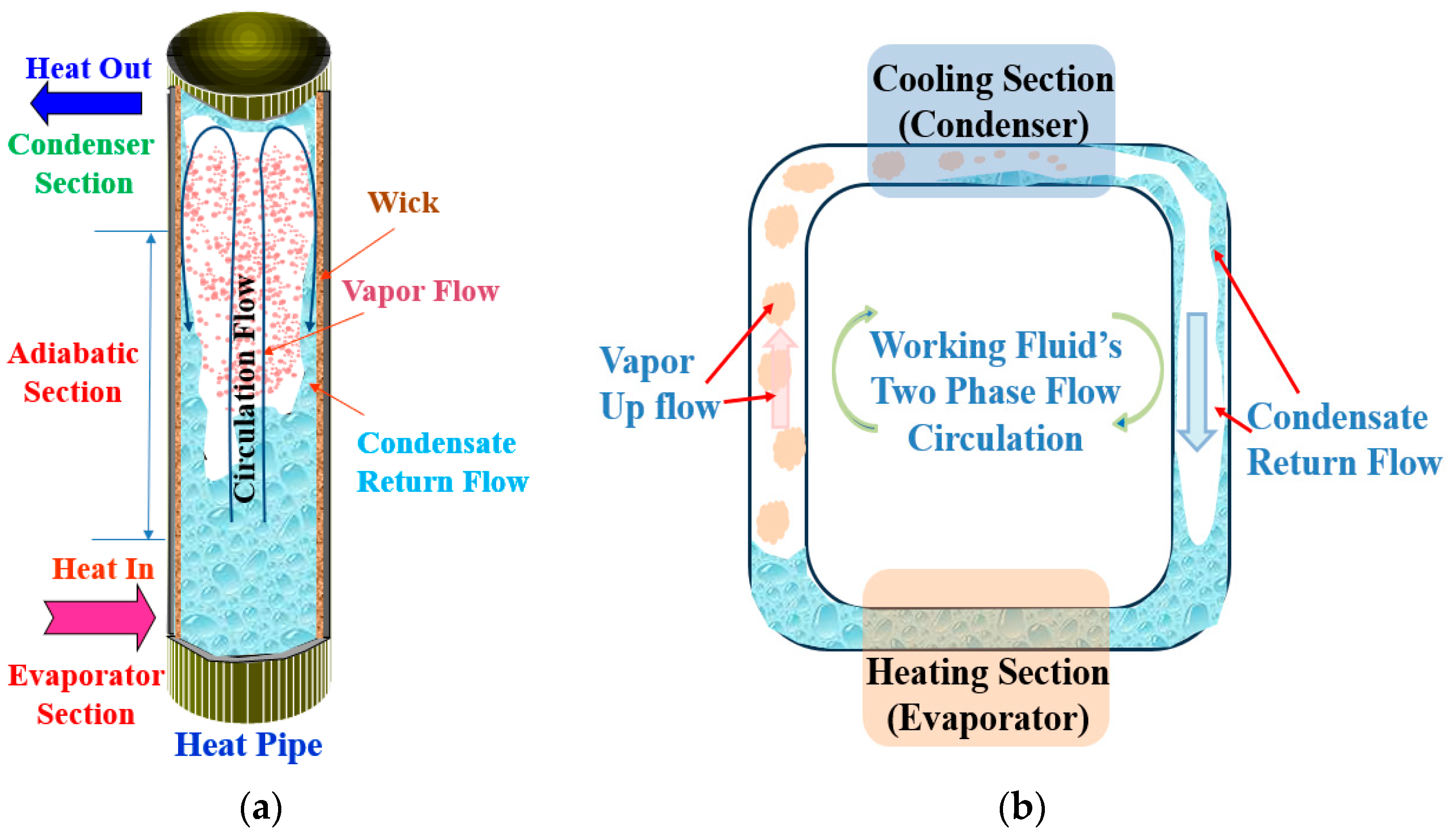
1.1. The Principle of Heat Pipes
1.2. Heat Pipes in Battery Thermal Management Systems (BTMS)
1.3. Hybrid Systems and Emerging Technologies
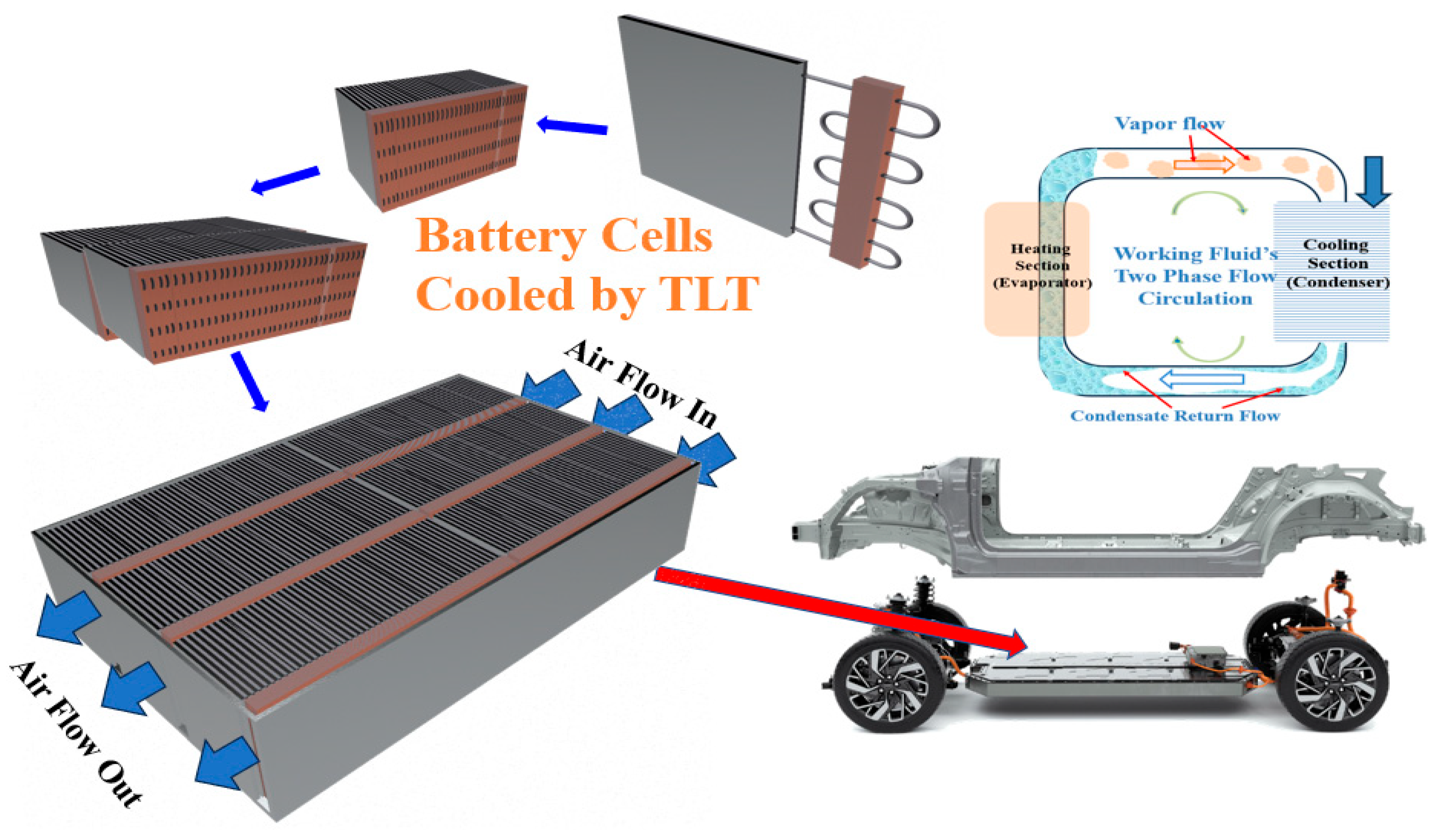
1.4. Innovative Applications: Two-Phase Loop Thermosyphons
1.5. Research Gaps and Current Study
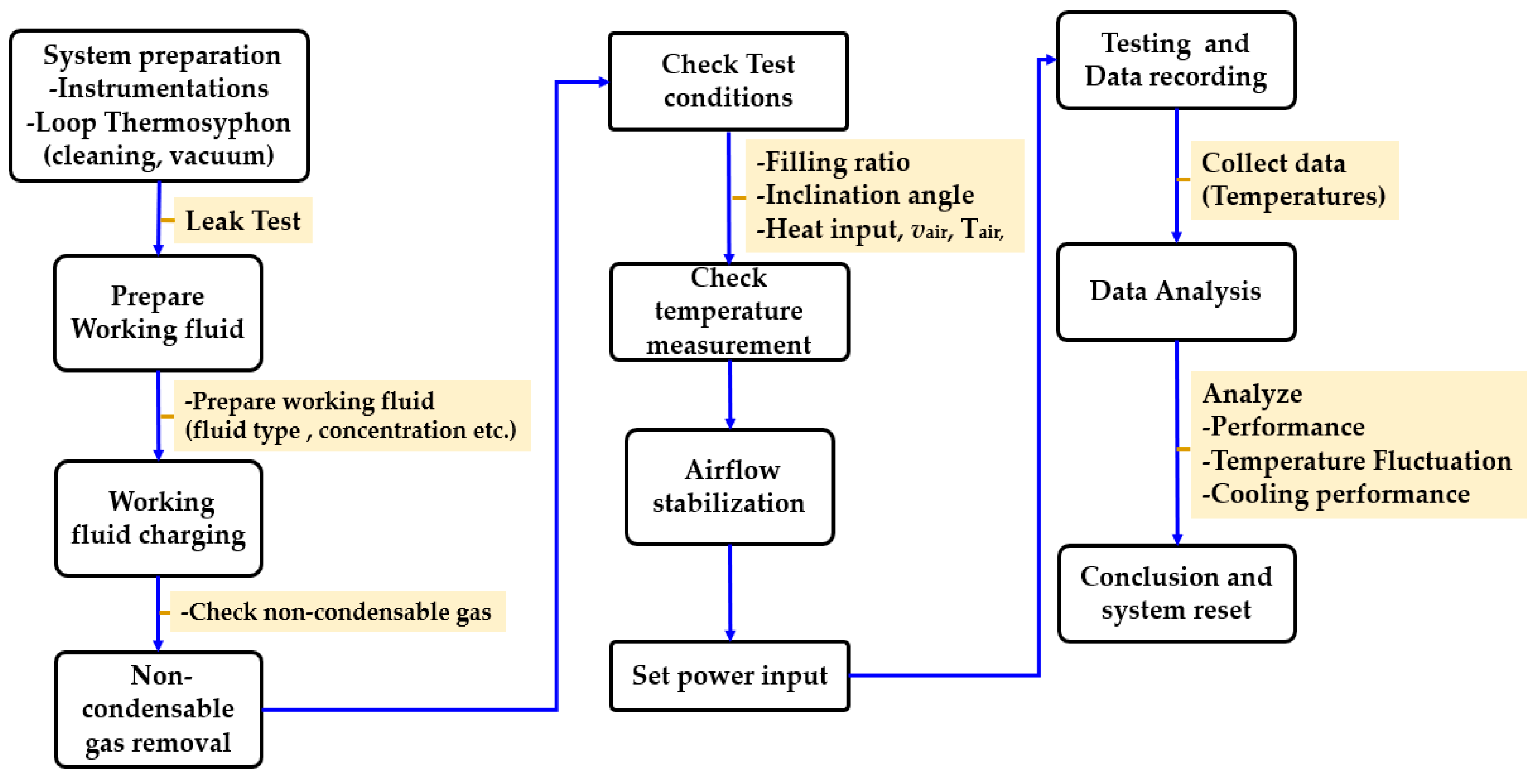
2. Experimental
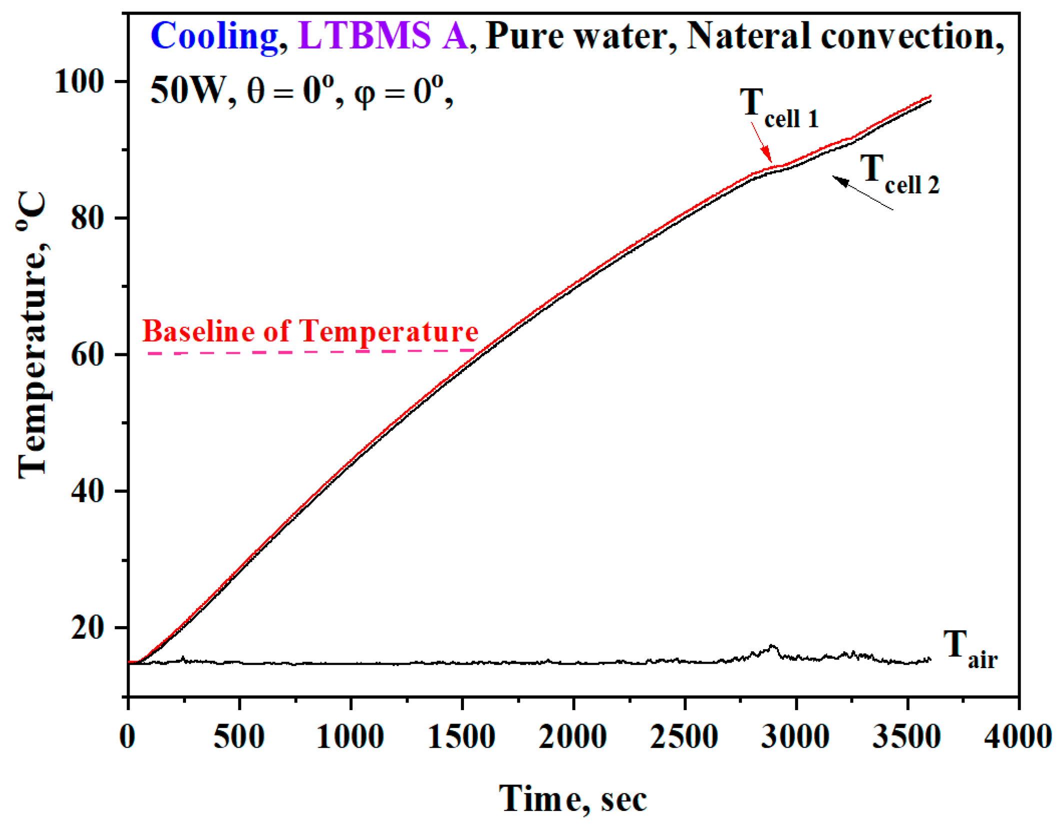
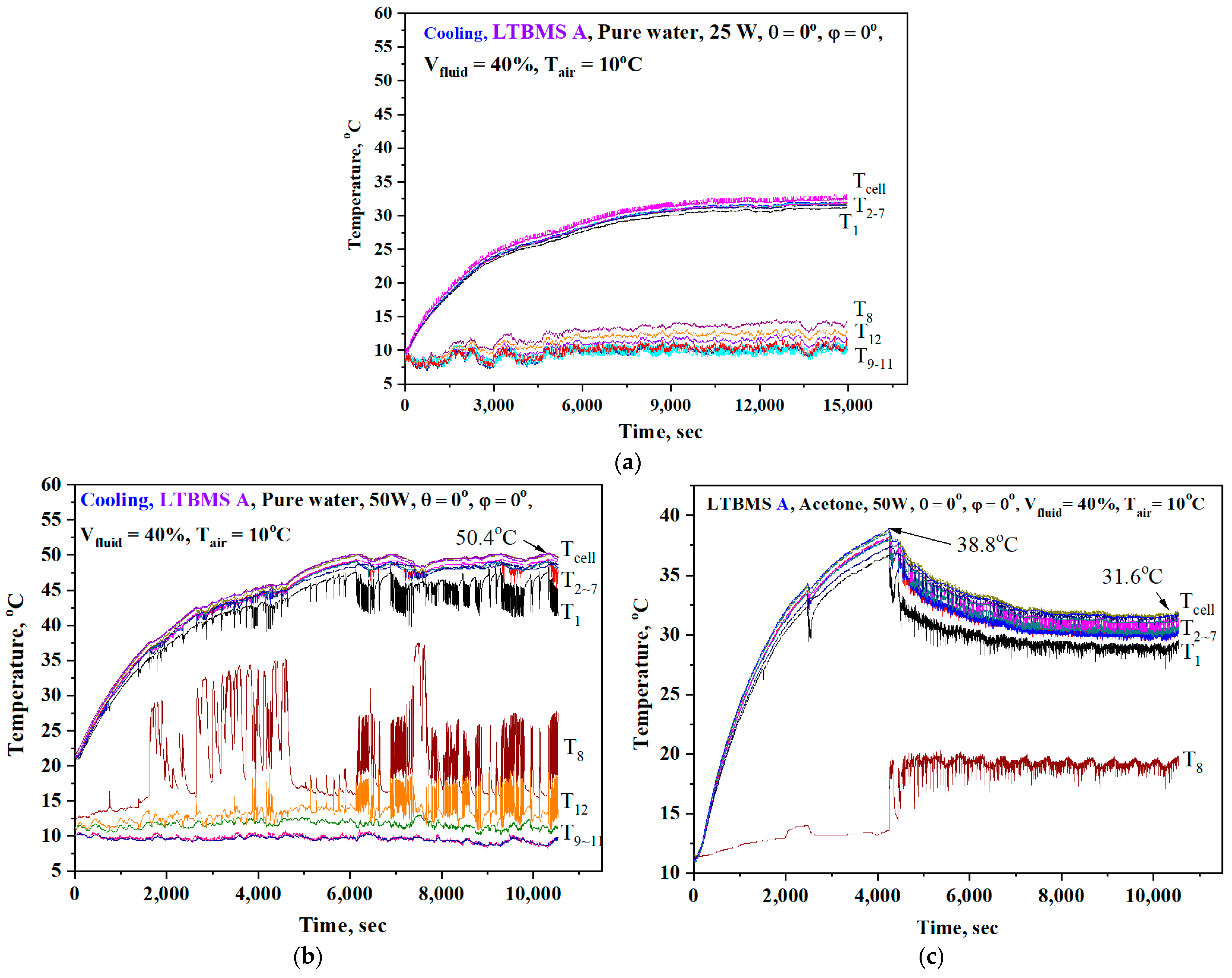
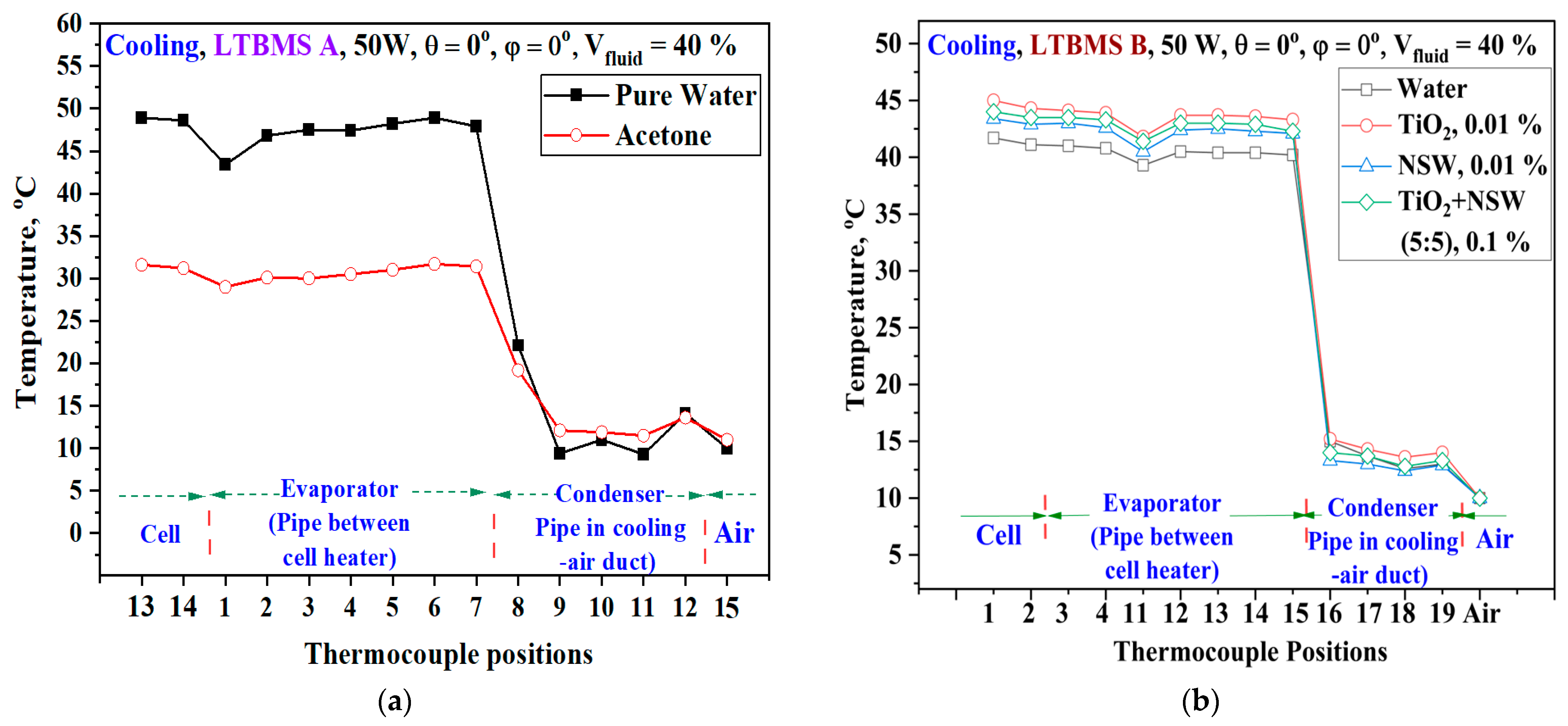
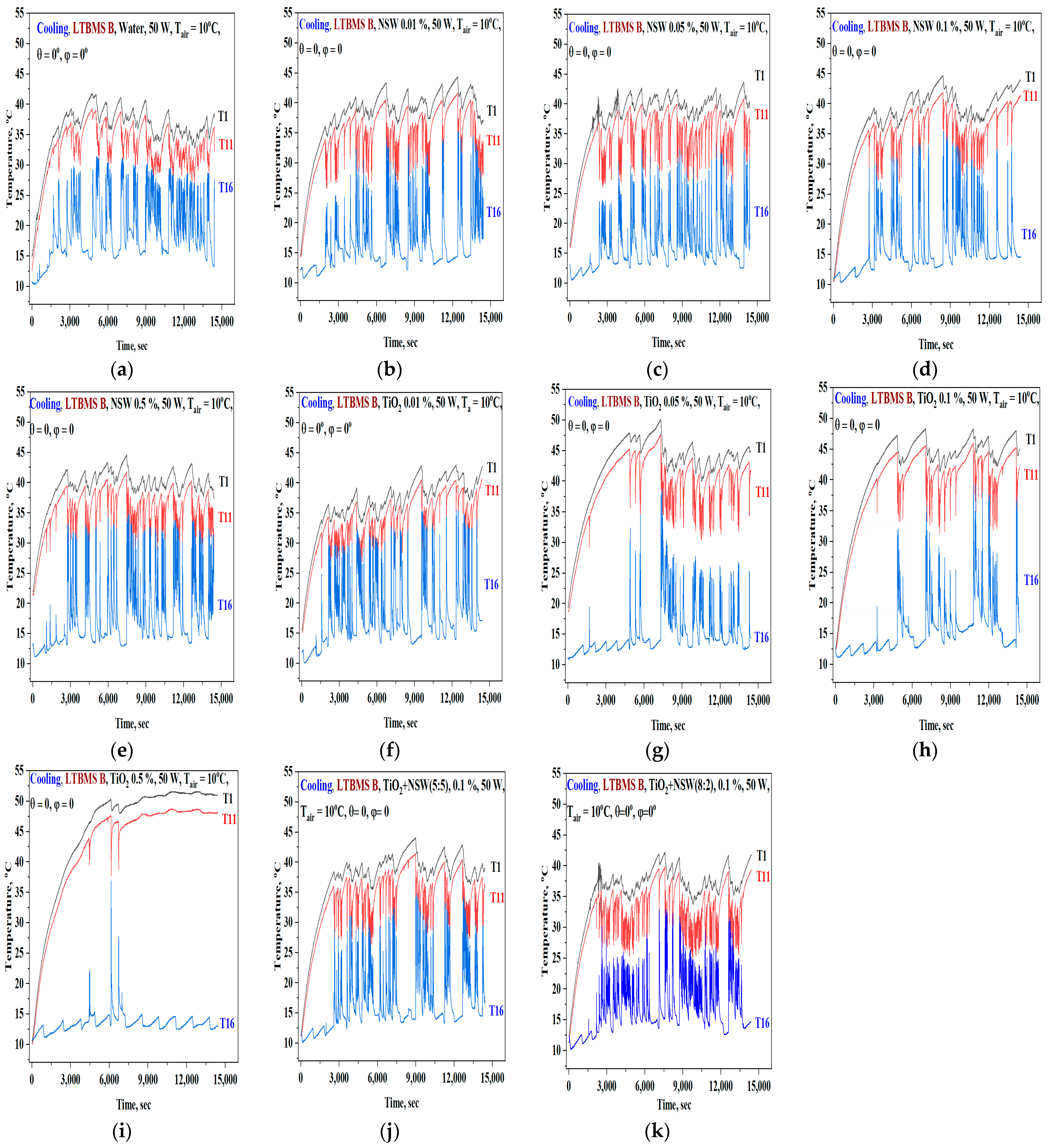
3. Result and Discussion
Battery Cooling Statement
4. Conclusions
Author Contributions
Funding
Institutional Review Board Statement
Informed Consent Statement
Data Availability Statement
Conflicts of Interest
Nomenclature
| LTBMS | Loop thermosyphon battery thermal management system |
| NSW | Nano silver water nanofluid |
| T | Static temperature, °C |
| V | Volume, m3 |
| Greek | |
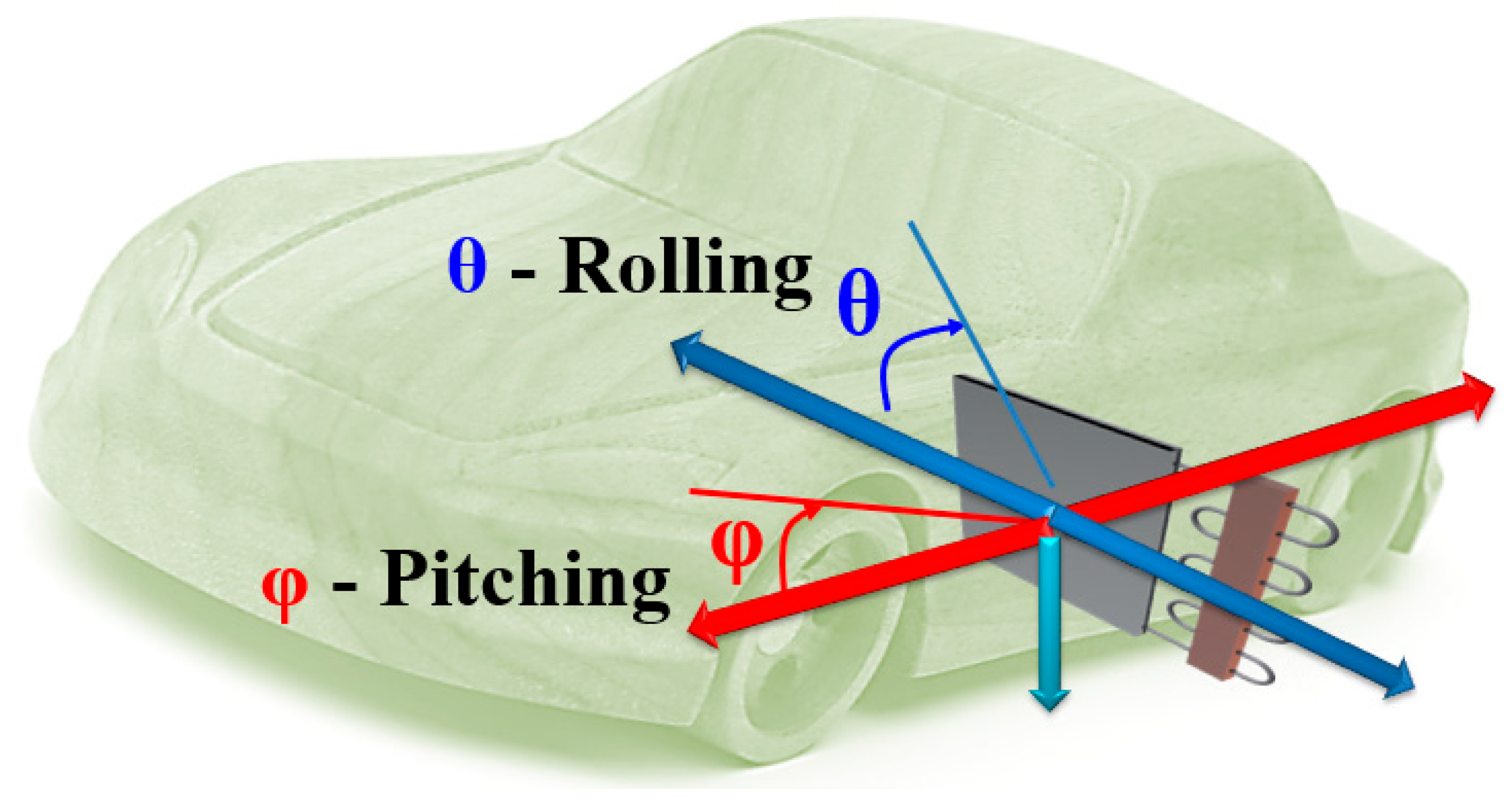
| θ | Rolling angle, degree |
| φ | Pitching angle, degree |
| Subscripts | |
| air | Air |
| Fluid | Working fluid |
References
- Feng, X.; Ren, D.; He, X.; Ouyang, M. Mitigating thermal runaway of lithium-ion batteries. Joule 2020, 4, 743–770. [Google Scholar] [CrossRef]
- Chen, L.; Fan, X.; Hu, E.; Ji, X.; Chen, J.; Hou, S.; Deng, T.; Li, J.; Su, D.; Yang, X.; et al. Achieving high energy density through increasing the output voltage: A highly reversible 5.3 V battery. Chem 2019, 5, 896–912. [Google Scholar] [CrossRef]
- Sun, X.; Yan, C.; Chen, Y.; Si, W.; Deng, J.; Oswald, S.; Liu, L.; Schmidt, O.G. Three-dimensionally “curved” NiO nanomembranes as ultrahigh rate capability anodes for Li-ion batteries with long cycle lifetimes. Adv. Energy Mater. 2014, 4, 1300912. [Google Scholar] [CrossRef]
- Zhao, R.; Liu, J.; Gu, J.; Zhang, Q. The effects of electrode thickness on the electrochemical and thermal characteristics of lithium-ion battery. Appl. Energy 2015, 139, 220–229. [Google Scholar] [CrossRef]
- Chen, K.; Hou, J.; Song, M.; Wang, S.; Wu, W.; Zhang, Y. Design of battery thermal management system based on phase change material and heat pipe. Appl. Therm. Eng. 2021, 188, 116665. [Google Scholar] [CrossRef]
- Rao, Z.; Wang, Q.; Huang, C.; Liu, X. Investigation of the thermal performance of phase change material/mini-channel coupled battery thermal management system. Appl. Energy 2016, 164, 659–669. [Google Scholar] [CrossRef]
- Behi, H.; Karimi, D.; Jaguemont, J.; Ghanbarpour, M.; Berecibar, M. Heat pipe air-cooled thermal management system for lithium-ion batteries: High power applications. Appl. Therm. Eng. 2021, 183, 116240. [Google Scholar] [CrossRef]
- Guo, P.; Xu, Q.; Yue, Y.; Ma, F.; He, Z.; Luo, A.; Guerrero, J.M. Analysis and Control of Modular Multilevel Converter With Split Energy Storage for Railway Traction Power Conditioner. IEEE Trans. Power Electron. 2020, 35, 1239–1255. [Google Scholar] [CrossRef]
- Chen, J.; Zhao, Y.; Wang, M.; Yang, K.; Ge, Y.; Wang, K.; Lin, H.; Pan, P.; Hu, H.; He, Z.; et al. Multi-Timescale Reward-Based DRL Energy Management for Regenerative Braking Energy Storage System. IEEE Trans. Transp. Electrif. 2025, 11, 7488–7500. [Google Scholar] [CrossRef]
- Zhao, C.; Ju, S.; Xue, Y.; Ren, T.; Ji, Y.; Chen, X. China’s energy transitions for carbon neutrality: Challenges and opportunities. Carbon Neutrality 2022, 1, 7. [Google Scholar] [CrossRef]
- Xu, B.; Lee, J.; Kwon, D.; Kong, L.; Pecht, M. Mitigation strategies for Li-ion battery thermal runaway: A review. Renew. Sustain. Energy Rev. 2021, 150, 111437. [Google Scholar] [CrossRef]
- Liu, F.; Lan, F.; Chen, J. Dynamic thermal characteristics of heat pipe via segmented thermal resistance model for electric vehicle battery cooling. J. Power Sources 2016, 321, 57–70. [Google Scholar] [CrossRef]
- Sun, H.; Dixon, R. Development of cooling strategy for an air-cooled lithium-ion battery pack. J. Power Sources 2014, 272, 404–414. [Google Scholar] [CrossRef]
- Oh, I.-T.; Lee, J.-S.; Han, J.-S.; Lee, S.-W.; Kim, S.-J.; Rhi, S.-H. Li-ion battery immersed heat pipe cooling technology for electric vehicles. Electronics 2023, 12, 4931. [Google Scholar] [CrossRef]
- Kim, S.-J.; Lee, J.-S.; Rhi, S.-H. Heat Pipe Embedded Battery Cooling System for Future Electric Vehicle. Batteries 2025, 11, 164. [Google Scholar] [CrossRef]
- Chi, R.-G.; Chung, W.-S.; Rhi, S.-H. Thermal characteristics of an oscillating heat pipe cooling system for electric vehicle Li-ion batteries. Energies 2018, 11, 655. [Google Scholar] [CrossRef]
- Chi, R.-G.; Rhi, S.-H. Oscillating heat pipe cooling system of electric vehicle’s Li-ion batteries with direct contact bottom cooling mode. Energies 2019, 12, 1698. [Google Scholar] [CrossRef]
- Chung, W.-S.; Lee, J.-S.; Rhi, S.-H. Thermal management system using pulsating heat pipe of cylindrical battery cell. J. Mech. Sci. Technol. 2023, 37, 6711–6725. [Google Scholar] [CrossRef]
- Lee, J.-S.; Kim, S.-J.; Han, W.-S.; Rhi, S.-H. Anti-Gravity 3D Pulsating Heat Pipe for Cooling Electric Vehicle Batteries. Energies 2024, 17, 2283. [Google Scholar] [CrossRef]
- Lv, Y.; Yang, X.; Li, X.; Zhang, G.; Wang, Z. Experimental study on a novel battery thermal management technology based on low-density polyethylene-enhanced composite phase change materials coupled with low fins. Appl. Energy 2016, 178, 376–382. [Google Scholar] [CrossRef]
- Nazir, H.; Batool, M.; Osorio, F.J.B.; Xu, X.; Phelan, P.; Inamuddin. Recent developments in phase change materials for energy storage applications: A review. Int. J. Heat Mass Transf. 2019, 129, 491–523. [Google Scholar] [CrossRef]
- Fang, M.; Zhou, J.; Fei, H.; Yang, K.; He, R. Porous-material-based composite phase change materials for a lithium-ion battery thermal management system. Energy Fuels 2022, 36, 4153–4173. [Google Scholar] [CrossRef]
- He, F.; Li, X.; Ma, L. Combined experimental and numerical study of thermal management of battery module consisting of multiple Li-ion cells. Int. J. Heat Mass Transf. 2014, 72, 622–629. [Google Scholar] [CrossRef]
- Liu, K.; Liu, Y.; Lin, D.; Pei, A.; Cui, Y. Materials for lithium-ion battery safety. Sci. Adv. 2018, 4, eaas9820. [Google Scholar] [CrossRef] [PubMed]
- Nicholls, R. Lithium-Ion 18650 Cylindrical Battery Thermal Management: Multi-Level CFD Simulations Utilising Phase Change Materials for Enhanced Performance. Ph.D. Thesis, University of Staffordshire, Stoke-on-Trent, UK, 2024. Available online: https://eprints.staffs.ac.uk/id/eprint/8505 (accessed on 18 January 2025).
- Wang, F.; Cao, J.; Ling, Z.; Zhang, Z.; Fang, X. Experimental and simulative investigations on a phase change material nano-emulsion-based liquid cooling thermal management system for a lithium-ion battery pack. Energy 2020, 207, 118215. [Google Scholar] [CrossRef]
- Jang, D.S.; Ham, S.H.; Kim, J.; Kim, Y. Thermal and aging performance characteristics of pouch-type lithium-ion battery using heat pipes under nonuniform heating conditions. Appl. Therm. Eng. 2024, 236, 121891. [Google Scholar] [CrossRef]
- Kong, F.; Yu, F.; Lu, W.; Yuan, Z.; Qian, B. An organic/inorganic synergistic electrolysis for overcharge protection of electric vehicle batteries. Ind. Eng. Chem. Res. 2019, 58, 1787–1793. [Google Scholar] [CrossRef]
- Goodenough, J.B.; Kim, Y. Challenges for rechargeable Li batteries. Chem. Mater. 2010, 22, 587–603. [Google Scholar] [CrossRef]
- Hu, M.; Pang, X.; Zhou, Z. Recent progress in high-voltage lithium-ion batteries. J. Power Sources 2013, 237, 229–242. [Google Scholar] [CrossRef]
- Yang, C.-P.; Yin, Y.-X.; Zhang, S.-F.; Li, N.-W.; Guo, Y.-G. Accommodating lithium into 3D current collectors with a submicron skeleton towards long-life lithium metal anodes. Nat. Commun. 2015, 6, 8058. [Google Scholar] [CrossRef]
- Ghorabaee, H.; Sarmasti Emami, M.R.; Moosakazemi, F.; Karimi, N.; Cheraghian, G.; Afrand, M. The Use of Nanofluids in Thermosyphon Heat Pipe: A Comprehensive Review. Powder Technol. 2021, 394, 785–806. [Google Scholar] [CrossRef]
- Akbarzadeh, M.; Kalogiannis, T.; Jaguemont, J.; Jin, L.; Karimi, D.; Beheshti, H.; Van Mierlo, J.; Berecibar, M. A Comparative Study between Air Cooling and Liquid Cooling Thermal Management Systems for a High-Energy Lithium-Ion Battery Module. Appl. Therm. Eng. 2021, 11, 117503. [Google Scholar] [CrossRef]
- Garud, K.S.; Tai, L.D.; Hwang, S.-G.; Nguyen, N.-H.; Lee, M.-Y. A Review of Advanced Cooling Strategies for Battery Thermal Management Systems in Electric Vehicles. Symmetry 2023, 15, 1322. [Google Scholar] [CrossRef]
- Choi, H.; Lee, H.; Han, U.; Jung, J.; Lee, H. Comparative Evaluation of Liquid Cooling-Based Battery Thermal Management Systems: Fin Cooling, PCM Cooling, and Intercell Cooling. Int. J. Energy Res. 2024, 2024, 5395508. [Google Scholar] [CrossRef]
- Wang, C.; Liu, Q.; Wang, Z.; Cheng, X. A Review of Power Battery Cooling Technologies. Renew. Sustain. Energy Rev. 2025, 213, 115494. [Google Scholar] [CrossRef]
- Tai, L.D.; Garud, K.S.; Hwang, S.-G.; Lee, M.-Y. A Review on Advanced Battery Thermal Management Systems for Fast Charging in Electric Vehicles. Batteries 2024, 10, 372. [Google Scholar] [CrossRef]
- Xu, L.; Wang, S.; Xi, L.; Li, Y.; Gao, J. A Review of Thermal Management and Heat Transfer of Lithium-Ion Batteries. Energies 2024, 17, 3873. [Google Scholar] [CrossRef]
- Tang, Y.; Li, T.; Cheng, X. Review of Specific Heat Capacity Determination of Lithium-Ion Battery. Energy Procedia 2019, 158, 4967–4973. [Google Scholar] [CrossRef]
- Droese, D.; Kowal, J. Thermal Characterisation of Automotive-Sized Lithium-Ion Pouch Cells Using Thermal Impedance Spectroscopy. Appl. Sci. 2023, 13, 2870. [Google Scholar] [CrossRef]
- Lee, G. Electro-Thermal Analysis of a Pouch–Type Lithium–Ion Battery with a High Discharge Rate for Urban Air Mobility. Batteries 2023, 9, 476. [Google Scholar] [CrossRef]
- Patil, M.S.; Panchal, S.; Kim, N.; Lee, M.-Y. Cooling Performance Characteristics of 20 Ah Lithium-Ion Pouch Cell with Cold Plates along Both Surfaces. Energies 2018, 11, 2550. [Google Scholar] [CrossRef]
- Franco, A.; Filippeschi, S. Closed loop two-phase thermosyphon of small dimensions: A review of the experimental results. Microgravity Sci. Technol. 2012, 24, 165–179. [Google Scholar] [CrossRef]
- Daraghmeh, H.M.; Sulaiman, M.W.; Yang, K.-S.; Wang, C.-C. Investigation of Separated Two-Phase Thermosiphon Loop for Relieving the Air-Conditioning Loading in Datacenter. Energies 2019, 12, 105. [Google Scholar] [CrossRef]
- Kloczko, S.; Faghri, A. Experimental Investigation on Loop Thermosyphon Thermal Performance with Flow Visualization. Int. J. Heat Mass Transf. 2020, 150, 119312. [Google Scholar] [CrossRef]
- Tong, Z.; Han, Z.; Fang, C.; Wen, X. Two-Phase Thermosyphon Loop with Different Working Fluids Used in Data Centers. Int. J. Heat Mass Transf. 2023, 214, 124393. [Google Scholar] [CrossRef]
- Gillespie, T.D. Fundamentals of Vehicle Dynamics; SAE International: Warrendale, PA, USA, 1992; ISBN 978-1-56091-199-9. [Google Scholar]
- Vidonscky Pinto, R.; Sanzovo Fiorelli, F.A. Review of the Mechanisms Responsible for Heat Transfer Enhancement Using Nanofluids. Appl. Them. Eng. 2016, 108, 720–739. [Google Scholar] [CrossRef]
- Govindasamy, M.; Ezhumalai, M.; Dhairiyasamy, R.; Varshney, D.; Singh, S.; Gabiriel, D. Comprehensive Investigation into the Thermal Performance of Nanofluid-Enhanced Heat Pipes for Advanced Thermal Management Systems. Eng 2025, 6, 55. [Google Scholar] [CrossRef]
- Buschmann, M.H. Nanofluids in thermosyphons and heat pipes: Overview of recent experiments and modelling approaches. Int. J. Therm. Sci. 2013, 72, 1–17. [Google Scholar] [CrossRef]
- Pathak, S.K.; Kumar, R.; Goel, V.; Pandey, A.K.; Tyagi, V.V. Recent advancements in thermal performance of nano-fluids charged heat pipes used for thermal management applications: A comprehensive review. Appl. Therm. Eng. 2022, 216, 119023. [Google Scholar] [CrossRef]
- Wang, X.; Luo, L.; Xiang, J.; Lin, Z.; Shittu, S.; Wang, Z. A comprehensive review on the application of nanofluid in heat pipe based on the machine learning: Theory, application and prediction. Renew. Sustain. Energy Rev. 2021, 150, 111434. [Google Scholar] [CrossRef]
- Mohite, D.; Goyal, A.; Singh, A.; Ansari, M.; Patil, K.; Yadav, P.D.; Patil, M.; Londhe, P.; Patil, K. Improvement of Thermal Performance through Nanofluids in Industrial Applications: A Review on Technical Aspects. Mater. Today Proc. 2024; in press. [Google Scholar] [CrossRef]
- Sarafraz, M.M.; Hormozi, F.; Peyghambarzadeh, S.M. Role of nanofluid fouling on thermal performance of a thermosyphon: Are nanofluids reliable working fluid? Appl. Therm. Eng. 2015, 82, 212–224. [Google Scholar] [CrossRef]
- Sundar, L.S.; Singh, M.K.; Sousa, A.C.M. Enhanced heat transfer and friction factor of MWCNT–Fe3O4/water hybrid nanofluids. Int. Commun. Heat Mass Transf. 2014, 52, 73–83. [Google Scholar] [CrossRef]
- Aydın, Y.; Gürü, M.; Sözen, A. Experimental Investigation on Thermal Performance of Thermosyphon Heat Pipe Using Dolomite/Deionized Water Nanofluid Depending on Nanoparticle Concentration and Surfactant Type. Heat Transf. Res. 2020, 51, 1079–7085. [Google Scholar] [CrossRef]
- Shafahi, M.; Bianco, V.; Vafai, K.; Manca, O. An investigation of the thermal performance of cylindrical heat pipes using nanofluids. Int. J. Heat Mass Transf. 2010, 53, 376–383. [Google Scholar] [CrossRef]
- Kang, S.-W.; Wei, W.-C.; Tsai, S.-H.; Yang, S.-Y. Experimental investigation of silver nano-fluid on heat pipe thermal performance. Appl. Therm. Eng. 2006, 26, 2377–2382. [Google Scholar] [CrossRef]
- Qu, J.; Wu, H.-Y.; Cheng, P. Thermal performance of an oscillating heat pipe with Al2O3–water nanofluids. Int. Commun. Heat Mass Transf. 2010, 37, 111–115. [Google Scholar] [CrossRef]
- Cacua, K.; Buitrago-Sierra, R.; Pabón, E.; Gallego, A.; Zapata, C.; Herrera, B. Nanofluids stability effect on a thermosyphon thermal performance. Int. J. Therm. Sci. 2020, 153, 106347. [Google Scholar] [CrossRef]


| Cooling Method | Tcell Range | Performance | Advantages | Disadvantages |
|---|---|---|---|---|
| Air Cooling [33,34,35,36] | 25–55 °C | Less effective; struggles to maintain <50 °C | Simple; cost-effective | Limited cooling efficiency; higher temperature variations |
| In direct Liquid Cooling [33,35,36,37] | 20~50 °C | Superior heat transfer; maintains uniformity | Efficient for high-performance applications | Higher initial costs; complexity in design |
| Phase Change Material(PCM) [20,23,25,26,34,35,36] | 30~45 °C | Absorbs heat during phase change; stable temps | Passive cooling; energy-efficient | Limited commercial application; still in research phase, various performance depending on PCM |
| Heat Pipe Cooling [14,19,27,36,37,38] | <55 °C | Efficient heat transfer; flexible design | Good for high heat loads | Requires careful integration; can be bulky |
| Hybrid Cooling [34,35,36] | ~38 °C | Combines strengths of multiple methods | Optimized performance; enhanced stability | Complexity in system design and control |
| Direct Liquid Cooling [34,36,37] | <40 °C | Excellent thermal performance; low pressure drop | Direct contact with coolant enhances cooling | Increased system weight; potential for leaks |
| Nanofluid Cooling [36] | <55 °C | Enhanced heat transfer rates | Significant cooling improvements over traditional methods | Still under research; potential cost issues |
| LTBMS A | LTBMS B | |
|---|---|---|
| Battery cell | (100% discharged battery cell + electronic plate heater block) 2ea | |
| 191 × 146 mm | ||
| Fin | 0.5 mm Thick Aluminum fin | |
| 8.9(w) × 191(h) mm | 15(w) × 191(h) mm | |
| 29 ea | 53 ea | |
| Duct | 42(w) × 191(h) mm | 72(w) × 191(h) mm |
| Fan | 120 × 120 mm | 80 × 80 mm (2ea) |
| 2.5 m3/min | ||
| Heater | Constant Temperature heating | Electronic heater block for cell heating mode (4ea) |
| Thermosyphon Pipe | R = 1.588 mm (D1/8 inch) | R = 3.175 mm (D1/4 inch) |
| Division | Working Fluid | Power | θ | ϕ | Tair, °C |
|---|---|---|---|---|---|
| LTBMS A Cooling Mode | Pure water | 50 W | 0° | 0° | 10 |
| 25 W | 300~60° | 0° | |||
| 0° | 0~60° | ||||
| Acetone | 50 W | 0° | 0° | ||
| 25 W | 300~60° | 0° | |||
| 0° | 0~60° | ||||
| LTBMS A Heating Mode | Acetone | 50 °C | 0° | 0° | −10 |
| 55 °C | 0 | ||||
| 60 °C | 10 | ||||
| 65 °C | 20 | ||||
| LTBMS B Cooling Mode | Pure water | 50 W | 300~60° | 0° | 10 |
| 0° | 0~60° | ||||
| TiO2 nanofluid (0.01%, 0.05%, 0.1%, 0.5%) NSW (nano silver water) (0.01%, 0.05%, 0.1%, 0.5%) TiO2 + NSW Hybrid nanfluid (5:5, 8:2 0.1%) | 300~60° | 0° | |||
| 0° | 0~60° | ||||
| LTBMS B Heating Mode | Pure water | 100 W | 0° | 0° | −10~10 |
| TiO2 nanofluid (0.01%, 0.05%, 0.1%, 0.5%) | −10~10 | ||||
| TiO2 + NSW Hybrid nanfluid (5:5, 0.1%) | −10~10 |
Disclaimer/Publisher’s Note: The statements, opinions and data contained in all publications are solely those of the individual author(s) and contributor(s) and not of MDPI and/or the editor(s). MDPI and/or the editor(s) disclaim responsibility for any injury to people or property resulting from any ideas, methods, instructions or products referred to in the content. |
© 2025 by the authors. Licensee MDPI, Basel, Switzerland. This article is an open access article distributed under the terms and conditions of the Creative Commons Attribution (CC BY) license (https://creativecommons.org/licenses/by/4.0/).
Share and Cite
Jang, J.-C.; Lim, T.-K.; Lee, J.-S.; Rhi, S.-H. Li-Ion Battery Cooling and Heating System with Loop Thermosyphon for Electric Vehicles. Energies 2025, 18, 3687. https://doi.org/10.3390/en18143687
Jang J-C, Lim T-K, Lee J-S, Rhi S-H. Li-Ion Battery Cooling and Heating System with Loop Thermosyphon for Electric Vehicles. Energies. 2025; 18(14):3687. https://doi.org/10.3390/en18143687
Chicago/Turabian StyleJang, Ju-Chan, Taek-Kyu Lim, Ji-Su Lee, and Seok-Ho Rhi. 2025. "Li-Ion Battery Cooling and Heating System with Loop Thermosyphon for Electric Vehicles" Energies 18, no. 14: 3687. https://doi.org/10.3390/en18143687
APA StyleJang, J.-C., Lim, T.-K., Lee, J.-S., & Rhi, S.-H. (2025). Li-Ion Battery Cooling and Heating System with Loop Thermosyphon for Electric Vehicles. Energies, 18(14), 3687. https://doi.org/10.3390/en18143687