Abstract
As a pivotal technology and infrastructure component for modern power systems, energy storage has experienced significant advancement in recent years. A fundamental prerequisite for designing future energy storage facilities lies in the systematic evaluation of energy conversion capabilities across diverse storage technologies. This study conducted a comparative analysis between pumped hydroelectric storage (PHS) and compressed air energy storage (CAES), defining the concepts of height exergy and temperature exergy. Height exergy is the maximum work capacity of a liquid due to height differences, while temperature exergy is the maximum work capacity of a gas due to temperature differences. The temperature exergy represents innovation in thermodynamic analysis; it is derived from internal exergy and proven through the Maxwell relation and the decoupling method of internal exergy, offering a more efficient method for calculating energy storage capacity in CAES systems. Mathematical models of height exergy and temperature exergy were established based on their respective forms. A unified calculation formula was derived, and their respective characteristics were analyzed. In order to show the meaning of temperature exergy more clearly and intuitively, a height exergy model of temperature exergy was established through analogy analysis, and it was concluded that the shape of the reservoir was a cone when comparing water volume to heat quantity, intuitively showing that the cold source had a higher energy storage density than the heat source. Finally, a typical hybrid PHS–CAES system was proposed, and a mathematical model was established and verified in specific cases based on height exergy and temperature exergy. It was demonstrated that when the polytropic exponent n = 1.2, the theoretical loss accounted for the largest proportion, which was 2.06%.
1. Introduction
The current power system has gradually transitioned to a new stage characterized by a high proportion of new energy and a high proportion of power electronic equipment. Especially in China, driven by the strategic development goals of carbon peaking and carbon neutrality, the installed capacities of wind power and photovoltaic generation have reached approximately 520 GW and 880 GW, respectively, with their combined share in total electricity generation accounting for 35% by the end of 2024 [1,2]. With the continuous increase in the proportion of new energy sources, such as wind and solar, with intermittent and fluctuating characteristics, traditional controllable synchronous machine power sources are being gradually replaced, resulting in the gradual weakening of the power system’s voltage and frequency flexibility in adjustment and support capabilities. The equivalent inertia level of the system continues to decline, and the characteristics of low inertia, low damping, and weak voltage are evident. The operational stability, safety, and reliability of the power system will face significant challenges [3,4,5].
Due to the energy time shift and bidirectional regulation characteristics of energy storage systems, applying energy storage in power systems is an important technical means to improve the operational flexibility of power systems and the new energy absorption capacity [6,7]. The application of large-scale energy storage technology in the new power system not only plays an important role in peak shaving and frequency modulation, inertia, and auxiliary services but also provides an important means for improving the power supply capability of the new power system and ensuring the real-time balance of electric power [8,9].
In large-scale energy storage technologies, pumped hydroelectric storage (PHS) is the most mature technology, which can be divided into ground-based PHS and ocean-based PHS systems according to the location of the reservoir. In addition, there are also new energy storage technologies, such as electrochemical energy storage, compressed air energy storage (CAES), and gravitational energy storage [10]. Various energy storage technologies have their own technical characteristics and advantages in application scenarios, system capacity, response time, system safety, charge and discharge times, and service life, and they play different important roles in different operation scenarios of the new power system [10]. Among them, traditional PHS is currently the most widely used large-scale energy storage technology in power systems [11], but its large-scale development is limited by the geographical conditions of water resources, and it is also difficult to meet the diversified application scenario requirements of the new power system in terms of power response time [12]. Compressed air energy storage (CAES), one of the most promising large-scale energy storage technologies, has higher flexibility and response speed than PHS. However, the efficiency of commercially operated systems is generally 40–60%, and the coupling of gas storage and heat storage problems caused by the adiabatic compression process is complex. Due to the lack of intuitive models for the loss of available energy caused by temperature changes, it is not convenient to calculate energy storage capacity and conduct efficiency analysis [13].
Above all, the basis for designing the energy storage capacity of energy storage stations in the future is to better understand and analyze various types of energy storage, especially those involving heat sources and cold sources, and to quickly calculate their work capacity. In engineering thermodynamics, exergy serves as a critical parameter for quantifying available energy, playing a pivotal role in system efficiency evaluation and loss localization [14]. Within the thermodynamic exergy framework, three principal forms are recognized: heat exergy (a process-dependent quantity employed to quantify the available energy during heat transfer processes), enthalpy exergy (a process-independent state quantity representing the available energy of flowing working fluids, commonly applied in energy efficiency assessments of compressors and expanders), and internal energy exergy (a state quantity characterizing the maximum available energy of working fluids in closed systems, primarily used to describe energy storage potential in thermal reservoirs or pressurized air chambers) [15]. Current exergy-based analyses of compressed air energy storage systems predominantly employ enthalpy exergy, as they focus on technical work losses of flowing working fluids in open systems. The derived pressure exergy and thermal exergy intrinsically correlate with pressure and temperature changes during fluid flow [16]. However, when characterizing CAES storage capacity, internal energy exergy provides a more pertinent analytical framework. Consequently, quantifying how temperature variations in an air storage chamber impact available work demands a novel thermodynamic parameter, a challenge that remains unaddressed in contemporary research [17,18]. This background has spurred research on and analysis of the physical quantity of temperature exergy. The decoupling calculation makes it simple to analyze the energy storage of complex energy storage systems.
This paper summarizes two types of exergy from multiple energy storage forms, namely height exergy and temperature exergy, which respectively represent the work capacity generated by height differences and temperature differences. By studying their respective characteristics and conducting analogy analysis, the paper reveals the physical meaning and more intuitive interpretation methods of temperature exergy, providing a simplified tool for analyzing the energy storage capacity under complex working conditions. Based on the analogy analysis method, a height exergy model of temperature exergy is established, the shape of the reservoir when using water volume to analogize heat quantity is derived, and the energy storage characteristics of heat sources and cold sources are analyzed. In order to enhance the application value of analogy analysis methods, a typical hybrid pumped hydroelectric storage and compressed air energy storage (PHS–CAES) system is proposed, and a mathematical model of it is established and verified for specific cases. It is concluded that the shape of the reservoir is conical with a narrow top and wide bottom, showing that the cold source has a higher energy density, which can reduce the storage volume under the same capacity demand of energy storage, thereby reducing the investment cost of the system in energy-related equipment. In a typical PHS–CAES system, the mathematical model and work process are thoroughly analyzed, verifying the correctness of the temperature exergy model and analyzing the operating conditions where the maximum loss occurs.
In this paper, Section 2 describes the concept and forms of height exergy, while Section 3 describes the concept and forms of temperature exergy. The analogy analysis is shown in Section 4. A typical hybrid PHS–CAES system is studied using a height exergy and temperature exergy model in Section 5. Finally, the conclusions are summarized in Section 6.
2. Height Exergy
2.1. Concept
Height exergy, also known as height potential energy, refers to the work capacity that an object has due to its height difference from a reference plane. It is the main form of stored energy in a PHS system. This section takes a PHS system as an example to analyze the height exergy possessed by objects.
2.2. Forms of Height Exergy
PHS systems have high efficiency in energy conversion, with a round-trip efficiency ranging from 70% to 75%. In Brazil, combining PHS with stepped hydropower dams can increase the overall energy storage efficiency to 90% [19]. In general, a significant height difference between the upper and lower reservoirs is usually required to create sufficient height potential energy reserves [20]. There are two main forms of expression for the height exergy of water in a PHS, as shown in Figure 1.
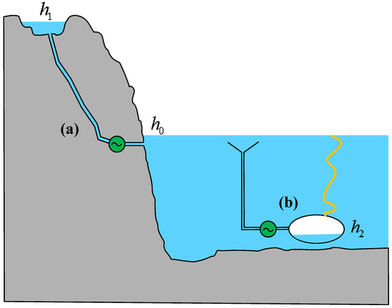
Figure 1.
Two forms of height exergy.
One form is the height exergy possessed due to the reservoir being higher than the reference liquid level (h1 > h0), as shown in Figure 1a. This form is the most common and widely used and is the main form of above-ground PHSs. China has become one of the most active countries in the deployment of PHSs. The rated head of the Xilongchi PHS is 644 m in Shanxi Province, while the rated head of the Tiantai PHS is 724 m, which is the highest in the world and is expected to be put into operation in 2027. The total installed capacity of Tiantai PHS is 1.7 GW, with the largest single unit capacity in the country. In Connecticut, USA, existing reservoirs are used as the foundation for PHSs, and the capacity of the water supply system is evaluated based on the water level time series of the water supply reservoir over 9 years, achieving sustainable integration of renewable energy [21,22].
Another form of height exergy exists due to the reservoir being below the reference water level (h2 < h0), as illustrated in Figure 1b. This configuration represents the primary form of novel ocean-based PHSs. As hydropower development continues to expand, finding suitable locations for construction on land has become increasingly challenging. Additionally, rising costs associated with land acquisition and resettlement further exacerbate these difficulties. Ocean-based PHSs have gained investment interest due to their cost advantages, including the need for only a lower reservoir, the absence of long tunnels connecting upper and lower reservoirs, and the elimination of mountain access infrastructure. Although the initial investment in high-corrosion-resistant materials for seawater-based energy storage systems is relatively high, their extended service life and low maintenance costs contribute to an overall cost advantage over the project lifecycle. Furthermore, in coordinated operation with offshore wind farms, such systems effectively regulate wind power fluctuations, enhance the stability of the power system, and improve the penetration of renewable energy in island grids [23,24]. For low-head island applications, the introduction of wind-powered pumped storage systems (WP-PSSs) can maximize energy efficiency [25].
2.3. Mathematical Model of Height Exergy
For a given reservoir, its volume V can be expressed as:
where h0 represents the reference water level, which corresponds to the lower reservoir level or sea level; S(h) denotes the cross-sectional area of the reservoir at height h, expressed as a function of h to characterize the reservoir’s shape. From Equation (1), it can be observed that when the reservoir is above the reference level, V > 0, indicating stored water volume, whereas when the reservoir is below the reference level, V < 0, representing the discharged water volume.
Regardless of whether the reservoir is above or below the reference water level, the exergy stored through water storage or discharge can be determined using the corresponding gravitational potential energy formula:
where is the density of water and g is the gravitational acceleration. By integrating Equations (1) and (2), a unified expression for the stored exergy can be derived as:
It can be observed that, since S(h) > 0, the stored exergy remains positive (E > 0) when the reservoir is above the reference water level, and it also remains positive (E > 0) when the reservoir is below the reference water level. This indicates that regardless of whether the stored water volume is above the reference level or the discharged water volume is below it, the reservoir always possesses potential energy. This exergy arises from the height difference between the reservoir and the reference level, which fundamentally enables energy storage in both types of pumped storage power stations. When the reservoir height remains constant at h0, the stored exergy becomes zero (E = 0), meaning it is in equilibrium with the reference level.
When the cross-sectional area of the reservoir remains constant, i.e., S(h) = K, the stored exergy for a reservoir configured either above or below the reference level can be simplified as:
The characteristics of the stored height exergy described by Equation (4) are illustrated in Figure 2. In the figure, the reference level is set to h0 = 100 m. Under different cross-sectional areas, the relationship between the stored height exergy and height exhibits a parabolic distribution.
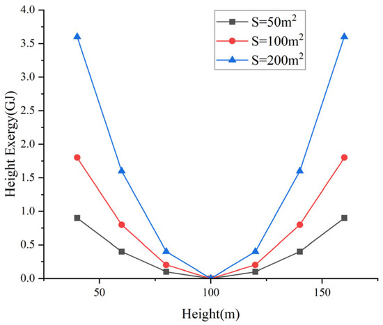
Figure 2.
Characteristic curve of height exergy.
2.4. The Height Exergy of a Constant-Height Model
As a special type of reservoir, a constant-height model maintains a fixed water level H during the energy conversion process, meaning that the minor water level fluctuations during charge/discharge cycles are negligible relative to typical hydraulic head elevations, justifying the steady-height approximation. Taking the Xilongchi PHS system as an example, its rated head is 644 m, the normal water level of the upper reservoir is 1492.5 m, the dead water level is 1467 m, and the head fluctuation ratio is 4.0%, which can be approximated as a constant height body model. In this case, the exergy of the constant-height model is given by:
where V > 0 represents the stored water volume and V < 0 represents the discharged water volume. The constant-height model plays a significant role in the energy conversion calculations of practical pumped storage power stations. When the water level variation in the reservoir is relatively small during operation, the constant-height model can be used for computation. Generally, this model can be used for PHS power stations with large reservoirs or high water heads, but the application of this model is limited for small reservoirs or low water heads due to the large proportion of water head fluctuations. Alternatively, the average height during operation can be substituted as the constant height in Equation (5) to simplify the calculation process. Table 1 shows the water head and energy storage density of five typical PHS systems in China.

Table 1.
Five typical PHS systems in China.
3. Temperature Exergy
3.1. Concept
Temperature exergy represents the ability to perform work due to a temperature difference between a thermal source and a reference temperature, assuming constant volume [26]. It is the energy storage form in the thermal storage chamber of advanced adiabatic compressed air energy storage (AA-CAES). Typically, the reference temperature is chosen as the ambient temperature T0.
Conventional CAES employs adiabatic compression, storing the constant volume of compressed air. However, in ambient conditions, temperature variations in the air storage chamber lead to the dissipation of temperature exergy, which is a key factor contributing to the low efficiency of conventional CAES. In contrast, AA-CAES separates the air storage and thermal storage processes by incorporating a dedicated thermal storage chamber to retain the high-temperature exergy of the compressed air. The concept of temperature exergy was innovatively proposed for the first time, and it plays an important role in locating the efficiency loss of traditional CAES systems and evaluating the thermal storage performance of AA-CAES.
This section analyses the temperature exergy of a given quantity of compressed air, assuming that the volume of compressed air remains constant.
3.2. Forms of Temperature Exergy
In a CAES system, the temperature exergy of air primarily manifests in two forms, as illustrated in Figure 3.
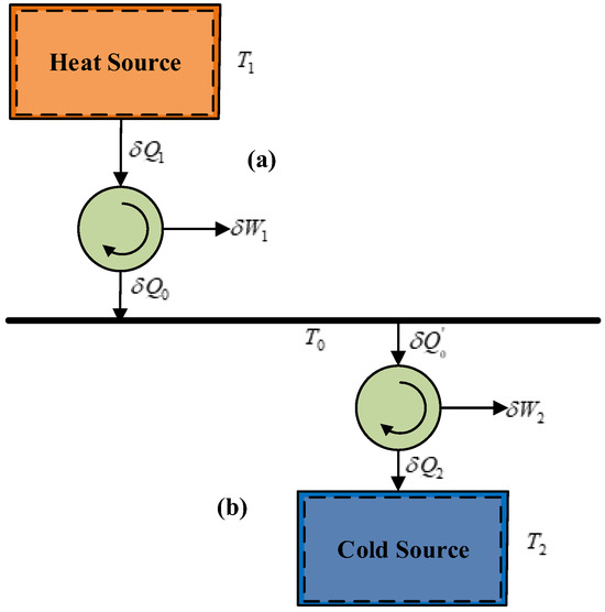
Figure 3.
Two forms of temperature exergy.
One form of temperature exergy arises when the temperature of the gas in the storage chamber is higher than the ambient temperature (T1 > T0), referred to as heat-source temperature exergy, as shown in Figure 3a. This type of gas is typically produced at the end of the compression process. For example, considering adiabatic compression starting from ambient conditions (T0 = 20 °C), the gas temperature reaches 114 °C when the volumetric compression ratio is 2 and 237 °C when the volumetric compression ratio is 4.
Another form of temperature exergy occurs when the gas temperature in the storage chamber is lower than the ambient temperature (T2 < T0), known as cold-source temperature exergy, as shown in Figure 3b. This type of gas is primarily generated at the end of the expansion process. For instance, during adiabatic expansion starting from ambient conditions (T0 = 20 °C), the gas temperature drops to −51 °C when the volumetric expansion ratio is 2 and further decreases to −105 °C when the volumetric expansion ratio is 4.
3.3. Mathematical Model of Temperature Exergy
For a given thermal source, the heat quantity Q can be expressed as:
where T0 is the ambient temperature and CV(T) is the specific heat capacity at constant volume of the thermal source, which is a function of temperature T. From Equation (6), it can be observed that when the temperature of the thermal source is higher than the ambient temperature, Q > 0, indicating heat dissipation from the thermal source. When the temperature of the thermal source is lower than the ambient temperature, Q < 0, indicating heat absorption by the thermal source.
Regardless of whether the thermal source is above or below the ambient temperature, it can perform work through a series of Carnot engines. The maximum work output during the heat absorption and heat dissipation processes of the thermal source is the temperature exergy, as expressed by the following equation:
where (T − T0)/T represents the thermal efficiency of a heat engine. By integrating Equations (6) and (7), a unified expression for temperature exergy can be derived as:
It can be observed that, since CV(T) > 0, when the temperature of the thermal source is higher than the ambient temperature, E > 0, and when the temperature of the thermal source is lower than the ambient temperature, E > 0 still holds. This indicates that both heat sources and cold sources possess temperature exergy. The temperature exergy arises due to the temperature difference between the thermal source and the ambient temperature, which is the fundamental reason for energy storage in the thermal storage or cold storage chambers of a CAES. When the temperature of the thermal source is constant at T0, the temperature exergy becomes zero.
The specific heat capacity at constant volume of the thermal source generally increases with temperature, but the change is small and can usually be treated as a constant. Generally, CV remains relatively constant below 0 °C and only increases by 3 J/kg·K−1 from 0 to 100 °C and 8 J/kg·K−1 from 100 to 200 °C, so it can be approximated as constant within the temperature range of −100 to 250 °C. From Equation (8), it can be concluded that the temperature exergy of the thermal source can be expressed as:
The characteristics of the temperature exergy described by Equation (9) are shown in Figure 4. In the figure, 1 kg of air is analyzed with the condition of T0 = 20 °C, CV = 716.4 J/K. It can be observed that the temperature exergy exhibits a nonlinear relationship with temperature.
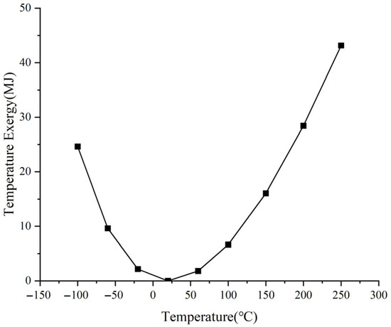
Figure 4.
Characteristic curve of temperature exergy.
It should be noted that temperature exergy and heat exergy are different. Temperature exergy is a state variable, while heat exergy is a process variable. Temperature exergy represents the ability of a heat source to perform external work solely based on temperature while maintaining a constant volume, and its value can be equivalent to the maximum value of heat exergy at ambient temperature. It is derived from the concept of internal energy and will be proven through thermodynamic formulas in Section 3.4.
3.4. Thermodynamics Verification of Temperature Exergy Based on the Decoupling Method of Internal Exergy
Generally, the stored energy in a CAES system is calculated using the internal exergy because the air storage chamber can be treated as a closed system at the end of the compression process [27]. Internal exergy represents the maximum work potential of the working gas within the closed system. Its mathematical expression is:
It can be observed that the internal exergy depends on the system’s internal energy (U), volume (V), and entropy (S), as well as the environmental temperature (T0) and pressure (p0). When the closed system reaches the environmental dead state, it loses the capacity to perform work, meaning its internal energy exergy becomes zero. In all other states, the internal energy exergy is positive. The fundamental state parameters of a closed system are pressure (p), specific volume (v), and temperature (T), all of which are intensive properties and are interdependent. According to the kinetic theory of molecules, temperature (T) characterizes the average kinetic energy of molecular thermal motion, specific volume (v) characterizes molecular density (N), and pressure (p), as a statistical quantity, results from the continuous impulse imparted by molecular collisions with the container walls. Microscopically, pressure is related to the average kinetic energy of molecular thermal motion and molecular density [28]. Consequently, when molecular geometric size is negligible, the microscopic expression of pressure is:
Therefore, from a microscopic perspective, the work potential of a closed system arises from changes in both the average kinetic energy of molecular thermal motion and the molecular density. Macroscopically, specific volume (v) (or density) and temperature (T) are more fundamental state parameters for describing a closed system than pressure (p).
Since the average kinetic energy of molecular thermal motion and molecular density are mutually independent factors influencing work potential, the internal exergy of the closed system can conceptually be decomposed into two parts along these dimensions, based on the temperature (T) and specific volume (v). These components can transform into each other and together constitute the total internal exergy. The following analysis proceeds by decomposing the specific internal energy exergy using the state parameters specific volume (v) and temperature (T).
Starting from the differential form of the specific internal exergy expression [27,29]:
Utilizing the fundamental thermodynamic differential relation du = Tds − pdv, we obtain:
Using the total differential for entropy, , along with the Maxwell relation and , yields:
Since internal exergy is a state variable, its value is path-independent. The above differential can thus be integrated between a given state and the constrained dead state along any convenient path. Choosing a path involving an isochoric step followed by an isothermal step gives the specific internal energy exergy at any state:
Equation (15) demonstrates that the internal exergy of any working gas can be decomposed into two distinct parts. The former part arises from the temperature difference at constant specific volume. It represents the work potential due solely to the temperature of the working gas relative to the environment. The expression of temperature exergy shown in Equation (16) is consistent with Equation (8) in Section 3.3, which also confirms the correctness of the definition.
The latter part in Equation (15) is the work capacity caused by the imbalance of the specific volume or density of the working gas at ambient temperature, which is also applied in the subsequent case analysis section.
3.5. The Temperature Exergy of a Constant-Temperature Model
A constant-temperature source, a special type of thermal source, maintains a constant temperature T throughout the work extraction process, which implies that the specific heat capacity at constant volume, CV, tends to be at a high level or temperature fluctuations are minimal during the heat transfer process. In this case, the temperature exergy of the constant-temperature source can be expressed as:
In the equation, Q > 0 represents the heat dissipation and Q < 0 represents the heat absorption. When the temperature of the thermal source does not change significantly during the work extraction process, the constant-temperature source model can be used to simplify the calculation process. This approach assumes that the temperature remains nearly constant, which allows for easier estimation of the temperature exergy and work output during the process.
4. Analogy Analysis
4.1. Analogy Analysis of Height Exergy and Temperature Exergy
The derivations of height exergy and temperature exergy share a unified methodological framework, reflecting parallel analytical pathways despite their distinct application domains. Although the fields of application for these two types of exergy are different, there are commonalities between them. This section mainly compares and analyzes the differences and similarities between temperature exergy and height exergy, revealing the essential connotation of them.
As described in Table 2, the analysis of temperature exergy focuses on the amount of heat, and its potential for work is related to the temperature of the source. The greater the temperature difference between the source and the environment, the greater its ability to perform work. When the temperature of the source is equal to the ambient temperature, the temperature exergy (work potential) is zero. The characteristics of temperature exergy can be analyzed using the principles of height exergy. Heat quantity can be analogized to the water volume in PHS, while the temperature difference can be likened to the height difference.
Table 2.
Comparison table of height exergy and temperature exergy.
Just as a reservoir can generate work regardless of whether its water level is above or below the reference level—where the greater the height difference, the greater the work potential—temperature exergy follows a similar pattern. When the water level of the reservoir is above the reference level, the reservoir stores energy by holding water, and the stored water can be released through a turbine, analogous to a heat source driving a micro-Carnot engine during heat dissipation. Conversely, when the water level of the reservoir is below the reference level, the reservoir stores exergy through the release of water, and the reference level’s water can enter the reservoir to perform work through a turbine, analogous to a cold source driving a micro-Carnot engine during heat absorption.
4.2. The Height Exergy Model of Temperature Exergy Under Constant Volume Heat Capacity
The concept of temperature exergy has been derived and proven as an innovative concept in the previous sections. In order to better understand this new physical quantity, based on the analogy analysis in Section 4.1, the temperature variable can be used to replace the height variable in the expression of height exergy, thus deriving the height exergy model of temperature exergy and more intuitively representing its magnitude. In this section, a further analysis of the height exergy model of temperature exergy is conducted from a mathematical relationship perspective. Assume that the specific heat at constant volume is independent of temperature, CV(T) = CV.
To unify the forms of Equations (3) and (8), the expression for the cross-sectional area S(h) of height exergy is given as follows:
It can be observed that the cross-sectional area and height exhibit an inverse proportional relationship. Under this condition, the expression for the height exergy of the reservoir is given as follows:
Equations (19) and (9) share an identical mathematical form, thereby achieving the representation of the temperature exergy model in terms of height exergy. Under this formulation, the two forms of temperature exergy depicted in Figure 3 can be transformed into the height exergy model representation, as illustrated in Figure 5.
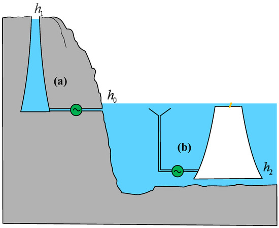
Figure 5.
The height exergy model of temperature exergy.
In Figure 5, (a) represents the height exergy model of temperature exergy from a heat source, while (b) corresponds to the height exergy model of temperature exergy from a cold source. From the equivalent model, it can be observed that the reservoir shape in the height exergy model approximates a conical structure, with a smaller cross-sectional area at the top and a larger cross-sectional area at the bottom. This pattern holds regardless of whether the reservoir is above or below the reference plane, and the cross-sectional area varies continuously with height.
4.3. The Temperature Exergy of Heat Sources and Cold Sources
The temperature exergy characteristics of heat sources and cold sources differ. As illustrated in Figure 5, under the same temperature difference relative to the ambient temperature, the equivalent liquid volume for a cold source is larger than that for a heat source, resulting in a greater work potential. Consequently, cold sources exhibit higher exergy values and greater energy storage density compared to heat sources. Taking 1 kg of air as an example, when the ambient temperature is 25 °C and the temperature differences are 25 °C, 50 °C, and 75 °C, the specific cold exergy values calculated using Equation (8) are 0.8 kJ, 3.39 kJ, and 8.16 kJ, respectively, as shown in Table 3. These values are 12%, 25%, and 41% higher than the corresponding specific heat exergy values, respectively.
Table 3.
Relationship between temperature difference and energy storage density.
Through the height exergy model of temperature exergy, the advantages of cold-source energy storage technology can be more intuitively observed. Similar to the transition from terrestrial pumped hydro storage to ocean-based pumped hydro storage, compressed CAES technology is also evolving toward cold-source energy storage. For instance, cryogenic liquefied air energy storage technology has emerged as a research hotspot. Liquid air exhibits a volumetric energy density of 150–180 kWh/m3 at cryogenic temperatures (−196 °C), significantly surpassing molten salts (80–120 kWh/m3 at 565 °C). Gravimetrically, liquid air maintains an advantage with 0.25–0.35 kWh/kg versus molten salts’ 0.15–0.25 kWh/kg, further validating the premise that cryogenic phase-change storage outperforms high-temperature sensible heat storage for air-based systems.
5. Applications in Hybrid PHS–CAES System
By integrating the strengths of the CAES and PHS systems, the hybrid PHS–CAES system can markedly enhance the overall performance of energy storage systems, particularly in terms of efficiency, geographical adaptability, renewable energy integration, and economic viability [30,31]. In this section, a typical PHS–CAES hybrid system is analyzed, and the energy storage capacity is calculated using mathematical models of height exergy and temperature exergy. Additionally, a height-based exergy model for the partial energy storage capacity of the hybrid system is presented.
5.1. A Typical Hybrid PHS–CAES System
Figure 6 illustrates the schematic diagram of a typical hybrid PHS–CAES system. The hybrid PHS–CAES system features an air–water mixing pressure vessel (PV) positioned at a specific height. The PV is connected to the underground air storage tank (AST) via piping and valves. Both the PV and AST are pre-pressurized with a certain amount of air. During system operation, all connected valves are in the open position. The valves are closed to ensure that there is no gas leakage in the AST between the energy storage process and the power generation process. During energy storage, a motor (M) drives pump to draw water from a lower reservoir into the PV, compressing the air within the PV and AST until all the air in the PV is transferred to the AST, leaving the PV fully filled with water. The power generation process operates in reverse.
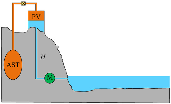
Figure 6.
Schematic diagram of a typical hybrid PHS–CAES system.
5.2. Analysis of Energy Storage Capacity of PHS–CAES Hybrid System
The energy storage capacity of the system can be calculated by the theoretical work done by the pump in the process of energy storage [32]. If the volumes of the PV and AST are Vp and Vs, respectively, the theoretical work of the pump can be calculated by:
where p(V) represents pump outlet pressure, comprising hydrostatic pressure and compressed air pressure. Ignoring the height impact of PV, p(V) can be expressed by:
where p(V) represents pump outlet pressure, comprising liquid pressure and air pressure. Considering air compression influenced by air–water interaction (polytropic exponent n), with initial pressure p1 of air, the relationship between air pressure and volume becomes:
The theoretical work output during storage is:
For adiabatic (n = 1.4) or isothermal (n = 1) processes, the theoretical work output equals the energy storage of the system, indicating no thermodynamic losses. However, polytropic processes induce entropy generation due to irreversible heat transfer between air and liquid. As a consequence, the energy storage of the system is lower than the theoretical work. To simplify calculations of energy storage capacity, the total exergy of the hybrid PHS–CAES system Ex can be divided into three components, as shown in Figure 7. Firstly, Ex1 stands for the height exergy, which can be treated as the constant-height model because the impact of height can be ignored. Secondly, Ex2 is the temperature exergy of air stored in AST, the temperature of which is related to polytropic processes. Thirdly, Ex3 shows the expansion potential energy generated by the change in air volume, which only considers the work capacity generated by the volume change at ambient temperature.
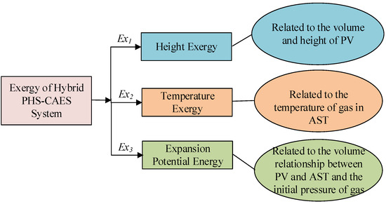
Figure 7.
Composition of exergy in PHS–CAES hybrid system.
As for the height exergy of water in PV, Ex1 can be calculated using the constant-height model:
Temperature exergy of air in AST, Ex2, can be calculated by:
where air temperature Ts during storage follows a polytropic relation:
Expansion potential energy, Ex3, needs to consider the impact of ambient pressure, which can be calculated by:
The total system exergy is:
By deduction, it can be concluded that when n = 1.4 (compressed in an adiabatic change process), Ex = Wsys. This also proves the correctness of the decomposition process and the applicability of height exergy and temperature exergy. By calculating Ex1 based on the liquid height, Ex2 based on the temperature of the stored air, and E3 based on the volume of the AST and PV, the energy storage capacity of the system can be accurately obtained. When the temperature of the air stored in the VST fluctuates, the temperature exergy model can be used to accurately calculate the change in the system’s energy storage capacity. It should be noted that regardless of the thermodynamic process experienced during compression, the value of Ex3 in this system remains constant, as it is only related to the volume of the container.
If Ex1 and Ex2 are both expressed using the height model, the partial energy storage of the system can be represented in the form of a stepped pumped storage power station, as shown in Figure 8. However, it should be noted that Ex1 stores water volume and Ex2 stores heat, so the two liquids cannot be connected.
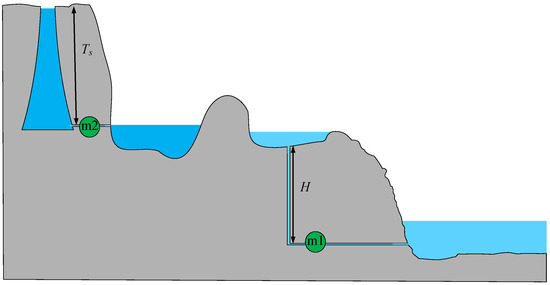
Figure 8.
Height exergy model of Ex1 and Ex2.
5.3. Case Study
Based on the above mathematical model, a specific hybrid PHS–CAES system is analyzed. The parameter settings for the hybrid system are shown in Table 4.
Table 4.
Parameter settings of hybrid PHS–CAES system.
Under different heat transfer coefficients in the PV, the air compression process exhibits a polytropic process. The final temperature and temperature exergy corresponding to the polytropic exponent are shown in Figure 9.
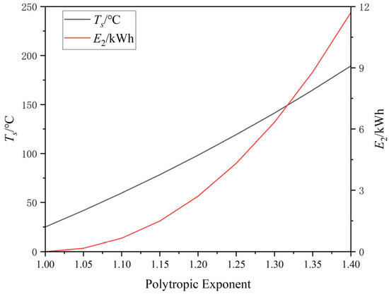
Figure 9.
The final temperature and temperature exergy corresponding to different polytropic exponents.
It is evident that in an isothermal compression process with n = 1, the air temperature remains unchanged, implying a temperature exergy of 0. When n = 1.4, the air undergoes adiabatic changes, reaching a maximum temperature of 189 °C, with a corresponding temperature exergy of 11.7 kWh. Both E1 and E3 in this system maintain constant values of 83.3 kWh and 43.0 kWh, respectively. If the temperature in the AST is not maintained and drops to the ambient temperature, the adiabatic process would incur a system loss of 8.5%.
Due to irreversible heat exchange processes occurring during the polytropic process, the theoretical available work exceeds the energy storage capacity. The relationship between the proportion of losses and the polytropic exponent is shown in Figure 9.
As Figure 10 describes, when the air exhibits isothermal or adiabatic process changes, irreversible heat exchange does not occur, and the loss is zero. It should be noted that the adiabatic process here is an ideal reversible process, without considering the influence of entropy production, and is more accurately expressed as an isentropic process. As the polytropic exponent increases, irreversible losses show a trend of first increasing and then decreasing. When the polytropic exponent n = 1.2, the theoretical loss accounts for the largest proportion, which is 2.06%.
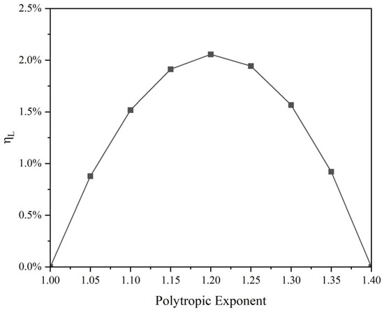
Figure 10.
Relationship between the proportion of losses and polytropic exponent.
6. Conclusions
This paper establishes the foundational concepts of height exergy within pumped hydroelectric storage (PHS) systems and temperature exergy for compressed air energy storage (CAES), formally defining height exergy as the available work generated by gravitational potential differences and temperature exergy as the available work arising from thermal gradients. Specifically, height exergy includes both the above-reference-level terrestrial pumped hydro storage and below-reference-level ocean pumped hydro storage, while temperature exergy includes both heat-source energy storage (higher than the ambient temperature) and cold-source energy storage (lower than the ambient temperature), collectively enabling the comprehensive quantification of thermomechanical work potential across energy storage topologies.
Furthermore, this paper establishes the mathematical models for height exergy and temperature exergy, providing detailed derivations of the mathematical expressions for both, as well as for constant-height models and constant-temperature models. The temperature exergy is derived from internal exergy and proven through the Maxwell relation and the decoupling method of internal exergy. Based on the similarity of the analysis methods for height exergy and temperature exergy, a comparative analysis of their relationship is conducted. It is concluded that the heat in temperature exergy can be analogized to the water volume in height exergy, with the heat dissipation from heat sources and the heat absorption from cold sources analogous to the water storage and water discharge in terrestrial and ocean pumped hydro storage, respectively.
In addition, to facilitate an intuitive understanding of temperature exergy, this paper establishes the height exergy model for temperature exergy under constant-volume heat capacity, equating the work process of a micro-Carnot heat engine with the pumped storage process. The equivalent model suggests that the shape of the storage pool is approximately a cone with a narrow top and a wide bottom, and the cross-sectional area is inversely proportional to the height. The model also clearly indicates that, under the same temperature difference, cold sources have a higher energy storage density.
A hybrid PHS–CAES system is proposed to verify the mathematical models of height exergy and temperature exergy. It uses a water pump to compress air until the air is fully stored. The system involves various forms of exergy, such as height exergy and temperature exergy. Considering the influence of polytropic exponent on the energy storage of the system during the compression process, the calculation is simplified, and the correctness of the calculation results is verified by decomposing the three forms of exergy in comparison with the theoretical work of the water pump calculation. During the adiabatic process, the energy stored in the system is the same as the theoretical work of the water pump, and the heat transfer loss of the system follows an approximate parabolic form with respect to the polytropic exponent. The loss reaches its maximum when the polytropic exponent is 1.2. This case only consists of single-stage PHS and single-stage CAES. In the future, this theoretical method can be applied in complex systems with multi-stage PHS and multi-stage CAES to further enhance its value in engineering applications.
Author Contributions
Conceptualization, T.J. and Y.C.; methodology, Y.C.; software, Y.C.; validation, T.J.; formal analysis, Y.C.; investigation, M.L.; resources, M.L.; data curation, M.L.; writing—original draft preparation, Y.C.; writing—review and editing, M.L.; visualization, Y.C.; supervision, T.J. All authors have read and agreed to the published version of the manuscript.
Funding
This research received no external funding.
Data Availability Statement
Data are contained within the article.
Acknowledgments
The authors acknowledge the support of the State Key Laboratory of Alternate Electrical Power System with Renewable Energy Sources and the technical support of the Shanghai Investigation, Design, and Research Institute.
Conflicts of Interest
The authors declare no conflicts of interest.
Abbreviations
| PHS | Pumped Hydroelectric Storage |
| CAES | Compressed Air Energy Storage |
| AA-CAES | Advanced Adiabatic Compressed Air Energy Storage System |
| PHS–CAES | Pumped Hydroelectric Storage and Compressed Air Energy Storage |
| PV | Pressure Vessel |
| AST | Air Storage Tank |
| M | Motor |
| Symbols | |
| W | Work (J) |
| h | Height (m) |
| Rg | Air Constant (J/kg K−1) |
| T | Temperature (°C or K) |
| p | Pressure (MPa) |
| v | Specific Volume (m3/kg) |
| V | Volume (m3) |
| s | Specific Entropy (J/kg·K−1) |
| S | Surface (mm2) |
| Ex | Exergy (J) |
| N | Molecular Density (dimensionless) |
| CV | Constant Volume Heat Capacity (J/K−1) |
| u | Specific Internal Energy (J) |
| ρ | Density (kg/m3) |
References
- Frede, B.; Yang, Y.; Kim, K.A.; Rodriguez, J. Power electronics technology for large-scale renewable energy generation. Proc. IEEE 2023, 111, 335–355. [Google Scholar]
- Gu, Y.; Green, T.C. Power System Stability with a High Penetration of Inverter-Based Resources. Proc. IEEE 2023, 111, 832–853. [Google Scholar] [CrossRef]
- Roy, P.; He, J.; Zhao, T.; Singh, Y.V. Recent Advances of Wind-Solar Hybrid Renewable Energy Systems for Power Generation: A Review. IEEE Open J. Ind. Electron. Soc. 2022, 3, 81–104. [Google Scholar] [CrossRef]
- Ghofrani, M.; Arabali, A.; Etezadi-Amoli, M.; Fadali, M.S. A Framework for Optimal Placement of Energy Storage Units Within a Power System with High Wind Penetration. IEEE Trans. Sustain. Energy 2013, 4, 434–442. [Google Scholar] [CrossRef]
- Brian, A. Renewable Energy Integration and Energy Storage: Challenges and Solutions, 1st ed.; Springer: Singapore, 2014; pp. 1–16. [Google Scholar]
- Li, X.; Hui, D.; Lai, X. Battery Energy Storage Station (BESS)-Based Smoothing Control of Photovoltaic (PV) and Wind Power Generation Fluctuations. IEEE Trans. Sustain. Energy 2013, 4, 464–474. [Google Scholar] [CrossRef]
- Calero, F.; Cañizares, C.A.; Bhattacharya, K.; Anierobi, C.; Calero, I.; de Souza, M.F.Z.; Violante, W. A Review of Modeling and Applications of Energy Storage Systems in Power Grids. Proc. IEEE 2023, 111, 806–831. [Google Scholar] [CrossRef]
- Peng, F.Z.; Liu, C.C.; Li, Y.; Jain, A.K.; Vinnikov, D. Envisioning the Future Renewable and Resilient Energy Grids—A Power Grid Revolution Enabled by Renewables, Energy Storage, and Energy Electronics. IEEE J. Emerg. Sel. Top. Ind. Electron. 2024, 5, 8–26. [Google Scholar] [CrossRef]
- Fang, B.; Ren, X.; Lin, W.; Li, H.; He, G.; Zhou, W. Analysis of the Influence of Large-Scale Integration of Centralized Energy Storage into the Power Grid on Voltage Security and Stability of Power System. In Proceedings of the 2021 3rd Asia Energy and Electrical Engineering Symposium (AEEES), Chengdu, China, 26–29 March 2021. [Google Scholar]
- Zhao, Z.; Hu, H.; He, Z.; Zhu, H.; Davari, P.; Blaabjerg, F. Advanced Solid-State Lithium Battery and Its Safety. CPSS Trans. Power Electron. Appl. 2023, 8, 348–362. [Google Scholar] [CrossRef]
- Sanin-Villa, D.P.D. Parametric and Economic Analysis of a Pumped Storage System Powered by Renewable Energy Sources. J. Adv. Res. Fluid Mech. Therm. Sci. 2021, 84, 43–59. [Google Scholar]
- Magableh, M.A.K.; Radwan, A.; Mohamed, Y.A.R.I.; El-Saadany, E.F. A Novel Reduced-Order Modeling Approach of a Grid-Tied Hybrid Photovoltaic–Wind Turbine–Battery Energy Storage System for Dynamic Stability Analysis. IEEE Open J. Power Electron. 2024, 5, 1459–1483. [Google Scholar] [CrossRef]
- Chen, G. Engineering Thermodynamics, 11th ed.; Tsinghua University Press: Beijing, China, 2020; pp. 280–311. [Google Scholar]
- Mostashar Shahidi, S.M.; Esmaeili Shayan, M.; Najafi, G.; Mazlan, M. Exergy and energy analysis of Organic Rankine Cycle integration in the carbon black industry using pinch technology. Therm. Sci. Eng. Prog. 2023, 46, 102160. [Google Scholar] [CrossRef]
- Esmaeili Shayan, M.; Ghasemzadeh, F.; Rouhani, S.H. Energy storage concentrates on solar air heaters with artificial S-shaped irregularity on the absorber plate. J. Energy Storage 2023, 74, 109289. [Google Scholar] [CrossRef]
- Dupin, V.; Teixeira, D. Advanced adiabatic compressed air energy storage systems dynamic modelling: Impact of the heat storage device. Heliyon 2025, 11, e40730. [Google Scholar] [CrossRef]
- Zhang, Y.; Wang, H.; Jin, P.; Cai, X.; Du, J.; Zhang, W.; Wang, H.; Li, R.; Cheng, Z. Design and thermodynamic performance analysis of a novel adiabatic compressed air energy storage system based on liquid piston re-pressurization. J. Energy Storage 2025, 105, 114675. [Google Scholar] [CrossRef]
- Gong, L.; Li, Y.; Wang, Y.; Zhang, Y. Study on the peak shaving performance of coupled system of compressed air energy storage and coal-fired power plant. J. Energy Storage 2025, 107, 114954. [Google Scholar] [CrossRef]
- Julian, D.H.; Marcos, A.V.F.; Amaro, O.P.J. Enhanced-Pumped-Storage: Combining pumped-storage in a yearly storage cycle with dams in cascade in Brazil. Energy 2014, 78, 513–523. [Google Scholar]
- Pottie, D.L.; Ferreira, R.A.; Maia, T.A.; Porto, M.P. An alternative sequence of operation for Pumped-Hydro Compressed Air Energy Storage (PH-CAES) systems. Energy 2020, 191, 116472. [Google Scholar] [CrossRef]
- Stergios, E.; Efthymios, I.N.; Baptiste, F.; Casey, B.; Emmanouil, N.A. Evaluating existing water supply reservoirs as small-scale pumped hydroelectric storage options—A case study in Connecticut. Energy 2021, 226, 120354. [Google Scholar]
- Mélanie, G.; Massimiliano, C.; Ludovic, G.; Franco, R.; François, V.; François, A. Study of the drivers and asset management of pumped-storage power plants historical and geographical perspective. Energy 2016, 111, 560–579. [Google Scholar]
- Dimitris Al, K.; Dimitris, G.C.; Ioannis, S.; Petros, S.; Nikos, S. Technical details regarding the design, the construction and the operation of seawater pumped storage systems. Energy 2013, 55, 619–630. [Google Scholar]
- Padrón, S.; Medina, J.F.; Rodríguez, A. Analysis of a pumped storage system to increase the penetration level of renewable energy in isolated power systems. Gran Canaria: A case study. Energy 2011, 36, 6753–6762. [Google Scholar] [CrossRef]
- Dimitris Al, K.; Dimitris, G.C. Seawater pumped storage systems and offshore wind parks in islands with low onshore wind potential. A fundamental case study. Energy 2014, 66, 470–486. [Google Scholar]
- Lu, M. Engineering Thermodynamics, 7th ed.; Tsinghua University Press: Beijing, China, 2019; pp. 139–151. [Google Scholar]
- Kim, Y.M.; Favrat, D. Energy and exergy analysis of a micro-compressed air energy storage and air cycle heating and cooling system. Energy 2010, 35, 213–220. [Google Scholar] [CrossRef]
- Ukalovich, N. Engineering Thermodynamics (Volume I); Qiu, L., Xia, W., Eds.; Water Resources and Hydropower Press: Beijing, China, 1999. [Google Scholar]
- Cao, R.; Li, W.; Wang, S.; Yang, H.; Kuang, C. Comprehensive comparative study of two novel isobaric adiabatic compressed air energy storage systems coupled with pumped hydro storage. Appl. Therm. Eng. 2024, 257, 124318. [Google Scholar] [CrossRef]
- Bennett, J.A.; Fitts, J.P.; Clarens, A.F. Compressed air energy storage capacity of offshore saline aquifers using isothermal cycling. Appl. Energ. 2022, 325, 119830. [Google Scholar] [CrossRef]
- Cheekatamarla, P.K.; Kassaee, S.; Abu-Heiba, A.; Momen, A.M. Near isothermal compressed air energy storage system in residential and commercial buildings: Techno-economic analysis. Energy 2022, 251, 123963. [Google Scholar] [CrossRef]
- Li, R.; Tao, R.; Yao, E.; Chen, H.; Zhang, H.; Xu, X.; Wang, H. Comprehensive thermo-exploration of a near-isothermal compressed air energy storage system with a pre-compressing process and heat pump discharging. Energy 2023, 268, 126609. [Google Scholar] [CrossRef]
Disclaimer/Publisher’s Note: The statements, opinions and data contained in all publications are solely those of the individual author(s) and contributor(s) and not of MDPI and/or the editor(s). MDPI and/or the editor(s) disclaim responsibility for any injury to people or property resulting from any ideas, methods, instructions or products referred to in the content. |
© 2025 by the authors. Licensee MDPI, Basel, Switzerland. This article is an open access article distributed under the terms and conditions of the Creative Commons Attribution (CC BY) license (https://creativecommons.org/licenses/by/4.0/).