Abstract
In air-conditioning compressors operating under ultra-low temperature conditions, both the rotational speed and load torque are at high levels, demanding pump motors that offer high efficiency and high power at high speeds. Electrically excited synchronous motors (EESMs) satisfy these operational requirements by leveraging their inherent wide-speed field-weakening capability and superior high-speed performance characteristics. Current research on EESM primarily targets electric vehicle applications, with a high-efficiency design focused on medium and low speeds. Excitation design under constant-power–speed extension remains insufficiently explored. To address it, this paper proposes an EESM design methodology optimized for high-speed efficiency and constant-power excitation control. Key EESM parameters are determined through a dynamic phasor diagram, and design methods for turn number, split ratio, and other parameters are proposed to extend the high-efficiency region into the high-speed range. Additionally, a power output modulation strategy in the field-weakening region is introduced, enabling dynamic high-power regulation at high speed through excitation adjustment. Compared to similarly sized PMSMs, the proposed EESM exhibits consistently superior efficiency beyond 10,000 rpm, delivering 19% and 49% higher power output at 12,000 rpm and 14,000 rpm, respectively, relative to conventional pump-drive PMSMs. Experimental validation via a prototype confirms excellent high-speed efficiency and sustained constant-power performance, in alignment with the design targets.
1. Introduction
Air-conditioning compressors in cold and tropical regions typically operate for extended periods in ultra-low-temperature heating or refrigeration modes, with the pump motor subjected to high rotational speeds and elevated average gas load torque. These prolonged heavy-duty conditions demand high-speed pump motors featuring extended speed capability, high efficiency, and constant-power output performance at elevated speeds.
Conventional pump motors predominantly employ PMSM, which rely on demagnetizing current for field weakening at high speeds. This leads to reduced efficiency in high-speed regions, a limited constant-power operating range, and increased risk of irreversible magnet demagnetization due to elevated temperatures [1].
The EESM enables extended speed range and power output through adjustable excitation, enhancing high-speed efficiency [2], and is particularly well-suited for compressor pump applications requiring high-efficiency performance at elevated speeds. In recent years, EESM optimization has primarily targeted electric vehicle applications. Refs. [3,4,5] present comparative analyses between EESM and the Prius IPMSM, showing that the high-efficiency region of EESM is similar to PMSM, with peak efficiency up to 1.3% lower. However, in high-speed regions, EESM demonstrates superior torque output and improved efficiency. Ref. [6] compares PMSM and EESM for long-range electric vehicles, showing that after optimization, both exhibit high-efficiency regions near the base speed, with EESM offering superior efficiency at higher speeds. To further enhance EESM’s efficiency map, Refs. [7,8] propose a multi-objective optimization (MOP) metamodel-based approach. The optimized brushless EESM achieves a peak efficiency of 95% at 4000 r/min [9]. Additionally, Refs. [10,11,12] improve EESM efficiency through excitation winding configurations, asymmetric rotor structures, and slot geometry designs; however, these works do not address modulation of the efficiency region distribution.
Table 1 summarizes the speed distribution of high-efficiency regions in existing studies, where k denotes the ratio of the high-efficiency point speed to the base speed. While prior research consistently indicates that EESM outperforms PMSM in high-speed efficiency, most EESM optimization efforts remain focused on medium and low-speed regions. As a result, the high-efficiency zone typically aligns with the constant-torque region, mirroring the characteristics of automotive PMSM. This design trend is not well-suited to the high-speed, concentrated load conditions of pump motors. Moreover, limited work has been conducted to exploit EESM’s advantages by extending the high-efficiency region into the high-speed field-weakening domain.

Table 1.
Speed distribution in the motor high-efficiency region.
Beyond structural design, EESMs can regulate operational characteristics via excitation magnetomotive force to extend the high-speed constant-power region. Refs. [13,14] analyze the external power characteristic curve, showing that with id = 0, output power decreases as speed increases. They establish a macroscopic criterion for achieving constant-power operation at high speeds: effective field weakening requires that the stator current alone can fully counteract the maximum excitation field. Additionally, researchers have proposed excitation design criteria for achieving unity power factor under specific operating conditions [15] and developed control strategies targeting minimum total copper loss and minimum excitation copper loss [16]. A dynamic excitation current reference based on copper loss–torque characteristics has also been introduced to enhance efficiency across a wider operating range [17]. However, existing dynamic excitation control primarily focuses on efficiency optimization, with limited attention to the design of boundary power output characteristics in the high-speed region.
Existing studies have established the macroscopic principle that excitation adjustment enables regulation of EESM power output. However, for pump motors requiring a wide speed range and high power, detailed excitation design during speed expansion and the resulting variations in the external power characteristic curve remain insufficiently explored. Furthermore, current excitation control strategies primarily aim at efficiency improvement, falling short of addressing the specific high-speed performance demands of pump applications.
To address the limitations of existing research, this paper proposes a design and dynamic excitation control method for an EESM that achieves both high efficiency and high power output at high speeds. Key structural parameters are determined through dynamic phasor analysis, and a parameter design approach, covering turn number and split ratio, is presented based on high-efficiency region modulation. By dynamically adjusting excitation, the power characteristic curve is shaped in the field-weakening speed range to extend the constant-power region. The proposed method is benchmarked against a PMSM through simulation, and high-speed experimental validation is conducted using a developed prototype.
2. Design of High-Efficiency Output Characteristics of EESM
To meet the high-efficiency and constant-power output requirements of pump motors at elevated speeds, the EESM design should focus on: (1) shaping the torque and power output characteristics to shift the high-efficiency region toward the high-speed range; (2) optimizing excitation design to extend the constant-power region and mitigate power degradation at high speeds. Figure 1 illustrates the structural configuration of the proposed EESM.
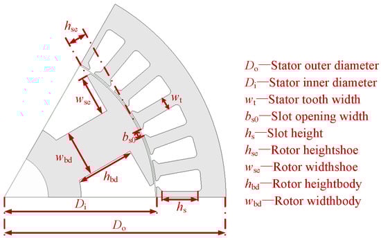
Figure 1.
Structural schematic of the EESM.
The efficiency region distribution of an EESM is closely linked to its torque and power characteristic curves. Based on the relationships among motor main dimensions, power, speed, and electromagnetic loading, as shown in Equations (1) and (2), the transition speed of the characteristic curve is influenced by the parameters in Equation (3). As factors such as the pole arc coefficient , air-gap flux waveform coefficient , air-gap flux density , and core length exhibit minimal variation, the transition speed is primarily determined by the armature winding factor , number of series turns per phase , and armature diameter (approximately the rotor outer diameter).
The armature winding coefficient is defined by the pole-slot combination and winding configuration. The number of turns per phase depends on the number of winding layers and turns per layer, while the rotor outer diameter is governed by the stator split ratio. To achieve the desired high-speed performance and high-efficiency modulation, this section addresses design optimization from three aspects: pole-slot combination, stator turn adjustment, and stator split ratio with associated structural parameters.
2.1. High-Efficiency Design at High Speed
As a design example, a pump motor for air-conditioning compressors in cold-region applications is considered. The key specifications are summarized in Table 2, including the maximum torque in the constant-torque region, output power in the high-speed region, and peak efficiency requirement at high speed.
Table 2.
Design requirements for the pump motor.
2.1.1. Pole-Slot Combination
This study adopts a 3-pole-pair configuration and investigates three representative winding schemes: 6-pole 9-slot fractional-slot concentrated winding, and 6-pole 36-slot and 54-slot integer-slot distributed windings with varying slots per pole per phase. The 6p9s topology offers simplified harmonic characteristics, while the 6p36s and 6p54s employ double-layer short-pitch distributed windings. Key parameters, including winding factors and dominant tooth harmonics, are summarized in Table 3.
Table 3.
Winding factor.
The 6p9s configuration yields the lowest fundamental winding factor, which, according to Equation (3), results in the highest transition speed but limits torque output at a given power level. It also introduces prominent low-order tooth harmonics and experiences significant fundamental component attenuation due to skewing. Therefore, the 6p36s and 6p54s configurations are preferred for improved performance.
With identical maximum power output and fixed series turns per phase (N), the three-pole-slot EESM configurations exhibit similar torque characteristics. Figure 2 presents a comparison of their high-efficiency region distributions.
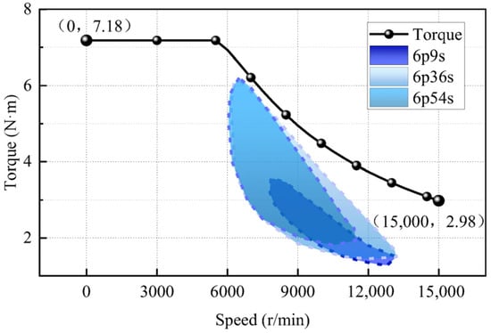
Figure 2.
Comparison of high-efficiency regions for 6p9s, 6p36s, and 6p54s configurations.
With an identical turn number, the 6p36s configuration yields the most favorable high-efficiency distribution. Compared to 6p54s, a higher slot count increases the risk of tooth saturation, leading to greater iron losses and reduced efficiency. From a manufacturing perspective, excessive slot numbers reduce per-slot area, and insulation requirements further constrain the achievable slot fill factor. Based on Equation (3), when the impact on high-efficiency region distribution is comparable, priority is given to pole-slot combinations with higher fundamental winding factors and broader high-efficiency coverage. In this design, the 6p36s is selected.
2.1.2. Stator Turn Adjustment
The series turns per phase significantly affect the transition speed, thereby influencing the distribution of the motor’s external characteristic curve. To evaluate this impact, the DC bus voltage is held constant, with the turns per layer selected as the design variable. Stator and rotor excitation levels are synchronously adjusted to maintain constant maximum output power. Figure 3 illustrates the resulting torque-speed (T-n) characteristics and high-efficiency region distribution. Performance under high-speed, high-power conditions (10,000 r/min, 4.3 N·m, 4.5 kW, as specified in Table 2) is compared in Table 4.
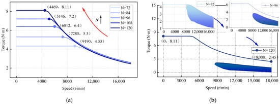
Figure 3.
Motor characteristic curves and high-efficiency region distribution map. (a) T-n characteristic curve; (b) High-efficiency region distribution.
Table 4.
Stator turn variation.
Based on the results in Figure 3 and Table 4, increasing the stator series turns per phase reduces the transition speed, enhances torque in the constant-torque region, and shifts the T–n characteristic from a flat to a vertically extended profile. At 10,000 r/min, the field-weakening depth increases, and the stator current lead angle grows. As the id component of stator current increases and iq decreases, maintaining torque and power output necessitates a higher maximum excitation current if, leading to increased losses. The corresponding efficiency maps show that as turn count increases, the high-efficiency region shifts from high-torque/mid-speed toward medium-torque/high-speed operation, with a reduction in its overall area. Considering torque capability, high-speed performance, and efficiency region distribution, the turn count should align the torque boundary with the maximum torque requirement without excessively reducing the transition speed. Based on this trade-off, eight turns per phase is selected.
2.1.3. Stator Split Ratio and Structural Parameter Optimization
Following efficiency region modulation, key EESM parameters are further optimized to enhance high-speed efficiency. During excitation adjustment, Figure 4 illustrates the motor’s dynamic phasor diagram under increasing speed. Five key variables govern output performance: id, iq, Xd (Ld), Xq (Lq), E0f (if). Unlike PMSMs, EESM design must additionally consider the coordinated excitation between stator and rotor windings (id, iq, if) and the d-q axis magnetic circuit design of the wound-rotor topology (Ld, Lq). The corresponding relationships to structural parameters are as follows:
Armature and field Winding—id, iq, if → Stator Split Ratio
Rotor d–q Axis Magnetic Circuit—Ld, Lq → Rotor Pole Body and Shoe
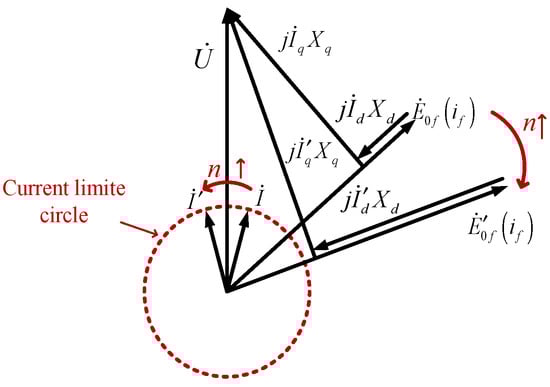
Figure 4.
EESM dynamic phasor diagram.
Furthermore, according to Equation (3), with a fixed motor outer diameter, the stator split ratio determines the rotor outer diameter, directly influences torque output, armature-to-excitation loss balance, and overall efficiency. Based on the rotor’s main structural parameters, EESM optimization is performed to meet the high-speed maximum power requirement specified in Table 2. The optimization variables and objectives are outlined below.
Operating condition: High-speed point at 10,000 r/min, 4.3 N·m torque
Optimization variables: Stator split ratio, rotor pole shoe width/height, rotor pole body width/height, stator tooth width, etc.
Constraints: DC bus voltage ≤ 385 V; RMS phase current ≤ 11 A; torque output > 4.3 N·m
Objectives: Maximize output torque and efficiency
This paper employs a multi-objective global optimization method based on natural selection and genetic principles—Evolutionary Algorithm (EA). The initial sample size is set to 20, with 20 samples per generation and a maximum of 24 iterations, resulting in 500 sample points. The sample set and Pareto front are shown in Figure 5. After balancing torque and efficiency, the motor parameters corresponding to the red star point were selected as the optimal solution, with the parameters listed in Table 5.

Figure 5.
Optimization results—Pareto front curve.
Table 5.
Optimized parameters of EESM.
2.2. Constant-Power–Speed Regulation Design
The EESM’s adjustable excitation enables active flux regulation during speed extension, altering operational characteristics and extending the constant-power range at high speeds. To address the high-speed, high-power demands of pump motors, this section investigates the excitation-based speed regulation characteristics. At the power output boundary, where stator voltage and current reach their limits (Umax, Imax), Figure 6 shows power factor versus speed under three excitation conditions.
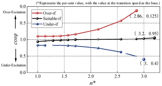
Figure 6.
Power factor variation with speed.
With initial under- or over-excitation, the cross-link flux remains approximately constant when if is held constant. Frequency and back-EMF increase linearly with speed, maintaining the respective excitation state. As the angle between U and I increases, the dynamic phasor diagrams are shown in Figure 7a,b. In contrast, moderate initial under-excitation results in a decreasing excitation current with rising speed, achieving unity power factor at a specific point before transitioning to over-excitation, as shown in Figure 4. At varying speeds, excitation adjustment dynamically regulates the current lead/lag angle relative to voltage, enabling active power control. For the EESM’s power output boundary characteristics, three dynamic excitation control strategies are proposed: unity power factor, lag–lead, and lag–unity power factor design. Corresponding excitation current and power factor variations with speed are illustrated in Figure 8.
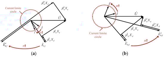
Figure 7.
Phasor diagrams of EESM under different excitation conditions. (a) under-excitation; (b) over-excitation.
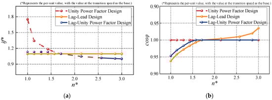
Figure 8.
Comparison of if and power factor variation. (a) if; (b) Power factor.
The unity power factor design enables constant power output across the entire speed range. At low speeds, a higher if ensures sufficient excitation E0f; as speed and frequency increase, if is reduced to avoid over-excitation. Ideally, maximum power is achieved at the transition speed when if peaks, after which power remains constant while if gradually decreases with speed, as shown by the red curve in Figure 8a.
The lag–lead design maintains a constant if, simplifying implementation and control. With appropriate if selection, the motor transitions from under-excitation to unity power factor and subsequently to over-excitation as speed increases. This results in rising power output up to a peak, followed by a decline, enabling sustained high-power operation over a defined speed range.
In the lag-to-unity power factor scheme, the motor initially operates under-excited during early field weakening. As speed increases, it transitions to unity power factor, with if subsequently reduced to maintain unity power factor operation. As shown in Figure 8a, achieving both unity power factor and maximum power at the onset of field weakening requires high excitation current, which may reduce efficiency and introduce rotor thermal risks. Introducing under-excitation over a defined speed range lowers excitation demand prior to reaching unity power factor, as illustrated by the blue curve.
In summary, as speed increases, Table 6 compares the three designs in terms of excitation current, power factor, output power, rotor heating, excitation power supply capacity, and control complexity. Figure 9 compares the torque and power characteristics of the three schemes. The unity power factor design provides optimal output performance but incurs the highest excitation demand and the most significant rotor heating. In contrast, the lag–lead design maintains constant maximum excitation, enabling simpler implementation, while the lag–unity power factor design requires dynamic excitation adjustment, increasing control complexity but extending the constant-power range. Considering excitation supply capacity, cost, and control requirements for the compressor pump motor, the latter two strategies are preferred.
Table 6.
Comparison of the three designs.
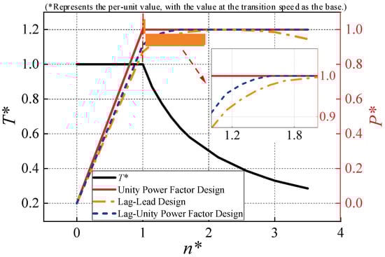
Figure 9.
Comparison of motor characteristics under three excitation strategies.
3. Finite Element Simulation: Comparison and Analysis
To further compare the operational characteristics of the proposed EESM and the conventional pump PMSM, the existing compressor pump PMSM from Table 2 is modeled. Figure 10 shows the 2D finite element models, and Table 7 summarizes their detailed specifications for comparison.
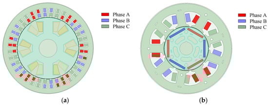
Figure 10.
EESM and existing pump PMSM models. (a) EESM; (b) PMSM.
Table 7.
Parameters of EESM and PMSM.
3.1. High-Speed Region Efficiency
Efficiency calculations include stator and rotor copper losses, core losses, and eddy-current losses in the permanent magnets.
Since the stator winding of the motor in this paper uses a round wire design, with a high number of turns per slot and parallel turns, the AC copper loss is relatively small. Therefore, the focus is on armature and excitation DC copper losses, as shown in Equation (4). The core loss calculation is given by Equation (5), with the three components corresponding to hysteresis, eddy, and other losses. Figure 11 presents the maps of stator copper loss, excitation copper loss, and core loss, along with the variations in the proportion of copper and core loss in total loss under different loading conditions. It is evident that copper loss is related to current and increases with torque, while core loss is primarily determined by frequency, increasing with speed.
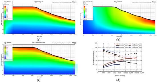
Figure 11.
Maps of copper loss and core loss. (a) Stator copper loss; (b) Core loss; (c) Field copper loss; (d) Loss proportion.
Furthermore, the electromagnetic torque expression for the EESM is given by Equation (6) [17]. Unlike permanent magnet machines, the d-axis flux linkage is dependent on the excitation current. Combining the above loss analysis, the efficiency calculation for the EESM is provided in Equation (7).
Figure 12 compares the efficiency maps of the EESM and PMSM over the 0–15,000 r/min range at 25 °C. The EESM demonstrates increasing efficiency with speed, with its high-efficiency region concentrated above 1.5 times the transition speed. Peak efficiency is achieved in the mid-torque range at 2 times transition speed, consistent with the design targets. In contrast, the PMSM’s high-efficiency region is primarily concentrated near the transition speed in the medium-to-high torque range.
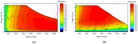
Figure 12.
Efficiency maps of EESM and PMSM. (a) EESM; (b) PMSM.
Quantitatively, the EESM achieves a peak efficiency of 96.7%, slightly lower than the PMSM’s 97.1%, attributed to the inherently higher theoretical efficiency limits of permanent magnet machines due to superior power density. In terms of high-efficiency area distribution, the percentage coverages for efficiency thresholds >96%, >95%, >94%, >93%, >92%, and >90% are: EESM 18.5% vs. PMSM 19.2%; 47.6% vs. 38.7%; 59.7% vs. 50.0%; 67.2% vs. 58.1%; 72.2% vs. 64.2%; and 78.3% vs. 72.3%, respectively. Notably, the EESM exhibits broader high-efficiency coverage, particularly in the high-speed region.
Figure 13 shows the efficiency difference map (EESM minus PMSM). At low speeds, the PMSM holds an efficiency advantage due to dominant copper losses, which are further compounded in the EESM by excitation copper losses. As speed increases, the efficiency gap gradually narrows. Beyond the transition speed, the EESM consistently surpasses the PMSM, with the efficiency advantage increasing under constant-power operation at higher speeds.
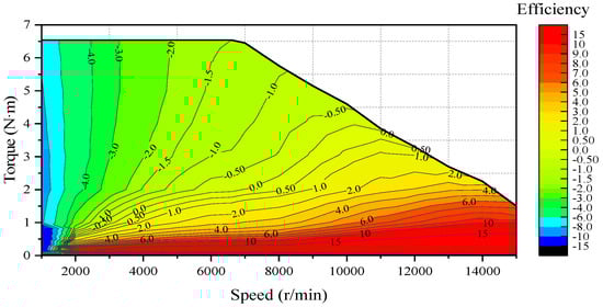
Figure 13.
Efficiency difference map between EESM and PMSM.
3.2. Power Output Characteristic
Under constrained conditions of DC bus voltage (385 V) and stator phase current (11 A rms), Figure 14 compares the torque–speed and power–speed characteristics of the EESM and PMSM. Both machines deliver similar maximum torque (6.54 N·m and 6.55 N·m) with transition speeds of 6500 r/min and 6600 r/min, respectively. Beyond these points, the PMSM exhibits rapid torque decline in the high-speed region.
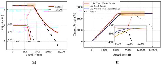
Figure 14.
Characteristic curves of EESM and PMSM. (a) T-n curve; (b) P-n curve.
Figure 14b compares the power–speed characteristics of three EESM control strategies—unity power factor, lag–lead, and lag–unity power factor, alongside a permanent magnet synchronous motor (PMSM). While all configurations achieve similar peak output power, their operational behaviors differ markedly. The unity power factor EESM reaches peak power at the transition speed and maintains a near-constant output thereafter. The lag–lead design, with fixed 4 A excitation current, exhibits rising power output up to 11,000 r/min, followed by a decline. The lag–unity power factor design sustains quasi-constant power beyond the peak via dynamic excitation control, consistent with the theoretical analysis. In contrast, the PMSM shows continuous power reduction beyond 10,000 r/min due to limited field-weakening capability. These results highlight the EESM’s superior constant-power performance in high-speed operation.
A comprehensive comparison under identical volume and voltage/current excitation conditions (Figure 15) shows that, while maintaining comparable constant-torque performance to the PMSM baseline, the EESM achieves a higher constant-power–speed ratio up to 15,000 r/min, higher high-speed efficiency, and broader high-efficiency coverage across the operating range.
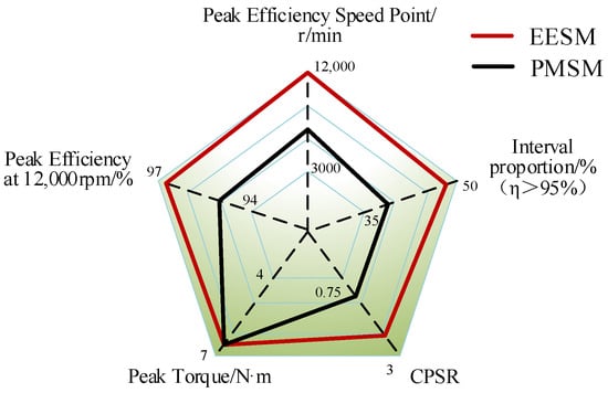
Figure 15.
Comparison of EESM and PMSM characteristics.
3.3. Cost Comparison
From a reliability perspective, both the stator and rotor of the EESM utilize copper-wire excitation, eliminating the risk of rare-earth magnet demagnetization. The rotor-side maintenance costs and lifespan of the EESM are superior to those of the PMSM.
From an economic perspective, the cost comparison between EESM and PMSM is shown in Table 8. The silicon steel weight of both motors is nearly identical. However, due to the additional rotor excitation winding in the EESM, its total weight is higher than that of the PMSM. The EESM also requires an excitation system to power the rotor winding, whereas the PMSM uses a certain amount of rare-earth permanent magnets. The unit prices of materials are determined by the respective suppliers, resulting in an overall cost reduction of approximately 31.7% for the EESM compared to the PMSM.
Table 8.
Cost parameters.
4. Experimental Validation
To validate the proposed EESM, a 6-pole 36-slot prototype was developed per the design specifications, as shown in Figure 16a. The stator incorporates a 10° skew, and the rotor employs a 6-pole salient-pole wound configuration. Measured winding resistances are listed in Table 9. The stator three-phase windings exhibit high symmetry, and the excitation winding resistance deviates by only 0.91% from the nominal value, well within acceptable tolerance.
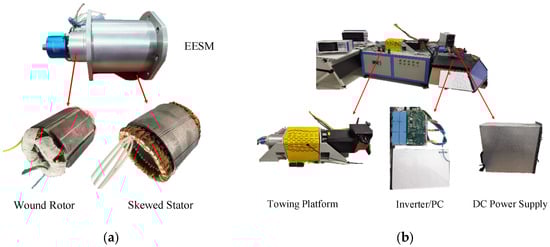
Figure 16.
Experimental prototype and test platform. (a) Proposed EESM; (b) Test platform.
Table 9.
Winding resistance parameters.
4.1. No-Load Experiment
At a speed of 1000 r/min, the no-load back-EMF characteristics of the EESM are measured with an excitation current of 4 A. Experimental back-EMF waveforms are compared with simulated waveforms for skewed and non-skewed configurations, as shown in Figure 17a, with FFT analysis results presented in Figure 17b.
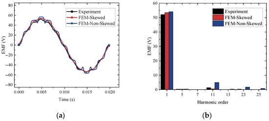
Figure 17.
EESM no-load experiment. (a) Line back-EMF; (b) FFT.
For the 6-pole 36-slot EESM, tooth harmonics are concentrated at the 11th, 13th, 23rd, and 25th orders, which are mitigated by rotor skew. Both simulation and experimental results show that the experimental harmonic content at the 11th and 23rd orders, along with waveform distortion, falls between the skewed and non-skewed simulation results, indicating that the suppression of tooth harmonics in the fabricated prototype is slightly insufficient. Overall, the measured back-EMF amplitude is close to the simulation, with a fundamental component error of 2.58%, within acceptable limits.
4.2. High-Speed Region Efficiency Measurement
To validate the motor’s efficiency performance, high-speed tests were conducted using maximum stator and rotor currents of 11 Arms and 4 Adc, respectively, with a DC bus voltage of 385 V, consistent with simulation parameters. Figure 18 shows the experimentally measured efficiency map of the EESM, exhibiting trends closely aligned with simulation results. The high-efficiency region is concentrated in the high-speed range, in accordance with the design targets. Peak measured efficiency exceeds 96% at 12,000 r/min, meeting the 95% requirement specified in Table 2. Efficiency values above 95% occur beyond the transition speed, and those above 96% emerge beyond 1.5 times the transition speed. Efficiency was measured at over 70 speed–torque operating points, with representative medium- and high-speed results listed in Table 10.
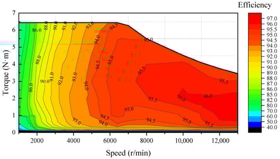
Figure 18.
EESM efficiency map measurement.
Table 10.
Efficiency measurement at selected medium-to-high-speed operating points.
As shown in Table 10, experimental and simulated efficiency trends in the medium-to-high speed range exhibit strong agreement. Measured efficiency exceeds 95% above 10,000 r/min, reaching over 96% at select operating points—slightly lower than simulated values. These results confirm the EESM’s ability to sustain high-efficiency performance in high-speed operation, validating the proposed design.
4.3. Output Power Characteristics Measurement
Figure 19 shows the measured T-n and P-n characteristics of the EESM. In the constant-torque region, the simulated and measured maximum torques are 6.54 N·m and 6.44 N·m, respectively, a deviation of 1.53%, both exceeding the 5.5 N·m requirement in Table 2. Transition speeds for both cases are approximately 6500 r/min.
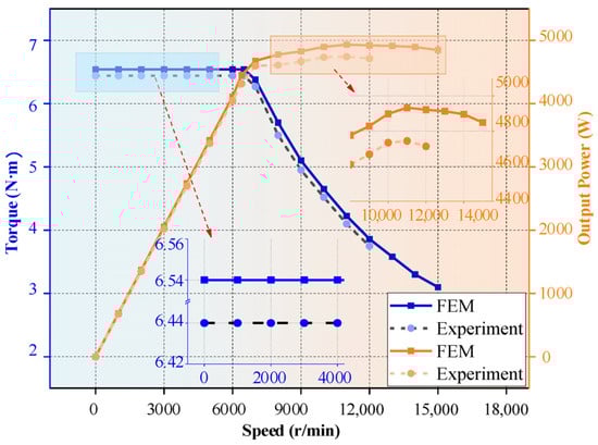
Figure 19.
EESM characteristic curve measurement.
In the high-speed field-weakening region, excitation is regulated using the lag–lead scheme with a fixed maximum excitation current of 4 A. The motor operates in an under-excited state at the transition speed, with output power gradually increasing and stabilizing at a constant of around 12,000 r/min. Both simulation and experimental results confirm robust constant-power performance, satisfying the 4.5 kW maximum power requirement. Accounting for differences between simulated and actual material properties, as well as manufacturing tolerances, the simulation–experiment deviation remains within acceptable bounds. These results validate the EESM’s high-speed–torque and power output capability.
5. Conclusions
Air-conditioning compressors impose specific demands on pump motors for high efficiency and wide constant-power–speed regulation at high speed. This paper presents the design of EESM optimized for high-efficiency and constant-power performance at elevated speeds. From the EESM design perspective, key parameters distinct from PMSM, such as stator split ratio and rotor d-q magnetic circuit, are determined through dynamic flux-regulation phasor diagrams. Stator turn number modulation is used to position the high-efficiency region at twice the transition speed, while optimization of the split ratio and rotor pole parameters balances stator and rotor losses. Multi-objective optimization enhances overall efficiency. From the dynamic excitation control perspective, three strategies are proposed, including unity power factor design, lag–lead design with constant maximum excitation, and lag–unity power factor design with dynamic excitation regulation, all of which maintain a wide constant-power output range up to 15,000 rpm. Compared to PMSM of equal volume, the EESM achieves approximately 18% and 48% higher output power at 12,000 r/min and 14,000 r/min, respectively, while maintaining superior efficiency above 10,000 r/min. Experimental validation confirms the EESM’s ability to deliver a wide constant-power output range (peak 4.7 kW) and maintain efficiency above 95% beyond 10,000 r/min, consistent with simulation results. These findings verify the effectiveness of the proposed excitation strategy and high-efficiency region modulation approach.
Author Contributions
Conceptualization, S.C. and Y.Z.; methodology, Y.Z.; software, Y.Z.; validation, Y.Z., S.Z. and B.S.; formal analysis, B.S.; investigation, Y.Z.; resources, S.C.; data curation, S.Z.; writing—original draft preparation, Y.Z.; writing—review and editing, S.C.; visualization, H.Z.; supervision, B.S.; project administration, B.S.; funding acquisition, S.C. All authors have read and agreed to the published version of the manuscript.
Funding
This work was supported by the National Natural Science Foundation of China under the grant 52177036.
Data Availability Statement
The original contributions presented in this study are included in the article. Further inquiries can be directed to the corresponding authors.
Conflicts of Interest
The authors declare no conflict of interest.
References
- Huang, Z.; Fang, J.; Liu, X.; Han, B. Loss Calculation and Thermal Analysis of Rotors Supported by Active Magnetic Bearings for High-Speed Permanent-Magnet Electrical Machines. IEEE Trans. Ind. Electron. 2016, 63, 2027–2035. [Google Scholar] [CrossRef]
- Cui, S.; Zhang, Y.; Song, B.; Gao, X.; Zhao, T.; Dong, S. Resonant Coupled Excitation Brushless Synchronous Motor. In Proceedings of the 2023 26th International Conference on Electrical Machines and Systems (ICEMS), Zhuhai, China, 5–8 November 2023; pp. 2782–2787. [Google Scholar]
- Huang, L.; Zhu, Z.; Chu, W. Optimization of Electrically Excited Synchronous Machine for Electrical Vehicle Applications. Machines and Drives. In Proceedings of the IET International Conference on Power Electronics, Glasgow, UK, 19–21 April 2016; pp. 1–6. [Google Scholar]
- Chu, W.Q.; Zhu, Z.Q.; Chen, J.T. Simplified Analytical Optimization and Comparison of Torque Densities Between Electrically Excited and Permanent-Magnet Machines. IEEE Trans. Ind. Electron. 2014, 61, 5000–5011. [Google Scholar] [CrossRef]
- Xiao, T.; Ran, Z.; Zhu, Z.-Q. Comparison of Electrically Excited and Synchronous Reluctance Machines with Interior Permanent Magnet Machines for EVs/HEVs. In Proceedings of the International Conference on Electrical Machines and Systems (ICEMS), Zhuhai, China, 5–8 November 2023; pp. 360–365. [Google Scholar]
- Chen, H.; Tang, J.; Liu, Y.; Jiang, B.; Boscaglia, L. Electromagnetic Performance Investigation of A Brushless Electrically-Excited Synchronous Machine for Long-Distance Heavy-Duty Electric Vehicles. IEEE Trans. Transp. Electrif. 2024, 11, 225–235. [Google Scholar] [CrossRef]
- Tang, N.; Sossong, D.; Brown, I.P. Design and Metamodel-Based Optimization of a High Power Density Wound Field Traction Motor. In Proceedings of the IEEE Energy Conversion Congress and Exposition (ECCE), Vancouver, BC, Canada, 10–14 October 2021; pp. 4267–4274. [Google Scholar]
- Tang, N.; Sossong, D.; Krause, N.; Hou, X.; Liben, M.J.T.; Ludois, D.C.; Brown, I.P. Implementation of a Metamodel-Based Optimization for the Design of a High Power Density Wound Field Traction Motor. IEEE Trans. Ind. Appl. 2023, 59, 6726–6735. [Google Scholar] [CrossRef]
- Gioia, A.D.; Brown, I.P.; Nie, Y.; Knippel, R.; Ludois, D.C.; Dai, J.; Hagen, S.; Alteheld, C. Design and Demonstration of a Wound Field Synchronous Machine for Electric Vehicle Traction With Brushless Capacitive Field. IEEE Trans. Ind. Appl. 2018, 54, 1390–1403. [Google Scholar] [CrossRef]
- Wibisono, F.I.; Asama, J. Wound Field Synchronous Motor Using a Non-Salient Pole Rotor with Distributed Winding. In Proceedings of the 2023 IEEE Energy Conversion Congress and Exposition (ECCE), Nashville, TN, USA, 29 October–2 November 2023; pp. 4030–4033. [Google Scholar]
- Chattopadhyay, R.; Islam, M.S.; Husain, I. Torque Ripple Minimization of Wound Field Synchronous Machines using Asymmetric Rotor Pole Spacing. In Proceedings of the 2023 IEEE International Electric Machines & Drives Conference (IEMDC), San Francisco, CA, USA, 15–18 May 2023; pp. 1–7. [Google Scholar]
- Ho-Jin, O.; Jae-Hoon, C.; Young-Ho, H.; Yongmin, K.; Yong-Jae, K.; Sang-Yong, J. Optimization of WFSM for EV Propulsion Considering Regenerative Braking Based on Driving Conditions. In Proceedings of the International Conference on Electrical Machines and Systems (ICEMS), Zhuhai, China, 5–8 November 2023; pp. 1370–1373. [Google Scholar]
- Chu, W.Q.; Zhu, Z.Q.; Zhang, J.; Liu, X. Investigation on Operational Envelops and Efficiency Maps of Electrically Excited Machines for Electrical Vehicle Applications. IEEE Trans. Magn. 2015, 51, 1–10. [Google Scholar] [CrossRef]
- Chu, W.Q.; Liu, X.; Zhu, Z.Q.; Stone, D.; Foster, M.; Urquhart, I.; Greenough, J. Computationally efficient method and investigation of operational envelopes of hybrid and electrically excited machines. In Proceedings of the 2014 Ninth International Conference on Ecological Vehicles and Renewable Energies (EVER), Monte-Carlo, Monaco, 25–27 March 2014; pp. 1–5. [Google Scholar]
- Tang, J.; Liu, Y. Design of Electrically Excited Synchronous Machines to Achieve Unity Power Factor in Field Weakening for Long-Haul Electric Trucks. In Proceedings of the 2020 International Conference on Electrical Machines (ICEM), Gothenburg, Sweden, 23–26 August 2020; pp. 422–428. [Google Scholar]
- Tang, J.; Liu, Y. Comparison of copper loss minimization and field current minimization for Electrically Excited Synchronous Motor in mild hybrid drives. In Proceedings of the European Conference on Power Electronics and Applications, Warsaw, Poland, 11–14 September 2017; pp. 1–10. [Google Scholar]
- Tang, J.; Jiang, B.; Chen, H.; Liu, Y.; Lundberg, S. Dynamic Current Reference Determination of Electrically Excited Synchronous Machines Based on Torque Gradients of Copper Losses. IEEE Trans. Power Electron. 2024, 39, 7423–7433. [Google Scholar] [CrossRef]
Disclaimer/Publisher’s Note: The statements, opinions and data contained in all publications are solely those of the individual author(s) and contributor(s) and not of MDPI and/or the editor(s). MDPI and/or the editor(s) disclaim responsibility for any injury to people or property resulting from any ideas, methods, instructions or products referred to in the content. |
© 2025 by the authors. Licensee MDPI, Basel, Switzerland. This article is an open access article distributed under the terms and conditions of the Creative Commons Attribution (CC BY) license (https://creativecommons.org/licenses/by/4.0/).