Abstract
The growing interest in alternative fuels stems from the need to reduce greenhouse gas emissions and promote sustainable development. Despite the dominance of fossil fuels in aviation, pulsejet engines offer a promising platform for testing new fuels due to their simple design and fuel versatility. This study presents a multi-criteria analysis of alternative fuels for use in pulsejet engines, emphasizing environmental impacts. Both gaseous (biogas, ethyne, LPG, and natural gas) and liquid fuels (methanol, ethanol, biodiesel, Jet A-1, and SAF) were examined. Exhaust emissions (CO2, H2O, CO) were simulated in Ansys 2025 based on literature data and chemical calculations. Additional factors analyzed included calorific value, production cost, thermal expansion, density, life cycle emissions (LCA), CO2 emissions per fuel mass, and renewable energy content. Using the zero-unitization method, results were normalized into a single aggregate variable for each fuel. The highest values were recorded for biogas and methanol, respectively, indicating their potential as alternative fuels. The findings support further development of sustainable fuels for pulsejet engines. Future research should address combustion optimization and noise reduction, enhancing viability in aviation and other transport sectors. Integration with the current fuel infrastructure is also recommended to facilitate broader implementation.
1. Introduction
Over the past years, numerous studies have been conducted on the use of alternative fuels in the context of flow-through aircraft engines. The main focus of these studies has been on the application of such fuels in engines used in key transport sectors, such as turbofan engines used in civil and military aviation, as well as turboshaft engines, which are used in helicopters and land vehicles equipped with such propulsion units (e.g., armored vehicles and heavy technical support vehicles). The motivation for this research direction is both economic and environmental, resulting from the dominance of these propulsion technologies over other available solutions [1,2].
However, since the outbreak of the conflict in Ukraine in 2014, the development of unmanned aerial vehicles (UAVs) has significantly accelerated. This has highlighted the limitations of traditional propeller-based propulsion systems, stemming from their low thrust generation, complex design (in the case of thermal engines), high weight (in the case of electric propulsion), and relatively high production costs. As a result, there is increasing interest in technologies based on pulsejet propulsion [3].
Previous research indicates that pulsejet engines, despite their relatively low efficiency of 15–20%, provide an excellent platform for testing new, often cheaper or more environmentally friendly fuels, such as hydrogen, biofuels, acetone, and various types of alcohols. Their main drawback remains the high level of noise generated. Nevertheless, pulsejet engines compensate for these disadvantages with low production costs and high reliability, resulting from the limited number of moving parts. These features open up new possibilities for the development of pulsejet engines, particularly in military applications [4]. This topic remains insufficiently explored, and the authors of previous publications unanimously point to the broad potential for the development of this technology. Currently, the key research challenges are noise reduction, efficiency improvement, thrust enhancement, and optimization of combustion processes in these types of engines.
Selecting an optimal alternative fuel for aviation is a complex decision that must balance environmental, economic, technical, and operational factors. Focusing on a single aspect can be misleading, as improvements in one domain often trade off with drawbacks in another. For instance, a fuel with low emissions might be expensive or incompatible with current engine platforms. Industry and researchers have recognized that comprehensive multi-criteria evaluation is necessary to capture these trade-offs [5,6]. Sustainable aviation fuels, for example, are now routinely assessed on life-cycle greenhouse gas emissions, production cost, feedstock availability, energy efficiency, and compliance with existing engine infrastructure [7]. Such broad evaluation criteria ensure that a candidate fuel meets environmental goals and practical requirements like affordability, storability, and platform compatibility. In many cases, the environmental and economic priorities conflict, so a structured approach is needed to identify a balanced solution.
To address these multi-dimensional trade-offs, researchers have applied formal multi-criteria decision analysis (MCDA) frameworks in aviation fuel studies. Xu et al. developed a hybrid MCDA-based model to compare alternative jet fuels, explicitly incorporating environmental, technological, and social criteria alongside economics [5]. This approach contrasts with traditional cost–benefit analysis that focuses on financial metrics. By including factors like emissions, technical readiness, and stakeholder considerations, the MCDA framework provides a more holistic evaluation of fuel options.
Similarly, Okolie et al. employed a multi-criteria decision framework to rank sustainable aviation fuel production pathways, considering each pathway’s cost-effectiveness, limitations, and environmental impact [8]. Their studies have used tools such as the Analytical Hierarchy Process (AHP) or outranking methods (e.g., PROMETHEE) to objectively weigh criteria like fuel price, carbon footprint, combustion performance, safety, and regulatory compliance [6]. For example, one analysis compared e-fuels and SAF alternatives on three criteria—minimum selling price, carbon footprint, and technology readiness level (TRL)—to identify the most suitable option. These decision-support frameworks ensure that data-driven, transparent weighting of criteria can be carried out, often with sensitivity analyses to test different priority scenarios [6].
Notably, literature applying multi-criteria analysis specifically to pulsejet engines or UAV fuel selection is sparse. In the absence of such niche studies, the broader multi-criteria frameworks developed for alternative aviation fuels serve as a valuable template. They demonstrate how a pulsejet fuel evaluation can incorporate environmental benefits, economic feasibility, operational factors, and technical factors in a systematic way. By drawing on these established multi-criteria analysis approaches, one can justify a comprehensive fuel evaluation method for pulsejet engines that aligns with best practices in sustainable aviation research [5,8].
2. Pulsejet Engines
2.1. Construction of a Pulsejet Engine
A pulsejet engine is one of the simplest types of jet engines, which generates thrust by cyclically combusting a fuel–air mixture. It is characterized by an extremely simple design, lacking rotating parts, which distinguishes it from more complex turbine engines. A schematic of a pulsejet engine is shown in Figure 1. The basic component of the engine is the intake nozzle, which is responsible for supplying air to the combustion chamber. In some versions of the engine, especially those with check valves, the air intake is mechanically controlled, while in valveless designs, the appropriate shaping of the resonance tube ensures passive regulation of airflow. The heart of the engine is the combustion chamber, where the ignition of the fuel–air mixture occurs. Fuel, depending on the engine design, can be supplied in liquid or gaseous form, and its injection is carried out through special nozzles located in the combustion chamber.
The thrust is generated by the exhaust nozzle, also called the resonance tube. This is a key component of the design, as its shape and length influence the engine’s operating frequency and fuel combustion efficiency. The frequency of the engine’s operating cycles is inversely proportional to its dimensions. For example, small engines used in model aircraft operate at a frequency of 200–250 Hz, while the engine used in the V-1 flying bomb operated at a frequency of about 45 Hz.
Despite their simplicity and low production cost, pulsejet engines also have some drawbacks. One of the biggest problems is the high noise level and relatively low efficiency, typically ranging from 15% to 20%. However, their advantages, such as reliability resulting from the limited number of moving parts and the ability to use alternative fuels, mean that they are still used in modern technologies. Particular interest in this design is shown by the military sector and the unmanned aerial vehicle (UAV) industry, where simplicity, low weight, and low operating costs are often crucial [4,9].
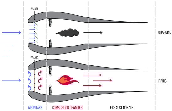
Figure 1.
Schematic of a valved pulsejet engine, based on [10].
2.2. Operation of Pulsejet Engines
Pulsejet engines operate in a cyclic manner, consisting of three main stages, as shown in Figure 2. In the first stage (marked as 1), air, symbolized by blue arrows, is drawn into the combustion chamber through the intake valves. At the same time, fuel is injected, which mixes with the air to form a combustible mixture. At the appropriate moment, this mixture ignites, causing rapid combustion and a pressure increase inside the chamber.
In the second stage (marked as 2), the sudden expansion of the exhaust gases generates high pressure, which closes the intake valves, visible as black lines at the intake. The exhaust gases are expelled through the exhaust nozzle, generating thrust, symbolized by the orange arrow [11]. The high temperature and pressure lead to the expulsion of gases at high velocity, which propels the engine.
In the third stage (marked as 3), the expansion of the exhaust gases causes a temporary vacuum in the combustion chamber. This results in the reopening of the valves and the intake of fresh air into the engine. The process can start anew, ensuring the cyclic operation of the unit [11].

Figure 2.
Schematic of a valved pulsejet engine operation [12].
2.3. Methods of Controlling a Pulsejet Engine
2.3.1. Valved Pulsejet Engines
In pulsejet engines equipped with valves, the combustion process is controlled by regulating the air intake into the combustion chamber. The most commonly used solution is mechanical valves, which open and close in rhythm with the engine’s operation under the influence of pressure changes. At the moment of combustion of the fuel–air mixture, the rapidly increasing pressure causes the valve to automatically close, preventing the gases from flowing back through the intake. Then, when the exhaust gases are expelled through the exhaust nozzle, a vacuum is created in the chamber, which reopens the valve and allows a new portion of air to be drawn in. This cycle repeats several dozen times per second, giving the engine its characteristic pulsating mode of operation.
However, the use of a mechanical valve has its drawbacks. During intense engine operation, the valve components are exposed to extreme temperatures and rapid opening and closing cycles, leading to their rapid wear and even the risk of damage. Additionally, mechanical valves have a specific response time, which can lead to so-called backflow, where some of the exhaust gases flow back into the air intake instead of being effectively expelled through the exhaust nozzle. This phenomenon is particularly undesirable at low flow velocities, as it reduces the engine’s efficiency. To prevent this, special diaphragm valves are used, which operate on the principle of a one-way throttle. The diaphragm allows free airflow into the combustion chamber but closes under the pressure of the exhaust gases, preventing them from flowing back.
An alternative solution is the use of electronic control of the intake valves, which allows for more precise management of the opening and closing moments. Electronically controlled valves can improve engine efficiency by optimizing the operating cycle, but their use requires the introduction of additional control elements, which increases the complexity and weight of the propulsion system [11,13].
2.3.2. Valveless Pulsejet Engines
The second category of pulsejet engines is valveless designs (valveless pulsejet engines), which do not use any moving parts to regulate airflow. The control of the combustion process is based solely on the appropriately designed geometry of the combustion chamber and the intake and exhaust channels. During the combustion of the fuel–air mixture, the resulting high pressure expels the gases mainly through the exhaust nozzle, but some of the gases also flow back through the intake channel. Then, after the gases are expelled, the pressure in the chamber drops below atmospheric pressure, causing the automatic intake of fresh air and the initiation of another combustion cycle.
Although in theory some of the exhaust energy “escapes” through the air intake, in practice, this does not mean a significant loss of thrust. By using appropriate design solutions, such as curving the intake channels or building the engine in a “U” shape (Figure 3), it is possible to effectively direct both gas streams in the same direction, increasing the efficiency of the propulsion. The valveless design eliminates the problems associated with mechanical wear of the valves, making such engines more durable and reliable. Additionally, the lack of moving parts allows for significant simplification of the design and reduction in weight, which is crucial in military applications, especially in drones and jet missiles [14].
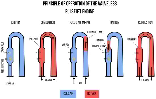
Figure 3.
Schematic of a valveless pulsejet engine in a “U” shape [15].
Despite numerous advantages, valveless pulsejet engines also have their limitations. Their efficiency is generally lower than that of valved engines, as they do not have a precise mechanism for controlling the flow of air and exhaust gases. Additionally, valveless pulsejet engines require careful tuning of the combustion chamber shape and the length of the intake and exhaust channels to achieve optimal performance.
3. Types of Alternative Fuels
3.1. Synthetic Fuels and Biofuels
Synthetic fuels, also known as e-fuels, are produced in chemical processes from non-fossil raw materials, such as biomass, carbon dioxide, and hydrogen, using renewable energy. These are liquid or gaseous fuels that can be used in existing engines and fuel infrastructure, making them an attractive alternative in sectors that are difficult to decarbonize, such as aviation, maritime transport, and heavy road transport.
Synthetic fuels can be produced from various raw materials using the following technologies:
- Power-to-Liquid (PtL) fuels—produced in a process that uses renewable energy to convert water and carbon dioxide into liquid fuels. Among PtL fuels, synthetic gasoline, synthetic diesel, and aviation fuels are distinguished. This process allows for the production of high-purity fuels that can be used in pulsejet engines without the need for modification. Importantly, the use of CO2 as a raw material means that the emissions generated during fuel combustion are offset by the absorption of this gas in the production process.
- Gas-to-Liquid (GtL) fuels—synthesized from natural gas or other gases. This group includes synthetic diesel, gasoline, and aviation fuels. GtL technology, based on the Fischer–Tropsch process, allows for the production of high-quality fuels with low impurity content. Due to the high efficiency of the process and its scalability, GtL fuels are an attractive solution for the automotive and aviation industries.
- Biomass to Liquid (BtL)—a technology in which biomass (e.g., wood, agricultural waste, straw) is converted into synthesis gas (syngas), which is then used as a raw material for the production of liquid fuels, such as synthetic diesel and aviation fuels, using the Fischer–Tropsch process [16].
Hydrogen-based fuels include substances such as methanol, synthetic natural gas, and dimethyl ether (DME). They are produced in chemical processes where hydrogen reacts with other compounds, such as carbon dioxide. Hydrogen, being a key raw material in these processes, can be obtained from renewable energy sources, which makes these fuels potentially capable of significantly reducing greenhouse gas emissions [16,17].
Biofuels, on the other hand, are renewable fuels produced from biological materials, such as vegetable oils, animal fats, or organic waste. They can be used in pure form or as additives to fossil fuels. Biofuels are characterized by biodegradability, low toxicity, and the ability to reduce greenhouse gas emissions due to their carbon neutrality.
Biofuels are generally divided into four generations depending on the raw material used:
- First generation—from food raw materials, such as sugars and fats,
- Second generation—obtained from agricultural waste,
- Third generation—produced from microalgae,
- Fourth generation—resulting from advanced biochemical processes [16].
3.2. Gaseous Fuels
3.2.1. Natural Gas
Natural gas can be stored as fuel in two forms: LNG (Liquefied Natural Gas) and CNG (Compressed Natural Gas). LNG is a mixture of methane and small amounts of ethane, propane, nitrogen, and other compounds, depending on the source of the natural gas. The structure of the fuel is shown in Table 1. Its boiling temperature usually ranges from −166 °C to −157 °C at atmospheric pressure, and its density ranges from 430 to 470 kg/m3 (depending on the composition). Therefore, to liquefy natural gas, it must be cooled to approximately −162 °C. In this state, the gas becomes a liquid and reduces its volume by 600 times, making it more advantageous for storage. LNG is a very good alternative to diesel fuel [18].
The introduction of LNG as an alternative fuel has brought many environmental benefits. These include clean combustion, which results in almost 99% fewer particulate emissions, sulfur oxides, about 80% fewer nitrogen oxides, and about 20% less carbon dioxide compared to diesel fuel. Vehicles powered by LNG also produce lower noise levels [19].

Table 1.
Structure of methane [20].
Table 1.
Structure of methane [20].
| Name | Compound | Structure |
|---|---|---|
| Methane | CH4 |  |
3.2.2. Liquefied Petroleum Gas (LPG)
LPG, or liquefied petroleum gas, is a mixture of hydrocarbons consisting mainly of propane and butane, with small amounts of propylene and butylene; the structural diagram is included in Table 2. In many cases, the properties of propane, which dominate the composition, are taken as an approximate characteristic of LPG. Natural gas (CNG) and LPG differ significantly in composition. LPG contains primarily propane (about 57%) and butane (about 41%), while natural gas consists mainly of methane, accounting for over 80% of its composition [21].
Table 2.
Composition and structure of LPG [20,21].
LPG is produced as a by-product of two main processes:
- Natural gas processing: During the production of natural gas, methane and other light hydrocarbons are released. The separation process takes place in gas processing plants, where, under conditions of elevated pressure and reduced temperature, liquid components such as propane and butane are recovered.
- Oil refining: LPG is produced during oil refining, particularly in processes such as hydrocracking, which allow for the transformation of the molecular structure of hydrocarbons into more desirable fuel products.
Globally, about 60% of LPG comes from natural gas processing, and the remaining 40% from oil refining [22]. LPG in liquid form has an energy density 270 times greater than in gaseous form, making its storage and transport practical and economical. LPG can be stored in tanks under moderate pressure, making it easier to use in vehicles compared to natural gas.
Vehicles powered by LPG emit significantly fewer harmful exhaust components than those powered by gasoline or diesel. LPG, due to its lower carbon-to-hydrogen ratio, higher octane number, and ability to form a homogeneous mixture in the combustion chamber, allows for the reduction in harmful emissions [21,22].
3.2.3. Biogas/Biomethane
Biogas, also known as biomethane or Renewable Natural Gas (RNG), is gaining increasing importance as one of the key alternative fuels due to its renewable nature, environmental friendliness, and ability to effectively utilize organic waste. It is produced through the anaerobic decomposition of biological and animal waste [23].
Biogas consists mainly of three compounds: methane, carbon dioxide, and nitrogen, but may also contain trace amounts of hydrogen sulfide, hydrogen, ammonia, oxygen, and carbon monoxide. The structural scheme of biogas is shown in Table 3. Additionally, typical biogas is saturated with water, dust particles, siloxanes, aromatic compounds, and halogenated compounds. The calorific value of biogas can be determined by the percentage content of these components [23,24,25].
Table 3.
Composition and structure of biogas [20,24].
Combustion systems adapted to operate on biogas contribute to combating global warming by burning methane from organic waste instead of allowing it to escape into the atmosphere, where it contributes to the greenhouse effect. Biogas may also contain small amounts of reactive substances, such as hydrogen sulfide (H2S, 1 to 5%) and hydrogen (H2, 0 to 1%). These components can increase the flammability and propagation of the biogas flame. Purified biogas, due to its properties and versatility, finds applications in various fields. It can be used to generate electricity, heat, and steam, which is beneficial for both households and industry [24,26].
3.2.4. Ethyne/Acetylene
Ethyne, also known as acetylene, is the simplest compound in the group of unsaturated hydrocarbons, with the structure shown in Table 4. It is one of the potential alternative fuels that can be used in internal combustion engines. Pure ethyne is odorless, but it usually contains impurities with sulfur and phosphorus compounds (mainly phosphine, PH3 and hydrogen sulfide, H2S), giving it a specific odor. It is characterized by high flammability and the ability to generate very high combustion temperatures, reaching up to 3000 °C. It has a relatively low autoignition temperature, and its calorific value is comparable to that of diesel fuel [27].
Table 4.
Structure of ethyne [20,27].
This fuel can be effectively used in diesel engines in dual-fuel mode, where ethyne is supplied to the intake system, and diesel fuel acts as the ignition fuel. In such conditions, ethyne contributes to reducing diesel fuel consumption and CO2 emissions. Previous studies have also shown that ethyne, in combination with oxidizing fuels such as ethanol or diethyl ether, can significantly improve engine efficiency and reduce harmful emissions [27,28].
Ethyne can be produced simply through the hydrolysis reaction of calcium carbide with water, making it relatively inexpensive to produce and readily available. In the context of sustainable development, the production of ethyne from biomass can further reduce the carbon footprint associated with its production. This process involves the pyrolysis of biomass, the production of calcium carbide (CaC2), and the recycling of lime, leading to lower CO2 emissions compared to traditional coal-based methods [29].
However, ethyne also has some drawbacks, such as high flammability, which requires special precautions during storage and transport. Additionally, ethyne can lead to increased emissions of nitrogen oxides (NOₓ) if the combustion parameters are not properly selected [28,30].
3.3. Liquid Fuels
3.3.1. Biodiesel
Biodiesel is a renewable alternative fuel produced from plant or animal fats, mainly through the transesterification process. This results in fatty acid methyl esters (FAMEs), which can be used as a substitute or additive to conventional diesel fuel (e.g., in proportions of B5, B20, or B100—practically pure methyl or ethyl ester). Alternatively, biodiesel can be produced in the form of Hydrotreated Vegetable Oil (HVO), which improves its chemical stability and combustion properties [21].
Various plant oils, such as soybean, rapeseed, sunflower, palm, and jatropha seed oils, as well as animal fats and used cooking oils, are used to produce biodiesel. Biodiesel from plant oils is characterized by a high cetane number (46–60, depending on the raw material), ensuring better ignition properties. Saturated oils, such as animal fats, have a higher cetane number than polyunsaturated oils, such as soybean oil. Biodiesel contains oxygen, which reduces its calorific value (about 37–39 MJ/kg) compared to conventional diesel but improves its lubricating properties, leading to reduced wear of fuel system components [22].
Biodiesel can be used as a standalone fuel (B100) or in blends with diesel fuel (e.g., B5, B20). In Europe, the EN 14214 standard specifies the minimum ester content (96.5% by mass) and the maximum content of methanol, glycerides, and glycerin. In the USA, the ASTM D975 standard allows for a biodiesel content of up to 5% (B5) in conventional diesel fuel, and ASTM D7467 regulates blends of B6–B20 [22].
Biodiesel also significantly reduces emissions of particulate matter and carbon monoxide compared to fossil fuels. However, the combustion of biodiesel leads to increased emissions of nitrogen oxides (NOₓ), requiring the use of appropriate emission reduction systems [22].
Due to its high compatibility with existing fuel infrastructure and diesel engines, biodiesel finds applications in road transport, agriculture, and energy. Its production based on renewable raw materials allows for a reduction in greenhouse gas emissions, making it an essential element in the decarbonization of the fuel industry [22].
3.3.2. Alcohol-Based Fuels
Alcohol-based fuels, such as ethanol, methanol, and butanol, are gaining importance as alternative energy sources for internal combustion engines. Alcohols have higher boiling points and enthalpies of vaporization compared to hydrocarbons of similar molecular weight. This characteristic contributes to their ability to cool the air charge in the combustion chamber, increasing resistance to knocking and allowing for higher thermal efficiency in internal combustion engines [21]. The most commonly used alcohols for pulsed propulsion are methanol and ethanol, whose structures are shown in Table 5.
Table 5.
Structure of methanol and ethanol [20,31].
The use of ethanol as an alternative fuel is increasing every year. As a fuel, almost pure ethanol (95% ethanol and 5% water) can be used, which, due to its low pressure and clean combustion properties, offers several environmental benefits. It can also be used as a blend with gasoline. This fuel is oxygenated (contains 35% oxygen), which reduces emissions of particulate matter, nitrogen oxides (NOₓ), carbon monoxide, and ozone formation, which is desirable under clean air regulations. Ethanol has about 2/3 the energy and calorific value of gasoline but provides more efficient combustion. Ethanol is a renewable energy source produced through the fermentation of sugars. A potential inexpensive source of ethanol production is the use of lignocellulosic materials, such as crop residues, grasses, sawdust, wood chips, animal manure, and industrial waste [31].
Methanol, although less popular than ethanol, offers similar benefits. It is cheaper to produce but more toxic, which limits its use compared to ethanol. Methanol has a lower energy density, requiring larger fuel quantities to achieve the same power. Its resistance to knocking makes it an attractive fuel for high-compression engines [32].
Butanol is an alcohol with more carbon atoms than ethanol or methanol, giving it a higher energy density and a stoichiometric value closer to that of gasoline. It can be used as a standalone fuel or as an additive, and its lower volatility reduces emissions compared to methanol and ethanol [32].
Alcohols can be used in spark-ignition engines as standalone fuels or in blends with gasoline. Their high octane number allows for increased compression in engines, leading to higher efficiency. Alcohol fuels also contribute to reducing emissions of particulate matter, nitrogen oxides (NOₓ), and hydrocarbons [32].
3.3.3. Sustainable Aviation Fuel (SAF)
Sustainable Aviation Fuel is a modern alternative fuel that is gaining increasing importance in the aviation sector. Produced from renewable raw materials such as biomass, plant oils, industrial waste, or through synthetic processes with CO2 and hydrogen, SAF offers significant environmental benefits [33].
SAF as an aviation fuel must have physicochemical properties that allow for its safe use, as specified in the international standards ASTM D1655 and D1655. These standards define requirements for criteria such as fuel composition, combustion, corrosion, thermal stability, and additives, as well as the permissible proportion in blends with conventional fuel. SAF is characterized by a calorific value similar to that of conventional aviation fuel Jet A-1, and its production and combustion lead to a reduction in CO2 emissions by up to 80% over the fuel’s life cycle. Additionally, it does not contain sulfur and has limitations on aromatic content, which reduces emissions of particulate matter and sulfur oxides during combustion. Currently, there are 7 technologies for producing SAF from biomass, alcohol, and other raw materials and 3 related to co-processing in conventional fuel refineries [34]. Approved production technologies are described in Table 6.
Life Cycle Assessment (LCA) is a key tool for evaluating the environmental impact of sustainable aviation fuels. LCA allows for a comprehensive assessment of greenhouse gas emissions at every stage of the fuel’s life cycle, from raw material extraction, through production and transport, to combustion in aircraft engines. In the case of SAF, LCA includes emissions related to the cultivation of raw materials (e.g., biomass), their processing, as well as emissions resulting from Induced Land Use Change (ILUC).
LCA values for different raw materials and SAF production technologies vary, reflecting differences in cultivation methods, transport, and processing of raw materials. For example, for the Fischer–Tropsch process (FT-SPK), the lowest LCA values are achieved for raw materials such as miscanthus, which is characterized by negative ILUC values, leading to a significant reduction in total emissions over the fuel’s life cycle. In the case of the HEFA process, which is the most commonly used technology for SAF production, the lowest LCA values are achieved for jatropha oil, which also has negative ILUC values. In contrast, for palm oil, LCA values are significantly higher due to high emissions associated with land-use change [35]. LCA analysis shows that SAF can significantly contribute to reducing GHG emissions in the aviation sector, especially when raw materials come from waste or are cultivated in a sustainable manner, minimizing environmental impact.
SAF is compatible with existing fuel infrastructure and aviation engines, allowing for its implementation without the need for technical modifications. Its use includes commercial and military aviation, and the development of production technologies enables increased production scale in the future. Sustainable aviation fuel is a key element in efforts to decarbonize the aviation sector and achieve climate neutrality goals.
Table 6.
Approved SAF production technologies [36].
Table 6.
Approved SAF production technologies [36].
| ASTM Reference | Conversion Process | Abbreviation | Possible Feedstocks | Max. Blend Ratio |
|---|---|---|---|---|
| ASTM D7566 Annex A1 | Fischer–Tropsch hydroprocessed synthesized paraffinic kerosene | FT | Coal, natural gas, biomass | 50% |
| ASTM D7566 Annex A2 | Synthesized paraffinic kerosene from hydroprocessed esters and fatty acids | HEFA | Vegetable oils, animal fats, and used cooking oils | 50% |
| ASTM D7566 Annex A3 | Synthesized iso-paraffins from hydroprocessed fermented sugars | SIP | Biomass used for sugar production | 10% |
| ASTM D7566 Annex A4 | Synthesized kerosene with aromatics derived by alkylation of light aromatics from non-petroleum sources | FT-SKA | Coal, natural gas, biomass | 50% |
| ASTM D7566 Annex A5 | Alcohol to jet synthetic paraffinic kerosene | ATJ-SPK | Ethanol, isobutanol, and isobutene from biomass | 50% |
| ASTM D7566 Annex A6 | Catalytic hydrothermolysis jet fuel | CHJ | Vegetable oils, animal fats, and used cooking oils | 50% |
| ASTM D7566 Annex A7 | Synthesized paraffinic kerosene from hydrocarbon—hydroprocessed esters and fatty acids | HC-HEFA-SPK | Algae | 10% |
| ASTM D7566 Annex A8 | Synthetic paraffinic kerosene with aromatics | ATJ-SKA | C2–C5 alcohols from biomass | - |
| ASTM D1655 Annex A1 | Co-hydroprocessing of esters and fatty acids in a conventional petroleum refinery | - | Vegetable oils, animal fats, and used cooking oils from biomass processed with petroleum | 5% |
| ASTM D1655 Annex A1 | Co-hydroprocessing of Fischer–Tropsch hydrocarbons in a conventional petroleum refinery | - | Fischer–Tropsch hydrocarbons co-processed with petroleum | 5% |
| ASTM D1655 Annex A1 | Co-processing of HEFA | - | Hydroprocessed esters/fatty acids from biomass | 10% |
4. Methodology and Results
4.1. Chemical Calculations
In a chemical context, combustion is a rapid exothermic reaction of fuel with oxygen. During the combustion process, a specific amount of energy is released, which can be calculated using Hess’s law. More precisely, Hess’s law allows the determination of the enthalpy of combustion. Hess’s law is expressed by the formula [37]:
where (kJ) represents the enthalpy of reaction, is the index representing the product, is the index representing the subtract, indicates the number of moles of product I, and is the number of moles of reactant . Moreover, the (kJ) is the standard enthalpy of formation of product and (kJ) symbolizes the standard enthalpy of formation of reactant . The term (kJ) is the sum of changes in standard enthalpy of the products, while (kJ) is the sum of changes in standard enthalpy of the subtract.
Based on the above law, it was established that the amount of heat released or absorbed by the system depends only on the initial and final states of the reaction, regardless of the reaction path. The enthalpy of combustion is expressed as the difference between the enthalpy of the products and the enthalpy of the reactants at a given temperature and pressure [38], i.e., it is the amount of energy in the form of heat released during the complete combustion of the fuel. This value is expressed in units of kJ/mol or kJ/kg.
The combustion energy of the individual fuels was calculated using Hess’s law-Equation (1), based on the standard enthalpy in Table 7, and the results are presented in Table 8. The enthalpy of combustion was calculated for 1 mole of fuel according to the stoichiometry of the given reaction, and the detailed calculations are provided in Appendix A.
Table 7.
Standard enthalpy values [39,40].
Table 7.
Standard enthalpy values [39,40].
Table 8.
Results of enthalpy of combustion calculations for fuels [41].
Table 8.
Results of enthalpy of combustion calculations for fuels [41].
| Calculated Enthalpy of Combustion [kJ] | ||||||||
|---|---|---|---|---|---|---|---|---|
| Natural Gas | LPG | Ethyne | Biogas | Biodiesel | Methanol | Ethanol | Jet A-1 | SAF |
Accurate enthalpy of combustion values may vary for individual fuels depending on the source, measurement method, and state of aggregation of the products [38]. The enthalpy of combustion allows for a theoretical analysis of the combustion value, and for practical determination, the heat of combustion is used, which refers to the total energy released during the combustion of a unit mass or volume and reflects the states of the combustion products [42].
The combustion of a given mixture is characterized by the maximum energy value during combustion , which is defined as follows:
where (kJ/kg) symbolizes maximum energy value during combustion, (kJ/kg) is the heat of combustion and indicates theoretical air requirement (kg air/kg fuel). Heat of combustion and theoretical air requirement values for each fuel are presented in Table 9, and the results of the calculations of maximum energy are presented in Table 10.
Table 9.
Heat of combustion and theoretical air requirement values for calculations [37,43,44,45].
Table 10.
Results of maximum energy value calculations during combustion.
Fuel requirement
To determine the fuel requirement, the mass of the fuel–air mixture for all the indicated fuels was analyzed. It was assumed that the amount of fuel in one cycle is 50 mg. The theoretical air requirement in relation to the fuel mass was taken into account in the calculations.
The relationship describing the mass of the fuel–air mixture is given by the formula:
where (mg) represents the mass of the mixture, (mg) is the mass of the fuel, and (mg) is the mass of air required for the combustion of the given amount of fuel [mg].
The mass of air was determined by the formula:
Calculations of the mixture mass for natural gas were performed:
Similar calculations were performed for each fuel, and the results are presented in Table 11.
Table 11.
Results of mixture mass calculations for one cycle.
4.2. Simulation of Combustion Effects
Based on the data presented in Section 4.1, simulations were conducted in Ansys 2025 software to analyze the emissions of environmentally impacting compounds (CO2, H2O, and CO) for various alternative fuels. The combustion simulations were performed in Ansys Fluent using a transient, pressure-based solver. The main simulation settings are summarized in Table 12. These parameters ensured both numerical stability and accuracy of the combustion simulation. The realizable k-ε turbulence model was used in conjunction with species transport and the finite-rate/eddy dissipation combustion model. For initialization, hybrid methods were selected due to their robustness across a wide range of flow conditions.
Table 12.
Main simulation settings for Ansys Fluent.
The results of these simulations are shown in Figure 4 and Figure 5. The simulations covered the following fuels: natural gas, LPG, biogas, methanol, ethanol, Jet A-1, and ethyne. Due to software limitations, simulations for biodiesel and SAF could not be performed.
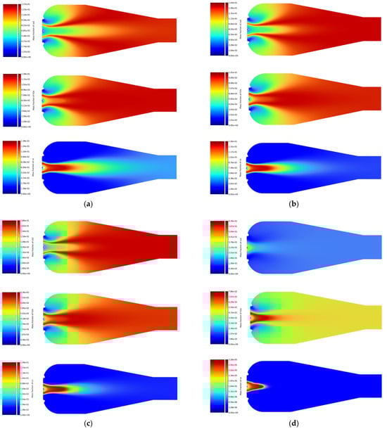
Figure 4.
Simulation results of CO2, H2O, and CO emissions for (a) natural gas, (b) LPG, (c) ethyne, and (d) biogas.
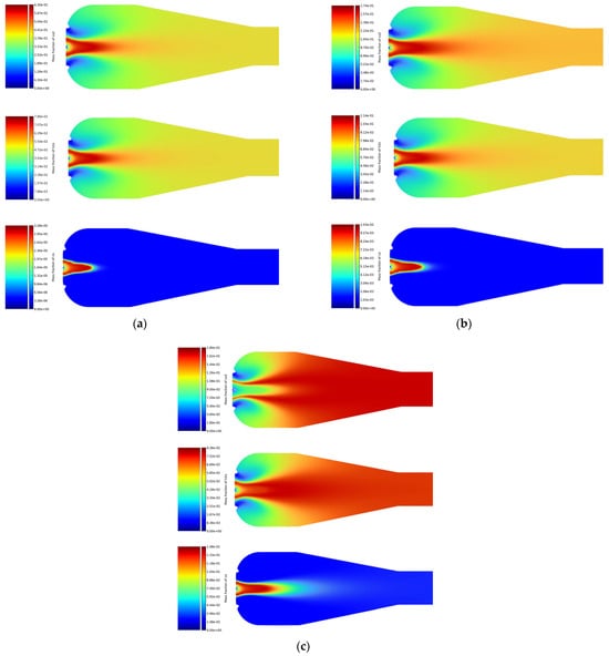
Figure 5.
Simulation results of CO2, H2O, and CO emissions for (a) methanol, (b) ethanol, and (c) Jet A-1.
For gaseous fuels, the emission distribution obtained from the simulations is shown in Figure 4. The highest CO2 emissions were obtained from the combustion simulations for biogas (Figure 4d), ranging from to . In contrast, the maximum CO2 emission value for ethyne (Figure 4c) was significantly lower, at . LPG (Figure 4b) achieved a CO2 emission value close to that of ethyne, at . The lowest result was obtained for natural gas (Figure 4a), at .
Biogas and ethyne had the highest emissions of water vapor (H2O), ranging from to , with biogas showing higher H2O emissions compared to ethyne. LPG and natural gas generated lower H2O emissions, ranging from to , with the lowest H2O emission recorded for natural gas, at .
In the simulations, biogas showed the lowest CO emission, with a maximum value of . Ethyne, LPG, and natural gas had significantly higher CO emissions, reaching values up to . High CO emissions for these fuels suggest that their combustion processes were not always complete, which could lead to the formation of CO as an intermediate product resulting from incomplete oxidation.
In the simulations performed for liquid fuels, shown in Figure 5, Jet A-1 (Figure 5c) achieved the highest CO2 emission value among liquid fuels, with a maximum value of . Ethanol (Figure 5b) showed lower CO2 emissions compared to Jet A-1, with a maximum value of . The lowest CO2 emission among liquid fuels was obtained for methanol (Figure 5a), at .
The results of H2O emissions showed that methanol had the highest emission among liquid fuels, with a maximum value of . Ethanol showed slightly lower H2O emissions, with a maximum value of , while Jet A-1 had the lowest maximum H2O emission value, at .
The results of CO emissions for liquid fuels showed that methanol and ethanol achieved maximum emission values of and , respectively. Jet A-1 showed higher CO emissions, at , indicating less efficient combustion compared to methanol and ethanol.
In summary, the simulations in Ansys software showed that biogas and methanol are characterized by the lowest CO2 emissions among the studied fuels, making them particularly attractive from the standpoint of environmental impact reduction and alignment with decarbonization goals. This supports their inclusion in further experimental campaigns aimed at sustainable propulsion strategies. Methanol’s combustion profile—yielding relatively low amounts of CO2—also reinforces its potential as a transitional fuel in UAV and auxiliary propulsion applications.
At the same time, the elevated CO emissions observed for ethyne, LPG, and natural gas point to incomplete or imbalanced combustion under the tested conditions, emphasizing the need to optimize air–fuel mixing, ignition timing, or equivalence ratio to minimize the formation of harmful intermediate products. These findings indicate that while gaseous fuels may have logistical or performance advantages, their emissions profiles must be carefully managed to ensure environmental compliance and safe operation.
For liquid fuels, particularly methanol and ethanol, the simulations revealed significantly lower CO2 emissions compared to conventional Jet A-1, confirming their value as more environmentally friendly alternatives. Additionally, their simpler chemical structures may contribute to cleaner combustion with fewer unburned hydrocarbons or particulates—factors increasingly relevant for future emissions standards. These results, while derived from controlled simulations, provide a strong rationale for continued development and eventual in-engine validation of selected fuels under real-world operating conditions.
5. Multi-Criteria Analysis of Selected Alternative Fuels
5.1. Multi-Criteria Analysis Methodology
A multi-criteria analysis was conducted using the zero-unitization method, which is one of the most commonly used normalization methods for diagnostic features in comparative studies. This method allows for the transformation of variables with different units and value ranges into a uniform scale, enabling their comparison and aggregation.
The zero-unitization method is based on transforming the original values of diagnostic variables into the interval (0, 1) [46]. These values are normalized based on the range of the variable, i.e., the difference between the maximum and minimum values of the variable.
The formulas for normalization are as follows:
- For stimulant variables, whose higher values are desirable:
- For destimulant variables, whose lower values are desirable:
- For nominant variables, whose specific values are desirable:
Summing all the normalized variables, an aggregate variable characterizing a given object is obtained. The influence of the data of individual criteria on the final result of the analysis was also taken into account by assigning them weights () with values of 0–1:
where indicates an aggregate variable for object , represents an aggregate variable for object , and is the weight of variable .
The assignment of weights () in the multi-criteria analysis, presented in Table 13, was based on a consensus among the seven authors of this study. Each author contributed their domain-specific expertise, including propulsion systems, environmental assessment, and fuel technology, to reflect a balanced and interdisciplinary perspective. While no external expert survey was conducted, the use of internal expert elicitation is a recognized and pragmatic approach in multi-criteria and sustainability-related studies, especially in emerging or interdisciplinary fields.
Table 13.
Variables used in the analysis and their weights.
The literature emphasizes the critical role of expert participation in multi-criteria evaluations, highlighting that their judgment enhances both the credibility and applicability of the outcomes [47]. The use of small expert panels has been validated in the literature as an effective and commonly accepted practice. Dua et al. [48] argued that engaging a small but diverse group of experts can yield valuable insights—provided that transparent criteria and rigorous evaluation methods are used. They cite literature that supports the validity of even relatively small expert panels (approximately 10–20 individuals) in horizon scanning and trend identification exercises. Similarly, Wei et al. [49], in applications of hybrid MCDM (Multiple-Criteria Decision-Making) models, and Tseng et al. [50], in the context of Delphi surveys and technology evaluations, emphasized that expert-based judgement—even with sample sizes of 5–10—is appropriate when methodological transparency and internal consistency are maintained.
Therefore, leveraging the collective expertise of the seven co-authors falls well within accepted academic practice and offers a balanced, internally consistent basis for the weight assignment process used in this study.
The calorific value, fuel production costs, thermal expansion, and LCA values were determined based on literature analysis. Emissions were determined based on the simulations presented in Section 4.2. The REC parameter, which indicates the percentage of energy in the fuel derived from renewable sources, was calculated based on the formula:
where:
—percentage of renewable fuel in the blend [%],
—calorific value of renewable fuel [kJ/kg],
—percentage of conventional fuel in the blend [%],
—calorific value of conventional fuel [kJ/kg].
5.2. Results of the Analysis
The analysis was conducted based on data obtained from research studies, literature, and fuel manufacturers, as presented in Table 14. The table provides an overview of various fuel properties, which serve as the foundation for the zero-unitization method to obtain data for the multi-criteria analysis.
Table 14.
Input data for multi-criteria analysis [29,35,39,51,52,53,54,55,56,57,58,59,60,61,62,63,64].
The multi-criteria analysis of the potential of alternative fuels used in pulsejet engines is presented using the aggregate variable in Table 15.
Table 15.
Aggregate variable values for selected fuels.
Example calculations for biodiesel:
- —caloric value:
- —CO2 emissions:
Combustion reaction of methyl oleate:
C19H36O2 + 27O2→19CO2 + 18H2O
Molar mass C19H36O2: 296 g/mol
Molar mass CO2: 44 g/mol
From 1 mole C19H36O2, 19 moles CO2 are produced,
i.e., from 296 g C19H36O2, 836 g CO2 are produced
CO2 emission per unit mass of fuel:
CO2 [g/kg] = 836,296 × 1000 ≈ 2824 g/kg
- —aggregate variable:
During the study, an assessment of the potential of various alternative fuels in terms of their use in pulsejet engines was conducted. The results of the analysis presented in Table 15 indicate that biogas and methanol have the highest potential in the context of sustainable development, with the highest aggregate variable values of 0.789 for biogas and 0.790 for methanol. This indicates their significant potential in the context of sustainable development. Biogas is characterized by low CO2 emissions and the possibility of production from organic waste, while methanol is distinguished by high energy efficiency and low production costs.
For natural gas and LPG, the calculated aggregate variable values were 0.740 and 0.681, respectively, mainly due to their low emissions compared to conventional fuels. However, their dependence on fossil raw materials limits their long-term attractiveness, especially in the context of achieving climate neutrality. Additionally, the low density of these fuels is associated with additional difficulties in storage and transport, which can affect their practicality in certain applications.
The aggregate variable for biodiesel was 0.575, indicating a moderate potential for this fuel. Biodiesel, despite its biodegradability and the possibility of production from renewable sources, is characterized by higher emissions of nitrogen oxides compared to other alternative fuels, which affects its overall assessment.
For the second of the alcohol-based fuels studied, ethanol, the aggregate variable value was 0.730. This alternative fuel is characterized by low CO2 emissions and the possibility of production from biomass, making it attractive in terms of reducing greenhouse gas emissions. However, its lower calorific value compared to other fuels may limit its use in certain cases.
The aggregate variable for SAF has a value of 0.721. A key feature of these alternative fuels dedicated to the aviation sector is the reduction in emissions throughout the life cycle. However, their production costs are still significantly higher than those of other conventional fuel alternatives. Additionally, their maximum proportion in blends with Jet A-1 is 50%, which means that to achieve a meaningful result, data for a 50% blend with Jet A-1 with a result of 0.591 must be considered, reducing its final potential as an alternative fuel.
The least favorable result in the multi-criteria analysis was obtained for ethyne, with an aggregate variable value of 0.503. This is mainly due to its high CO2 emissions and significantly higher production costs compared to other alternative fuels. Additionally, ethyne is characterized by high flammability, requiring special precautions during storage and transport.
6. Discussion
6.1. Fuel Availability and LCA Limitations
A key consideration emerging from this multi-criteria analysis is the real-world availability of the proposed fuels and their life-cycle costs. Many alternative fuels face constraints in production scalability and economic viability. For example, producing second-generation biofuels from lignocellulosic feedstock or microalgae can be highly energy- and cost-intensive [65].
Microalgae-derived biogas illustrates this point. While microalgae offer extremely high biomass yields per hectare and do not compete with food crops, the processes to cultivate algae and convert them to fuel remain expensive and not yet widely commercialized [26]. More broadly, many bio-jet fuels require additional refining steps beyond those for first-generation biofuels like ethanol or biodiesel, leading to higher projected costs per unit energy. Indeed, even approved alternative jet fuels today tend to be in short supply and costly compared to fossil fuels.
These limitations mean that a high multi-criteria analysis ranking for a fuel must be contextualized by its supply chain maturity; a top-ranked fuel may still face bottlenecks in feedstock sourcing or prohibitive life-cycle processing costs. Fuel choices for pulsejet UAVs cannot ignore production realities: The promise of sustainable fuels like algal biogas or synthetic e-fuels will only be realized if production methods advance to deliver adequate quantities at acceptable cost and environmental footprint.
Furthermore, the emissions behavior of a given fuel in a pulsejet engine depends not only on its chemical composition but also on local combustion conditions. For instance, NOₓ emissions are strongly influenced by peak flame temperatures and residence time in high-temperature zones—conditions that may arise more readily with certain fuels or at high equivalence ratios. Similarly, carbon monoxide levels are often elevated under fuel-rich conditions or in zones with incomplete mixing and poor turbulence. Turbulence intensity, inlet pressure, and fuel atomization characteristics all influence local stoichiometry and the completeness of combustion. These effects are particularly relevant in pulsejets, where the combustion cycle is unsteady and mixing is dominated by acoustic and vortex interactions. Therefore, the observed emissions are not solely a property of the fuel, but also of how it behaves under dynamic flow and thermal conditions in the engine geometry.
This interaction between fuel chemistry, supply-chain viability, and combustion behavior underscores the need for integrated assessments—such as the one presented here—that account for both the potential and the practical constraints of each fuel pathway.
6.2. Implications for Experimental Validation and Engine Development
The present analysis, alongside prior studies on multi-fuel propulsion systems, contributed directly to the formulation of a broader research concept aimed at practical validation. As a result, a prototype of a pulsejet engine is currently under development, designed with flexibility in mind rather than optimized for a single fuel. This platform is intended to serve not only as a demonstrator but also as a testbed for combustion modelling and emissions validation.
The criteria and fuel characteristics explored in the current study, as well as the combustion parameters, such as velocity gradient, heat release rate, and dynamic pressure, presented in the article regarding the concept of multi-fuel pulsejet engine [66], played an important role in defining the engine’s key parameters. They contribute to the selection of parameters such as ignition method, combustion chamber dimensions, and air–fuel mixing strategy, so as to accommodate a range of fuel types, from alcohols to gas-phase mixtures. Focusing on the top-performing fuels allows targeted experiments to verify the predicted performance (thrust, specific fuel consumption, emissions) under real operating conditions.
Such validation is crucial because it will reveal phenomena that simulations or theoretical scoring cannot fully capture—e.g., ignition reliability, transient throttle response, or flame stability with each fuel. Moreover, by concentrating on a few promising fuels, the experimental program can delve deeper into optimization (such as adjusting ignition systems or injection timing for a given fuel’s properties). Ongoing engine development is explicitly aimed at a flexible pulsejet that can operate on multiple fuels [66], and the present analysis steers this development toward the most viable options. In effect, the multi-criteria analysis results act as a decision aid, ensuring that subsequent prototyping efforts and resources are aligned with fuel choices that offer the best balance of performance, sustainability, and feasibility. Ultimately, this tight coupling between analytical ranking and hands-on testing will accelerate the refinement of the engine and build confidence in the chosen fuel(s) for operational use.
6.3. Simulation Constraints and Result Comparability
It is also important to discuss the limitations of the computational approach used in this study, as they affect how results are compared across fuels. Modern CFD tools like Ansys Fluent have significantly expanded our ability to simulate pulsejet combustion and predict performance metrics. In this work, we successfully modeled several fuels (e.g., methane, methanol, ethanol, and LPG) using detailed combustion simulations. However, we encountered specific challenges in modeling SAF and biodiesel. These fuels are complex mixtures (SAF often being a blend of various hydrocarbons, and biodiesel consisting of long-chain methyl esters), for which Fluent does not provide combustion models. As a result, we could not include SAF and biodiesel in the CFD simulations.
To ensure full comparability across all fuels within the multi-criteria analysis, we estimated the carbon dioxide emissions for SAF and biodiesel based on their theoretical chemical composition, assuming complete combustion under stoichiometric conditions. This approach enabled consistent categorization and normalization of all fuel candidates, allowing them to be assessed using the same methodology. Substituting simulation-based results with literature-derived emission data for SAF and biodiesel would have introduced significant inconsistency, as those values would reflect different engine geometries, operating conditions, or boundary assumptions. Therefore, using a chemically derived estimation allowed these fuels to be evaluated on equal footing with those modeled in Fluent, without distorting the ranking due to incompatible computational baselines.
6.4. Practical Integration Challenges for UAV Application
Beyond performance metrics and rankings, practical integration of any new fuel into a UAV pulsejet system demands careful consideration of operational factors. Our analysis, combined with literature observations, highlights several challenges that must be addressed before an alternative fuel can be deemed truly viable for use in the field. Key integration concerns include the following:
- Combustion stability: Different fuels exhibit different combustion behaviors in a pulsejet. For example, biogas with a low methane content can have difficulty sustaining stable combustion—in detonation engine tests, methane concentrations below about 60–65% severely hindered the ability to maintain detonations [26]. Maintaining stable periodic combustion is critical not only for performance but also to avoid damaging backfires. Thus, each fuel’s combustion characteristics must be matched with engine tuning to preserve smooth operation.
- Engine wear and materials compatibility: The choice of fuel can significantly impact engine longevity and maintenance. Methanol is a case in point—it is known to be corrosive to common engine metals and has almost no lubricating properties, which can accelerate wear on moving parts like fuel pumps, injectors, and valves [67]. Biogas, on the other hand, often contains impurities such as hydrogen sulfide, which can corrode engine internals and form deposits [24]. Running the engine on fuels that burn hotter or produce different pressure pulses could exacerbate these stresses. Therefore, integrating alternative fuels may require upgrading material selections.
- Fuel storage: UAV’s fuel must be carried on board, and the form of the fuel drastically influences the aircraft’s design and logistics. Fuels like biogas present a storage challenge—in raw form, biogas has low energy density and must be either compressed to high pressures or liquefied at cryogenic temperatures to carry useful amounts, which would require heavy tanks and complex support systems. This runs counter to the size and weight constraints of typical UAVs. Methanol is a liquid fuel and thus easier to handle than a gas, but it contains only about half the energy per liter of gasoline.
- Logistics footprint: Field operations would need a supply chain for methanol or biomethane. Unlike standard jet fuel or gasoline, which are readily available globally, methanol and especially biogas may not be available at forward bases or may require on-site production facilities. Handling procedures also differ—methanol is toxic and requires protective measures, while compressed gases need special safety protocols. These logistic and infrastructural factors mean that even if a fuel performs well in the engine, the overall system feasibility for UAV deployment could be compromised.
- UAV platform compatibility: Each fuel’s characteristics can influence the UAV platform design. A pulsejet running on a different fuel might alter the thermal profile of the exhaust (e.g., flame temperature and radiant heat), potentially requiring changes to shielding or tail design to avoid heat damage to the airframe. Exhaust products could affect the UAV’s infrared or visible signature, which is a consideration for military or stealth applications. The fueling system components must be compatible with the fuel’s chemical nature.
- Noise emission: One of the inherent drawbacks of pulsejet propulsion is the very high level of noise generated due to the cyclical combustion process and unsteady exhaust flow. The fuel type can further influence the intensity and frequency spectrum of the emitted noise, especially through changes in combustion pressure, exhaust gas temperature, and detonation frequency. For UAV applications, particularly those requiring stealth or civilian operation, high acoustic output may be unacceptable. While all pulsejet engines are noisy by nature, selecting and tuning fuels that promote smoother combustion profiles could contribute to modest reductions in noise. However, more research is needed in this area, as no standardized acoustic profiles exist yet for pulsejets running on alternative fuels.
6.5. Guiding Future Research and UAV Propulsion Optimization
Finally, we reflect on how the outcomes of this study steer future research directions and the optimization of UAV propulsion systems. The multi-criteria fuel ranking provides a strategic perspective on alternative pulsejet fuels by balancing performance, environmental, and practical factors. This kind of holistic assessment is valuable for decision-makers and researchers alike. For example, our results may highlight a particular fuel (or a small subset of fuels) as having an attractive overall profile—these become strong candidates for further R&D investment.
Results of the analysis could act as a roadmap for optimizing the propulsion system. Knowing which fuel is preferred allows engineers to tailor the engine design and control strategy to that fuel’s characteristics. For instance, if methanol is chosen as the optimal fuel, efforts can be made to adjust the engine’s compression, intake geometry, and electronic control (FADEC) specifically to maximize methanol combustion efficiency and throttle response. This targeted optimization is already being seen in emerging pulsejet developments—e.g., Wave Engine Corp’s pulsejet UAVs use digital control to achieve surprisingly competitive fuel efficiency on alternative fuels [68].
In light of these challenges, it is clear that a fuel’s high ranking in the multi-criteria analysis does not automatically translate to an easy drop-in solution. The multi-criteria approach intentionally includes practical criteria (like safety, availability, etc.) to penalize fuels that are impractical, but some issues only manifest at the integration stage. Our discussion here serves to acknowledge those and to outline the scope of what additional work is needed when transitioning from analysis to deployment. The outcome of this study is thus not a final judgement but a starting point to identify where to focus the engineering effort.
7. Summary and Conclusions
The transition to alternative fuels is a key step toward achieving global sustainable development goals, particularly in sectors heavily dependent on fossil fuels, such as aviation. Pulsejet engines, despite their limitations, can serve as a platform for testing and implementing these fuels due to their simplicity and flexibility. This study highlights the environmental and operational benefits of various alternative fuels, providing a basis for future research and development in this area.
Alternative fuels such as biogas, methanol, biodiesel, and SAF offer significant environmental benefits, including reduced greenhouse gas and pollutant emissions. The results of the multi-criteria analysis indicate that biogas and methanol are the most promising alternative fuels in terms of sustainable development and emissions reduction. Other fuels, such as natural gas, LPG, biodiesel, ethanol, and SAF, can also have a positive environmental impact, but their use is limited by factors such as production costs, harmful emissions, and technical challenges related to storage and transport. Ethyne, due to its high CO2 emissions and costs, remains the least attractive solution among the studied fuels.
Methanol and ethanol, as alcohol-based fuels, show particularly low emissions of pollutants, making them attractive alternatives in terms of reducing environmental impact. Jet A-1, despite higher CO2 emissions, remains an important fuel in aviation, but its environmental impact can be reduced by blending it with alternative fuels such as SAF. Currently, their use is limited by standards and a maximum permissible concentration in blends of 50%.
However, the implementation of alternative fuels in pulsejet engines is associated with certain challenges. Key issues include increasing the efficiency of pulsejet engines, optimizing combustion processes to minimize harmful emissions such as nitrogen oxides (NOₓ) and carbon monoxide (CO), and reducing the noise generated by pulsejet engines, which is particularly important in civilian applications.
The development of synthetic fuel production technologies and their integration with existing fuel infrastructure are crucial for achieving climate neutrality goals. Synthetic fuels produced from renewable energy sources can significantly reduce CO2 emissions in the aviation sector and other transport sectors. However, their production costs remain high, requiring further investment in research and development of alternative fuels.
Furthermore, the current study demonstrates how theoretical evaluations—when carefully normalized and interpreted—can serve as a useful tool for early-stage fuel selection, guiding both simulation strategies and experimental efforts. The integration of multi-criteria analysis with emission simulations provides insight not only into environmental priorities but also into the operational trade-offs important for UAV propulsion systems, such as fuel logistics, combustion stability, and platform compatibility. These considerations are crucial for practical integration, especially in autonomous or tactical UAVs, where modularity and fuel flexibility are essential.
Importantly, this theoretical framework contributed directly to the concept and preliminary design of a new multi-fuel pulsejet engine prototype, currently under construction. The engine is intended to validate the presented models and rankings in real-world conditions, thus creating a feedback loop between simulation and experiment. These efforts underline the potential for pulsejet platforms not only to serve niche propulsion roles but also as research tools to accelerate the testing and optimization of sustainable fuels.
In summary, alternative fuels and pulsejet engines have significant potential in reducing greenhouse gas emissions and improving energy efficiency. However, their full implementation requires further research, investment, and political support to address challenges related to production costs, efficiency, and noise reduction. In particular, fuels such as methanol and biogas show promising results in emission simulations, making them attractive alternatives to conventional fuels for further development and use in pulsejet engines.
Author Contributions
Conceptualization, G.M.S.; Methodology, K.S. and M.K.; Formal analysis, G.M.S., B.W., M.N. and A.S.; Investigation, K.S.; Resources, M.N.; Data curation, M.K.; Writing—original draft, G.M.S., K.S., M.K., M.N., A.L. and A.S.; Writing—review & editing, G.M.S., B.W., K.S., A.L. and A.S.; Visualization, M.K.; Supervision, G.M.S. and B.W.; Project administration, K.S. All authors have read and agreed to the published version of the manuscript.
Funding
This research received no external funding.
Data Availability Statement
Data is contained within the article.
Acknowledgments
This work was supported by the Research Subsidy SBAD 0416/SBAD/0007 and the Research Subsidy 09/11/SBAD/2405 in the year 2025.
Conflicts of Interest
The authors declare no conflict of interest.
Appendix A
To support the comparative analysis of alternative fuels presented in the main body of the manuscript, this appendix provides detailed thermodynamic calculations of the combustion enthalpy based on stoichiometric combustion reactions for each fuel under standard conditions, assuming complete oxidation.
- Natural gas
- LPG
For LPG, which is a mixture of propane and butane gases, the enthalpy of combustion is determined by separate calculations for each compound, and then the value for the mixture is estimated based on the percentage composition.
Combustion of propane:
Combustion of butane:
The mixture of propane and butane is used in different proportions, so for the calculations, it was assumed that the gases are equally 50%.
- Biogas
To accurately calculate the enthalpy of combustion of biogas, it is necessary to analyze its composition because the enthalpy of combustion directly depends on the methane (CH4) content. Assume an example composition of biogas: 60% CH4, 40% CO2, and standard combustion conditions. The enthalpy of combustion of pure biogas would be equal to the enthalpy of combustion of methane, i.e., −802.38 kJ [41]. Taking into account the percentage composition of the fuel, the enthalpy of combustion of biogas was calculated:
- Ethyne
- Biodiesel
Biodiesel is mainly composed of fatty acid methyl esters. For the calculations, methyl oleate was assumed as the ester present in biodiesel. The enthalpy value of methyl oleate was estimated based on average chemical bond energies [69]. Accurate enthalpy of combustion values may vary depending on the source and measurement method.
- Methanol
- Ethanol
- SAF
Similarly, for LPG, aviation fuels are mixtures of compounds. For the analysis, Jet A-1 fuel, consisting of 50.25% n-hexadecane, 44.78% decalin, and 4.97% toluene, and SAF fuel, consisting of 38.8% dodecane, 52.1% isooctane, and 9.1% propylbenzene, were selected. First, the enthalpy of combustion of the individual compounds was determined, and then the enthalpy of combustion was calculated based on the percentage composition [70].
Combustion of Jet A-1:
Combustion of SAF:
References
- Bradley, D.; Cheng, R.K.; Dunn-Rankin, D.; Evans, R.L.; Keller, J.; Levinsky, H.; Mcdonell, V.; Miyasato, M.M.; Pham, T.K.; Schefer, R.W.; et al. Lean Combustion; Dunn-Rankin, D., Ed.; Academic Press: Cambridge, MA, USA, 2008. [Google Scholar]
- Advisory Group for Aerospace Research & Development. Combustion and Fuels in Gas Turbine Engines: Papers Presented at the Propulsion and Energetics Panel 70th Symposium Held in Chania; Advisory Group for Aerospace Research & Development: Neuilly-sur-Seine, France, 1988; ISBN 9283504658. [Google Scholar]
- RAND Corporation. Pulsejet Engines for UAVs: Flight-Proven Drone Propulsion Systems. Available online: https://www.unmannedsystemstechnology.com/company/wave-engine-corporation/ (accessed on 6 December 2024).
- Johnson, R.G. Design, Characterization, and Performance of a Valveless Pulse Detonation Engine. Ph.D. Thesis, Naval Postgraduate School, Monterey, CA, USA, 2000. [Google Scholar]
- Xu, B.; Kolosz, B.W.; Andresen, J.M.; Ouenniche, J.; Greening, P.; Chang, T.S.; Maroto-Valer, M.M. Performance Evaluation of Alternative Jet Fuels Using a Hybrid MCDA Method. Energy Procedia 2019, 158, 1110–1115. [Google Scholar] [CrossRef]
- Kraviarová, D.; Janošovský, J.; Variny, M. Multi-Criteria Evaluation of Environmentally Friendly Alternative Fuels †. Eng. Proc. 2024, 64, 11. [Google Scholar] [CrossRef]
- Boichenko, S.; Bavykin, O.; Artyukhov, A.; Bogacki, S.; Rutkowski, M.; Reśko, D. Progress and Prospects of Sustainable Aviation Fuel Implementation: A Critical Analysis, Challenges and Conclusions. Energies 2025, 18, 3154. [Google Scholar] [CrossRef]
- Okolie, J.A.; Awotoye, D.; Tabat, M.E.; Okoye, P.U.; Epelle, E.I.; Ogbaga, C.C.; Güleç, F.; Oboirien, B. Multi-Criteria Decision Analysis for the Evaluation and Screening of Sustainable Aviation Fuel Production Pathways. iScience 2023, 26, 106944. [Google Scholar] [CrossRef] [PubMed]
- Candel, S.; Durox, D.; Ducruix, S.; Birbaud, A.-L.; Noiray, N.; Schuller, T. Flame Dynamics and Combustion Noise: Progress and Challenges. Int. J. Aeroacoust. 2009, 8, 1–56. [Google Scholar] [CrossRef]
- JetX Engineering Introduction. Available online: https://www.jet-x.org/a1.html?fbclid=IwZXh0bgNhZW0CMTEAAR3nBwaeDVhqSxktIan78of7V8Du4gh5jZ3DEzBLWGTnBpM9yin3nuK0hl8_aem_ZJqkhlLV0qYUUg4hvHhFOg (accessed on 20 February 2025).
- Ghulam, M.M.; Muralidharan, S.S.; Anand, V.; Prisell, E.; Gutmark, E.J. Operational Mechanism of Valved-Pulsejet Engines. Aerosp. Sci. Technol. 2024, 148, 109060. [Google Scholar] [CrossRef]
- Phipps, C. The Jet Plane: How Metal Birds Fly. In No Wonder You Wonder! Springer International Publishing: Cham, Switzerland, 2016. [Google Scholar] [CrossRef]
- Garnier, E.; Leplat, M.; Monnier, J.-C.; Delva, J. Flow Control by Pulsed Jet in A Highly Bended S-Duct. In Proceedings of the 6th AIAA Flow Control Conference, New Orleans, LA, USA, 25–28 June 2012; ISBN 978-1-62410-188-5. [Google Scholar] [CrossRef]
- Sarvotham Yadav, G.; Dixit, A.; Sai Abhishek, G.; Sawan Kumar, G. Experimental Studies on a Valveless Pulsejet Engine. 2012. Available online: https://www.researchgate.net/publication/366759940_Experimental_studies_on_a_valveless_pulsejet_engine?channel=doi&linkId=63b1b0dfc3c99660ebbefbc5&showFulltext=true (accessed on 6 December 2024).
- Subramanian, M.; Venkatesh, N.; Gopikannan, S.; Kavin, V.; Harish, V. Estimation of Mechanical Properties of Water Agumented Pulse Jet Engine. Int. J. Adv. Res. 2020, 8, 747–755. [Google Scholar] [CrossRef]
- Ram, V.; Salkuti, S.R. An Overview of Major Synthetic Fuels. Energies 2023, 16, 2834. [Google Scholar] [CrossRef]
- Styring, P.; Dowson, G.R.M.; Tozer, I.O. Synthetic Fuels Based on Dimethyl Ether as a Future Non-Fossil Fuel for Road Transport From Sustainable Feedstocks. Front. Energy Res. 2021, 9, 663331. [Google Scholar] [CrossRef]
- Bernatik, A.; Senovsky, P.; Pitt, M. LNG as a Potential Alternative Fuel—Safety and Security of Storage Facilities. J. Loss Prev. Process Ind. 2011, 24, 19–24. [Google Scholar] [CrossRef]
- Pfoser, S.; Schauer, O.; Costa, Y. Acceptance of LNG as an Alternative Fuel: Determinants and Policy Implications. Energy Policy 2018, 120, 259–267. [Google Scholar] [CrossRef]
- National Center for Biotechnology Information PubChem Open Chemistry Database. Available online: https://pubchem.ncbi.nlm.nih.gov/ (accessed on 5 February 2025).
- Turner, J.W.G.; Leach, F.C.P. Using Alternative and Renewable Liquid Fuels to Improve the Environmental Performance of Internal Combustion Engines: Key Challenges and Blending Technologies. In Alternative Fuels and Advanced Vehicle Technologies for Improved Environmental Performance: Towards Zero Carbon Transportation, 2nd ed.; Woodhead Publishing Series in Energy; Woodhead Publishing: Sawston, UK, 2022; pp. 57–92. [Google Scholar] [CrossRef]
- Martins, J.; Brito, F.P. Alternative Fuels for Internal Combustion Engines. Energies 2020, 13, 4086. [Google Scholar] [CrossRef]
- Mihic, S. Biogas Fuel for Internal Combustion Engines. Ann. Fac. Eng. Hunedoara 2004, 2, 179–190. [Google Scholar]
- Ullah Khan, I.; Hafiz Dzarfan Othman, M.; Hashim, H.; Matsuura, T.; Ismail, A.F.; Rezaei-DashtArzhandi, M.; Wan Azelee, I. Biogas as a Renewable Energy Fuel—A Review of Biogas Upgrading, Utilisation and Storage. Energy Convers. Manag. 2017, 150, 277–294. [Google Scholar] [CrossRef]
- Elhawary, S.; Saat, A.; Wahid, M.A.; Ghazali, A.D. Experimental Study of Using Biogas in Pulse Detonation Engine with Hydrogen Enrichment. Int. J. Hydrogen Energy 2020, 45, 15414–15424. [Google Scholar] [CrossRef]
- Warimani, M.; Azami, M.H.; Khan, S.A.; Ismail, A.F. Study of Feasibility of Pulse Detonation Engine Powered by Alternative Fuels. Int. J. Eng. Adv. Technol. 2019, 8, 291–296. [Google Scholar]
- Koli, S.R.; Hanumantha Rao, Y.V. Acetylene an Potential Alternative Fuel for Stationary Diesel Engine. Int. J. Recent. Technol. Eng. 2019, 8, 5013–5016. [Google Scholar] [CrossRef]
- Singh, G.; Sharma, S.; Singh, J.; Kumar, S.; Singh, Y.; Ahmadi, M.H.; Issakhov, A. Optimization of Performance, Combustion and Emission Characteristics of Acetylene Aspirated Diesel Engine with Oxygenated Fuels: An Experimental Approach. Energy Rep. 2021, 7, 1857–1874. [Google Scholar] [CrossRef]
- Jiang, P.; Zhao, G.; Zhang, H.; Ji, T.; Mu, L.; Lu, X.; Zhu, J. Towards Carbon Neutrality of Calcium Carbide-Based Acetylene Production with Sustainable Biomass Resources. Green Energy Environ. 2024, 9, 1068–1078. [Google Scholar] [CrossRef]
- Özer, S.; Akçay, M.; Vural, E.; Yilmaz, İ.T. The Effects of the Use of Acetylene Gas as an Alternative Fuel in a Gasoline Engine. Int. Adv. Res. Eng. J. 2020, 4, 76–86. [Google Scholar] [CrossRef]
- EBA Biomethane Fact Sheet. Available online: https://www.europeanbiogas.eu/wp-content/uploads/files/2013/10/eba_biomethane_factsheet.pdf (accessed on 5 December 2024).
- Łodygowski, K. Paliwa Syntetyczne Do Zasilania Silników Spalinowych z Zapłonem Samoczynnym. Tech. Transp. Szyn. 2013, 10, 655–663. [Google Scholar]
- IATA. Sustainable Aviation Fuel: Technical Certification. Available online: https://www.iata.org/contentassets/d13875e9ed784f75bac90f000760e998/saf-technical-certifications.pdf (accessed on 5 December 2024).
- CAAFI. Certification Pathways. Available online: https://www.caafi.org/fuel-qualifications (accessed on 5 December 2024).
- Kurzawska-Pietrowicz, P. Life Cycle Emission of Selected Sustainable Aviation Fuels—A Review. Transp. Res. Procedia 2023, 75, 77–85. [Google Scholar] [CrossRef]
- ICAO. SAF Conversion Process. Available online: https://www.icao.int/environmental-protection/GFAAF/Pages/Conversion-processes.aspx (accessed on 5 December 2024).
- Atkins, P.W.; Atkins, P.; Julio, P.; Keeler, J. Chemia Fizyczna; Wydawnictwo Naukowe PWN: Warsaw, Poland, 2022. [Google Scholar]
- Moran, M.J.; Shapiro, H.N. Fundamentals of Engineering Thermodynamics, Second Edition. Eur. J. Eng. Educ. 1993, 18, 215. [Google Scholar] [CrossRef]
- National Institute of Standards and Technology NIST. Chemistry WebBook. Available online: https://webbook.nist.gov (accessed on 4 January 2025).
- Rumble, R.J. Standard Thermodynamic Properties of Chemical Substances. In Handbook of Chemistry and Physics, 99th ed.; CRC Pr I LLC: Boca Raton, FL, USA, 2018. [Google Scholar]
- Vitázek, I.; Klúčik, J.; Uhrinová, D.; Mikulová, Z.; Mojžiš, M. Thermodynamics of Combustion Gases from Biogas. Res. Agric. Eng. 2016, 62, S8–S13. [Google Scholar] [CrossRef]
- Smith, J.M.; Van Ness, H.C.; Abbott, M.M.; Swihart, M.T. Introducion to Chemical Engineering Thermodynamics, 8th ed.; McGraw-Hill Education: New York, NY, USA, 2018. [Google Scholar]
- Shinde, S.; Yadav, S.D. Theoretical Properties Prediction of Diesel-Biodiesel-DEE Blend as a Fuel for C.I. Engine With Required Modifications for Optimum Performance. Int. J. Curr. Eng. Technol. 2016, 6, 1562–1567. [Google Scholar]
- Dimitrov, R.; Zlateva, P. Determination of the Optimal Air-Fuel Ratio for Upgraded Biogas Engine Operation. E3S Web Conf. 2021, 327, 02009. [Google Scholar] [CrossRef]
- Bester, N.; Yates, A. Assessment of the Operational Performance of Fischer-Tropsch Synthetic-Paraffinic Kerosene in a T63 Gas Turbine Compared to Conventional Jet A-1 Fuel. In Proceedings of the ASME Turbo Expo 2009: Power for Land, Sea, and Air, Orlando, FL, USA, 8–12 June 2009; Volume 2. [Google Scholar] [CrossRef]
- Kukuła, K. Metoda Unitaryzacji Zerowanej Na Tle Wybranych Metod Normowania Cech Diagnostycznych. Acta Sci. Acad. Ostroviensis 1999, 4, 5–31. [Google Scholar]
- Govindan, K.; Kannan, D.; Jørgensen, T.B.; Nielsen, T.S. Supply Chain 4.0 Performance Measurement: A Systematic Literature Review, Framework Development, and Empirical Evidence. Transp. Res. E Logist. Transp. Rev. 2022, 164, 102725. [Google Scholar] [CrossRef]
- Dua, R.; Guzman, A.F. A Perspective on Emerging Energy Policy and Economic Research Agenda for Enabling Aviation Climate Action. Energy Res. Soc. Sci. 2024, 117, 103725. [Google Scholar] [CrossRef]
- Wei, C.C.; Tai, C.C.; Lee, S.C.; Chang, M.L. Assessing Knowledge Quality Using Fuzzy MCDM Model. Mathematics 2023, 11, 3673. [Google Scholar] [CrossRef]
- Tseng, C.C.; Zeng, J.Y.; Hsieh, M.L.; Hsu, C.H. Analysis of Innovation Drivers of New and Old Kinetic Energy Conversion Using a Hybrid Multiple-Criteria Decision-Making Model in the Post-COVID-19 Era: A Chinese Case. Mathematics 2022, 10, 3755. [Google Scholar] [CrossRef]
- Mi, Y.; Zheng, D.; Jiang, X. Multi-Product Carbon Footprint Assessment for Low-Rank Coal-Based Acetylene Manufacturing Process. J. Clean. Prod. 2016, 112, 1676–1682. [Google Scholar] [CrossRef]
- Zhang, S.; Li, J.; Li, G.; Nie, Y.; Qiang, L.; Bai, B.; Ma, X. Life Cycle Assessment of Acetylene Production from Calcium Carbide and Methane in China. J. Clean. Prod. 2021, 322, 129055. [Google Scholar] [CrossRef]
- Reyes, Y.A.; Tamayo, Y.E.; Garciga, J.P.; Barrera, E.L. Environmental Assessment of Acetylene Production Process via Calcium Carbide: A Case Study in Sancti Spíritus. Afinidad 2022, 80, 51–59. [Google Scholar] [CrossRef]
- Müller-Langer, F.; Dögnitz, N.; Marquardt, C.; Zschocke, A.; Schripp, T.; Oehmichen, K.; Majer, S.; Bullerdiek, N.; Halling, A.M.; Posselt, D.; et al. Multiblend JET A-1 in Practice: Results of an R&D Project on Synthetic Paraffinic Kerosenes. Chem. Eng. Technol. 2020, 43, 1514–1521. [Google Scholar] [CrossRef]
- Prussi, M.; Lee, U.; Wang, M.; Malina, R.; Valin, H.; Taheripour, F.; Velarde, C.; Staples, M.D.; Lonza, L.; Hileman, J.I. CORSIA: The First Internationally Adopted Approach to Calculate Life-Cycle GHG Emissions for Aviation Fuels. Renew. Sustain. Energy Rev. 2021, 150, 111398. [Google Scholar] [CrossRef]
- Khojasteh-Salkuyeh, Y.; Ashrafi, O.; Mostafavi, E.; Navarri, P. CO2utilization for Methanol Production; Part I: Process Design and Life Cycle GHG Assessment of Different Pathways. J. CO2 Util. 2021, 50, 101608. [Google Scholar] [CrossRef]
- Jeswani, H.K.; Chilvers, A.; Azapagic, A. Environmental Sustainability of Biofuels: A Review: Environmental Sustainability of Biofuels. Proc. R. Soc. A Math. Phys. Eng. Sci. 2020, 476, 20200351. [Google Scholar]
- Lyng, K.A.; Brekke, A. Environmental Life Cycle Assessment of Biogas as a Fuel for Transport Compared with Alternative Fuels. Energies 2019, 12, 532. [Google Scholar] [CrossRef]
- Rogowska, D.; Wyrwa, A. Analysis of the Potential for Reducing Life Cycle Greenhouse Gas Emissions from Motor Fuels. Energies 2021, 14, 3744. [Google Scholar] [CrossRef]
- Arteconi, A.; Brandoni, C.; Evangelista, D.; Polonara, F. Life-Cycle Greenhouse Gas Analysis of LNG as a Heavy Vehicle Fuel in Europe. Appl. Energy 2010, 87, 2005–2013. [Google Scholar] [CrossRef]
- Liu, F.; Shafique, M.; Luo, X. Literature Review on Life Cycle Assessment of Transportation Alternative Fuels. Environ. Technol. Innov. 2023, 32, 103343. [Google Scholar] [CrossRef]
- Schuller, O.; Kupferschmid, S.; Whitehouse, S.; Hengstler, J. Life Cycle GHG Emission Study on the Use of LNG as Marine Fuel. Report 2019, 40–154. [Google Scholar]
- Kang, H.S.; Lee, D.H.; Kim, K.T.; Jo, S.; Pyun, S.; Song, Y.H.; Yu, S. Methane to Acetylene Conversion by Employing Cost-Effective Low-Temperature Arc. Fuel Process. Technol. 2016, 148, 209–216. [Google Scholar] [CrossRef]
- Zhang, M.; Ma, J.; Su, B.; Wen, G.; Yang, Q.; Ren, Q. Pyrolysis of Polyolefins Using Rotating Arc Plasma Technology for Production of Acetylene. Energies 2017, 10, 513. [Google Scholar] [CrossRef]
- Murphy, J.D.; Drosg, B.; AllEn, E.; Jerney, J.; Xia, A.; Herrmann, C. A Perspective on Algal Biogas; IEA Bioenergy: Paris, France, 2015. [Google Scholar]
- Szymański, G.M.; Wyrwas, B.; Klekowicki, M.; Strugarek, K.; Nowak, M.; Ludwiczak, A.; Szymańska, A. Simulation Research of the Feasibility of Developing a Multi-Fuel Valved Pulsejet Engine. Combust. Engines 2025, 201, 91–102. [Google Scholar] [CrossRef]
- Infineum International Limited Unlocking the Full Potential of Methanol. Available online: https://www.infineuminsight.com/en-gb/articles/unlocking-the-full-potential-of-methanol/#:~:text=Methanol%20lubricity%20and%20corrosion%20challenges (accessed on 13 June 2025).
- Wave Engine Discover Wave Engine Technology. Available online: https://wave-engine.com/technology/ (accessed on 13 June 2025).
- Tankov, I.; Mustafa, Z.; Nikolova, R.; Veli, A.; Yankova, R. Biodiesel (Methyl oleate) Synthesis in the Presence of Pyridinium and Aminotriazolium Acidic Ionic Liquids: Kinetic, Thermodynamic Studies. Fuel 2022, 307, 121876. [Google Scholar] [CrossRef]
- Tian, B.; Liu, A.; Chong, C.T.; Fan, L.; Ni, S.; Hull, A.; Hull, A.; Rigopoulos, S.; Luo, K.H.; Hochgreb, S. Measurement and Simulation of Sooting Characteristics by an ATJ-SKA Biojet Fuel and Blends with Jet A-1 Fuel in Laminar Non-Premixed Flames. Combust. Flame 2021, 233, 111582. [Google Scholar] [CrossRef]
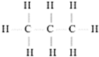
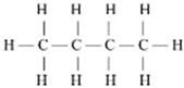
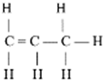
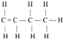

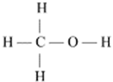
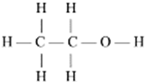
Disclaimer/Publisher’s Note: The statements, opinions and data contained in all publications are solely those of the individual author(s) and contributor(s) and not of MDPI and/or the editor(s). MDPI and/or the editor(s) disclaim responsibility for any injury to people or property resulting from any ideas, methods, instructions or products referred to in the content. |
© 2025 by the authors. Licensee MDPI, Basel, Switzerland. This article is an open access article distributed under the terms and conditions of the Creative Commons Attribution (CC BY) license (https://creativecommons.org/licenses/by/4.0/).