Article

A Comparative Study of Direct Power Control Strategies for STATCOM Using Three-Level and Five-Level Diode-Clamped Inverters

by
Diyaa Mustaf Mohammed
1,*,
Raaed Faleh Hassan
1,
Naseer M. Yasin
1,
Mohammed Alruwaili
2,* and
Moustafa Ahmed Ibrahim
3,*
1
Electrical Engineering Technical College, Middle Technical University, Baghdad 10074, Iraq
2
Department of Electrical Engineering, College of Engineering, Northern Border University, Arar 73213, Saudi Arabia
3
Electrical Engineering Department, University of Business and Technology, Jeddah 23435, Saudi Arabia
*
Authors to whom correspondence should be addressed.
Energies 2025, 18(13), 3582; https://doi.org/10.3390/en18133582
Submission received: 25 May 2025 / Revised: 25 June 2025 / Accepted: 4 July 2025 / Published: 7 July 2025

Abstract

For power electronic interfaces, Direct Power Control (DPC) has emerged as a leading control technique, especially in applications such as synchronous motors, induction motors, and other electric drives; renewable energy sources (such as photovoltaic inverters and wind turbines); and converters that are grid-connected, such as Virtual Synchronous Generator (VSG) and Static Compensator (STATCOM) configurations. DPC accomplishes several significant goals by avoiding the inner current control loops and doing away with coordinating transformations. The application of STATCOM based on three- and five-level diode-clamped inverters is covered in this work. The study checks the abilities of DPC during power control adjustments during diverse grid operation scenarios while detailing how multilevel inverters affect system stability and power reliability. Proportional Integral (PI) controllers are used to control active and reactive power levels as part of the control approach. This study shows that combining DPC with Sinusoidal Pulse Width Modulation (SPWM) increases the system’s overall electromagnetic performance and control accuracy. The performance of STATCOM systems in power distribution and transient response under realistic operating conditions is assessed using simulation tools applied to three-level and five-level inverter topologies. In addition to providing improved voltage quality and accurate reactive power control, the five-level inverter structure surpasses other topologies by maintaining a total harmonic distortion (THD) below 5%, according to the main findings. The three-level inverter operates efficiently under typical grid conditions because of its straightforward design, which uses less processing power and computational complexity.

1. Introduction

The modern power system requires advanced power converters, which guarantee efficient energy management as well as stability and power quality performance. Voltage Source Converters (VSCs) function as essential power electronic converters that provide fundamental characteristics to Flexible AC Transmission Systems (FACTS) and renewable energy interfaces and industrial drives. Power electronic devices require adaptive controller systems which control harmonic distortion and regulate reactive power together with sustaining near-unity power factor operation when experiencing varying grid conditions [1,2]. The STATCOM stands as a leading FACTS device that offers rapid voltage stabilization together with reactive power compensation, particularly in situations involving load transients [3,4]. DPC represents a state-of-the-art VSC control technique that offers a simple design structure along with unrivaled dynamic response speed while eliminating current loops inside the control system [5,6]. The regulation of the active and reactive power through DPC uses hysteresis comparators together with switching tables or advanced modulation techniques that include SPWM [7,8] instead of vector control methods with multiple transformation stages. The control method achieves enhanced transient performance, reduces THD, and improves EMI filter design [9,10]. Standard implementations of DPC encounter issues due to fluctuating switching frequencies because these issues worsen harmonic output while making electromagnetic interfere (EMI) filtering more complicated [11].
DPC offers several benefits: The algorithm for calculating voltage and active power is quite simple. It uses the estimated line voltage and applies compensations for unbalanced and distorted line voltage to shape the current waveforms into sinusoidal form. There is no need for coordinating transformation. However, using a lookup table for DPC has the following disadvantages:
  • When the variable switching frequencies are introduced, the harmonics within the system appear, making the designing process of the input EMI filter more challenging.
  • In the presence of some changes in the sector, the current in the source inductance, as well as the voltage at the DC link, may experience distortions.
To overcome the drawbacks of conventional DPC, such as variable switching frequency and EMI filter complexity, SPWM is integrated into the control scheme. SPWM offers a constant switching frequency, which simplifies filter design and enhances electromagnetic compatibility. Unlike Space Vector Modulation (SVM), which is computationally intensive and less suitable for real-time implementations in multilevel systems, SPWM provides a simpler and more hardware-friendly solution. In multilevel inverters, SPWM enables accurate voltage synthesis across multiple levels while maintaining low total harmonic distortion (THD). When combined with DPC, SPWM enhances power quality by ensuring smoother voltage transitions and stable inverter operation under dynamic grid conditions. This makes it a practical and efficient modulation choice for real-time control of three- and five-level diode-clamped inverters.
Current technological developments in multilevel inverter topologies, especially those that use diode-clamped (neutral-point-clamped) configurations, have decreased total harmonic distortion (THD), increased efficiency for medium- and high-voltage power conversion applications, and greatly improved voltage-balancing performance. The implementation of three-level inverters brings affordable medium-voltage solutions to the market, but five-level inverters enable superior harmonic reduction combined with improved voltage control [12,13]. Current multilevel inverter implementations face three main limitations, which include complexity constraints, unbalanced capacitor voltage characteristics, and grid instability [14,15]. Level-up inverters need precise measurements together with robust algorithms combined with increased computational demand, which acts as a barrier to real-time operation when grids experience instability [16,17]. In contrast to the more adaptable but computationally demanding MPC approach [18], DPC provides a quick dynamic response, although its performance under distorted voltage situations is still largely undocumented [19,20]. Recent developments in Direct Power Control aim to overcome its sensitivity to distorted or unbalanced grid voltages through intelligent and adaptive techniques. For example, Neural-Network-based DPC (NN-DPC) methods have been proposed to minimize harmonic distortion and power loss in wind energy conversion systems [21]. Similarly, Fuzzy Logic-based DPC techniques have been shown to reduce power ripples and improve dynamic performance in multilevel inverter applications [22,23]. Such approaches represent a significant evolution over the classical DPC structure and are becoming increasingly relevant in modern grid environments [24]. The comparison of DPC to MPC technology demonstrates essential performance limitations between the two systems. DPC maintains easy implementation for three-level inverters yet faces limitations when used with five-level systems because switching-state numbers grow exponentially. The predictive framework of MPC provides natural topology flexibility while requiring high-speed processing power, resulting in increased costs according to [25]. The combination of SPWM with DPC maintains the THD threshold of IEEE 519 (<5%), but MPC proves better at unbalanced grids through real-time harmonic optimization [26]. The combination of hybrid SPWM technology from DPC provides reduced complex systems, which deliver near-MPC operational performance suitable for economic power grids. The main operational restriction of this technology resides in its voltage sensitivity together with its high computational requirements for controllers operating at various voltage levels. This research performs an extensive evaluation of STATCOM DPC control methods through an analysis of three-level and five-level inverters that employ diode-clamped technology. The objectives are threefold: The research evaluates how the operational efficiency, harmonic performance, and dynamic response behave in both inverter configurations as they deal with dynamic loading situations. The analysis examines DPC restrictions, which consist of processing requirements and grid asymmetry sensitivity. A mixed DPC-SPWM approach is proposed for improving system scalability together with power quality standards under real-time operating conditions. While prior research [27,28,29,30,31,32] has validated DPC implementations for individual multilevel topologies, a critical gap exists in systematic comparative evaluations of three-level versus five-level diode-clamped inverters operated under identical DPC-SPWM control schemes. This study bridges this gap by rigorously analyzing both configurations under unified test conditions, addressing their cost–performance–complexity trade-offs in dynamic grid scenarios—an aspect underexplored in existing literature [33]. While advanced DPC variants such as neural-network-based and adaptive control strategies exist in the literature [34], this study focuses on a conventional DPC-SPWM framework to enable a fair and controlled comparison between three-level and five-level inverter topologies. Recent advances in Direct Power Control (DPC) for multilevel inverters have included adaptive techniques, such as sliding mode predictive control, to improve system robustness and dynamic performance. These methods enhance power quality and ensure stability under varying grid and load conditions, offering improved transient behavior compared to conventional DPC approaches [35]. A (1 + PI) control strategy has been proposed to effectively mitigate power ripples in variable-speed dual-rotor wind energy systems using DPC, enhancing system stability under fluctuating conditions [36]. Moreover, neural PI controllers integrated with modified four-level Space Vector Modulation (SVM) have shown improved tracking performance and reduced harmonic content in DFIG-based wind turbine systems [37]. In grid-connected PV applications, point of common coupling (PCC) voltage modulation-based DPC has been utilized to enhance power flow regulation and suppress distortions [38]. Additionally, a novel PCC-based DPC scheme has been introduced for renewable energy sources to improve overall power quality and ensure reliable grid integration under diverse operating scenarios [39]. This study makes theoretical contributions through numerical assessment of the cost–performance complexity relationships associated with inverters. Among the alternative control strategies to (DPC), the Proportional-Resonant (PR) controller has attracted increasing attention due to its ability to precisely track sinusoidal references without steady-state error. This makes it particularly well suited for AC systems, such as grid-connected inverters and STATCOMs. PR controllers offer improved performance over traditional PI controllers in terms of harmonic suppression and dynamic response at the fundamental frequency. Recent developments in PR control include adaptive frequency-tuned resonant structures and harmonic compensators that enable better performance under distorted grid conditions and nonlinear loads.
While conventional Proportional-Resonant (PR) controllers are known to require precise tuning around the fundamental frequency—making them potentially sensitive to frequency deviations in weak or non-ideal grids—recent advances have substantially overcome this limitation. Adaptive PR control techniques, including those based on non-Foster-inspired circuit design and dynamically tuned switched-capacitor structures, have expanded the operational bandwidth and robustness of PR controllers under variable-frequency conditions. These methods enable accurate reference tracking and harmonic compensation even in grids subject to significant frequency disturbances [40,41]. As such, adaptive PR controllers now represent a highly competitive solution for AC applications including grid-tied inverters and STATCOM systems. Furthermore, when extended to multi-resonant designs to compensate for multiple harmonics, the computational complexity and implementation effort increase considerably. Stability analysis and controller robustness become more challenging in such cases, particularly when integrated into high-order systems like multilevel inverters. The latest developments in multilevel STATCOM control demonstrate a range of different technical approaches. For example, MPC [17] is especially suited to uneven grid situations, yet the processors needed are costly, so they are not commonly used on a large scale. By contrast, using a hybrid DPC-SPWM method [20] allows THD below 5%, but these operations are still sensitive to changes in voltage. The comparison conducted here is different, as it involves systematically comparing three-level and five-level diode-clamped inverters while they are operated under the same DPC-SPWM mode. During sudden load changes, the results show improvement over the dynamic response measured in [22,25] while keeping both performance and costs in mind. The research demonstrates how five-level inverters achieve THD levels below 5% that meet IEEE 519 standards when operating under transient events. The research demonstrates how five-level inverters achieve THD levels below 5% that meet IEEE 519 standards when operating under transient events.

2. Direct Power Control (DPC)

Direct Power Control (DPC) has emerged as a powerful and efficient strategy to control VSCs, especially when there is an expected requirement to balance active and reactive power [42,43].
In traditional DPC architecture, as shown in Figure 1, the reactive power reference is usually provided by external control mechanisms specifically designed for reactive power regulation, whereas the active power reference is obtained from a DC-bus voltage control loop. Hysteresis comparators compare the difference between the reference signals and the computed feedback power estimates. A special feature of DPC is the complete absence of internal current control loops and other classic PWM modulators. However, a preestablished switching table or SPWM determines the switching states of the converter. The first difference between the instructed and predicted values of active and reactive power determines the switching states of the converter.
Incorporating instantaneous active and reactive power comparators into an SPWM framework significantly improves the performance of the original DPC technique, allowing for more accurate and reliable switching decisions [44]. This method provides enhanced precision in comparison to the lookup table technique, allowing for active power regulation control of varying amounts of reactive power to give zero value so that a unity power factor operation is achieved with efficient stabilization of the DC-bus voltage. The enhanced control method described in this paper offers proper systematic control of the system dynamic with simplicity along with accurate power control of the VSC driven systems. The function of PWM in VSC-driven systems has a prominent importance in VSC’s functional improvement, and these VSCs have been enhanced in terms of power quality and converter performance [45]. Notable techniques such as SPWM and Space Vector PWM (SVPWM) are extensively utilized because of their capacity to lower the amount of power loss due to [46]. Such advancements underscore the necessity of PWM to minimize harmonics and improve energy conversion efficiency in high-power applications. The efficiency of the DPC-based control of VSC systems is improved by the integration of real-time power comparators with SPWM. This lays the groundwork for more reliable and efficient power electronics solutions.

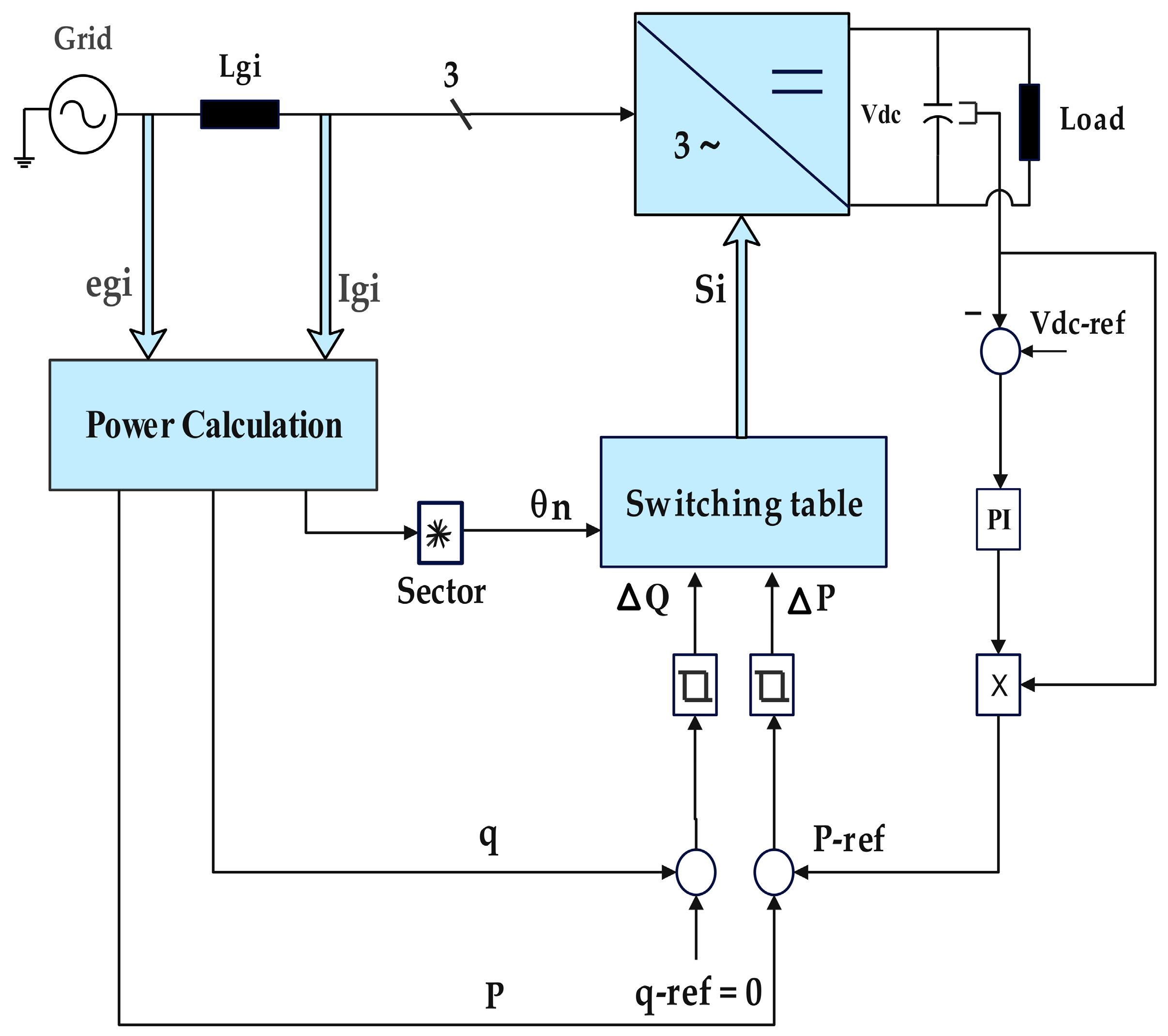
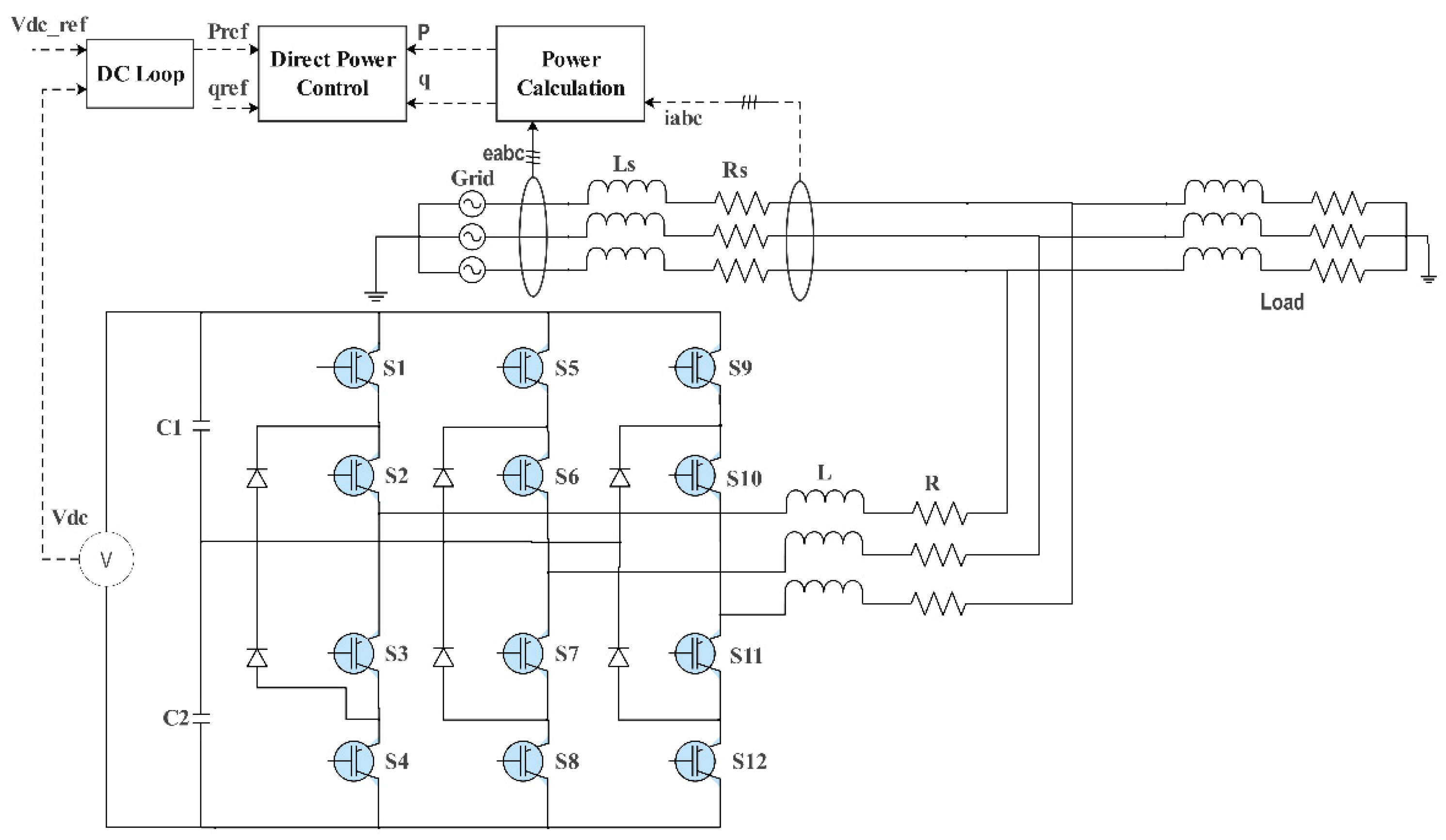
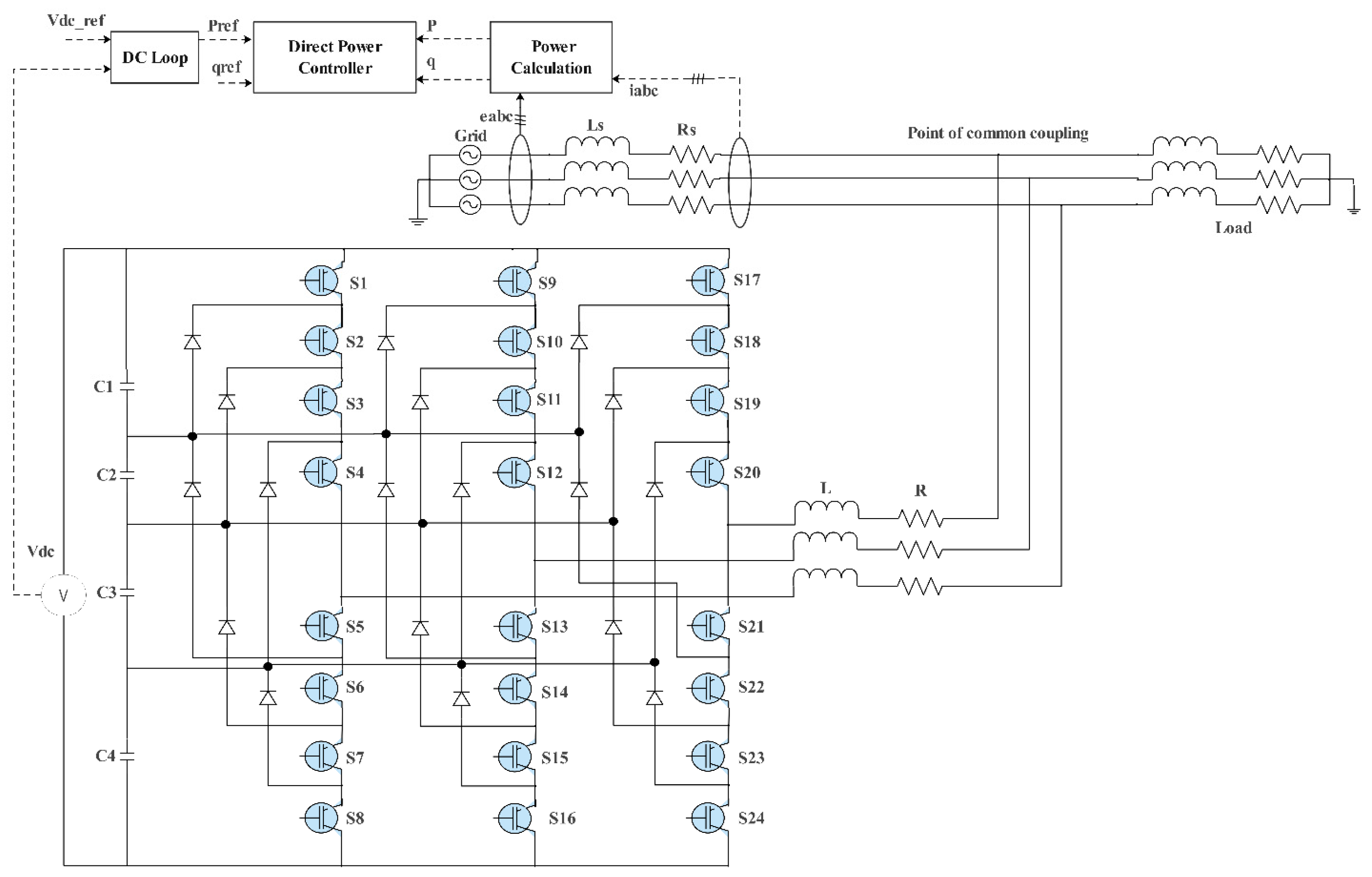
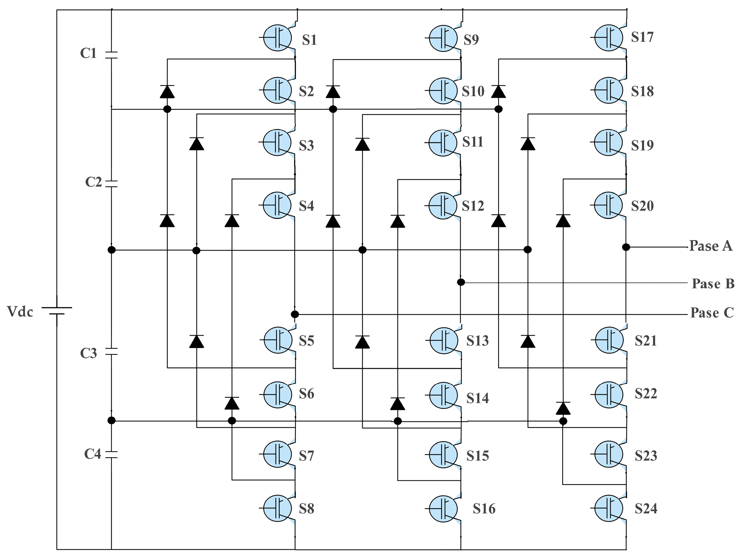
3. System Configuration

Figure 2 illustrates a DPC scheme for a three-level inverter functioning as a STATCOM. The system consists of a three-level inverter (diode-clamped topology) that uses IGBTs and clamping diodes and divides the DC-link voltage into two equal parts using capacitors (C1 and C2) [47]. The DC Voltage Control Loop maintains the DC-link voltage (Vdc) at the reference level ( V d c _ r e f ), DPC regulates the active power (P) and reactive power (Q) by selecting appropriate switching states for the inverter, and the Power Calculation Block computes the active and reactive power using grid voltage ( e _ a b c ) and measured current ( i _ a b c ).
Figure 3 displays a three-phase, three-level type of diode-clamped inverter (NPC). As was observed in Figure 3, each of the phases of the inverter share a common DC-link supply. The midpoints of the different steps are joined successively with one another to a point that is common. The load is three-phase AC-powered with the inverter supplying it. The three levels of output are −Vdc, 0, and +Vdc which depend on the value of the DC-bus voltage. On the switches (Si1 Si4) and (Si2 Si3), there should be complementarities to the converter so as to have the desirable three-level voltages in the letter i, which symbolizes the phase indicator (i = a, b, c). Figure 3 is i-phase switching with switching states, as indicated in Table 1, with the associated levels of output voltage.
The modulation technique used in the three-level configuration is Phase Disposition (PD) [48]. To generate a sinusoidal PWM signal, a sine wave is provided as a reference signal. Although advanced PWM techniques such as SVPWM and DPWM provide better switching performance in multilevel converters [49,50], PD-SPWM was chosen in this study to maintain control simplicity and ensure identical modulation conditions for both three-level and five-level systems. Future extensions will incorporate SVPWM and DPWM benchmarking to evaluate their impact under the same DPC scheme. The frequency of a sine wave is equal to the frequency of the desired output voltage to the modulation of the carrier signal. The switching frequency of the carrier signal must be equal to or higher than the reference signal frequency. When both signals are modulated, they will generate the signal pulse for the switching devices for the inverter, as shown in Figure 4.
Figure 5 illustrates a DPC scheme for a five-level inverter functioning as a STATCOM. The system consists of a five-level inverter (diode-clamped topology) that uses IGBTs and clamping diodes [51,52], dividing the DC-link voltage into two equal parts using capacitors (C1, C2, C3, and C4), with the DC voltage control loop to maintain the (Vdc) at the reference level ( V d c _ r e f ), Direct Power Control (DPC) to regulate the active power (P) and reactive power (Q) by selecting appropriate switching states for the inverter, and a power calculation block to compute (P) and (Q) using grid voltage ( e _ a b c ) and measured current ( i _ a b c ).
Figure 6 depicts a three-phase five-level diode-clamped inverter (NPC). The DC-link supply was used in all the stages of the inverter. The middle point of all the phases is connected to the common node of the series-connected capacitors, which is a prerogative of multilayer converters in the voltage-balancing performance [53,54]. The AC three-phase load is fed by the inverter. The four levels of output (−Vdc/2, −Vdc/4, 0, +Vdc/2, Vdc/4) depend on the DC-bus voltage. The principle of operation is shown in Table 2. The complementarities that have to be upheld by the converter in bringing about the required five-level voltages are as stated between the pairs of switches (Si1, Si4) and (Si5, Si8) with “a” representing the phase indicator (i = a, b, c). Table 2 shows the i-phase changes and switching states and the output voltage levels associated with each of the switching states.

3.1. Modulation Technique

The modulation technique used in the five-level configuration is Phase Disposition (PD) [55]. where all triangular carrier signals are phase-aligned but vertically shifted. As illustrated in Figure 7, the solid blue line represents the sinusoidal reference signal defining the desired output voltage, while the multiple-colored triangular waveforms represent the vertically displaced carrier signals. The intersection points between the reference and carrier signals determine the switching instants, allowing the inverter to generate five discrete voltage levels.

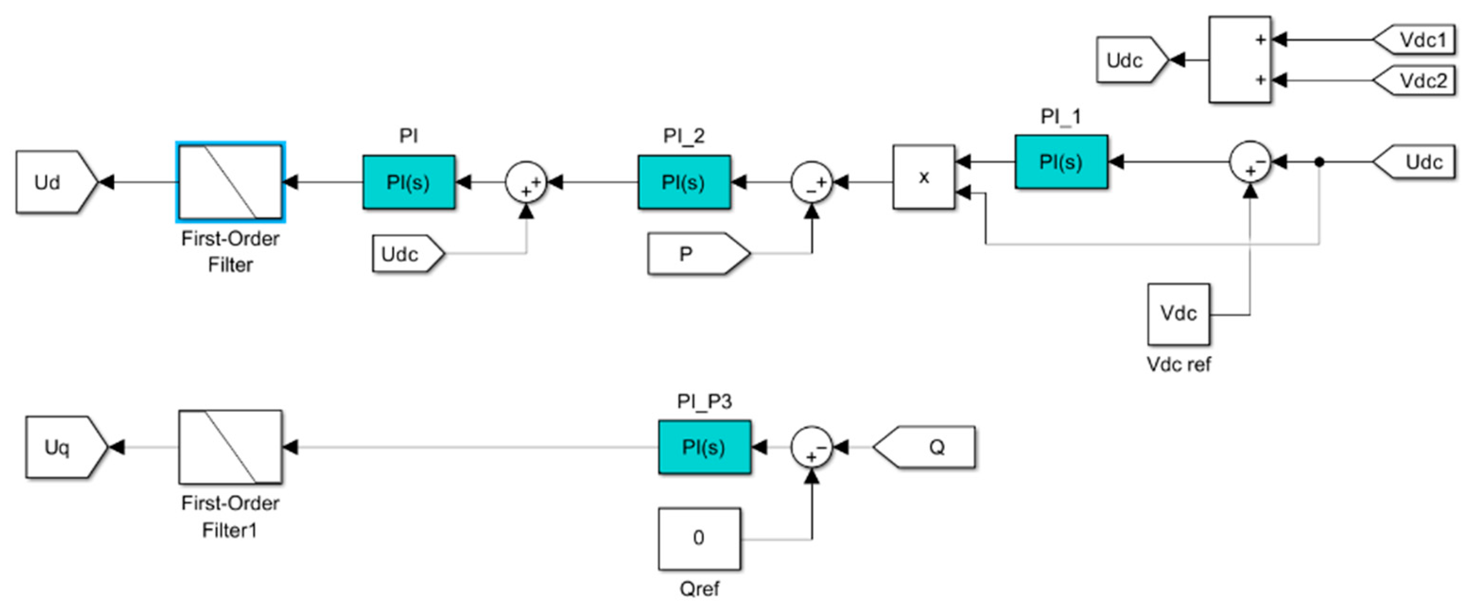
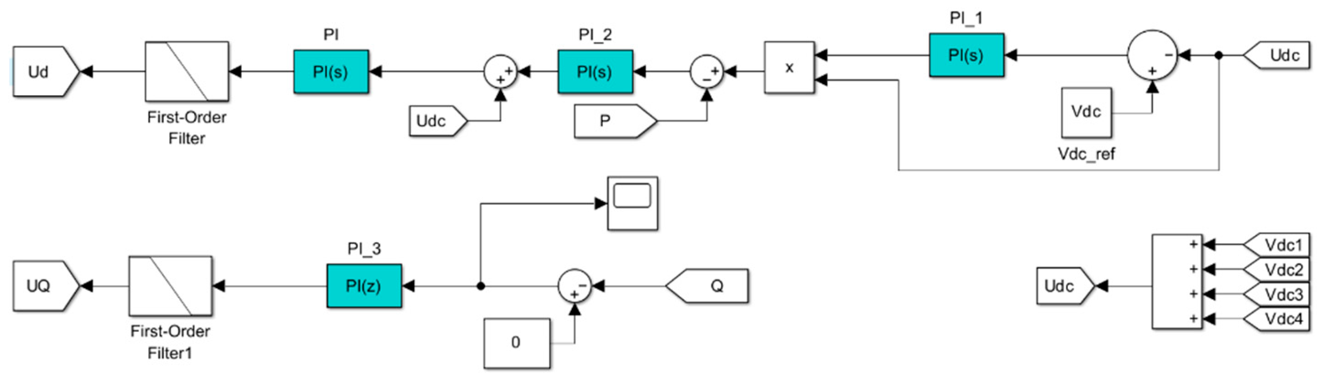
3.2. DC Voltage Control Loop

In both DPC configurations, the DC-link voltage control loop generates the active power reference P * [56,57]. The total DC-link voltage (Vdc) must be sustained at its specified reference value ( V d c _ r e f ). This is accomplished by a proportional-integral (PI) controller, formally represented as follows:
P * = K p ( V d c _ r e f V d c ) + Ki ( V d c _ r e f     V d c )   d t
The PI controller calculates P * from the Vdc reference value compared with Vdc through an Equation (1). Any voltage deviation receives fast correction from the first part, which includes K p and ( V d c _ r e f Vdc). Long-term accuracy as well as system stability emerge from the second term (Ki ∫ ( V d c _ r e f Vdc) dt) which eliminates steady-state errors. The diode-clamped multilevel inverter employs excess voltage vectors to equilibrate the neutral-point voltage by diminishing the voltage differential between capacitors (ΔV = VC1 − VC2). The insulator current directs the evolution of the capacitor voltages [58,59] when defined through the following rules:
d V C 1 d t = i n p C
d V C 2 d t = i n p C
The capacitor voltage balance in diode-clamped inverters responds to the neutral-point current ( i n p ) through Equations (2) and (3). The voltage across Vc1 rises while Vc2 falls when a positive ( i n p ) is present. When the value of ( i n p ) is negative, it applies to the opposite effect. The control method contains an adjustable small parameter (ϵ) that determines the correct switching points. When the voltage difference ΔV reaches above ϵ between VC1 and VC2, the switching states are chosen to decrease VC1. A decrease in the difference value to -ϵ triggers the selection of switching states to boost VC1.

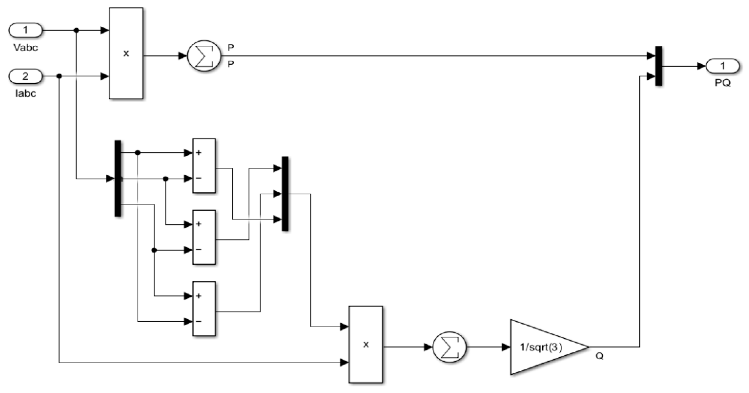
3.3. Power Calculations

The control system of Figure 2 and Figure 5 obtains three-phase voltage and current data which it uses to process active and reactive power measurements through mathematical operations that include addition and multiplication [60], where the following applies:
P = V a i a + V b i b + V c i c
Q = 1 / 3 ( V b c i a + V c a i b + V a b i c )
The P-Q theory underpins Equations (4) and (5), which calculate three-phase instantaneous active and reactive power, as illustrated in Figure 8. The real power consumption of the load is denoted by P while Q signifies reactive power moments between inductive and capacitive elements.

3.4. Direct Power Controller Block for Three-Level Inverter (DPC)

Figure 9 depicts a control system comprising three (PI) controllers: PI_2 for active power regulation, PI_3 for reactive power regulation, and PI_1 for DC-link voltage regulation. These controllers maintain precisely controlled DC-bus voltage and precisely follow power references. The PI controller in this diagram helps maintain the desired output by reducing steady-state errors and improving the stability of the system. The control system verifies active and reactive power measurements through V a b c and I a b c to begin its operation before performing a comparison with P _ r e f and Q _ r e f to adjust the operation of the PI controllers. Within its inner loop, the control circuit maintains Q _ r e f regulation using PI_3 and controls active power through PI_2 and stabilizes DC-link voltage through PI_1 which uses U d c measurements. The combination of Vdc1 and Vdc2 enables a voltage-balancing approach to realize equal distribution of the three-level Neutral-Point-Clamped inverter components, leading to capacitor unbalance prevention. The control signals generated by these processes enter the modulation phase, where either hysteresis control or pulse width modulation selects the power conversion and reliable grid support switching states. These advances enable improved STATCOM functionalities while improving the electrical grid stability during changing customer demands as well as renewable energy integration. Research enhancements in control strategies and hardware design will produce reliable power management solutions by improving efficiency.

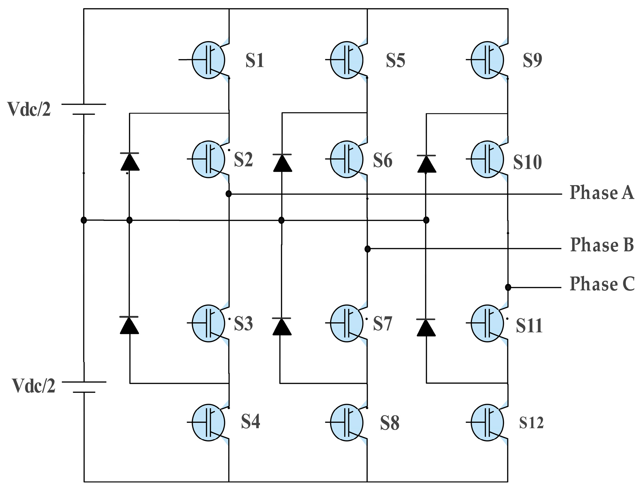
3.5. Direct Power Controller Block for Five-Level Inverter

In Figure 10, the operational principle is analogous to that of the three-level direct power controller block, with the exception of capacitor voltage measurement, which is conducted at both terminals of each of the four capacitors. The comparator then assesses this voltage against the Vdc-ref, and the resultant error signal is transmitted to the controller, mirroring the configuration in the three-level controller block.

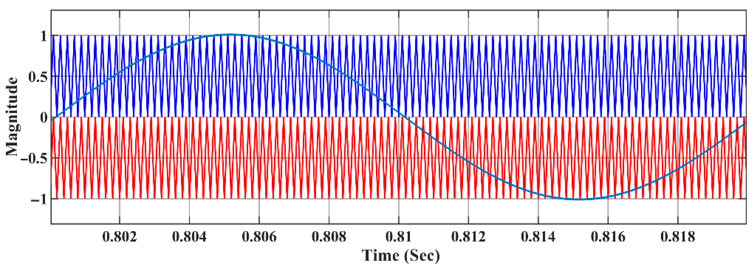
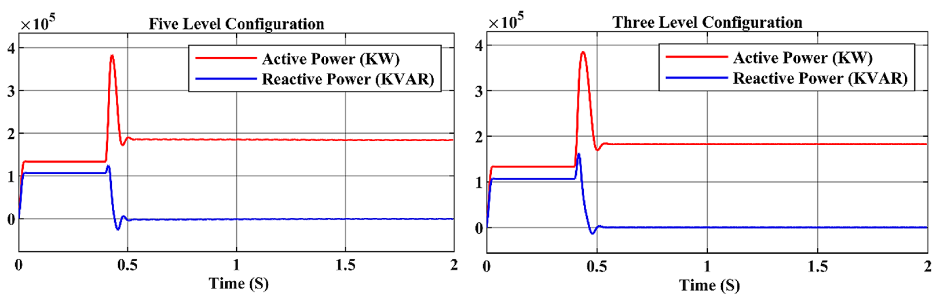
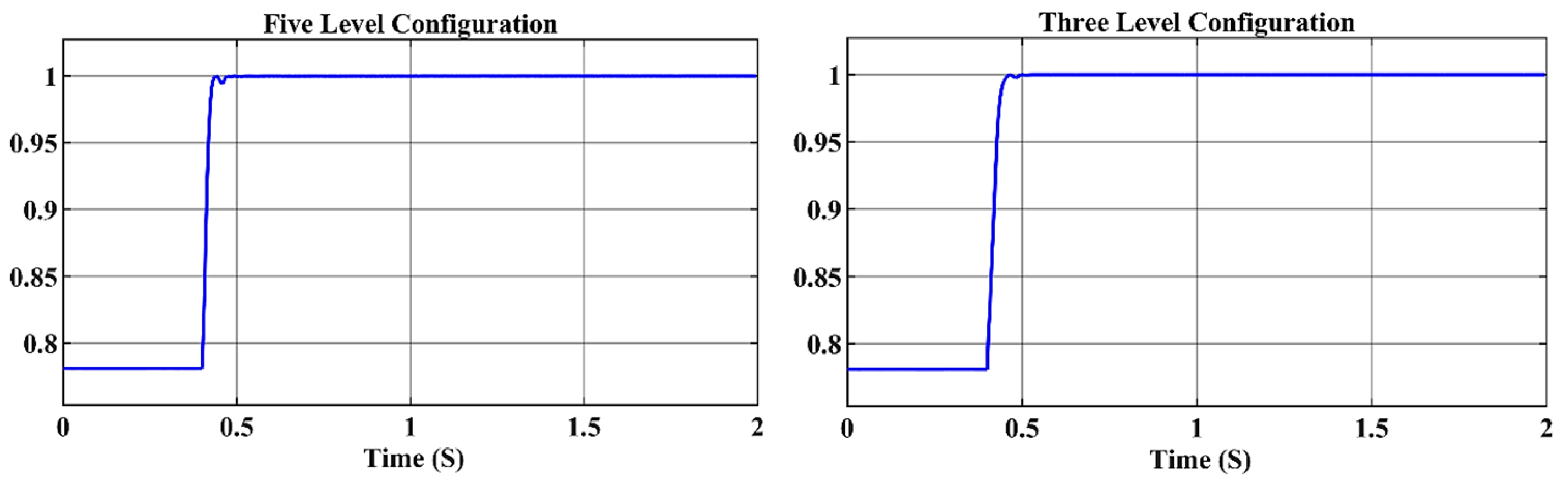
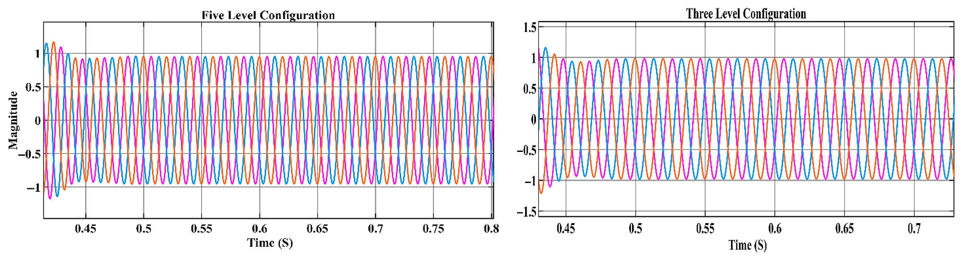
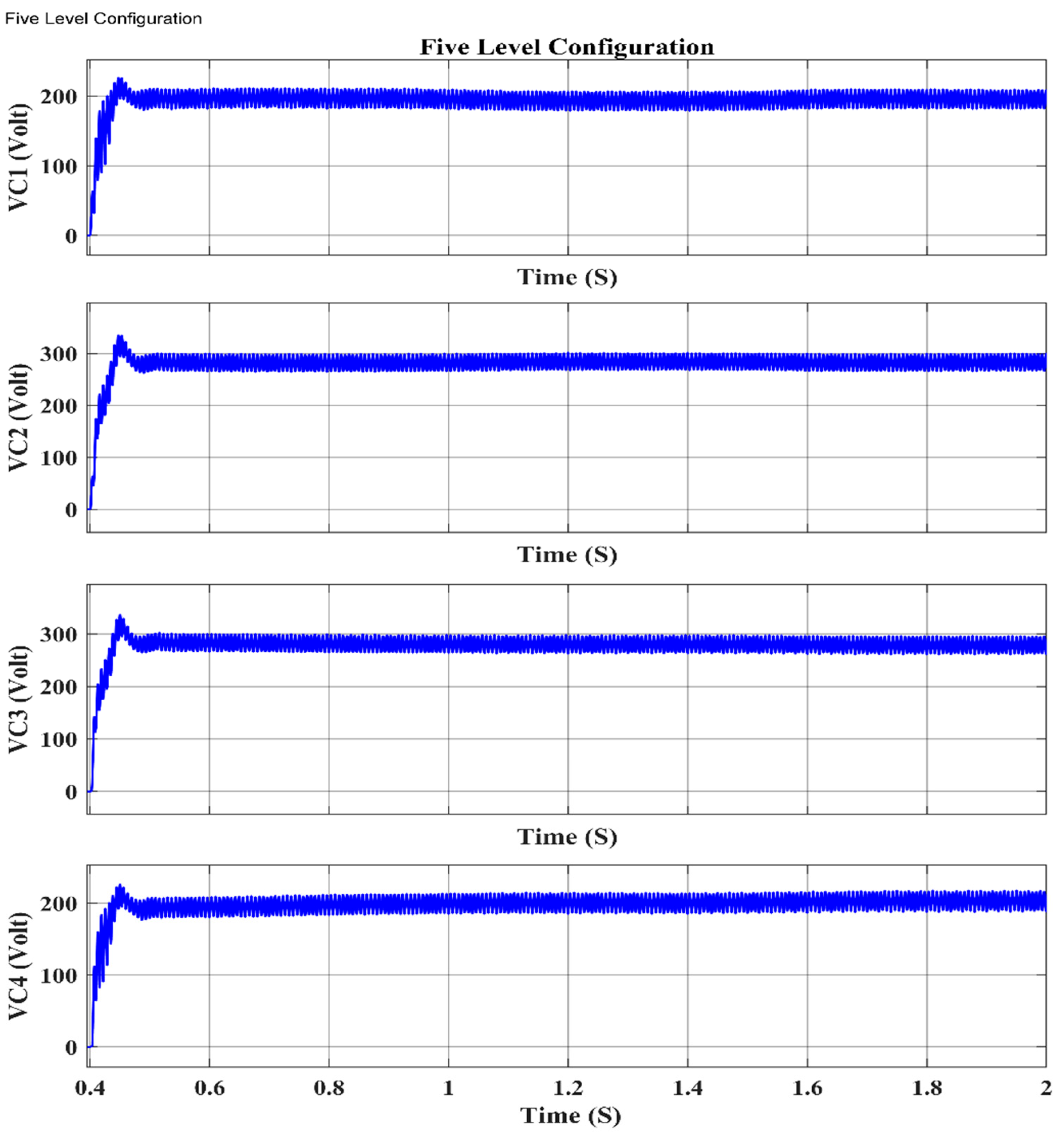
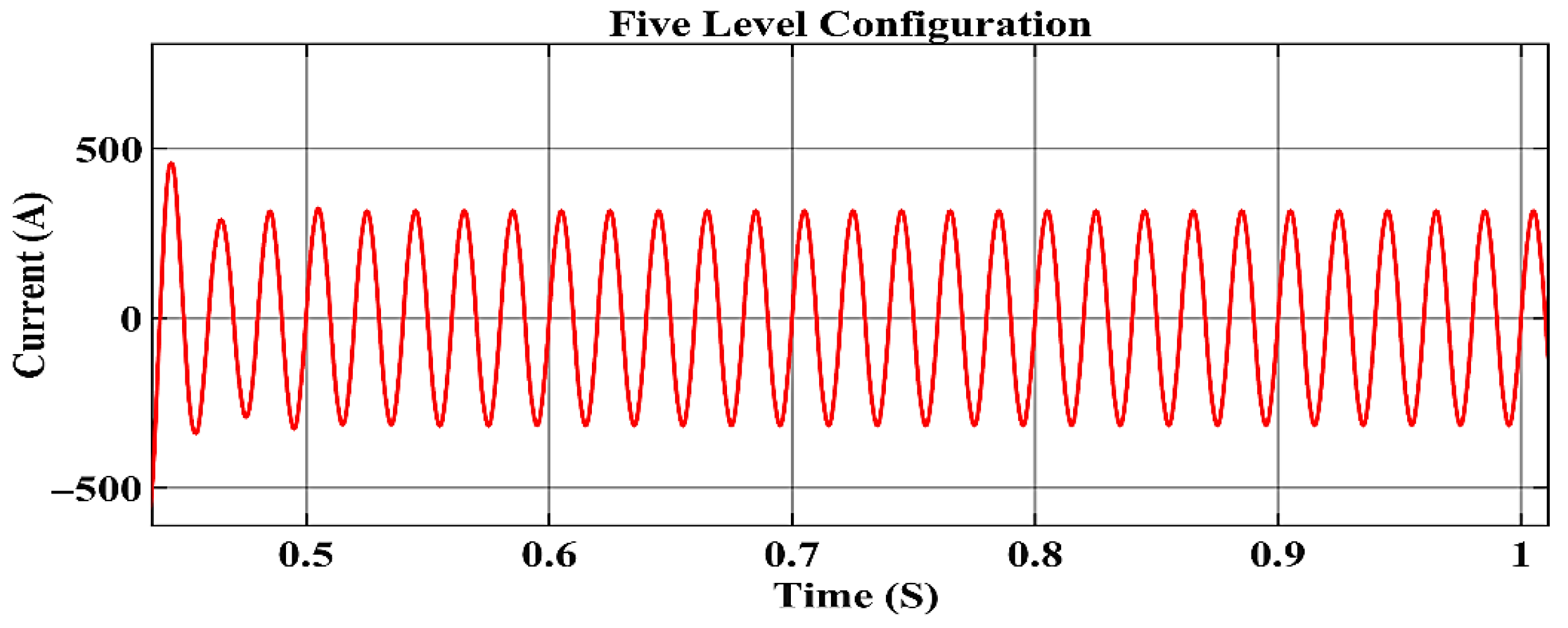
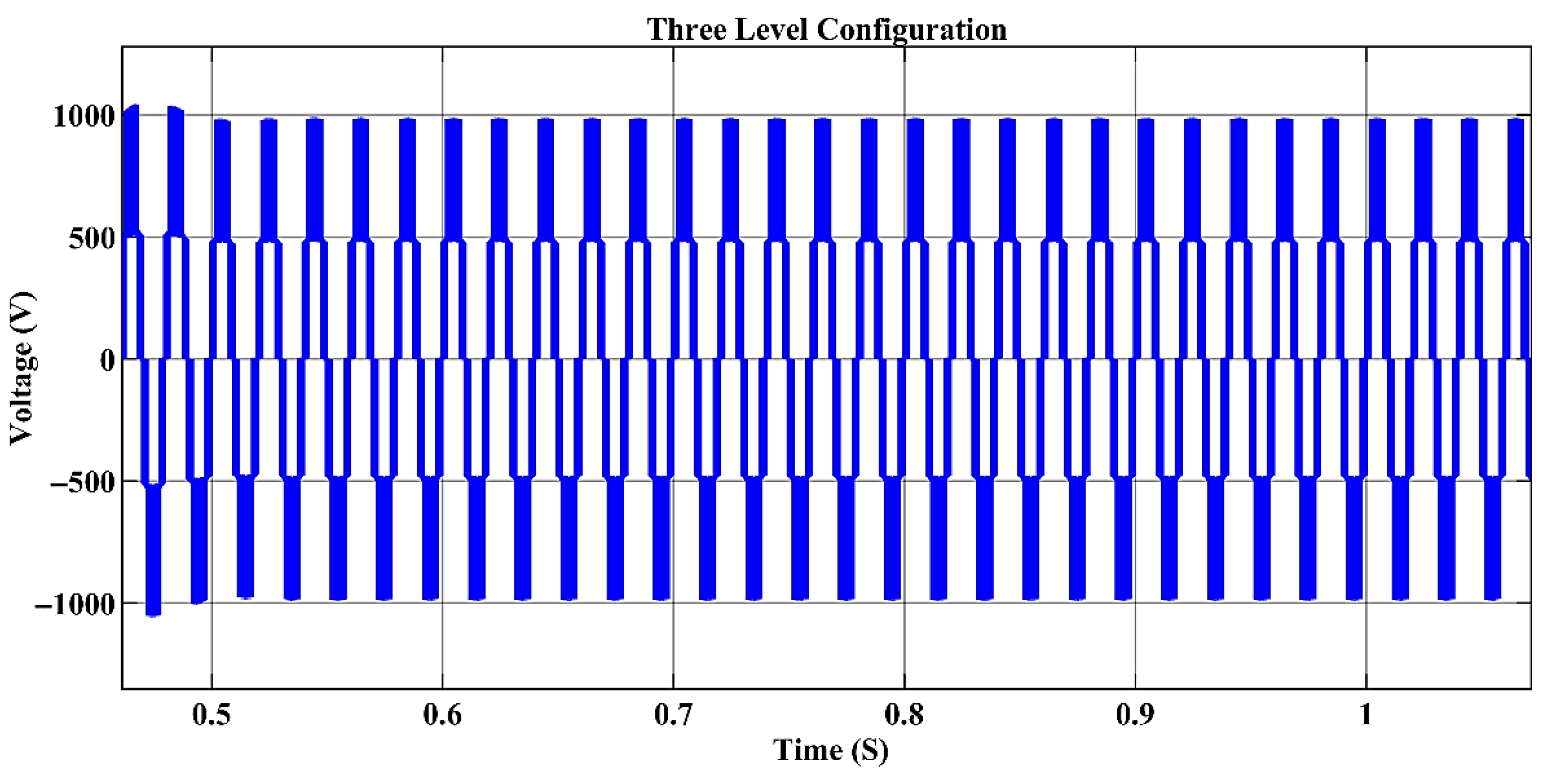
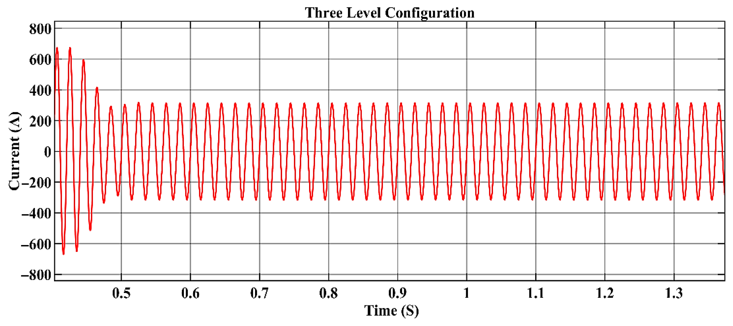
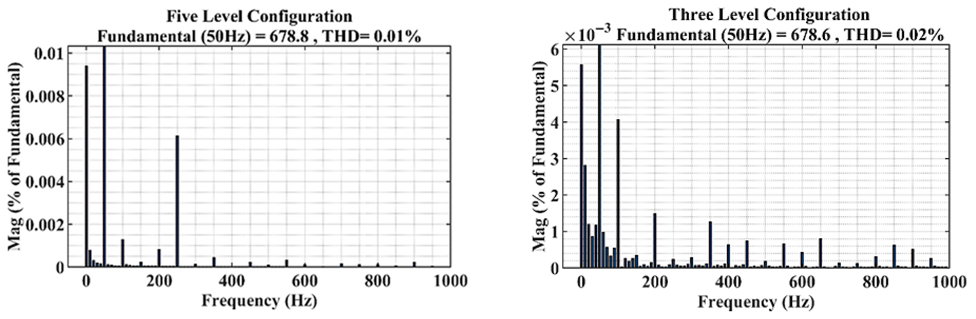
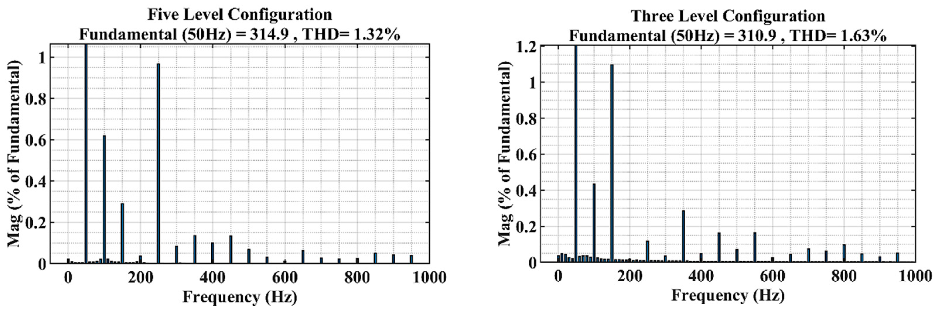
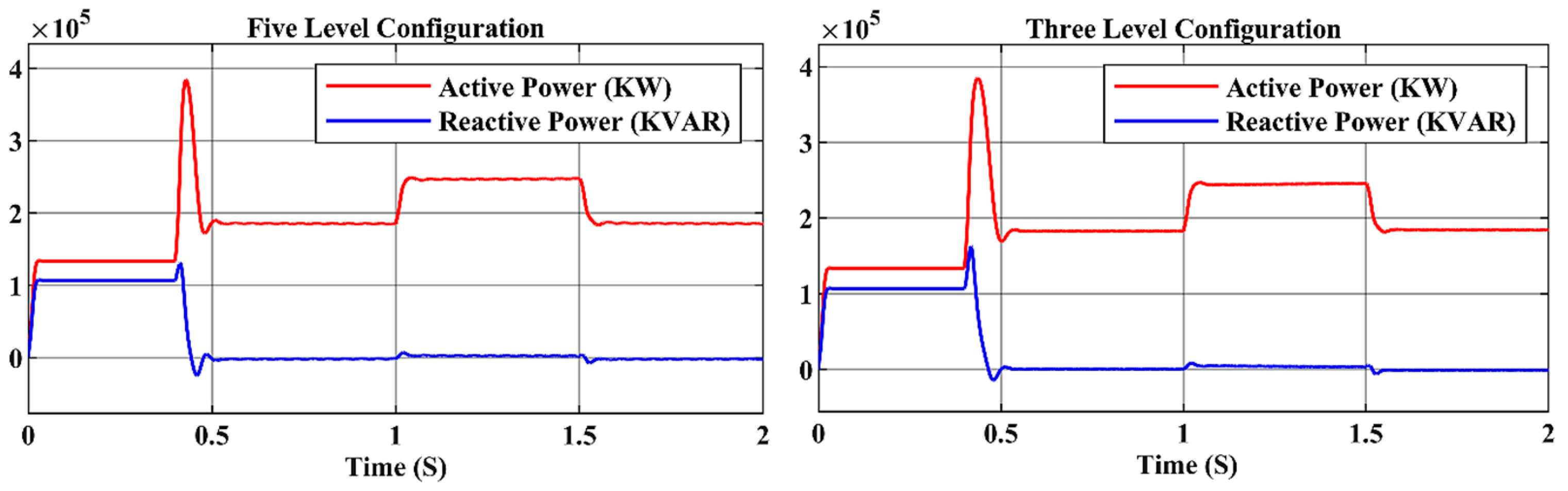
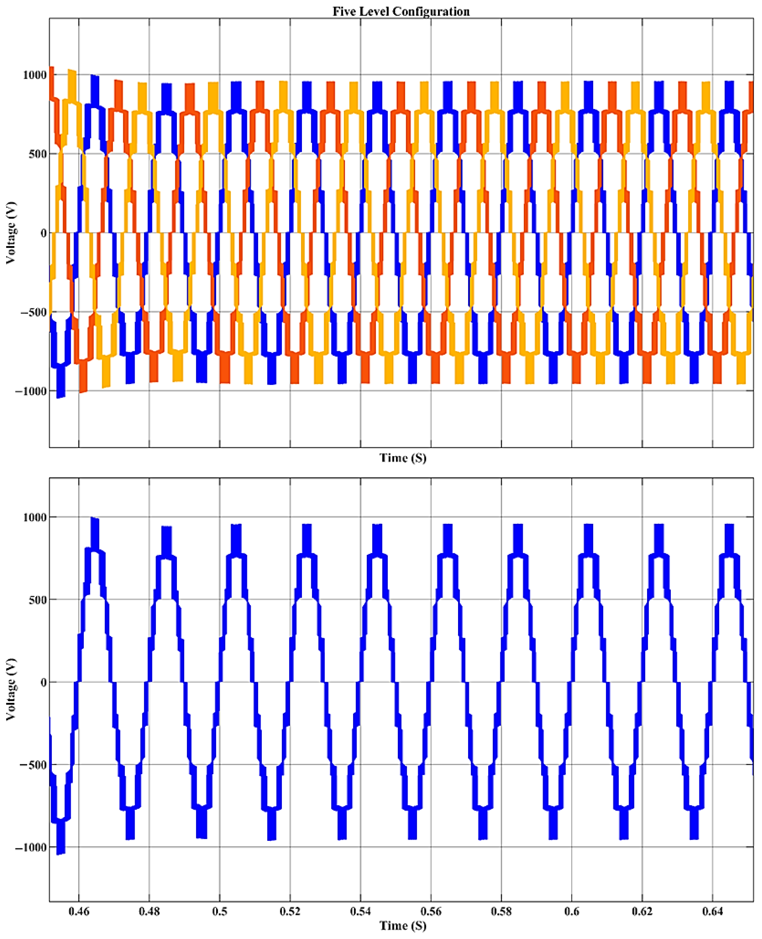
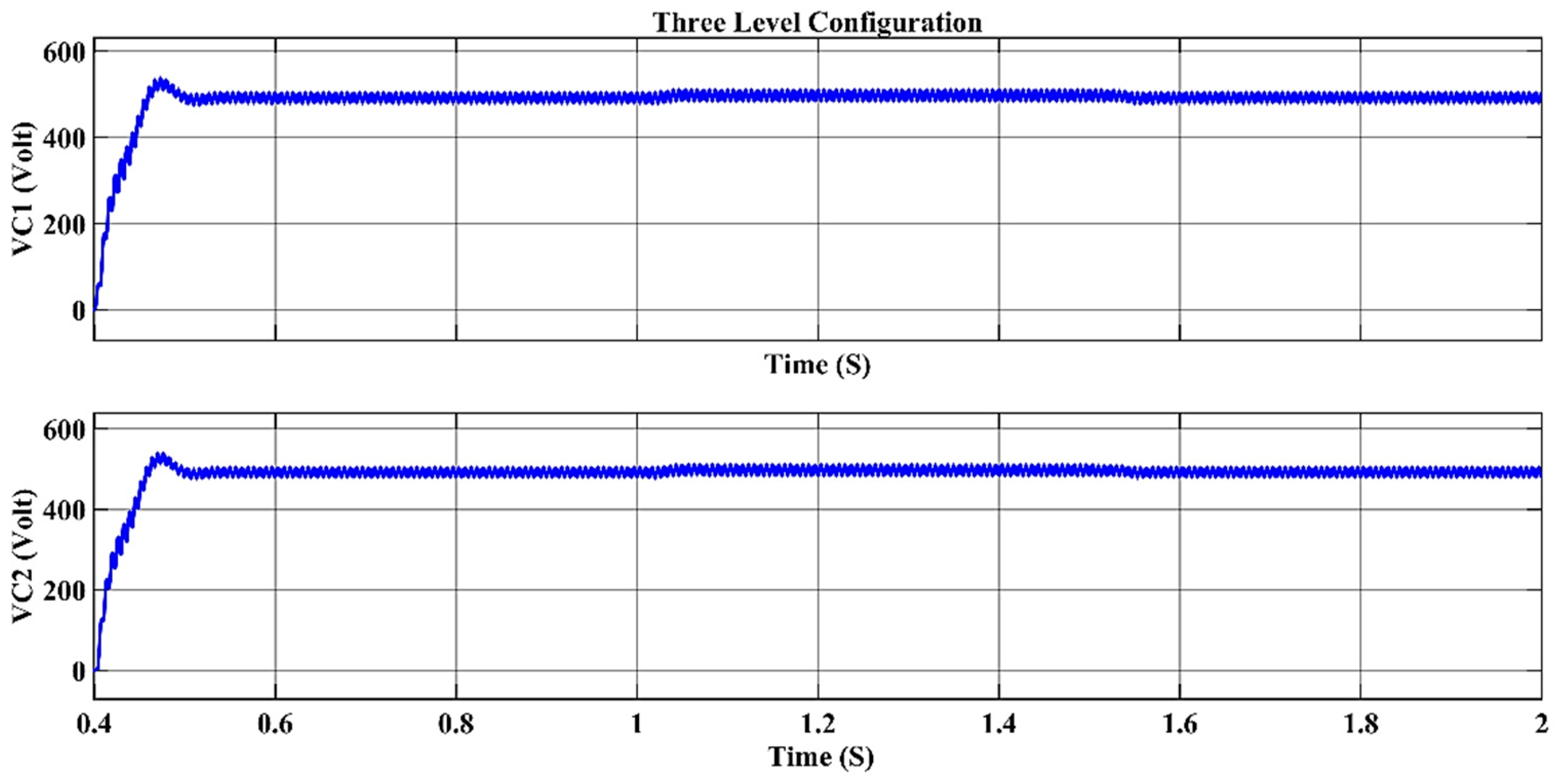
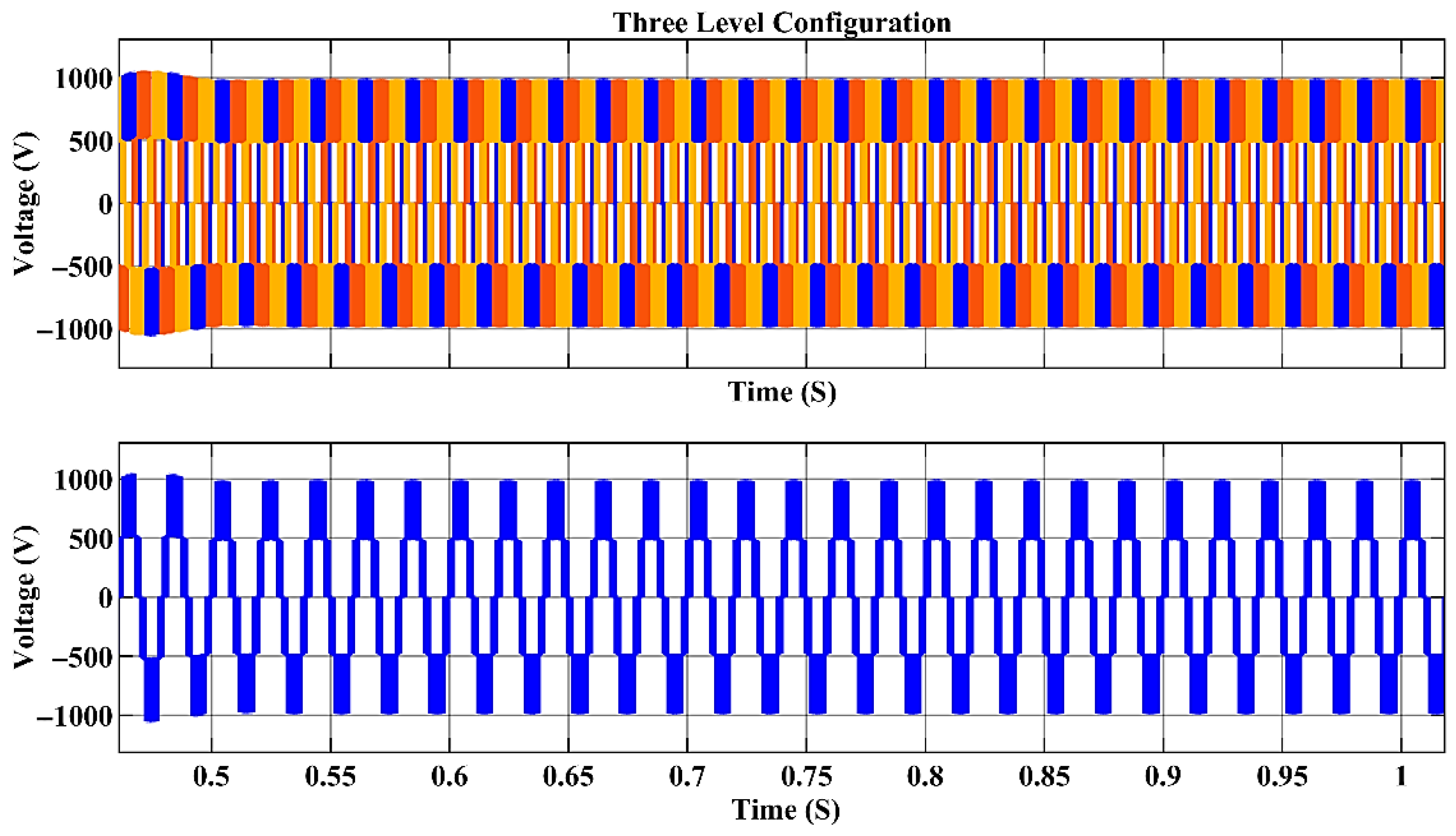
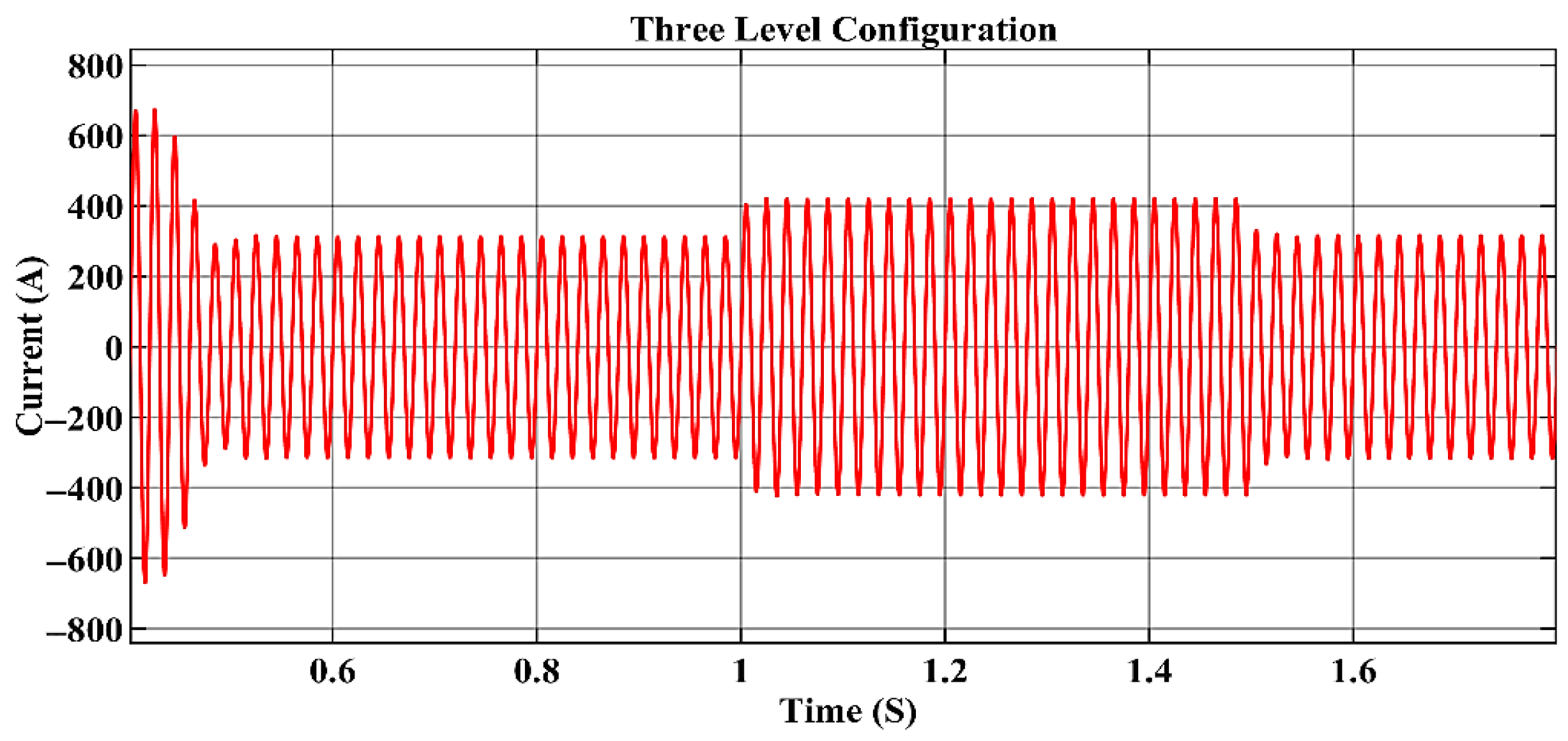
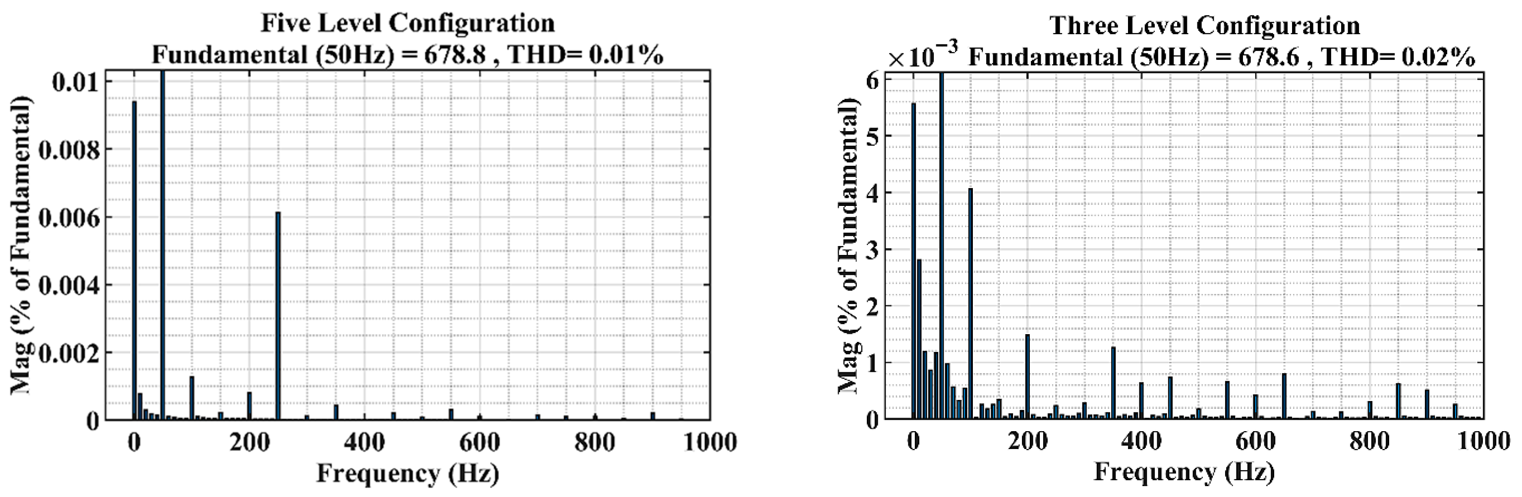
4. Results and Discussions

All simulations were carried out using MATLAB/Simulink R20233b. The simulation environment included the following toolboxes: Simscape Electrical, Simscape Power Systems, Simulink Control Design, and Signal Processing Toolbox. These were used to model power components and control systems, and to perform THD analysis.
Three PI controllers were implemented for DC-link voltage regulation (PI_1), active power (PI_2), and reactive power (PI_3) control. Their gains were selected after several tuning iterations to ensure stability and fast transient response. The selected gains are summarized in Table 3 below.
A fixed-step discrete solver [ode23t (mode. stiff/Trapezoidal)] with a 10 µs time step was used to accurately capture fast switching transients. THD levels were maintained below 5% per IEEE 519, and system responses under dynamic loads were validated through waveform analysis, power factor measurements, and voltage-balancing performance.
This careful simulation setup ensures that the results reflect realistic STATCOM operation and support the reliability of the proposed DPC-SPWM approach.
The applied step change at 0.4 s with a 100 kW and 80 kVAR load provoked a swift yet continuous modification of active and reactive power. The DPC scheme exhibits a built-in capability to respond rapidly to grid demand changes together with accurate power tracking. The simulation results of this research established that Direct Power Control (DPC) works powerfully and effectively after its implementation in STATCOM devices through three-level and five-level diode-clamped inverter configurations, as summarized in the system parameters listed in Table 4.
The power factor correction results of Figure 11 and Figure 12 prove the successful operation of both inverter setups to maintain near-unity power factors and so to improve transmission network stability. The performance can be credited to the carefully implemented PI controllers, which formed part of the DPC structure, allowing precise reactive power and DC-link voltage control. The power quality performance of the STATCOM is displayed through Figure 11, which shows source-supplied active and reactive power while Figure 12 demonstrates satisfactory power factor correction during the entire operating period.
Figure 13 illustrates the reference signals generated by the Direct Power Control (DPC) block for both inverter models. Each colored waveform in the figure represents the feedback or reference signal, with distinct colors used to enhance clarity and signal differentiation. These reference signals are essential for controlling the switching actions of the inverters and ensuring accurate power regulation.
Figure 14 validates that the DC-link capacitor voltages for both the three-level and five-level inverters function within the proper boundaries throughout load disturbances. Multilevel converters need stable DC-link capacitor voltages to guarantee operational reliability, especially when they connect to variable renewable energy systems. The output voltage waveform of the five-level inverter presented in Figure 15 demonstrates smooth transitions because it benefits from the incremental voltage steps, which reduce voltage ripple. Figure 16 showcases the source current waveform that demonstrates sinusoidal quality and low distortion during power consumption from the grid.
Figure 17 confirms stable but suboptimal DC-link voltage regulation in the three-level STATCOM (3.5% overshoot, 35 ms settling), reflecting inherent topological limitations versus the five-level converter. This aligns with its cost-simplicity trade-off, suitable for applications tolerating moderate power quality deviations.
Figure 18 illustrates the single-phase output voltage waveform of the three-level inverter, where the voltage steps are more pronounced, resulting in higher harmonic content compared to the five-level inverter. Although the source current in Figure 19 maintains a generally sinusoidal shape, its harmonic distortion increases slightly. Figure 19 illustrates the transient response of the source current for the three-level inverter. The waveform exhibits overdamped behavior with moderate settling time and minimal overshoot. This response is primarily due to conservative PI controller tuning, which was deliberately implemented to ensure system stability and prevent oscillations during grid disturbances. Although this tuning limit the speed of the transient response, it enhances current regulation reliability crucial for maintaining STATCOM performance under varying load conditions.
The assessment of THD values shows that the five-level inverter exceeds traditional solutions. The inverter output voltage together with the source current displayed improved THD measurements when running on a five-level configuration (Figure 20 and Figure 21), which maintained THD values below 5% as per the specifications in the IEEE 519 standards. The multilevel topologies achieve improved waveform quality through their elevated resolution of voltage synthesis, as demonstrated in this performance result. High-sensitivity applications need additional filtering because the three-level inverter shows more distortion in its output compared to the five-level inverter.
As for the evaluation of the response of both inverter setups under different operating environments when additional load was added, the new increased demands are displayed in Figure 22, Figure 23, Figure 24, Figure 25, Figure 26, Figure 27, Figure 28, Figure 29, Figure 30, Figure 31 and Figure 32.
The source-supplied active and reactive power becomes apparent in Figure 22 after adding the new load. The research data show that the STATCOM models using DPC methods achieved the necessary reactive power adjustments to support active power stability. There are two configurations of inverter power factors presented in Figure 23. The five-level inverter operated at a near-perfect power factor with minimal variations, demonstrating its excellent performance for reactive power compensation. The power factor of the three-level inverter reduced but stayed inside safe operational limits.
Both figures demonstrate the DC-link voltage waveform behavior for the five-level and three-level inverters in Figure 24 and Figure 27, respectively. The five-level configuration maintains balanced voltages while controlling oscillations, which demonstrates superior control over neutral-point and capacitor voltage distribution. The three-level inverter keeps voltage levels stable yet displays substantial variation because it has restricted voltage step resolution together with reduced clamping paths. The output voltage waves of the inverter are shown in Figure 25 and Figure 28. Better voltage quality emerges from the five-level inverter waveform because it shows smoother transitions. The output voltage steps from the three-level inverter result in significant waveform distortions since it creates more crude voltage transitions.
Figure 26 illustrates the source current waveform of the five-level inverter, which exhibits an almost ideal sinusoidal profile with minimal harmonic distortion. This superior performance is attributed to the increased voltage levels and enhanced harmonic attenuation inherent to the five-level diode-clamped topology.
Figure 29 shows the transient source current of the three-level inverter under additional load. The waveform has higher harmonic content due to limited voltage steps and fewer switching states. Its overdamped response with low overshoot reflects conservative PI tuning, which ensures stability but reduces responsiveness. Future work may consider adaptive tuning to improve dynamics.
The detailed harmonic analysis appears in Figure 30, Figure 31 and Figure 32. The THD measurement presented in Figure 30 validates that the five-level inverter meets IEEE 519 standards for electric power quality. The graphs of Figure 31a,b display the source current THD throughout two time spans (0.4–1 s) and (1–1.5 s) to show steady low distortion behavior in the five-level structure. The performance is strengthened through Figure 32a,b, which show enhanced harmonic behavior during dynamic load conditions.
A detailed comparison between the performance metrics of the three-level and five-level STATCOM converters is summarized in Table 5. The five-level inverter demonstrates superior harmonic performance, with lower THD and faster reactive power settling time, while the three-level inverter offers reduced computational complexity and hardware cost. This trade-off highlights the balance between power quality and implementation simplicity in selecting the appropriate topology for grid-connected applications.
In addition to performance metrics such as THD and settling time, a crucial consideration in power converter design is the hardware implementation cost and system complexity. This becomes especially relevant when comparing three-level and five-level diode-clamped inverters as in Table 6.
The five-level NPC topology requires nearly twice the number of IGBTs and gate drivers, and six times the number of clamping diodes per leg compared to the three-level topology. This translates into higher costs of materials, PCB area, and thermal management complexity.

Trade-Off Analysis: Computational Complexity vs. Performance Metrics

Although this study relies solely on simulation, the computational complexity of the control strategy remains a relevant consideration. The five-level diode-clamped inverter requires evaluating thirty-two possible switching states, compared to only eight in the three-level version. This increases the number of logical decisions and processing per time step, especially in the modulation and capacitor balancing algorithms.
Despite the higher complexity, the five-level system demonstrated superior performance, with lower THD values (1.16% vs. 1.86% for source current) and faster reactive power settling time (20 ms vs. 35 ms). These improvements come at the cost of greater control effort and processing requirements, which would be critical in real-time hardware implementation. Therefore, including computational aspects in the simulation analysis ensures practical viability and supports future experimental deployment.
These implementation trade-offs must be carefully evaluated when selecting a converter topology for real-world STATCOM applications, balancing performance gains with hardware feasibility and total system cost.

5. Conclusions

The investigation demonstrates an extensive evaluation between Direct Power Control strategies for the STATCOM system, which uses three-level and five-level diode-clamped inverter topologies. DPC demonstrates excellent performance as a power control system that maintains active and reactive power while securing voltage stability alongside enhancing power quality in electrical grids. A dynamic loading test of both inverter topologies occurred inside MATLAB/Simulink to measure harmonic effects and power correction ability and to monitor their DC voltage quality metrics. The five-level inverter shows superior performance compared to a three-level inverter across various essential operational points. The five-level inverter maintains harmonic performance because its THD operates below 5% throughout the system operation, which satisfies IEEE 519 standards [61]. The tool’s ability to generate precise voltage outputs, together with its smooth waveforms, leads to superior electrical power quality alongside diminished current distortions. The five-level inverter maintains a virtually perfect power factor under quick load transitions due to its effective reactive power compensation abilities. In contrast, the three-level inverter, while simpler and more cost-effective, shows limitations in harmonic suppression and waveform refinement. This technology remains an operational solution, especially for systems that do not need strict power quality compliance. The present power grids need advanced multilevel technological frameworks for efficiently integrating renewable energy sources together with stability functions, according to research findings. A key limitation of the current study is the assumption of an ideal, balanced grid. Future work will include testing under distorted or unbalanced voltage conditions and will explore advanced control strategies such as fuzzy DPC and NN-DPC to improve robustness and harmonic performance in more realistic operating environments. A limitation of the present study is the lack of efficiency and loss analysis. While the focus was on power quality and control performance, future work will include modeling of switching and conduction losses in semiconductors, filter losses, and capacitor balancing energy, to provide a complete evaluation of system efficiency under various loading scenarios. Another limitation of this study is the assumption of a purely sinusoidal, balanced grid. Future work will investigate the effect of grid non-idealities such as harmonics and voltage imbalance on the performance of DPC-SPWM control in multilevel STATCOM systems. The advancement of DPC-based STATCOM systems requires future research to progress in hardware development and to conduct real-time operational testing followed by hybrid modulation protocol development to boost system operational effectiveness. The ongoing power system developments constitute an essential solution for power grid requirements and ensure the reliable distribution of high-quality energy supplies. This study is primarily based on simulation; however, several measures were implemented to enhance the realism and reliability of the results. Simulation parameters were carefully selected to reflect real-world system values, and key performance indicators—including total harmonic distortion (THD), power factor, and transient response—were validated in accordance with IEEE 519 standards. The utilization of MATLAB/Simulink coupled with physics-based models (Simscape Electrical) ensures an accurate representation of system dynamics. Furthermore, the controller architecture was deliberately designed with a hardware-oriented approach to facilitate practical implementation. Collectively, these factors render the simulation outcomes not only theoretically sound but also practically relevant, providing a solid basis for subsequent experimental studies. Although this study is based solely on simulation, future work will focus on experimental validation through implementation on DSP- and FPGA-based platforms, supported by hardware-in-the-loop (HIL) testing. This will allow comprehensive assessment of practical non-idealities such as switching nonlinearities, dead-time effects, and digital control constraints. In addition, the proposed STATCOM system will be extended to support integration with renewable energy sources such as photovoltaic power and wind generation, particularly within microgrids operating in both grid-tied and islanded modes. These future directions aim to ensure robustness, scalability, and real-time feasibility under diverse and dynamic operating conditions. To address this, future work will extend simulations to include PV arrays with battery storage under various scenarios. These additions aim to evaluate the stability, voltage support, and power-sharing capabilities of the proposed DPC-SPWM STATCOM systems within smart microgrid environments.

Author Contributions

Conceptualization, D.M.M., R.F.H. and N.M.Y.; Methodology, D.M.M., R.F.H. and N.M.Y.; Software, D.M.M., R.F.H. and N.M.Y.; Validation, D.M.M., R.F.H. and N.M.Y.; Formal analysis, D.M.M., R.F.H. and N.M.Y.; Investigation, R.F.H. and N.M.Y.; Resources, R.F.H. and N.M.Y.; Data curation, R.F.H., M.A. and M.A.I.; Writing—original draft, M.A. and M.A.I.; Writing—review & editing, M.A. and M.A.I.; Project administration, M.A.; Funding acquisition, M.A. All authors have read and agreed to the published version of the manuscript.

Funding

This research was funded by the Deanship of Scientific Research at Northern Border University, Arar, KSA (through the project number NBU-FFR-2025-2124-04).

Data Availability Statement

Data are contained within the article.

Acknowledgments

The authors extend their appreciation to the Deanship of Scientific Research at Northern Border University, Arar, KSA, for funding this research (through the project number NBU-FFR-2025-2124-04).

Conflicts of Interest

The authors declare no conflicts of interest.

Abbreviations

The following abbreviations are used in this manuscript:
MDPIMultidisciplinary Digital Publishing Institute
DOAJDirectory of open access journals
TLAThree-letter acronym
LDLinear dichroism

References

  1. Blaabjerg, F.; Teodorescu, R.; Liserre, M.; Timbus, A.V. Overview of control and grid synchronization for distributed power generation systems. IEEE Trans. Ind. Electron. 2006, 53, 1398–1409. [Google Scholar] [CrossRef]
  2. Karthik, T.; Prathyusha, M.; Thirumalaivasan, R.; Janaki, M. Power quality improvement using DSTATCOM. In Proceedings of the 2019 Innovations in Power and Advanced Computing Technologies (i-PACT), Vellore, India, 22–23 March 2019. [Google Scholar]
  3. Akagi, H.; Watanabe, E.H.; Aredes, M. Instantaneous Power Theory and Applications to Power Conditioning; John Wiley & Sons: Hoboken, NJ, USA, 2017. [Google Scholar]
  4. Muñoz, J.A.; Espinoza, J.R.; Baier, C.R.; Morán, L.A.; Espinosa, E.E.; Melin, P.E.; Sbarbaro, D.G. Design of a discrete-time linear control strategy for a multicell UPQC. IEEE Trans. Ind. Electron. 2011, 59, 3797–3807. [Google Scholar] [CrossRef]
  5. Singh, B.; Al-Haddad, K.; Chandra, A. A review of active filters for power quality improvement. IEEE Trans. Ind. Electron. 1999, 46, 960–971. [Google Scholar] [CrossRef]
  6. Bozorgi, A.M.; Gholami-Khesht, H.; Farasat, M.; Mehraeen, S.; Monfared, M. Model predictive direct power control of three-phase grid-connected converters with fuzzy-based duty cycle modulation. IEEE Trans. Ind. Appl. 2018, 54, 4875–4885. [Google Scholar] [CrossRef]
  7. Kouro, S.; Malinowski, M.; Gopakumar, K.; Pou, J.; Franquelo, L.G.; Wu, B.; Rodriguez, J.; Pérez, M.A.; Leon, J.I. Recent advances and industrial applications of multilevel converters. IEEE Trans. Ind. Electron. 2010, 57, 2553–2580. [Google Scholar] [CrossRef]
  8. Nabae, A.; Takahashi, I.; Akagi, H. A new neutral-point-clamped PWM inverter. IEEE Trans. Ind. Appl. 1981, IA-17, 518–523. [Google Scholar] [CrossRef]
  9. Malinowski, M.; Gopakumar, K.; Rodriguez, J.; Perez, M.A. A survey on cascaded multilevel inverters. IEEE Trans. Ind. Electron. 2009, 57, 2197–2206. [Google Scholar] [CrossRef]
  10. Liu, J.; Zhou, L.; Yu, X.; Li, B.; Zheng, C. Design and analysis of an LCL circuit-based three-phase grid-connected inverter. IET Power Electron. 2017, 10, 232–239. [Google Scholar] [CrossRef]
  11. Bonaldo, J.P.; de Arimatéia Olímpio Filho, J.; dos Santos Alonso, A.M.; Paredes, H.K.M.; Marafão, F.P. Modeling and control of a single-phase grid-connected inverter with lcl filter. IEEE Lat. Am. Trans. 2021, 19, 250–259. [Google Scholar] [CrossRef]
  12. Busquets-Monge, S.; Rocabert, J.; Rodriguez, P.; Alepuz, S.; Bordonau, J. Multilevel diode-clamped converter for photovoltaic generators with independent voltage control of each solar array. IEEE Trans. Ind. Electron. 2008, 55, 2713–2723. [Google Scholar] [CrossRef]
  13. Rodriguez, J.; Lai, J.-S.; Peng, F.Z. Multilevel inverters: A survey of topologies, controls, and applications. IEEE Trans. Ind. Electron. 2002, 49, 724–738. [Google Scholar] [CrossRef]
  14. Abu-Rub, H.; Holtz, J.; Rodriguez, J.; Baoming, G. Medium-voltage multilevel converters—State of the art, challenges, and requirements in industrial applications. IEEE Trans. Ind. Electron. 2010, 57, 2581–2596. [Google Scholar] [CrossRef]
  15. Badoni, M.; Singh, A.; Singh, B. Power quality improvement using DSTATCOM with affine projection algorithm. IET Gener. Transm. Distrib. 2018, 12, 3261–3269. [Google Scholar] [CrossRef]
  16. Chen, J.-H.; Tan, K.-H.; Lee, Y.-D. Intelligent controlled DSTATCOM for power quality enhancement. Energies 2022, 15, 4017. [Google Scholar] [CrossRef]
  17. Khariy, A.H.; Ajel, A.R.; Gharghan, S.K.; Noaman Mohammad, N. Grid-Connected PV System for 324 kW with Improved Maximum PowerPoint Tracking. J. Tech. 2023, 5, 20–31. [Google Scholar] [CrossRef]
  18. Balogun, A.; Agoro, S.; Sunday, A.; Olajube, A.; Okafor, F. An Efficiency Optimized Direct Model Predictive Control of Induction Machine Drive. J. Tech. 2024, 6, 76–84. [Google Scholar] [CrossRef]
  19. Peng, F.Z.; Lai, J.-S. Generalized instantaneous reactive power theory for three-phase power systems. IEEE Trans. Instrum. Meas. 1996, 45, 293–297. [Google Scholar] [CrossRef]
  20. Zhang, Y.; Zhang, W.; Gao, F.; Gao, S.; Rogers, D.J. A switched-capacitor interleaved bidirectional converter with wide voltage-gain range for super capacitors in EVs. IEEE Trans. Power Electron. 2019, 35, 1536–1547. [Google Scholar] [CrossRef]
  21. Maurya, V.K.; Pandey, J.; Gaur, C.; Singh, S. Original Research Article Design analysis of intelligent controller to minimize harmonic distortion and power loss of wind energy conversion system (grid connected). J. Auton. Intell. 2024, 7. [Google Scholar] [CrossRef]
  22. Ahmad, S.; Mekhilef, S.; Mokhlis, H.; Karimi, M.; Pourdaryaei, A.; Ahmed, T.; Jhuma, U.K.; Afzal, S. Fuzzy logic-based direct power control method for pv inverter of grid-tied ac microgrid without phase-locked loop. Electronics 2021, 10, 3095. [Google Scholar] [CrossRef]
  23. Benbouhenni, H.; Bizon, N.; Mosaad, M.I.; Colak, I.; Djilali, A.B.; Gasmi, H. Enhancement of the power quality of DFIG-based dual-rotor wind turbine systems using fractional order fuzzy controller. Expert Syst. Appl. 2024, 238, 121695. [Google Scholar] [CrossRef]
  24. Chavali, R.V.; Dey, A.; Das, B. An abc Reference Frame Hysteresis Current Controller for Grid Connected Converter With Constant Switching Frequency Operation. IEEE Trans. Ind. Electron. 2024, 72, 1159–1169. [Google Scholar] [CrossRef]
  25. Blaabjerg, F.; Iov, F.; Kerekes, T.; Teodorescu, R.; Ma, K. Power electronics-key technology for renewable energy systems. In Proceedings of the 2011 2nd Power Electronics, Drive Systems and Technologies Conference, Tehran, Iran, 16–17 February 2011; pp. 445–466. [Google Scholar]
  26. Mirdas, Q.H.; Yasin, N.M.; Alshamaa, N.K. Grey wolf optimization-based improved closed-loop speed control for a 3-phase IM motor drive with SVPWM switching and V/f control. In Proceedings of the 2022 International Conference on Engineering & MIS (ICEMIS), Istanbul, Turkey, 4–6 July 2022; pp. 1–6. [Google Scholar]
  27. Rodríguez, J.; Bernet, S.; Wu, B.; Pontt, J.O.; Kouro, S. Multilevel voltage-source-converter topologies for industrial medium-voltage drives. IEEE Trans. Ind. Electron. 2007, 54, 2930–2945. [Google Scholar] [CrossRef]
  28. Perez, M.A.; Cortés, P.; Rodríguez, J. Predictive control algorithm technique for multilevel asymmetric cascaded H-bridge inverters. IEEE Trans. Ind. Electron. 2008, 55, 4354–4361. [Google Scholar] [CrossRef]
  29. Kouro, S.; Perez, M.A.; Rodriguez, J.; Llor, A.M.; Young, H.A. Model predictive control: MPC’s role in the evolution of power electronics. IEEE Ind. Electron. Mag. 2015, 9, 8–21. [Google Scholar] [CrossRef]
  30. Newman, M.J.; Holmes, D.G. Delta operator digital filters for high performance inverter applications. IEEE Trans. Power Electron. 2003, 18, 447–454. [Google Scholar] [CrossRef]
  31. Vazquez, S.; Rodriguez, J.; Rivera, M.; Franquelo, L.G.; Norambuena, M. Model predictive control for power converters and drives: Advances and trends. IEEE Trans. Ind. Electron. 2016, 64, 935–947. [Google Scholar] [CrossRef]
  32. Yasin, N.M. Simulation of Solar Cell and sinusoidal pulse width modulation inverter Using MATLAB and Proteus. In Proceedings of the 2019 4th Scientific International Conference Najaf (SICN), Najef, Iraq, 29–30 April 2019; pp. 86–91. [Google Scholar]
  33. Ghafour, Z.A.; Ajel, A.R.; Yasin, N.M. Super lift Luo converter using MPPT strategy for PV system. In Proceedings of the AIP Conference Proceedings, Baghdad, Iraq, 15–16 June 2022. [Google Scholar]
  34. Dardabi, C.; Álvarez, S.C.; Djebli, A. An Artificial-Neural-Network-Based Direct Power Control Approach for Doubly Fed Induction Generators in Wind Power Systems. Energies 2025, 18, 1989. [Google Scholar] [CrossRef]
  35. Sheh Zad, H.; Ulasyar, A.; Zohaib, A.; Khattak, A. Adaptive sliding mode predictive power control of three-phase AC/DC converters. Proc. Inst. Mech. Eng. Part I J. Syst. Control. Eng. 2022, 236, 897–912. [Google Scholar] [CrossRef]
  36. Benbouhenni, H.; Zellouma, D.; Bizon, N.; Colak, I. A new PI (1+ PI) controller to mitigate power ripples of a variable-speed dual-rotor wind power system using direct power control. Energy Rep. 2023, 10, 3580–3598. [Google Scholar] [CrossRef]
  37. Benbouhenni, H.; Bizon, N. A new direct power control method of the DFIG-DRWT system using neural PI controllers and four-level neural modified SVM technique. J. Appl. Res. Technol. 2023, 21, 36–55. [Google Scholar] [CrossRef]
  38. Ahmad, S.; Jhuma, U.K.; Karimi, M.; Pourdaryaei, A.; Mekhilef, S.; Mokhlis, H.; Kauhaniemi, K. Direct power control based on point of common coupling voltage modulation for grid-tied AC microgrid PV inverter. IEEE Access 2022, 10, 109187–109202. [Google Scholar] [CrossRef]
  39. Alturki, Y.A.; Alhussainy, A.A.; Alghamdi, S.M.; Rawa, M. A Novel Point of Common Coupling Direct Power Control Method for Grid Integration of Renewable Energy Sources: Performance Evaluation among Power Quality Phenomena. Energies 2024, 17, 5111. [Google Scholar] [CrossRef]
  40. Yang, X.; Zhang, Z.; Xu, M.; Li, S.; Zhang, Y.; Zhu, X.-F.; Ouyang, X.; Alù, A. Digital non-Foster-inspired electronics for broadband impedance matching. Nat. Commun. 2024, 15, 4346. [Google Scholar] [CrossRef]
  41. Zhang, Y.; Yang, X.; Zhang, Z. High-Efficiency Broadband Electroacoustic Energy Conversion Using Non-Foster-Inspired Circuit and Adaptively Switched Capacitor. IEEE Trans. Ind. Electron. 2025. early access. [Google Scholar] [CrossRef]
  42. Zhang, Y.; Jiao, J.; Liu, J. Direct power control of PWM rectifiers with online inductance identification under unbalanced and distorted network conditions. IEEE Trans. Power Electron. 2019, 34, 12524–12537. [Google Scholar] [CrossRef]
  43. Singh, B.; Murthy, S.S.; Gupta, S. STATCOM-based voltage regulator for self-excited induction generator feeding nonlinear loads. IEEE Trans. Ind. Electron. 2006, 53, 1437–1452. [Google Scholar] [CrossRef]
  44. Kouro, S.; Cortés, P.; Vargas, R.; Ammann, U.; Rodríguez, J. Model predictive control—A simple and powerful method to control power converters. IEEE Trans. Ind. Electron. 2008, 56, 1826–1838. [Google Scholar] [CrossRef]
  45. Sguarezi, A. Model Predictive Control for Doubly-Fed Induction Generators and Three-Phase Power Converters; Elsevier: Amsterdam, The Netherlands, 2022. [Google Scholar]
  46. Tawfiq, K.B.; Sergeant, P.; Mansour, A.S. Comparative Analysis of Space Vector Pulse-Width Modulation Techniques of Three-Phase Inverter to Minimize Common Mode Voltage and/or Switching Losses. Mathematics 2024, 12, 2832. [Google Scholar] [CrossRef]
  47. Shyaa, S.S.; Hassan, R.F. Design and Software Implementation of Multilevel Diode Clamped Converter. In Proceedings of the IOP Conference Series: Materials Science and Engineering, Baghdad, Iraq, 15 April 2020; p. 012140. [Google Scholar]
  48. Dan, H.; Peng, T.; Su, M.; Sun, Y.; Zhang, G.; Xiong, W. Implementation of phase disposition modulation method for the three-level diode-clamped matrix converter. IET Power Electron. 2015, 8, 2107–2114. [Google Scholar] [CrossRef]
  49. Ben Mahmoud, Z.; Khedher, A. A Comprehensive Review on Space Vector Based-PWM Techniques for Common Mode Voltage Mitigation in Photovoltaic Multi-Level Inverters. Energies 2024, 17, 916. [Google Scholar] [CrossRef]
  50. Arora, S.; Balsara, P.T.; Bhatia, D. Digital pulsewidth modulation (DPWM) using direct digital synthesis. IEEE J. Emerg. Sel. Top. Power Electron. 2021, 10, 4231–4244. [Google Scholar] [CrossRef]
  51. Kasim, M.Q.; Hassan, R.F. Reduced computational burden model predictive current control of asymmetric stacked multi-level inverter based STATCOM. In Proceedings of the 2021 IEEE International Conference on Automatic Control & Intelligent Systems (I2CACIS), Shah Alam, Malaysia, 26 June 2021; pp. 374–379. [Google Scholar]
  52. Kasim, M.Q.; Hassan, R.F. Active voltage balancing strategy of asymmetric stacked multilevel inverter. Indones. J. Electr. Eng. Comput. Sci. 2021, 23, 665–674. [Google Scholar] [CrossRef]
  53. Busquets-Monge, S.; Alepuz, S.; Bordonau, J.; Peracaula, J. Voltage balancing control of diode-clamped multilevel converters with passive front-ends. IEEE Trans. Power Electron. 2008, 23, 1751–1758. [Google Scholar] [CrossRef]
  54. Taha, S.A.; Al-Sagar, Z.S.; Abdulsada, M.A.; Alruwaili, M.; Ibrahim, M.A. Design of an Efficient MPPT Topology Based on a Grey Wolf Optimizer-Particle Swarm Optimization (GWO-PSO) Algorithm for a Grid-Tied Solar Inverter Under Variable Rapid-Change Irradiance. Energies 2025, 18, 1997. [Google Scholar] [CrossRef]
  55. Mahato, B.; Majumdar, S.; Jana, K.C. Carrier-based PWM techniques for multi-level inverters: A comprehensive performance study. Gazi Univ. J. Sci. Part A Eng. Innov. 2018, 5, 101–111. [Google Scholar]
  56. Ramasamy, T.; Abdul Basheer, A.; Tak, M.-H.; Joo, Y.-H.; Lee, S.-R. An effective dc-link voltage control strategy for grid-connected PMVG-based wind energy conversion system. Energies 2022, 15, 2931. [Google Scholar] [CrossRef]
  57. Zhang, Y.; Wang, Z.; Jiao, J.; Liu, J. Grid-voltage sensorless model predictive control of three-phase PWM rectifier under unbalanced and distorted grid voltages. IEEE Trans. Power Electron. 2019, 35, 8663–8672. [Google Scholar] [CrossRef]
  58. Lee, S.S.; Lim, C.S.; Lee, K.-B. Novel active-neutral-point-clamped inverters with improved voltage-boosting capability. IEEE Trans. Power Electron. 2019, 35, 5978–5986. [Google Scholar] [CrossRef]
  59. Gang, L.; Dafang, W.; Miaoran, W.; Cheng, Z.; Mingyu, W. Neutral-point voltage balancing in three-level inverters using an optimized virtual space vector PWM with reduced commutations. IEEE Trans. Ind. Electron. 2018, 65, 6969. [Google Scholar]
  60. Alonso-Martı, J.; Arnaltes, S. Direct power control of grid connected PV systems with three level NPC inverter. Sol. Energy 2010, 84, 1175–1186. [Google Scholar] [CrossRef]
  61. Langella, R.; Testa, A.; Alii, E. IEEE recommended practice and requirements for harmonic control in electric power systems. In IEEE Recommended Practice; IEEE: New York, NY, USA, 2014. [Google Scholar]
Figure 1. Block diagram of conventional Direct Power Control.
Energies 18 03582 g001
Figure 2. Direct Power Control (DPC) scheme for a three-level inverter functioning as a STATCOM.
Energies 18 03582 g002
Figure 3. Three-level Neutral-Point-Clamped (NPC) voltage source inverter topology.
Energies 18 03582 g003
Figure 4. Three-level sinusoidal pulse width modulation with reference signal.
Energies 18 03582 g004
Figure 5. Direct Power Control (DPC) scheme for a five-level inverter functioning as a STATCOM.
Energies 18 03582 g005
Figure 6. Circuit diagram of a five-level Neutral-Point-Clamped inverter.
Energies 18 03582 g006
Figure 7. Carrier arrangement using Phase Disposition for a five-level diode-clamped inverter.
Energies 18 03582 g007
Figure 8. Block diagram for active and reactive power calculations.
Energies 18 03582 g008
Figure 9. Block diagram of direct power controller for DPC with three-level inverter.
Energies 18 03582 g009
Figure 10. Block diagram of direct power controller for DPC with five-level inverter.
Energies 18 03582 g010
Figure 11. Source-supplied power.
Energies 18 03582 g011
Figure 12. Power factor measurements.
Energies 18 03582 g012
Figure 13. Reference signals from the DPC block.
Energies 18 03582 g013
Figure 14. DC-link capacitor voltages of five-level inverter.
Energies 18 03582 g014
Figure 15. Single-phase inverter output voltage waveforms.
Energies 18 03582 g015
Figure 16. Source current waveform of five-level inverter.
Energies 18 03582 g016
Figure 17. DC-link capacitor voltages of three-level inverter.
Energies 18 03582 g017
Figure 18. Single phase of three-level inverter output voltage waveform.
Energies 18 03582 g018
Figure 19. Source current waveform of three-level inverter.
Energies 18 03582 g019
Figure 20. THD for inverter output voltage after the filter.
Energies 18 03582 g020
Figure 21. THD for the source current.
Energies 18 03582 g021
Figure 22. Source-supplied power after adding another lagging load.
Energies 18 03582 g022
Figure 23. Power factor measurement for both five- and three-level configurations.
Energies 18 03582 g023
Figure 24. DC-link voltages for five-level configurations after adding another lagging load.
Energies 18 03582 g024
Figure 25. DC single phase and three phases of five-level inverter output voltage waveforms.
Energies 18 03582 g025
Figure 26. Source current waveform of five-level inverter after adding Load 2.
Energies 18 03582 g026
Figure 27. DC-link voltages for three-level configurations after adding another lagging load.
Energies 18 03582 g027
Figure 28. DC single phase and three phases of three-level inverter output voltage waveforms.
Energies 18 03582 g028
Figure 29. Source current waveform of three-level inverter after adding Load 2.
Energies 18 03582 g029
Figure 30. THD for inverter output voltage after the filter when Load 2 is present.
Energies 18 03582 g030
Figure 31. (a) THD for the source current (0.4–1) s. (b) THD for the source current (1–1.5) s.
Energies 18 03582 g031
Figure 32. (a) THD for the source current (0.4–1) period. (b) THD for the source current (1–1.5) period.
Energies 18 03582 g032
Table 1. Switching states and corresponding output voltage levels.
Switching StatesPhase ATerminal Voltage
S1S2S3S4
PONONOFFOFF+Vdc/2
OOFFONONOFF0
NOFFOFFONON−Vdc/2
Table 2. Output voltage levels based on switching states (Phase A).
Switching StatesTerminal Voltage
S1S2S3S4S5S6S7S8
ONONONONOFFOFFOFFOFFVdc/2
OFFONONONONOFFOFFOFFVdc/4
OFFOFFONONONONOFFOFF0
OFFOFFOFFONONONONOFF−Vdc/4
OFFOFFOFFOFFONONONON−Vdc/2
Table 3. Parameter values of PI controllers for simulated STATCOM systems.
ControllerKpKi
PI_10.00010.00001
PI_20.00050.00001
PI_30.0060.0094
Note: The PI controller gains are defined in a per-unit (p.u) system, normalized with respect to the base values of voltage, current, and power. The relatively small gain values result from the large capacitance and inductance parameters used in the STATCOM model. For real-time hardware implementation, these gains would be appropriately scaled according to the converter’s physical parameters and sampling constraints to ensure stable and responsive control performance.
Table 4. System parameters used in STATCOM simulation.
ParameterValue
DC-link voltage1000 V
Utility line voltage480 V
Utility frequency50 Hz
Average switching frequency5 kHz
Inverter loss resistance R1 mΩ
Filter inverter side inductor2 mH
Filter inverter side resistor0.8 Ω
DC-link capacitor for three-level inverter8000 µF
DC-link capacitor for five-level inverter5000 µF
Load 1
Inductive load
0.78 lagging PF
Active Power100 kW
Reactive Power80 kVAR
Load 2
Inductive load
0.98 lagging PF
Active Power40 kW
Reactive Power8 kvar
Table 5. Comparison between three-level and five-level STATCOM converters.
Metric3-Level STATCOM5-Level STATCOM
Current THD(0.4–1) s(1–1.5) s
1.86%1.16%
Voltage THD after the filter0.02%0.01%
Reactive Power Settling Time35 ms20 ms
DC-Link Voltage Overshoot3.5%1.2%
Steady-State Power Factor0.9850.998
Computational LoadLow (8 switching states)High (32 switching states)
Table 6. Component count comparison.
5-Level NPC (Per Phase Leg)3-Level NPC (Per Phase Leg)Component
84IGBTs/Switches
122Diodes (clamping)
42DC-Link Capacitors
84Gate Driver Circuits
Disclaimer/Publisher’s Note: The statements, opinions and data contained in all publications are solely those of the individual author(s) and contributor(s) and not of MDPI and/or the editor(s). MDPI and/or the editor(s) disclaim responsibility for any injury to people or property resulting from any ideas, methods, instructions or products referred to in the content.

