1. Introduction to Cryogenic Requirements of Big Science Research Infrastructure
Big Science research infrastructures, especially high-energy accelerators, free-electron lasers, spallation sources, and thermonuclear reactors, make extensive use of superconductivity and helium cryogenics. Superconducting high-field magnets allow for both bending and focusing high-energy lepton or hadron beams, while superconducting radiofrequency cavities are state-of-the-art accelerating structures in presently exploited and constructed machines, e.g., the LHC, XFEL, ESS, or PIPII. High-field superconducting magnets are also a must in tokamaks and stellarators aimed at thermonuclear fusion with a positive energy gain. Large-scale helium cryogenic systems, which ensure adequate cooling of superconducting devices, are therefore unavoidable in the construction of most Big Science research infrastructure [
1,
2].
Despite the great hopes associated with the high-temperature superconductors discovered in 1986 [
3], the only superconductors from which reliable superconducting high-field magnets and SFR cavities can be constructed are Nb, NbTi, and Nb
3Sn. NbTi magnets are cryostated either at 4. K or 1.8 K if a magnetic field exceeding about 5 Tesla is required (LHC, TORE SUPRA [
4,
5]). Magnets made of Nb
3Sn are cryostated at 4.5 K or slightly higher, not exceeding 10 K. The cooling medium can be two-phase or supercritical helium. The thermodynamically optimal operation temperature of superconducting niobium SFR cavities is 2 K. The only cryogen allowing such a low temperature to be reached is helium in the form of superfluid helium [
6,
7,
8].
Additionally, helium can be transferred over long distances in a supercritical state, allowing for both a low-temperature and single-phase flow. In state-of-the-art Big Science cryogenic systems, helium is used in all thermodynamic states depicted in
Figure 1.
The cooling power requirements of Big Science helium cryogenic systems are of the order of several hundred kW at 4.5 K. Taking into account the thermodynamic efficiency of state-of-the-art cryoplants, which do not exceed a 40% Carnot cycle efficiency, the electrical power requirement of big helium cryogenic systems may approach 1000 MWe.
The above requirements make big helium cryogenics a very challenging system based on advanced materials and technologies, requiring sophisticated engineering and manufacturing skills. The systems must fulfil contradictory requirements: they must be robust to withstand thermomechanical loads and, in the case of superconducting magnets, high Lorentz forces and, at the same time, the design must guarantee very low heat fluxes to low-temperature regions of the systems. We present the general architecture of a cryogenic distribution system, analyze the design options of the chosen system components for the example of PolFEL cryogenics, and demonstrate the use of entropy analysis, allowing for the minimization of energy consumption by cryoplants.
2. Architecture of Helium Cryogenic Systems
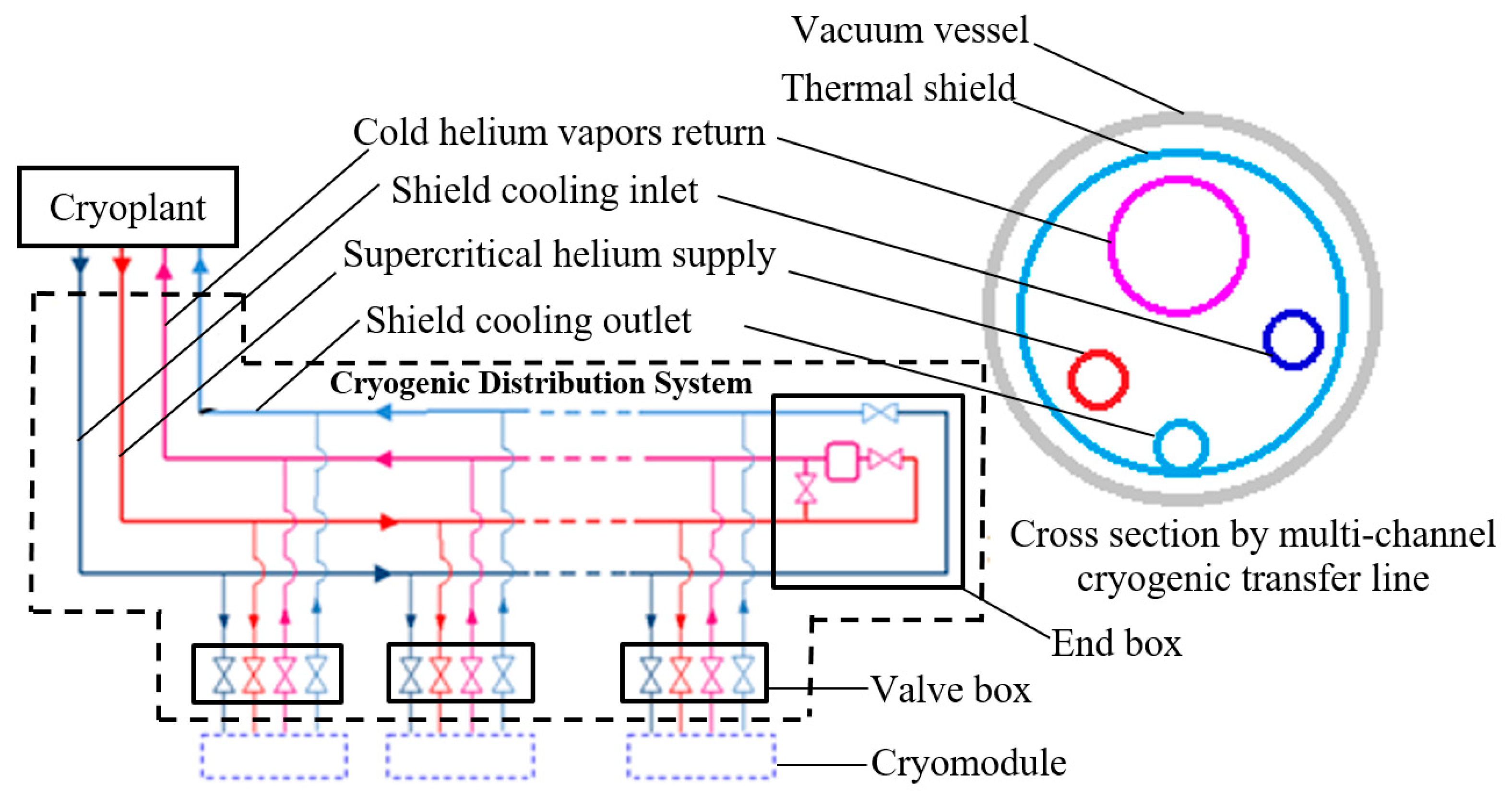
Any cryogenic system is composed of multiple interdependent subsystems that facilitate the efficient cooling, circulation, and recovery of helium as well as the safety, control, and helium storage system. Despite different functionalities, each helium cryogenic system must consist of a certain number of key elements, including the helium refrigeration and liquefaction plant (cryoplant), the cryogenic distribution system, and the cryomodules or cryostats housing superconducting devices. A general scheme of the helium cryogenic distribution system is presented in
Figure 2.
2.1. Helium Refrigeration and Liquefaction Plant (Cryoplant)
The cryoplant serves as the central component of any helium cryogenic system, providing the necessary cooling power to maintain cryogenic conditions. Its primary functions include reducing helium temperature while increasing its density. Helium exiting the cryoplant is typically in a supercritical state to avoid two-phase flows at long distances. Additionally, the cryoplant incorporates a helium recovery and storage system, enabling helium to be stored as pressurized gas during maintenance periods. A liquid helium tank is frequently included to act as a buffer, stabilizing fluctuations in cooling power.
2.2. Cryogenic Distribution System
The cryogenic distribution system transports helium from the cryoplant to the superconducting components requiring cooling. This bidirectional system facilitates both the supply of cryogen for cryostating and the return of warm helium for recooling. The primary components of the distribution system include
Cryogenic transfer lines: Multichannel insulated pipelines designed to transport helium in various thermodynamic states;
Valve boxes: Intermediate cryogenic devices equipped with measurement instruments and control valves for regulating helium flow into cryostats. The valve boxes may also comprise heat exchanges and Joule–Thomson valves, allowing for the conversion of supercritical helium to the liquid or superfluid state.
The length and configuration of the transfer line, along with the number of valve boxes, depend on the architecture of the research facility and may be of the order of several kilometres (3.4 km in the case of a single LHC sector). However, their function remains consistent, enabling precise cryogen delivery to cryomodules and removal. The system concludes with an endbox, which regulates and vaporizes unused cryogen, thereby improving system stability and operational flexibility.
2.3. Cryomodules/Cryostats
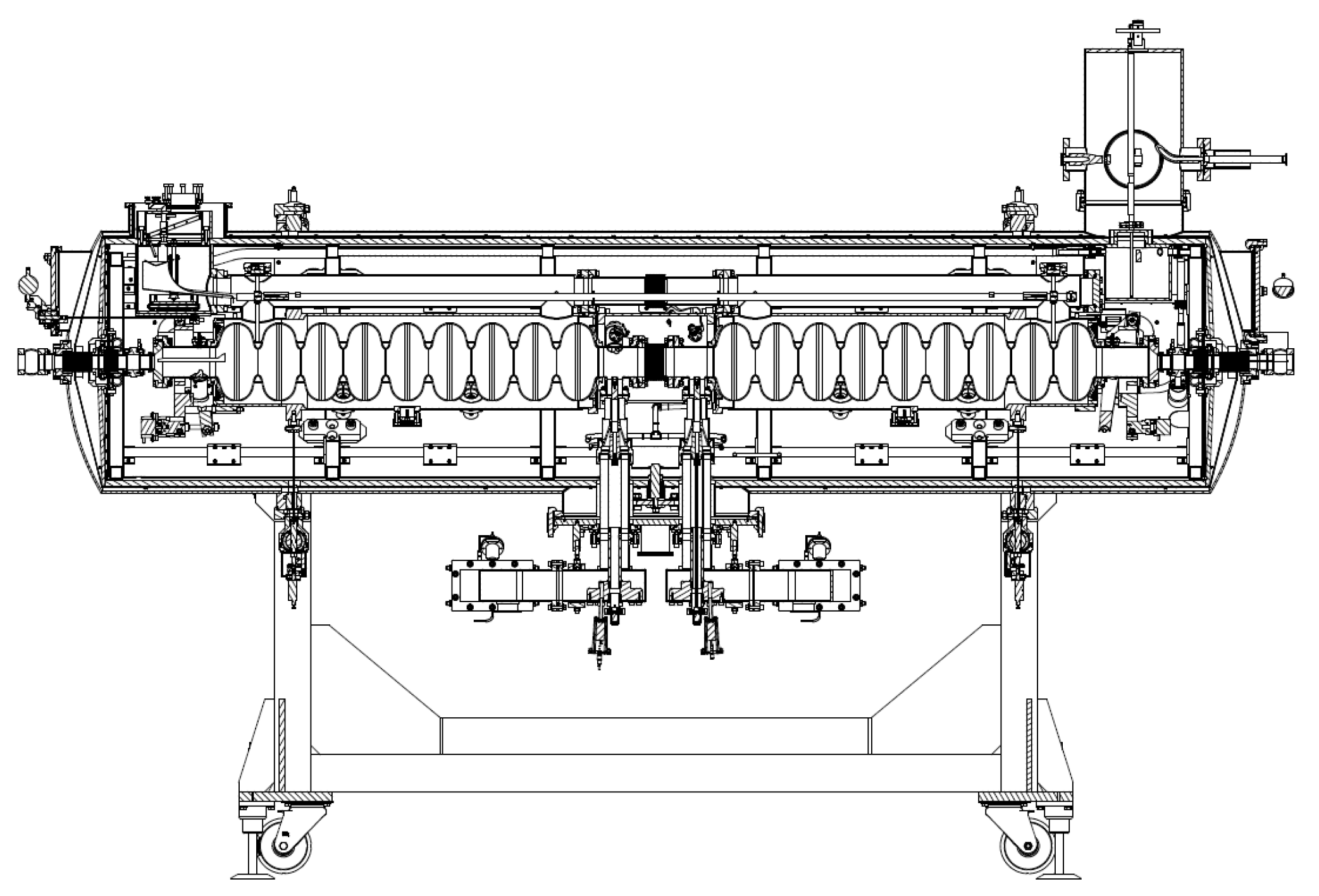
The intended destination for helium transfer through the CDS is the cryomodules or cryostats. These are cryogenic devices in which accelerator components requiring cooling to cryogenic temperatures are enclosed. Cryomodules house superconducting RF cavities, which are critical for particle acceleration. Cryostats house superconducting magnets: dipole, quadrupole magnets that are essential for beam guidance and focusing. The cross-section of a sample cryomodule is shown in
Figure 3.
The number of cryomodules and/or cryostats depends on the specific research facility and the number of superconducting components requiring cryostating. Each cryomodule or cryostat functions as an independent cooling unit within the larger cryogenic system.
Helium cryogenic systems operate in a closed-loop configuration to maximize efficiency and minimize helium losses.
The operational sequence follows these steps [
1,
2,
3,
4,
5]:
Helium is cooled and liquefied or subcooled in the cryoplant as required;
Cryogenic transfer lines transport helium to valve boxes, where precise pressure and temperature control occur;
Helium enters cryomodules to cool superconducting components by evaporation;
Helium vapour is collected and returned to the cryoplant for recompression and re-cooling;
This closed-loop cycle ensures the stable and continuous operation of the accelerator’s superconducting elements, optimizing both performance and helium utilization.
As mentioned in
Section 1, the optimal operating temperature for SRF cavities is 2 K. In cryomodules such as the one shown in
Figure 3, the cavities are cooled by submersion in saturated superfluid helium at a temperature of 1.8–2.0 K and a pressure of approximately 16 mbar(a) at 1.8 K and 31 mbar(a) at 2.0 K.
The use of helium under such conditions presents numerous engineering challenges. Helium must be transferred from the cryoplant to the cryomodules. During this process, superfluid helium requires precise control of the slope of each process pipe to prevent syphoning. Additionally, transferring helium over long distances would lead to increased losses of superfluid helium due to boil-off. Due to the challenges associated with transportation, modern cryogenic systems primarily rely on supercritical helium transfer. This method prevents unwanted phase transitions and reduces helium losses due to evaporation in the transfer line. Phase conversion from supercritical to superfluid helium occurs near the superconducting components, either within dedicated valve boxes or directly inside cryomodules. Numerous additional challenges must be addressed when designing a cryogenic system for cooling SRF cavities using this method. These include
Pressure control inside cryomodules: The cryoplant must maintain the appropriate pressure inside the cryomodules, which requires the use of vacuum pumps.
High flow resistance of helium vapour: Helium vapours returning from the cryomodule to the cryoplant are highly rarefied due to the very low operating pressure. This results in relatively high flow resistance.
Positioning of vacuum pumps: During system design, various possible positions for vacuum pumps along the transfer line are considered in order to minimize thermodynamic losses during the return flow of helium vapours.
Thermalization of power couplers: Power couplers inside the cryomodules must be cooled to different temperatures (typically around 5 K) than the resonant cavities, which presents an additional thermal management challenge.
These examples illustrate only a subset of the technical difficulties that must be addressed. Designing an efficient and reliable cryogenic system requires a comprehensive approach that takes into account many interdependent physical and engineering constraints.
3. Entropy Analysis as a Design Tool for Cryogenic Systems
The challenges involved in designing and building cryogenic systems are diverse, ranging from technical and economic issues to material selection. These challenges include ensuring precise temperatures, pressure and helium flux control, maintaining system efficiency, and ensuring long-term reliability. Entropy analysis offers a powerful tool to minimize inefficiencies and enhance system performance. It allows for a choice between different thermomechanical design patterns on the basis of energy consumption minimization. This analysis enables the evaluation of thermodynamic efficiency and identifies the most cost-effective design. By comparing the entropy generation associated with different configurations, engineers can optimize the system for operational expenses resulting from input energy requirements.
Entropy analysis can be used to optimize a very wide range of thermal flow devices [
12]. An example is the use of entropy analysis by Chen et al. [
13] to optimize radiative heat transfer between a tank and a working fluid. Another example of using the entropy minimization method to optimize heat exchangers is provided in an article by Xia et al. [
14], in which the authors analyze the effect of heat leakage on entropy generation in the heat exchange process. Johannessen and Balkan [
15,
16] also successfully use the entropy method to optimize heat exchangers. As shown by Xu et al. [
17], the method based on the second law of thermodynamics can also be applied for the multi-objective analysis and optimization of a heat engine, using the Stirling engine as an example. M. Feidt and M. Costea [
18] also use the entropy method to try to improve the efficiency of Carnot and Chambadal engines. Cryogenic systems characterized by different temperature levels, high- and low-pressure cryogen flows, and sophisticated insulation systems are specially predestined for entropy analysis during a conceptual design process.
Entropy analysis is based on the second law of thermodynamics, which states that every irreversible thermodynamic process results in an increase in entropy, requiring additional external power delivered to the system. The Gouy–Stodola theorem (Equation (1)) [
12,
19] provides a framework for calculating the additional power required to mitigate the irreversibilities accompanied by entropy growth.
where
PAD—additional power required to compensate for the irreversibilities, W;
TA—ambient temperature, K;
—entropy generation due to irreversibilities, W/K.
To minimize the additional work,
PAD, systems should exhibit minimal entropy flux due to irreversibilities,
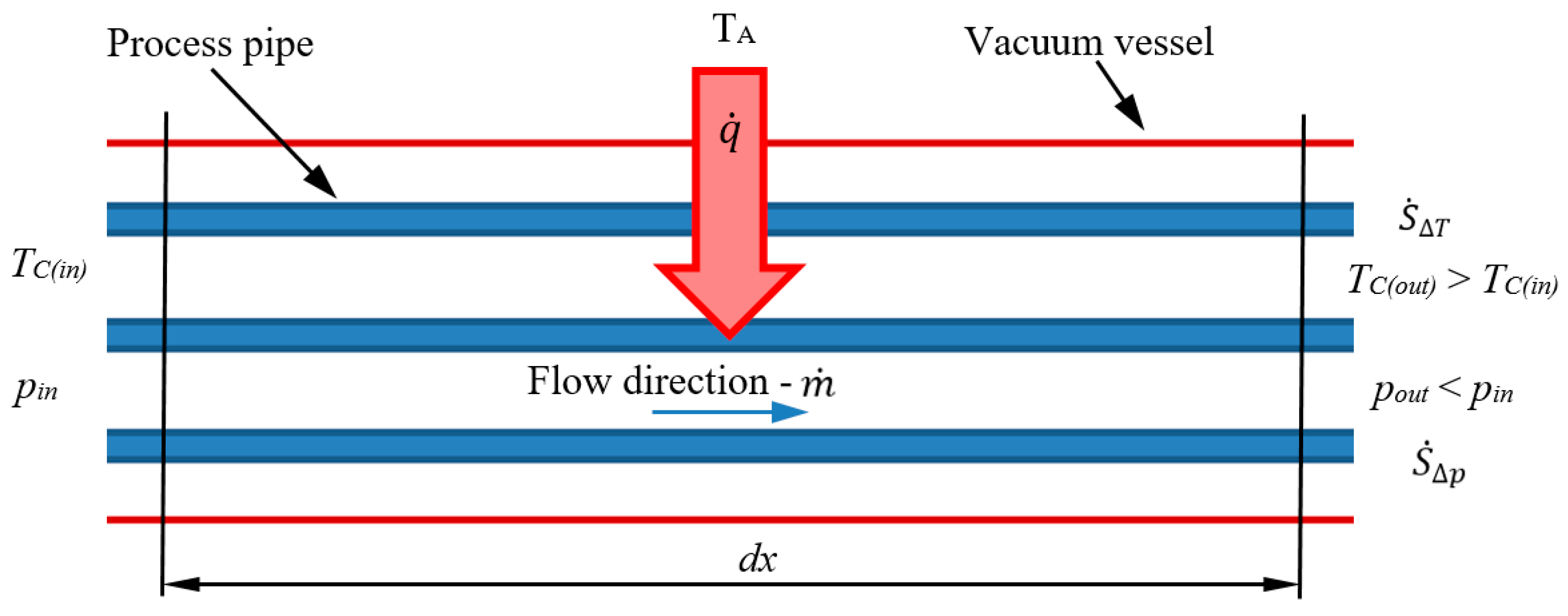
. In a cryogenic distribution system, the rise in entropy is attributed to two primary factors: the pressure drop of the medium within the process pipe and the heat exchange driven by the temperature difference between the cryogenic fluid and its surroundings—see
Figure 4. Such a defined increase in entropy can be described by Equation (2).
where
—entropy increase due to heat transfer, W/K;
—entropy increase due to pressure drop, W/K.
The entropy increase caused by heat transfer from the surroundings to the cryogen can be determined using Equation (3) [
20].
where
—heat flux, W;
TA—ambient temperature, K;
TC—temperature of cold medium, K.
Figure 4.
Processes of entropy increase in cryogenic transfer line of length dx: ṁ—mass flow rate of the transferred medium in kg/s; —heat flux in W; TC—medium temperature in K; p—pressure in Pa; indexes in—input value and out—output value.
Figure 4.
Processes of entropy increase in cryogenic transfer line of length dx: ṁ—mass flow rate of the transferred medium in kg/s; —heat flux in W; TC—medium temperature in K; p—pressure in Pa; indexes in—input value and out—output value.
The entropy increase resulting from the pressure drop during the cryogen′s flow through the pipeline can be calculated using Equation (4).
where
—helium flux, kg/s;
T—mean medium temperature, K;
ρ—mean medium density, kg/m3;
Δp—flow pressure drop in the pipeline, Pa.
Each process pipe can be composed of multiple linear pieces, elbow pieces, etc. The fluid flow pressure drop,
in a given piece can be calculated from Equation (5):
where
—local pressure drop coefficient of the piece, dimensionless;
v—fluid velocity, m/s;
d—internal diameter of the pipe, m;
—linear pressure drop coefficient, dimensionless;
L—length, m.
For the linear pipe pieces, the
values are calculated from the Haaland Equation (6):
where
—inner wall roughness, m;
Re—Reynolds number, dimensionless.
The Reynolds number is calculated from Equation (7):
where
—dynamic viscosity of the fluid, Pa.s.
The fluid velocity in the circular pipe can be calculated using Equation (8):
where
—internal cross-section of a circular pipe piece, m2.
In the case of the elbows and T-connections, the pressure drop is calculated using Equations (9) and (10) [
21]:
where
The local pressure drop coefficient of the fitting is ξ [
21]:
For elbows, ξ = 20Ft;
For T-Joint straight connections, ξ = 20Ft;
For T-Joint branched connections ξ = 60Ft.
Entropy analysis performed in this way is a valuable tool for optimizing cryogenic systems. Using the second law of thermodynamics helps identify areas of inefficiency and ensures improvements in energy utilization and system efficiency. This approach ensures that the design and operation of cryogenic systems are both effective and efficient, meeting the complex requirements of cryogenic projects. Entropy analysis has been successfully used in the design process of the PolFEL free-electron laser cryogenic system. It has been used to rationalize the choice between a number of design options, allowing for the cooling power of the cryoplant to be kept within the specification range.
4. PolFEL Cryogenic System—Architecture and Challenges
One of the advanced cryogenic systems that aligns with the general principles discussed in the previous sections is the system designed for the Polish Free-Electron Laser (PolFEL).
A free-electron laser (FEL) is a powerful research tool that merges the capabilities of conventional lasers and synchrotrons. It produces high-intensity, coherent light pulses across a broad wavelength range, from terahertz radiation to X-rays. The core components of an FEL include an electron source, an accelerator that generates a high-quality electron beam, and a sequence of undulators that impose a periodic magnetic field, causing the electrons to emit synchronized radiation. This emitted light is used in scientific experiments, while the electron beam itself can be repurposed for generating neutrons or producing ultra-short X-ray pulses. FELs play a crucial role in modern research, enabling breakthroughs in physics, chemistry, and biology. Their ability to produce intense, ultra-short pulses allows scientists to capture rapid processes at the atomic and molecular scales. These lasers facilitate high-resolution imaging of nanostructures, support pump–probe experiments to analyze the electronic properties of materials, and even create extreme states of matter, such as high-energy plasmas. Additionally, FEL-based electron beams open new possibilities for nuclear and materials science studies.
The Polish Free-Electron Laser facility project is being developed through the collaboration of eight leading Polish research institutions, with the National Centre for Nuclear Research (NCBJ) coordinating the effort. Wrocław University of Science and Technology is responsible for designing and implementing the cryogenic infrastructure. The project was launched in 2019, with the facility being constructed at the NCBJ campus in Otwock–Świerk, near Warsaw. PolFEL will be the first free-electron laser facility constructed in Poland. The facility is planned to be implemented in two distinct construction stages. During the initial phase, the setup will comprise a superconducting linear accelerator incorporating an electron gun and four cryomodules with an RI-HZDR design. Each of these cryomodules will house two nine-cell superconducting TESLA-type radiofrequency cavities. This configuration enables the generation of both continuous-wave (CW) and long-pulse electron beams. The system will support electron energies ranging from 5 to 50 MeV in CW mode and up to 187 MeV in long-pulse mode, with photon emission covering wavelengths from the terahertz (THz) regime down to 55 nanometers.
In the subsequent phase, the accelerator will be extended by the addition of two further cryomodules, increasing the maximum achievable electron beam energy to 300 MeV. This enhancement will allow for the generation of radiation in the extreme ultraviolet (EUV) spectral range, thereby significantly expanding the experimental capabilities of the facility [
22,
23,
24].
Despite the small size of PolFEL relative to the installations built and used in large research centres such as CERN, ESS, EXFEL, or Fermilab [
25,
26,
27,
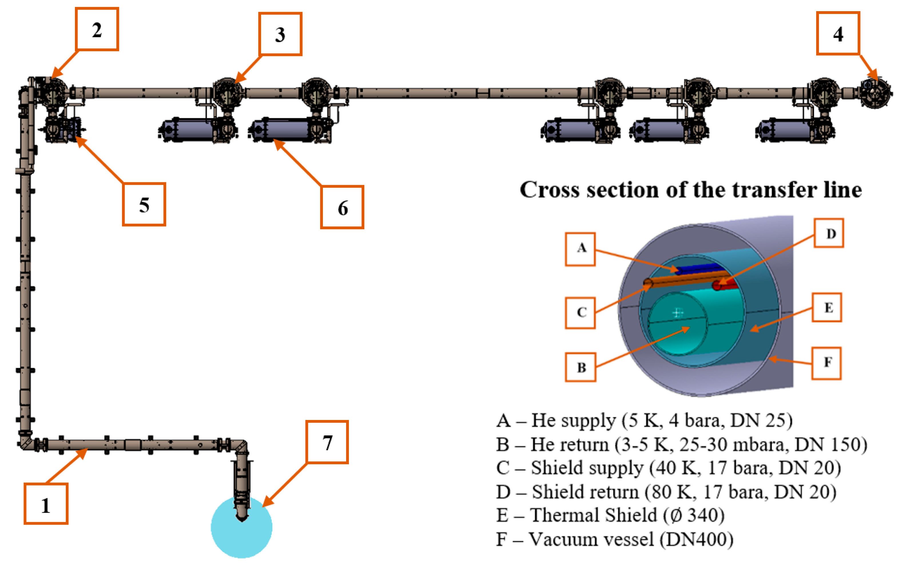
28], PolFEL will comprise all the basic elements of the cryogenic system, which allows for the use of RF resonant cavities cryostated at 2 K. The architecture of the PolFEL cryogenic system is schematically shown in
Figure 5.
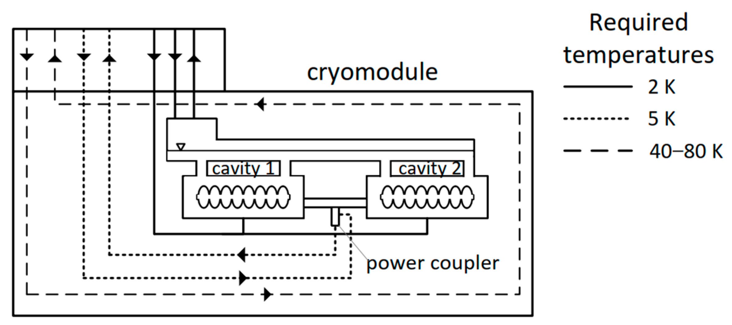
Each PolFEL cryomodule requires helium streams with varying temperatures to cool its individual components to the appropriate temperatures to achieve efficient cooling of superconducting cavities:
2 K—used for cryostating the superconducting RF cavities;
5 K—used for thermal shielding to intercept heat from power couplers;
40–80 K—used to cool thermal shields and intercept heat from room-temperature components.
A schematic view of the cryomodule with marked pipes (lines) indicating the required helium streams at specified temperatures is shown in
Figure 6.
The cryomodules in the PolFEL system are independent cryogenic units and will be cooled in parallel with the use of a cryogenic distribution system. They will be supplied with cryogen from dedicated valve boxes.
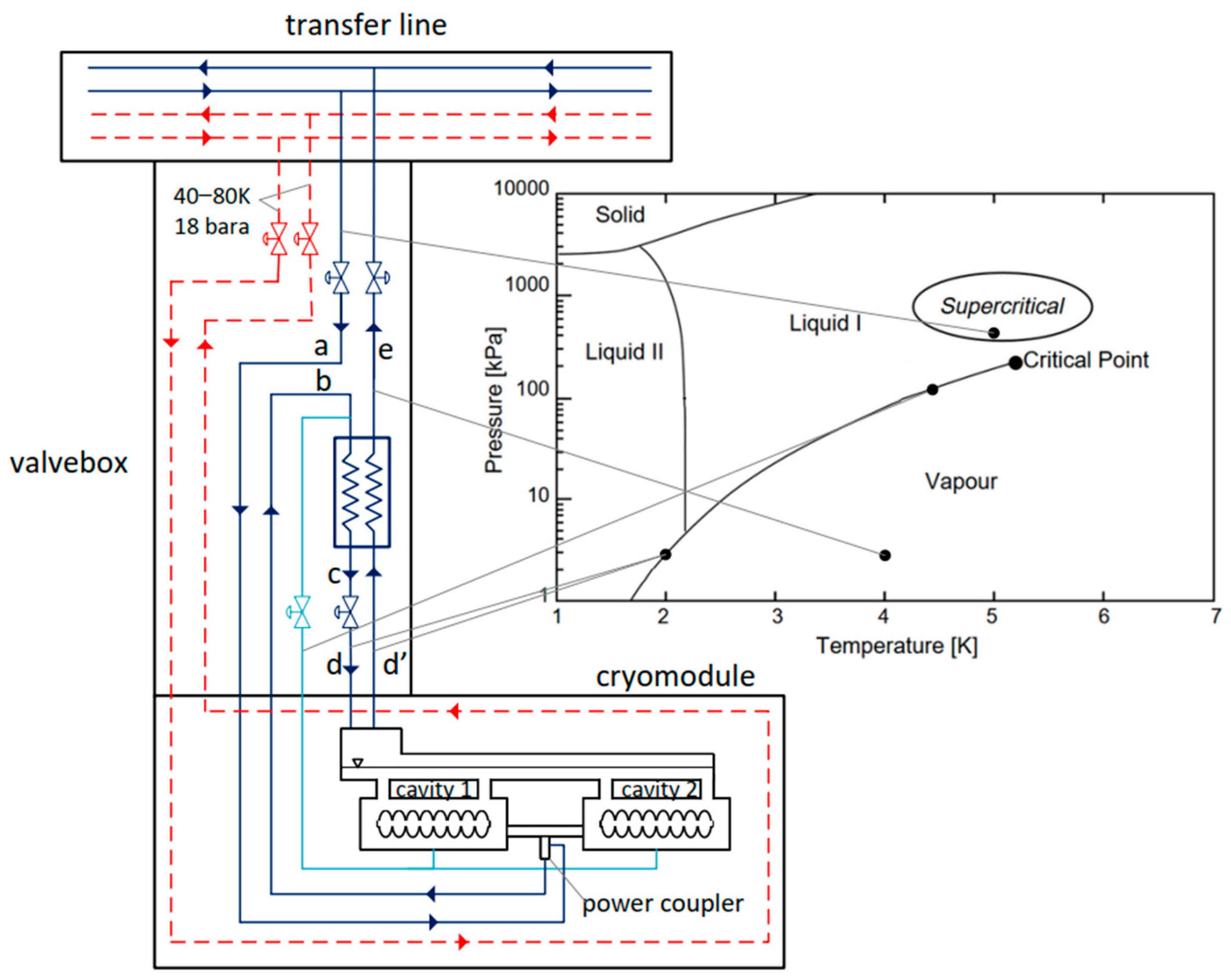
The cryoplant will provide helium to the cryogenic distribution system in two thermodynamic states: supercritical (5 K, 4 bar(a)) and cold gaseous state (40 K, 13 bar(a)). Helium gas will be used to cool the thermal shields of the cryomodules and the distribution system itself. The superfluid 2 K helium, which is required to cryostate the superconducting cavities, will be generated inside the valve boxes dedicated to each cryomodule.
The cryomodules’ cavities will be cooled in the following manner: supercritical helium will be supplied from the cryoplant, through the transfer line, and into the valve boxes dedicated to each cryomodule. Inside the valve boxes, the helium flux will be redirected from the main transfer line. Supercritical helium will first be delivered to the cryomodules (line “a” in
Figure 7) to thermalize the power couplers at a temperature of 5 K. After the thermalization process, supercritical helium will flow back to the valve boxes (line “b” in
Figure 7), in which it will be pre-cooled to 2.2 K in a heat exchanger (line “c” in
Figure 7) and subsequently throttled in the JT valve into a superfluid state (2 K and 30 mbar(a)) required to cryostate the SRF cavities (line “d” in
Figure 7). The superfluid helium thus obtained will be transferred to the cryomodules, in which it will vaporize, receiving the heat generated by the cooled elements. After being vaporized, helium at a pressure of 30 mbar(a) and a temperature of 2 K will flow back to the valve boxes (line “d” in
Figure 7). It will subsequently pass through the low-pressure part of the heat exchanger (line “e” in
Figure 7) and, finally, through the transfer line to the cryoplant. Helium vapours are then returned to the cryoplant under a pressure of approximately 27 mbar(a) and at a temperature of approx. 4 K. Subsequently, they are compressed to approx. 0.3 bar(a) with the use of cold compressors located in the cold box of the cryoplant. Such a solution will allow the cooling capacity of cold helium vapours to be recovered before their compression to atmospheric pressure in the set of warm vacuum pumps.
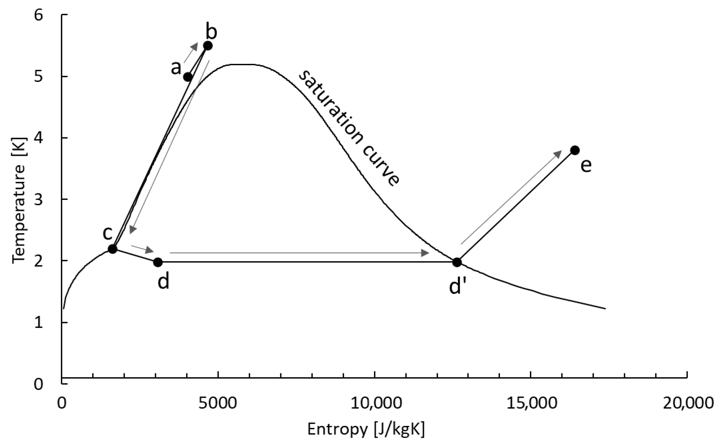
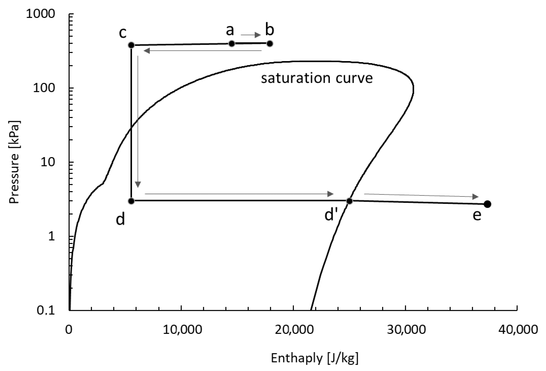
Figure 8 and
Figure 9 schematically show the cooling system of the cryomodule cavities, in the T-S and logP-H diagrams, respectively.
5. Entropy Analysis of Chosen Design Options for PolFEL CDS Elements
The design of cryogenic systems for particle accelerators presents a significant challenge in low-temperature engineering. Although PolFEL is a relatively short accelerator compared to large-scale installations, its cryogenic system includes all the key components outlined in
Section 2. As a result, the design challenges encountered in this cryogenic system mirror those of large-scale cryogenic installations, even if on a smaller scale.
This paper focuses on two exemplary challenges addressed in the development of the cryogenic system for the PolFEL cryogenic system:
5.1. Power Coupler Cooling Method
Each accelerating cryomodule will consist of two TESLA cavities equipped with a power coupler (see
Figure 6), which must be maintained at a temperature of 5 K for optimal operation [
29]. Consequently, developing a method for effectively removing heat from these components has become imperative. The cryomodule design incorporates an additional cooling loop to supply and remove cryogenic fluid to and from the power couplers. Therefore, during the design phase of the cryogenic distribution system, it was essential to consider the requirement of providing cooling power to these elements. For this purpose, three concepts for the cooling of power couplers were developed. The final selection was made based on an entropy analysis of each of the proposed methods.
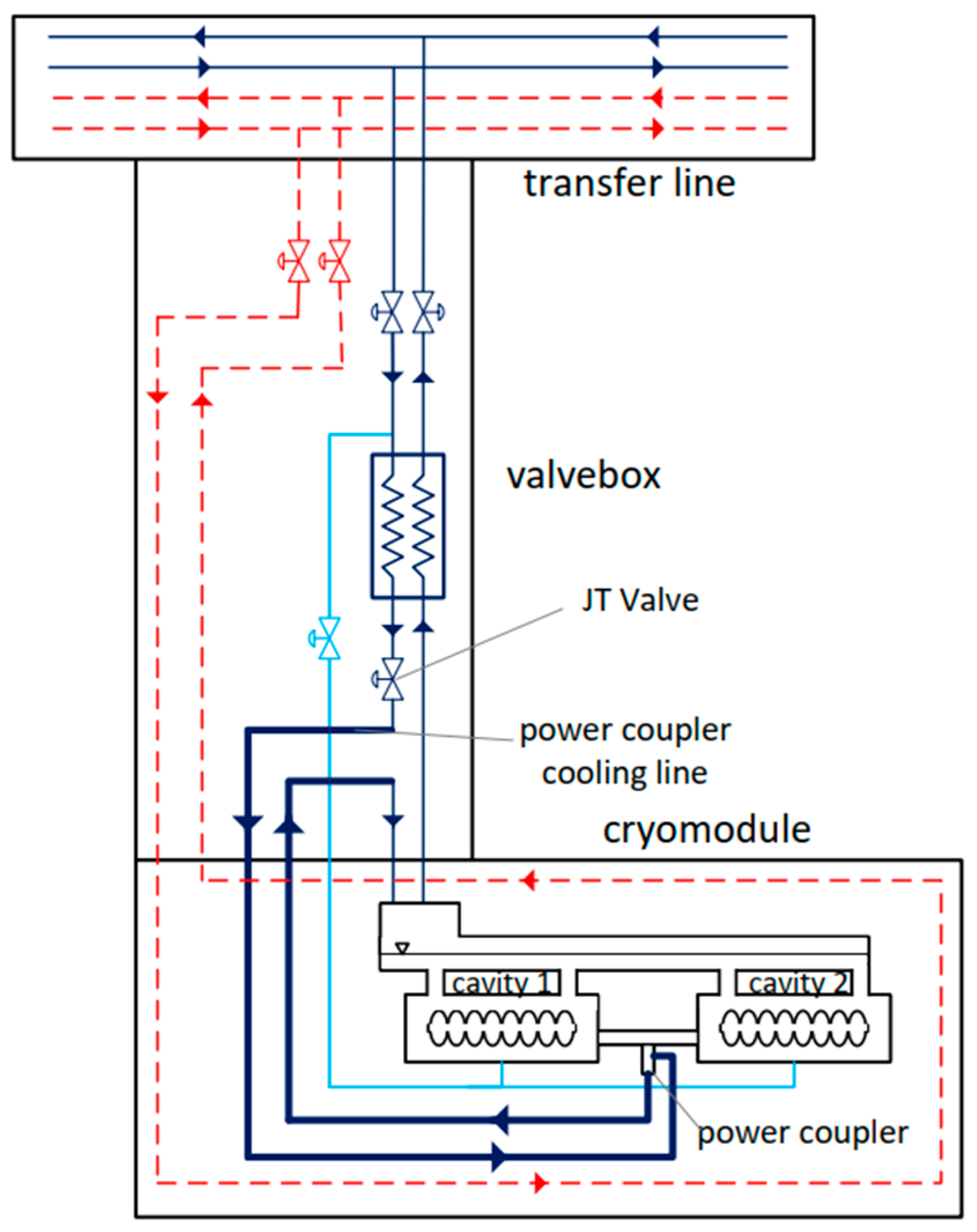
Structurally, the simplest solution involves cooling the power coupler using superfluid helium generated in the valve boxes, with a separate system for each cryomodule. In this process, supercritical helium is transferred from the refrigerator and cooled in the heat exchanger within the valve box. Subsequently, it is throttled in the Joule–Thomson (JT) valve, resulting in a vapour–superfluid mixture. This mixture is then transported to the cryomodule to cool the power coupler. Following the removal of heat from the power coupler, the mixture is directed to a superfluid helium tank located within the cryomodule, which is utilized to cryostate the superconducting radiofrequency (SRF) cavities. This approach is shown in
Figure 10.
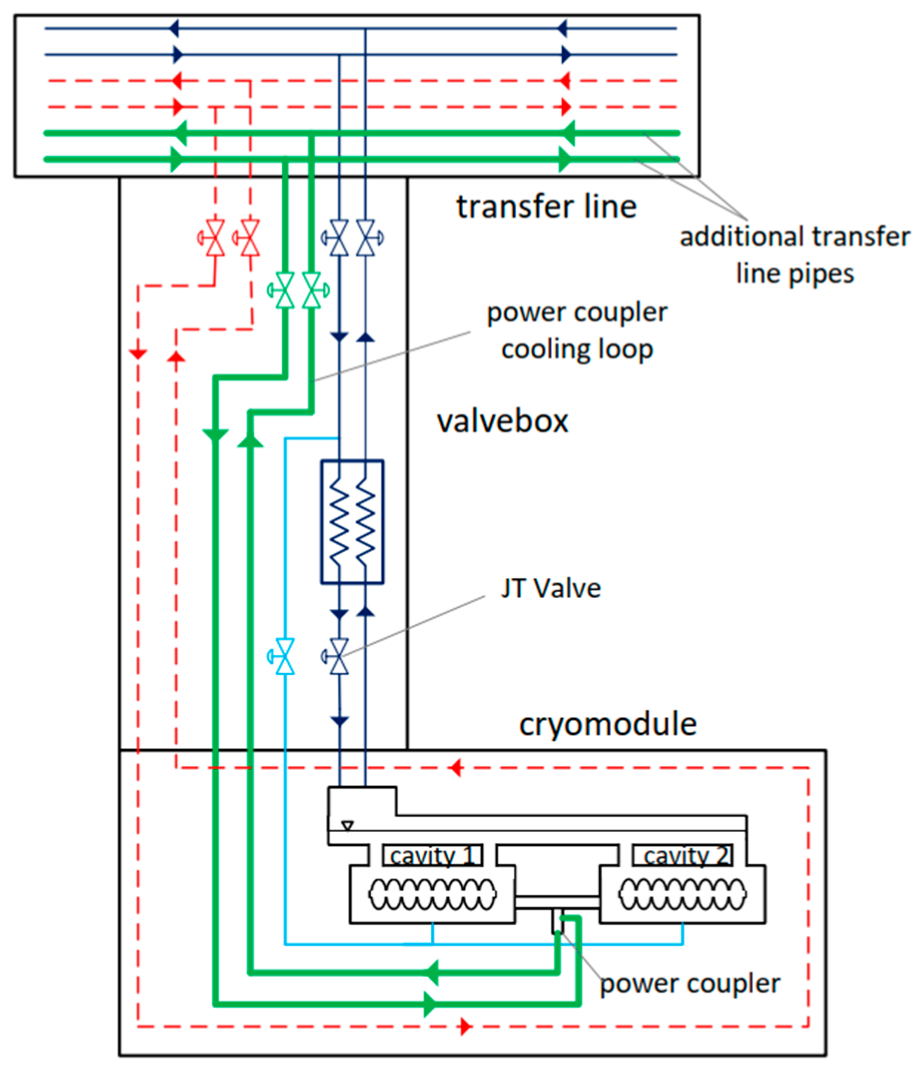
In the second solution, a dedicated cooling loop is incorporated into the transfer line to facilitate the supply and removal of supercritical helium, which is utilized exclusively for the cooling of the power couplers. The cooling loop for the power coupler, situated within the cryomodule, is connected to the additional supply and return lines through a connection that traverses the valve box, as illustrated in
Figure 11.
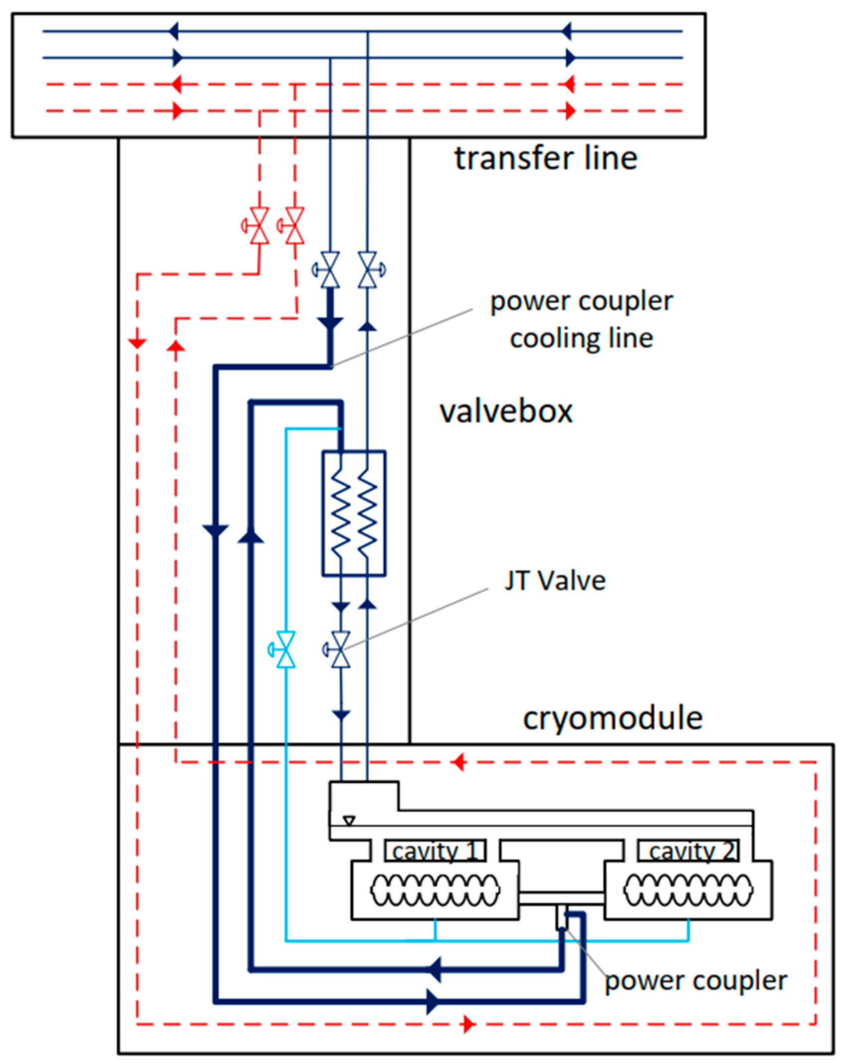
The third solution involves cryostating the power couplers using the same flow of supercritical helium that will be utilized to cryostate the superconducting radiofrequency (SRF) cavities after it has been cooled in the heat exchanger and throttled. For this purpose, a connection will be established within the valve box between the supply line delivering supercritical helium to the heat exchanger and the cooling loop of the power couplers. Initially, the supercritical helium will be employed to cool the power coupler before being directed to the heat exchanger and JT valve, where it will be throttled to achieve a vapour–superfluid mixture. This approach is shown in
Figure 12.
An entropy analysis was employed to select the optimal cooling method for power couplers, as described in
Section 3. To this end, heat inflows and pressure losses in the cooling fluid flow of the power couplers were estimated. Given the repetitive structure of the accelerator, only the first cryomodule and its associated power coupler were considered during the analysis. The results obtained from the first power coupler are representative of the remaining part of the cryogenic distribution system. The following procedure was used to determine the entropy fluxes generated in the multichannel transfer line and between the valve box and the coupler. To determine the entropy flux generated in the transfer line for a single power coupler, the total entropy flux for the process line corresponding to the entire mass flow in the specific design case was calculated. Subsequently, based on the cooling fluid demand for the individual power coupler, the entropy flux attributable to a single power coupler was established. In the next step, the entropy flux for the individual power coupler was determined based on the heat inflows and pressure drops during the flow between the valve box and the power coupler. A comprehensive summary of the results from the entropy analyses for each design case is presented in
Table 1.
Table 1 illustrates the values of the entropy fluxes based on their sources—heat inflows and pressure drops. It can be observed that heat inflows play a dominant role in each case.
In the case shown in
Figure 10, in which a mixture of vapour–superfluid helium is utilized for the cooling of the power coupler, only the entropy flux generated due to heat inputs was determined, owing to the two-phase flow. The determination of the entropy flux based on the pressure drop during two-phase flow is associated with a significant degree of calculation error; thus, this parameter was omitted. Simultaneously, due to the lowest temperature of the coolant in this instance, the entropy flux generated as a result of heat inputs is twice that of the fluxes in the other computational cases, even when pressure drops are taken into account. Therefore, the first design case can be dismissed solely based on the value of the entropy flux generated due to heat inputs.
Using the input parameters given in
Table 1, the entropy fluxes generated as a result of heat inputs and pressure drops can be determined for each of the analyzed design cases for power coupler cooling, as derived from Equations (1) and (3), and the additional power (P
AD) necessary to overcome the irreversibilities accompanying the flow can be determined [
30,
31].
To ascertain the actual additional power required to overcome the described irreversibilities (
PADR), it is essential to consider the thermodynamic efficiency of the cryogenic refrigerator, which, as indicated in
Section 1, is 0.3 in terms of the Carnot efficiency. The values of the additional power (
PAD) and the actual additional power (
PADR), determined based on the total entropy fluxes generated for each design case, are presented in
Table 2.
Analyzing the results of the entropy analysis presented in
Table 1, it can be noted that the cooling solutions for power couplers utilizing supercritical helium are similar in terms of the actual additional power required to be supplied to the helium refrigerator. The solution based on cooling power couplers with helium transported through a separate process pipe loop was found to be slightly thermodynamically inferior to the solution involving the use of a typical transmission line for transporting supercritical helium used to cool power couplers and SRF cavities.
The primary difference between the solutions shown in
Figure 11 and
Figure 12 lies in the higher heat inleaks in the transfer line to the separate loop transporting supercritical helium to cool the power couplers. Furthermore, this solution is also disadvantageous from a structural perspective, as the introduction of two additional process pipes significantly complicates the cross-section of the multichannel transfer line, resulting in more challenging support configurations for all process pipes and increased complexities during construction and assembly.
Therefore, based on the entropy analysis of design and execution costs, the cooling solution for power couplers presented in
Figure 12 was selected. This solution involves the initial use of supercritical helium for cooling the power couplers, after which the same helium flow will be directed through a heat exchanger and a J-T valve to achieve a vapour–superfluid mixture for cooling the SRF resonant cavities.
5.2. Placement of Cold Compressors
The second engineering challenge encountered during the development of the PolFEL cryogenic infrastructure was the optimal placement of cold compressors. While the overall compression strategy—a hybrid approach utilizing both cold compressors and warm vacuum pumps—had been selected, the specific location of the cold compressors within the facility remained a subject of detailed entropy-based analysis.
The operation of the cryoplant is directly related to the helium parameters, which need to be maintained during the standard operation of the cryomodules. The superconducting RF cavities in PolFEL will operate at approximately 2 K, immersed in saturated superfluid helium (see
Figure 1). All of the heat generated by the cavities and the heat inleaks from the environment will be compensated for by helium vaporization. The vaporized helium, characterized by low temperature and pressure, must then be returned to the cryoplant for reprocessing into dense, high-pressure supercritical helium at around 5 K.
In the selected compression scheme, cold compressors are employed upstream of the warm vacuum pumps to recover cold exergy and reduce the volumetric demands on the vacuum pumps [
32]. This pre-compression step allows for more efficient use of the initial stages of the cryoplant’s heat exchangers and helps minimize entropy generation associated with warming low-pressure helium [
33].
However, implementing cold compressors introduces a key design decision: should they be located in the cryoplant hall, adjacent to other major cryogenic infrastructure, or closer to the accelerator tunnel, approximately 25 m away from the cryoplant hall, where the helium vapours originate? The two considered solutions are presented in
Figure 13.
Each configuration has distinct thermodynamic and engineering trade-offs. Locating the cold compressors in the cryoplant hall simplifies integration, reduces service complexity, and centralizes cryogenic equipment. However, it may lead to increased entropy generation due to longer low-pressure vapour transfer lines exposed to heat loads. Conversely, placing the compressors closer to the accelerator tunnel minimizes those transfer losses and enhances cold exergy utilization but introduces challenges related to noise, vibration isolation, and spatial constraints in the technical area adjacent to the tunnel.
To resolve this dilemma, an entropy-based analysis of the helium vapour return line was conducted using the previously described algorithm. The analysis was based on the following assumptions:
Length of the Transfer Line—25 m;
Number of elbows—10 pcs;
Pipe size upstream of the cold compressors—DN150;
Pipe size downstream of the cold compressors (if the cold compressors are placed near the accelerating hall)—variable (DN50, DN80, DN150);
Heat flux to helium (average)—0.25 W/m2;
Flow rate—29.5 g/s;
Pressure of helium in the transfer line leaving the accelerating hall—0.029 bar(a);
Temperature of helium in the transfer line leaving the accelerating hall—4.2 K;
The temperature of helium after the cold compressors is calculated in the adiabatic compression process;
Pressure of helium after the cold compressors—0.3 bar(a).
Similarly to the previous calculations, the actual additional power required to overcome the described irreversibilities (P
ADR) was calculated using an efficiency of 0.3, the Carnot efficiency. The values of the additional power (P
AD) and the actual additional power (P
ADR), determined based on the total entropy fluxes generated for each design case, are presented in
Table 3.
As expected, the smallest entropy generation due to the pressure drop was associated with flow through pipes of larger diameters, while the smallest entropy generation due to the temperature difference was associated with flow through pipes of smaller diameters. Due to the higher costs associated with this non-standard configuration, it was anticipated that significant savings could be achieved by reducing the pipe diameter. For a pipe with a DN80 diameter, the reduction in additional power due to lower entropy generation was found to be approximately 0.2 kW. This value was not significant enough to justify the unconventional placement of the compressors. Consequently, it was decided to locate the cold compressors inside the cryoplant building.
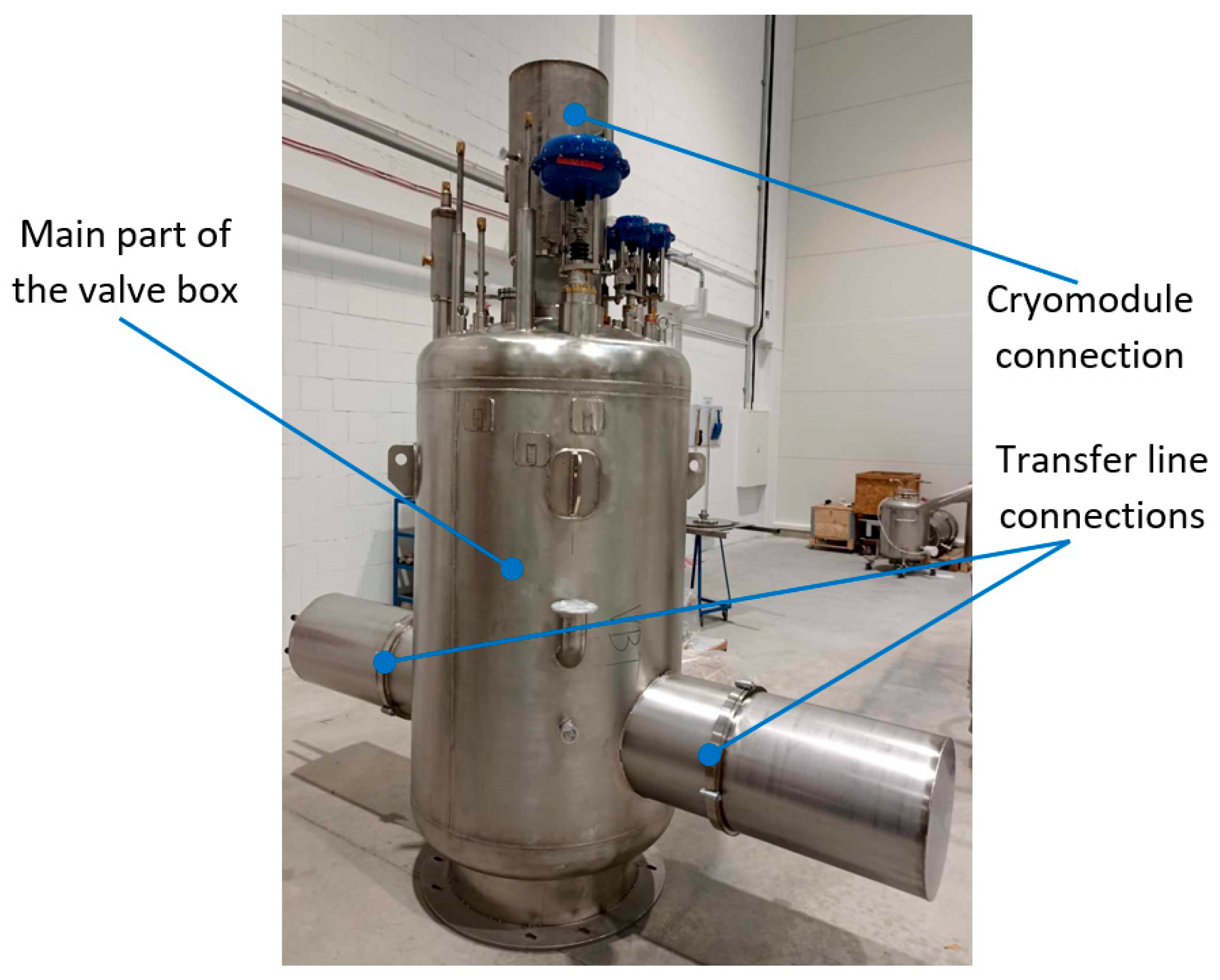
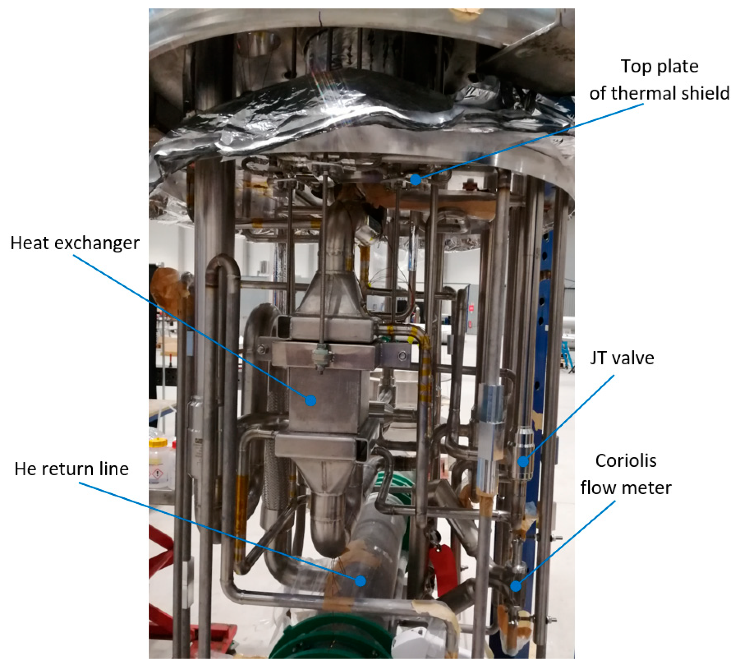
The design and optimization process must consider not only key parameters, such as the required cooling power and helium conditions necessary for the proper operation of the resonant cavities, but also practical constraints, including the facility′s location and the available space for system installation. An example of such a challenge was the need to reduce the external dimensions of the devices that were part of the CDS. As a result, the dimensions of the vacuum tanks in the valve boxes were limited, and thus the cryogenic equipment—valves, compensation elements and flowmeters—were densely packed. The internal structure and vacuum vessel of an example valve box from the cryogenic distribution system for the PolFEL are shown in
Figure 14 and
Figure 15.
As a result, the production, welding, and assembly required high precision, and the process pipes had to be accurately arranged.
6. Conclusions
This work presents a design approach for the helium cryogenic distribution system of the Polish Free-Electron Laser (PolFEL) facility, with a focus on the use of entropy-based analysis for system optimization. Although the PolFEL system is smaller in scale than installations at large international laboratories, it features many similar structural, operational, and thermodynamic challenges. The presented methodology is based on the second law of thermodynamics and provides a practical tool for guiding design decisions related to fluid flow, temperature management, and energy efficiency in cryogenic environments.
A summary of the study’s key outcomes is presented below:
The architecture of the PolFEL cryogenic distribution system was adapted to spatial and technical constraints, while ensuring the delivery of helium at various required temperature levels (2 K, 5 K, and 40–80 K).
An entropy-based comparative analysis of three power coupler cooling options revealed that using a single flow of supercritical helium—first to cool the power coupler, then throttled to cryostate SRF cavities—was the most thermodynamically and structurally effective solution.
The placement of cold compressors was analyzed with respect to entropy generation and practical feasibility. Locating them within the cryoplant building was found to be optimal, considering both thermodynamic and construction aspects.
In addition to the direct design outcomes, this study offers methodological insights that may be valuable for future cryogenic system designs. The entropy-based evaluation framework enables an objective, thermodynamically grounded comparison of alternative system configurations and supports early design decision-making, particularly where multiple subsystems interact.
However, several limitations of the current work should be noted:
The entropy analysis shown in this paper is based on steady-state conditions; transient effects and system dynamics (e.g., cooldown/warm-up phases) were not included.
The treatment of two-phase flow pressure drops was simplified;
Economic and practical assembly constraints were only partially considered in the thermodynamic assessment.
As is standard for unique cryogenic systems, the PolFEL design demands a tailored approach due to its specific geometry and helium flow requirements. Addressing various challenges—including material strength, safety considerations, and the constraints of manufacturing and assembling valve box components within a limited space—was crucial in the system’s development.
