Systematic Review

A Systematic Review of Two-Phase Expansion Losses: Challenges, Optimization Opportunities, and Future Research Directions

by
Muhammad Syaukani
1,2,
Szymon Lech
2,
Sindu Daniarta
2,* and
Piotr Kolasiński
2,*
1
Department of Mechanical Engineering, Institut Teknologi Sumatera, Bandur Lampung 35365, Indonesia
2
Department of Thermodynamics and Renewable Sources, Wrocław University of Science and Technology, Wybrzeże Wyspiańskiego 27, 50-370 Wrocław, Poland
*
Authors to whom correspondence should be addressed.
Energies 2025, 18(13), 3504; https://doi.org/10.3390/en18133504
Submission received: 8 May 2025 / Revised: 10 June 2025 / Accepted: 30 June 2025 / Published: 2 July 2025
(This article belongs to the Special Issue Design and Experimental Study of Organic Rankine Cycle System)

Abstract

Two-phase expansion processes have emerged as a promising technology for enhancing energy efficiency in power generation, refrigeration, waste heat recovery systems (for example, partially evaporated organic Rankine cycle, organic flash cycle, and trilateral flash cycle), oil and gas, and other applications. However, despite their potential, widespread adoption is hindered by inherent challenges, particularly energy losses that reduce operational efficiency. This review systematically evaluates the current state of two-phase expansion technologies, focusing on the root causes, impacts, and mitigation strategies for expansion losses. This work used Preferred Reporting Items for Systematic Reviews and Meta-Analyses (PRISMA). Using the PRISMA framework, 52 relevant publications were identified from Scopus and Web of Science to conduct the systematic review. A preliminary co-occurrence analysis of keywords was also conducted using VOSviewer version 1.6.20. Three clusters were observed in this co-occurrence analysis. However, the results may not be significant. Therefore, the extended work was done through a comprehensive analysis of experimental and simulation studies from the literature. This study identifies critical loss mechanisms in key components of two-phase expanders, such as the nozzle, diffuser, rotor, working chamber, and vaneless space. Also, losses arising from wetness, such as droplet formation, interfacial friction, and non-equilibrium phase transitions, are examined. These phenomena degrade performance by disrupting flow stability, increasing entropy generation, and causing mechanical erosion. Several losses in the turbine and volumetric expanders operating in two-phase conditions are reported. Ejectors, throttling valves, and flashing flow systems that exhibit similar challenges of losses are also discussed. This review discusses the mitigation and the strategy to minimize the two-phase expansion losses. The geometry of the inlet of the two-phase expanders plays an important role, which also needs improvement to minimize losses. The review highlights recent advancements in addressing these challenges and shows optimization opportunities for further research.

1. Introduction

A growing interest in the use of renewable energy sources, such as solar thermal, geothermal, ocean thermal, and industrial waste heat, confronts challenges due to fluctuation and intermittent conditions, which limit their ability to produce electricity reliably using conventional energy conversion technologies. To overcome these constraints, innovative approaches like the use of the two-phase expansion process have emerged [1,2], which enables the direct conversion of unstable or low-grade heat into usable energy. The two-phase expansion process can also be applied in the organic Rankine cycle (ORC) [3] in which the configured system refers to a partially evaporated ORC [4], trilateral flash cycle [5], or organic flash cycle (OFC) [6]. However, conventional turbomachinery often avoids two-phase expansion due to several challenges, such as blade erosion caused by the liquid droplet impact during rapid pressure drops and uneven fluid interactions. Recent studies propose a solution to this issue by replacing turbomachinery with volumetric expanders such as scroll, screw, or other rotary expanders [1,2]. These devices are likely suitable for handling two-phase flows because of their compact design, low rotational speed, and high expansion ratio [7]. Nevertheless, these volumetric expanders have drawbacks, which include some internal leakage, dead volume, pressure pulsations, and limited output power [8].
Volumetric machines such as pumps, compressors, and expanders share common design principles. For instance, innovations in sealing mechanisms, lubrication strategies, and leakage mitigation developed for pumps can possibly be adopted to enhance the reliability and operating conditions of volumetric expanders. This adaptability allows volumetric expanders to handle working fluids across volume fraction ratios, which makes them suitable for handling two-phase expansion processes.
Furthermore, other components and systems handling phase-changing flows face challenges. Ejectors [9], for example, which recover energy from high-pressure streams to entrain and compress low-pressure fluids, encounter mixing losses and shock waves when handling two-phase flows. These inefficiencies arise from imperfect phase interaction and momentum transfer, particularly under off-design conditions. In flashing flow systems [10], where liquid undergoes sudden vaporization (e.g., in a geothermal power system), challenges such as cavitation, phase separation, and uneven density distribution can lead to mechanical damage and efficiency losses. These phenomena mirror the issues observed in two-phase expanders, where non-equilibrium phase changes [11] and inhomogeneous fluid interactions contribute to blade erosion or rotor wear. Recent refrigeration research focuses on cutting throttling losses by replacing the traditional expansion valve with either a two-phase expander or an ejector. A two-phase expander turns the pressure drop into usable shaft power, but suffers from mechanical complexity; its rotors and seals wear out quickly in a wet environment. An ejector, by contrast, relies on a high-speed jet from the motive flow to entrain and compress the low-pressure, two-phase suction stream, and it has no moving parts. This makes ejectors robust, inexpensive, and able to handle liquid droplets. However, because the combined stream must pass through a normal shock, an ejector recovers only part of the pressure exergy.
The development of a two-phase expansion process could accelerate the advancement of energy conversion systems that harness intermittent and fluctuating low-grade heat sources, such as industrial waste, solar thermal, and so on. In 1999, Smith [12] presented a brief review on the development of two-phase expanders for application in energy recovery, such as geothermal systems, heat pumps, refrigeration, and so on. In 2021, a preliminary study [13] discussed the application of two-phase volumetric expanders in an ORC system, but there was a lack of experimental validation. In 2022, Heule et al. [1] and Francesconi et al. [2] reviewed the potential application of two-phase volumetric expanders in several applications. Some performance assessments were reviewed. However, despite their potential, two-phase expansion in volumetric machines, ejectors, and throttling valves may face several losses. Performance losses such as mechanical inefficiencies, thermodynamic irreversibilities, losses due to wetness, and other losses often arise during two-phase operations. There is a lack of studies on these losses, and to the authors’ knowledge, no systematic literature review exists to gather existing findings and identify effective mitigation strategies.
This study aims to address this gap by providing a review of performance losses in two-phase volumetric expanders. This review identifies key losses and evaluates proposed solutions by systematically analyzing existing literature, which are the objectives of this work. Some losses from ejectors, throttling valves, and other technologies related to the expansion process or flashing flow are also discussed. In this way, a similar approach to countermeasures to reduce losses may be used for volumetric expanders. Moreover, it highlights the impact and the future direction of the research on this topic. The presented review aims to guide the development of a high-efficiency two-phase volumetric expander in the future.

2. A Methodology of Review

This literature review employs a systematic, structured methodology to identify, screen, evaluate, and synthesize contemporary data from various scientific sources, including peer-reviewed research and conference proceedings, related to losses in two-phase expansion systems. This study likely adopts the methodology outlined in the Preferred Reporting Items for Systematic Reviews and Meta-Analyses (PRISMA) [14]. PRISMA offers transparency and reproducibility in the review process by ensuring that all relevant studies, especially in the case of two-phase expansion losses, are appropriately identified, assessed, and reported. Figure 1 illustrates the systematic methodology used in this study.
The initial stage of the study involved a comprehensive literature review using two primary academic databases: Scopus and Web of Science (WoS). These databases were selected for their extensive indexing of high-quality, peer-reviewed literature in thermodynamics, fluid mechanics, and energy systems. A targeted keyword search was performed via the boolean operator “AND”, resulting in the query “two-phase expansion AND losses”. This search strategy was applied to capture research papers that investigated both the phase-change expansion process and the associated energy or performance losses.
A total of 660 articles (376 from Scopus and 284 from WoS) were identified using this method. A deduplication process was subsequently performed to identify duplicate records from the two databases. This process found 203 duplicate papers, which were later excluded, resulting in a total of 457 unique articles in the final set.
Furthermore, a two-tier screening approach was undertaken to ensure that the review included only the most relevant and methodologically sound research. This process was designed to exclude either unnecessary or poor-quality research, leaving only that which provided substantial insights into the causes of loss in two-phase expansion systems. Initially, all 457 unique articles underwent abstract screening. This stage included an initial assessment of the title and abstract of each study to ascertain its relevance to the review’s objectives. Articles were evaluated according to their thematic focus, research scope, and defined objectives. Exclusion criteria were implemented to remove studies that did not examine two-phase flow or expansion processes, did not explicitly address energy or performance losses, were not written in English, or were not published in peer-reviewed journals, involving the exclusion of non-academic formats, including editorials, theses, conference posters lacking proceedings, and book chapters. Consequently, 356 articles were classified as irrelevant and excluded from consideration. A total of 101 articles, exhibiting clear relevance to the subjects of two-phase expansion and loss analysis, were selected for the subsequent review stage.
The full-text versions of these 101 articles were collected and underwent a comprehensive evaluation. This phase tried to evaluate each study’s methodological quality, analytical depth, and relevance in relation to the review’s primary research questions. Inclusion criteria for articles required the presentation of original research on two-phase expansion processes and related losses, experimental, computational, or theoretical methodologies, and detailed quantitative or qualitative analyses concerning efficiency, performance decline, or thermodynamic behavior. Studies were excluded for insufficient methodological accessibility, irrelevant treatment of loss phenomena, or lack of loss-specific data or insights. As a result of this thorough assessment, 49 studies were excluded. In this case, 52 articles fulfilled all inclusion criteria and were classified as high quality, which results in the final dataset for thematic classification and synthesis in the subsequent stages of this review.
The initial stage of the study consisted of a bibliometric study of keywords using VOSviewer version 1.6.20 [15] to analyze the thematic clustering of the losses in the two-phase expansion process. This involved examining keywords from 52 publications to identify how often they appeared together (co-occurrence). These relationships were then used to generate a network visualization, which illustrates the frequency and strength of keyword connections. This network helps uncover thematic clusters within the research topic and highlights how different research areas are interconnected. For consistency, all keyword links were given equal weight. Only keywords that appeared at least four times were included in the analysis, while irrelevant or redundant keywords were excluded.
Figure 2 shows the thematic clustered results of keywords based on the co-occurrence analysis from 52 publications into three color keyword clusters that describe the topic related to the two-phase expansion process and losses. The green cluster may explain the phase change as it consists of keywords such as two-phase flow, nucleation, droplet, and wet steam. It may emphasize how interfacial dynamics and bubble/drop evolution govern energy conversion during rapid depressurization or flashing flow (i.e., two-phase expansion process). Moreover, the red cluster consists of mass transfer, entropy, exergy, thermodynamic loss, energy efficiency, ejector, and nozzle design. This cluster may focus on macroscopy mechanisms on the device performance, like the development of nozzle geometry, ejector entrainment, and the schematic, which may mitigate expansion inefficiencies. Furthermore, the blue cluster highlights low temperature operation, which includes keywords such as cryogenic, spontaneous condensation, and non-equilibrium condensation. These three clusters explain the fundamental phase-transition behavior (green), thermodynamic and system loss (red), and the boundary case phenomena of the model for low-temperature applications (blue). This co-occurrence map does not yet clarify insights across clusters; only some links connect nucleation studies to entropy-generation metrics used in optimization, for example. There is still a lack of clarity in the keyword analysis that connects to the two-phase expansion losses.
Therefore, to address the limitations of the initial bibliometric analysis, the study was extended to include a more detailed classification of loss mechanisms. The 52 publications obtained were manually screened and grouped into three main categories of losses, each corresponding to a critical area of the system. The first category involves losses originating from the nozzle and diffuser. The losses from the nozzle and diffuser may be introduced from adverse pressure-gradient effects, boundary layer separation, shock boundary layer interaction, and so on. In this case, their geometry and design may play a key role in the two-phase expansion process. The second category includes losses occurring within the rotor, working chamber, and vaneless regions, which these three elements form a flow path once the fluid has left the nozzle. Moreover, the third category focuses on losses caused by wetness effects. When the working fluid becomes two-phase, several aspects of irreversibilities, nucleation, and so on may appear. These phenomena are thermodynamic rather than aerodynamic. Their mitigation strategies may differ markedly from those used for single-phase flow. The categories of these losses and detailed screening are illustrated in Figure 1. The analysis begins by addressing geometric challenges, including large flow angles, clearance gaps, and leakage, which disrupt fluid dynamics and reduce performance. These factors are particularly critical in components where flow acceleration or deceleration occurs, as even minor design flaws can amplify losses. Alongside geometric considerations, this study explores thermodynamic phenomena in two-phase flows (wetness), such as non-equilibrium condensation, bubble growth during flashing, surface tension effects, and nucleation delays.
This study systematically categorizes losses into three groups. Section 3 focuses on the analysis of flow-accelerating components like nozzles and diffusers. Section 4 discusses losses in rotors, working chambers, and vaneless spaces. Section 5 explores the losses due to wetness. The interplay between thermodynamic non-equilibrium (e.g., delayed condensation) and mechanical losses (e.g., droplet impact on surfaces) is analyzed, alongside methods to suppress nucleation or manage droplet size. This study adopts a chronological approach in each section, reviewing historical research milestones, recent advancements, and unresolved challenges. This structure clarifies the progression of understanding and identifies gaps in the current knowledge. Section 6 discusses some results that highlight the challenges and opportunities for future research in this topic. At the end, Section 7 summarizes this study with the conclusion.

3. Losses in Flow-Accelerating Components

3.1. Losses in the Nozzle

In the 2000s, several studies examined two-phase expansion related to nozzle losses. Kermani and Gerber [16] conducted a numerical study using computational fluid dynamics (CFD) through nozzles to predict the loss mechanism in two-phase flows, with a focus on shock phenomena, which are a leading cause of energy losses. The study assumed that all droplets are small (<1 micron), and a no-slip condition was imposed between the vapor and droplet phases. The research identified that aerodynamic losses are notably influenced by the strength and position of the shock, with a contribution of 50–80% of the total losses. The change in back pressure played a crucial role in the presence of a shock, which caused abrupt changes in fluid pressure and temperature at any location, leading to increased energy dissipation. As the back pressure decreased, the strength of the shock increased, leading to higher aerodynamic losses. The model was validated against experimental data. Nucleation parameters (surface tension ratio, = 0.9, and tabulated value of surface tension, b = 5) were optimized to reduce error. A mesh independence grid test was performed with a 100 × 20 mesh selected for accuracy and efficiency. The simulations used CFX-TASCflow, which is part of ANSYS CFX, with a coupled solver, multigrid acceleration, and first-order Euler integration. Although computational time per case was not mentioned, linear solver scaling indicates moderate computational demand. This study proposed that more advanced models confirmed by experimental data and with bigger droplets are needed to capture shock-induced losses and enhance efficiency. Bakhtar et al. [17] also examined through simulations (which were then experimentally validated) the aerodynamic losses in steam turbines along cascades of blades, which can be treated as nozzle profiles, under superheated and nucleating conditions. As confirmed by these results, the losses were either directly caused by the shock waves or resulted from the increased boundary layer arising from viscous effects along the blade surface. The boundary layer losses were influenced by both the pressure distribution and the nature of the boundary layer (laminar or turbulent), which was associated with rapid condensation. The shock losses in the superheated cases were significant as a result of the shock waves strength, but they were lower in the nucleating cases due to variations in exit Mach numbers (subsonic and supersonic). Consequently, the Mach number was affected by steam conditions and nucleation presence. The simulations used a time-marching scheme with a mixed Eulerian–Lagrangian approach and meshes up to 30 × 207 nodes. The model was validated against experimental data, including pressure, droplet size (e.g., 0.022 mm vs. <0.03 mm), and loss coefficients. While computation time was not stated, simplifications such as single-group droplet modeling ensured efficiency. The effect of losses could be reduced by optimizing geometry, developing more sophisticated models, and applying flow control in high-speed and realistic conditions. Bakhtar et al. [18] continued the numerical and experimental investigation for newly bladed designs of steam turbines in nucleating systems. The improvement in aerodynamic losses compared to previous studies was notable. In earlier research, increased aerodynamic losses were observed due to interactions with zones of rapid condensation on the suction surface. However, this study demonstrated that these aerodynamic losses are not intrinsic to condensing flows and can be mitigated through appropriate blade design. Specifically, the aerodynamic losses for the superheated and nucleating tests were 3.77% and 3.87%, respectively, at an overall pressure ratio of 3.05, showing that the losses are now very close, while the previous study found that the total aerodynamic losses are 4.5% and 3.6% for superheated and nucleating flows, respectively. An improvement could focus on managing the effects of heat release by condensation associated with thermodynamic losses, as these are intrinsic and considerable in this study. In addition, the study highlights the importance of continued research into the thermodynamic losses resulting from internal heat transfer.
Mahpeykar et al. [19] used a theoretical technique to inject 1 µm droplets after nozzles near the throat in a supersonic nucleation stream. In this investigation, the Mach number stayed higher in the outlet section, demonstrating less energy lost due to condensation shocks, which is related to a reduction in entropy production. Later, Mahpeykar et al. [20] applied a computational method to mitigate condensation shock. The study focused on the impacts of water injections (droplet size: 2 µm and 0.2 µm) through the nozzle (before, at, and after the throat), including Mach number, pressure, and temperature distribution. The findings revealed that spraying droplets with a 0.2 µm radius at the nozzle inlet in supersonic flow is more effective than injecting them after the throat. This approach minimizes condensation shock as long as the droplet size remains within acceptable limits. It also resulted in a lower nucleation rate and a less significant pressure rise. However, these findings were limited in their applicability to different conditions or nozzle designs. Furthermore, evaluating the influence of different nozzle shapes and operating conditions is required to reduce two-phase flow in nozzles.
Another study by Takeuchi et al. [21] discussed the benefits of using two-phase ejectors as nozzles, which replaced the conventional expansion valve. This strategy improved 45–65% of the coefficient of performance (COP), reduced power consumption by about 30%, and included a 25% to 45% increase in refrigerating capacity. However, the presence of losses can arise in ejectors, specifically related to swirl flow during two-phase expansion. Swirl added tangential velocity to the flow, caused friction, and formed drag. A strong swirl can lead to vortex breakdown, where the rotating flow becomes unstable and forms a chaotic, recirculating region. It may cause flow separation, unsteady forces on components, and unpredictable performance. Kinetic energy losses due to unstable flow could be reduced by optimizing and carefully designing the nozzle geometry, particularly flow conditions at the outlet section.
Elbel and Hranjak [9] evaluated the use of a two-phase ejector to minimize the losses in a transcritical R744 refrigeration system equipped with a microchannel heat exchanger. The ejector system improved cooling capacity and COP by up to 8% and 7%, respectively. The motive nozzle throat area significantly influenced the ejector’s effectiveness, which controlled the high-side pressure. The system’s COP was improved by modifying the throat area and using a needle for flow control.
Bulinski et al. [22] simulated the ejector’s dependency on the entrainment ratio (ϕm) in a transcritical CO2 heat pump cycle. The ϕm is defined as the ratio of the secondary (suction) mass flow rate to the motive (primary) mass flow rate, and is a critical parameter for ejector performance. The ejector’s performance exhibits a dependence on ϕm. This implies that increasing ϕm proportionally enhances the amount of secondary fluid entrained and pressurized, thus improving the overall system’s COP. In this investigation, the heterogeneous model performed best in predicting ejector performance, with an ϕm = 0.2. The study showed the evaporation of the source flow rate, vapor quality, and exit velocity of a motive nozzle near the throat. It indicates that evaporation is most intense around the throat, particularly after discharge, and continues downstream in the mixing section and diffuser. After discharge, the velocity rises significantly to create a low-pressure zone and obtain the most significant possible amount of mass flow in entrainment. However, it may increase internal losses for the ejector due to higher flow resistance and turbulent conditions. Furthermore, the research suggested that the operational factors, such as needle location for pressure control, geometry (nozzle diameter), and mixing efficiency, should be improved to decrease internal losses in the motive nozzle. The model was validated against experimental data using a 113,155-cell mesh and re-normalization group (RNG) k–ε turbulence model. The RNG k–ε turbulence model is a modified version of the standard k–ε (two-equation turbulence) model, used to predict the effects of turbulence in fluid flow. The model simulation showed a reasonable pressure agreement, although the predicted entrainment ratio (ϕm = 0.20) differed from the experimental value (ϕm = 0.54); the solver settings followed standard practice, with no optimization or computational cost analysis reported. Furthermore, system modeling helps detect non-equilibrium effects and develop efficient ejector designs.
In 2013, Lawrence and Elbel [23] investigated energy losses in two-phase ejector cycles using low-pressure refrigerants (R134a and R1234yf). The study focused on the motive nozzle using an experimental approach. The study results indicated that nozzle throat diameter affects ejector performance. Figure 3 depicts the effect of the nozzle diameters of 1.0, 0.8, and 1.3 mm on the ϕm. The nozzle performance was not linear, with underexpansion or overexpansion, which caused a reduction in entrainment efficiency. The 1.0 mm nozzle throat offered optimal conditions between mass flow and expansion with a 5 mm diameter and a 60 mm length of the mixing section. The smaller diameter can obtain higher pressure ratios, but is less effective at higher flow rates. Furthermore, the larger diameter might allow higher flow but fails to maintain the required pressure recovery. The study suggested that careful nozzle design is essential to minimize losses and improve overall cycle efficiency. Further research was employed by Liu and Yu [24] through a theoretical model using one-dimensional constant-pressure mixing and homogeneous flow. By varying the evaporating temperature (from −65 °C to −40 °C), the ϕm increased from 0.297 to 0.396, while the pressure lift ratio decreased from 3.06 to 1.89. These findings demonstrated that entrainment performance can enhance ejector efficiency and improve the COP of the system.
In 2014, Yazdani et al. [25] investigated energy losses using CFD models in supersonic two-phase flows of CO2 within converging–diverging nozzles. The independent parameters were the nozzle geometry (wide and narrow diverging angle) and the upstream operating (supercritical and subcritical inlet) conditions. The losses observed were particularly caused by non-equilibrium phase change, shock waves, void formation, and poor momentum mixing. Moreover, the study captured flow acceleration and shock interactions of CO2 flows along the nozzle. These losses were shown to vary nonlinearly, with delayed choking and downstream shock waves observed under certain conditions, especially near the nozzle wall or at low sound speed locations. The simulations employed a high-fidelity CFD model in Fluent V12, incorporating real-fluid properties, inertia- and heat-transfer-based phase change, and two-phase speed models. Mesh independence was achieved using up to 500,000 cells, and predictions were validated against experimental data for pressure and saturation temperature. The model showed that choking occurred downstream of the throat due to delayed void generation, with inertial vaporization dominating near the wall. Pressure and Mach number profiles matched well with measurements, confirming the model’s reliability for ejector design. To mitigate energy losses in ejectors, controlling phase-change dynamics and optimizing nozzle shapes (diverging section angle) might lead to uniform flow acceleration and promote timely vaporization.
In 2016, several studies conducted both experimental and numerical approaches to investigate the energy loss of the nozzle during the two-phase expansion process. Zhu and Elbel [26] experimentally investigated energy losses in two-phase ejector motive nozzles. The study used a novel control mechanism based on adjustable inlet vortex strengths, which is defined as the ratio of tangential mass flow rate to the total mass flow rate. The ranges of vortex strength were from 0 (pure axial flow) to 1 (fully tangential flow) for controlling nozzle restrictiveness without altering its geometry. This was achieved by splitting the refrigerant from the condenser into two streams: one entering the nozzle axially and the other tangentially. The tangential component generated a swirling vortex at the nozzle inlet by varying the flow ratio via valves. Therefore, the study indicated that vortex-induced swirls greatly impact nozzle losses, resulting in increased tangential kinetic energy and requiring a greater pressure drop for the same mass flow. These losses were shown to vary nonlinearly, with the mass flow rate decreasing by up to 36% under fixed inlet conditions. To cut energy loss and enhance COP, the study suggests testing vortex nozzles integrated into a real refrigeration system (rather than in isolation) and using liquid recirculation to improve refrigerant flow and reduce dry-out. Bilir and Ersoy [27] conducted an experimental investigation of the losses of the liquid–vapor phase during ejector expansion, focusing on the motive nozzle throat diameter. This study examined variations in the throat diameter (2.1–2.5 mm) and the motive nozzle’s axial position. The optimum cooling capacity and COP were achieved at 2.3 mm of throat. In addition, the performance was linked to the ϕm, a parameter highly sensitive to the throat diameter. It was shown that both undersized (2.1–2.2 mm) and oversized (2.4 mm) throat diameters reduced performance, with oversized nozzles causing greater losses. Furthermore, the study revealed that refrigeration system performance dropped as condenser inlet water temperature increased, although the ejector system consistently outperformed the classic expansion valve system by 5–13%. The influence of nozzle position on performance was minimal (<1% variation), indicating low sensitivity in the tested range. These results highlight the importance of optimizing nozzle throat dimensions to mitigate energy dissipation due to flow mismatch and to improve refrigeration efficiency.
In 2017, Jeon et al. [28] investigated an experimental study on two-phase ejector losses. They focused on nozzle position as an important geometric factor that influences pressure recovery and flow dynamics. This study assessed the effect of nozzle position changes (from −3 mm to 5 mm) on the pressure lifting ratio (PLR) and system performance across a wide range of the ϕm. The study implied that the alignment of the nozzle output and the mixing section intake influenced the losses. Moreover, the losses also varied depending on the expansion ratio. The optimal performance was found at a nozzle position of 0 mm for low ϕm and 3 mm for high ϕm for achieving an ideal PLR. Inadequate flow interactions cause higher kinetic energy loss when they occur in the wrong place, especially if they extend beyond or into the mixing area. More advanced studies into mixed-section shape optimization and nozzle position modification are needed for further work.
In 2018, Baek et al. [29] conducted an advanced numerical study in a novel supersonic two-phase ejector (axisymmetric geometry nozzles) using R134a, as shown in Figure 4. Their study used Reynolds-averaged Navier–Stokes (RANS)-based CFD simulations by analyzing several parameters, such as the diverging nozzle length (10–50 mm), nozzle exit location (0, 0.9, 1.8, 2.8, and 4 mm), and mixing tube geometry (diameter and length), and their effects on ϕm performance. Grid independence was confirmed with up to 130,000 cells, and wall treatment was verified. Validation against experimental entrainment ratios showed errors below 5%. The calibration of phase-change coefficients (Ce = 12,000, Cc = 12,000) improved model accuracy for predicting shock effects and recirculation zones. The optimal configurations significantly improved ϕm up to 29% at a 10 mm nozzle length, a 2.8 mm nozzle exit offset, and a certain mixing tube. The study revealed that inadequate nozzle lengths could trigger Mach disks and shock trains after nozzle exit, as seen in Figure 5a, which can increase energy loss and reduce pressure recovery. Moreover, the geometric configuration illustrated in Figure 5b influenced pressure distributions (see Figure 6), and flow separations at the suction chamber of nozzles, improper mixing tube dimensions exacerbating compressibility losses. In addition, deviations from ideal geometries caused shock waves and recirculation zones, which affected mass flow in ϕm. These results highlight that the nozzle shape design minimizes losses and increases two-phase ejector performance.
In 2020, some studies were conducted on two-phase expansion in nozzles, taking phase change and aerodynamic losses into account. Wen et al. [30] used CFD simulations to identify the effects of shock and condensation of supersonic flows over nozzles with no slip factor, and the droplet distribution was uniform. Dynamic flow losses were influenced by the flow structure between underexpanded and overexpanded conditions, with the flow controlled by a suction chamber pressure, as represented in Figure 7. The flow was underexpanded at low suction pressures of 850 Pa, with a peak Mach number around 4.02, significant expansion wave suppression, and many shock interactions (Figure 7a). The flow was somewhat underexpanded when the suction pressure was increased to 1800 Pa, with a lower divergence angle and a Mach number around 3.39, suggesting less severe aerodynamic interference (see Figure 7b). At 5000 Pa, the flow overexpanded when the mixing section pressure exceeded the nozzle exit pressure, resulting in a converging shock pattern and a lower Mach number of around 2.88 (Figure 7c). This over-expanded regime pushed shock waves downstream into the diffuser and altered the location and intensity of condensation events. The model used unsteady Navier–Stokes equations with a nonequilibrium condensation approach, implemented in ANSYS Fluent 19 using the SST k-ω turbulence model. Mesh independence was confirmed with up to 168,000 cells, and validation showed <5.2% error in predicting entrainment ratios. The model captured droplet formation and evaporation cycles, with subcooling up to 60 K and maximum liquid fractions of 0.20 and 0.14 for under- and overexpanded flows, respectively. The transition from underexpanded to overexpanded flow had a dual effect on performance: it improved the ϕm ratio but increased aerodynamic losses. The value of ϕm, as shown in Figure 8, increased significantly, suggesting a greater capacity to entrain low-pressure steam under over-expanded conditions. The entropy loss coefficient also increased significantly, from 0.081 in the underexpanded case to 0.29 in the overexpanded case, demonstrating the trade-off between steam ϕm and energy efficiency (see Figure 8).
Moreover, a study [31] conducted a one-dimensional numerical study of a converging–diverging motive nozzle in two-phase ejectors. Aerodynamic losses were affected by nozzle geometry (outlet diameter), outlet Mach number, pressure drop, and mass flow rate. The change in back pressure was reflected through different outlet diameters and subcooling levels of two-phase flow near the throat. In addition, the phase change occurred near or at the throat due to higher subcooling and mass flow rates, which might result in a longer duration of liquid flow, increasing energy dissipation and flow resistance. The nozzle efficiency increased with mass flow rate but decreased with larger outlet diameters due to expansion mismatch. Precise control of back pressure and flow structure, and accurate modeling of shock interactions and droplet dynamics to reduce aerodynamic losses, is required. Also, sophisticated and verified models must be utilized. Such models are critical for quantifying shock-related losses and adjusting nozzle design to optimize ejector performance
In 2022, Li and Deng [10] conducted a CFD study on the nozzle aerodynamic losses from non-equilibrium phase change and shock waves in transcritical CO2 two-phase ejectors. They incorporated the model with evaporation and cavitation effects. This work aimed to simulate flashing flows and validate them experimentally with various nozzle diverging angles (0°, 2.00°, and 6.70°). The findings revealed that evaporation outperformed cavitation in causing phase change and mass transfer, with peak evaporation rates occurring near the nozzle throat. With higher nozzle divergence angles, the flow got over-expanded, resulting in larger shock waves at the nozzle exit and a much lower ϕm. The model was developed in ANSYS Fluent 19.0 using evaporation and cavitation sub-models with real-fluid CO2 properties, validated against experiments with mass flow rate errors below 15% and pressure profile errors below 30%. Grid independence was confirmed at ~107,000 cells, as it provided stable predictions with minimal variation of <1% and reasonable computational demand. Phase-change coefficients (Ce = 2 × 10⁴, Cc = 1) were calibrated to match experimental mass flow rates, with evaporation shown to be 3–13 times stronger than cavitation as nozzle diverging angles (NDAs) increased from 0° to 6.70°. To improve performance, these shock-induced aerodynamic losses can be reduced by modifying the nozzle design (i.e., diverging angles). Another CFD approach was developed by Zheng et al. [32] to investigate entropy generation and exergy destruction in the motive nozzle from CO2 two-phase ejectors. The simulation used a one-dimensional distributed parameter model validated by experimental data. The study evaluated entropy generation rates as a function of nozzle exit position (NXP) and the area ratio between the nozzle throat and mixing chamber (At/Amix). The entropy generation increased with increasing NXP, which indicated more irreversibility due to expansion and phase transition conditions. Furthermore, the study also established that an ideal At/Amix ratio reduces entropy formation and increases nozzle performance. The model was solved using a fourth-order Runge–Kutta method and was validated with average errors of 4.15% for the entrainment ratio and below 3.55% for the outlet pressure. The largest exergy destruction occurred in the mixing chamber (up to 6.64 kJ/kg), followed by the motive nozzle and suction chamber. The results also showed that increasing NXP raised entropy generation and exergy loss, while an optimal At/Amix minimized irreversibility. Further study is needed for nozzle geometry adjustment to minimize nozzle losses and improve overall ejector performance.
In 2023, several studies were conducted on the losses in nozzles during two-phase expansion. A numerical investigation in a two-phase transcritical CO2 using a Ranque–Hilsch vortex tube as an expander was evaluated by Oberti et al. [33]. This work aimed to identify local entropy production as the effect of irreversibility sources. A 3D CFD model based on the Favre-averaged Navier–Stokes equations and the homogeneous equilibrium model (HEM) was used in the investigation. The Span and Wagner equation of state was employed to incorporate real gas properties due to its high accuracy in representing CO2 thermodynamics. It is particularly effective in transcritical regions where accurate predictions of phase transitions, condensation onset, and pressure drops are critical. The results revealed that entropy production arises significantly at the nozzle inlet and sharp corners of the vortex tube. It was caused by viscous and thermal loss due to compressible and turbulent flow effects. The simulations used the open-source SU2 solver version 7.5.0 with a density-based formulation and implicit time integration, validated against experimental pressure and condensation data with <2% mean error. Mesh refinement up to 50 million cells was employed to resolve near-wall regions (y+ < 3), and the SST k-ω turbulence model was used. Local entropy generation rates reached 1267 W at optimal cold mass fractions (μc=0.66), highlighting viscous dissipation as the dominant irreversibility source. The inlet geometry and mass fraction can be optimized to reduce irreversible loss induced by aerodynamic effects in the energy separation process. An advanced numerical approach using Eulerian–Eulerian in two-phase modeling combined with a genetic algorithm for multi-objective optimization was further examined by Hosseini et al. [34]. This study aimed to explore aerodynamic dissipation in wet steam flows through turbine cascades. This research assessed shock losses (condensation and aerodynamic shocks) and their impact on nozzle performance. The authors demonstrated that these parameters nonlinearly influence pressure losses by analyzing inlet superheat degrees ranging from 20 K to 50 K and blade pitch values between 14.26 mm and 22.26 mm. Aerodynamic shocks, caused by supersonic flow deceleration, were identified as a dominant loss mechanism. Increasing superheat can reduce pressure losses by 3.4%, while adjusting the blade pitch maintains the inlet mass flow rate. Loss coefficients were minimized under moderate superheat of 30 K and tailored pitch-to-chord ratios, balancing momentum gains of 5% and pressure loss reduction. This work suggested optimized superheat degree and blade pitch to mitigate shock-related nozzle losses while preserving turbine performance.
Recently, Zhang et al. [35] investigated the aerodynamic losses in the hydrogen liquefaction of de Laval nozzles. This study used CFD to determine the effect of spontaneous condensation and latent heat release on flow stability and pressure drop. It was found that ideal nozzle shapes (e.g., quintic polynomial curve) lowered rapid compressibility, reducing shock impacts and lowering energy losses. Moreover, smoother nozzle profiles and bigger nanoparticles (10 nm) decreased friction-induced kinetic losses in heterogeneous condensation. However, entropy losses increased as divergence angles rose due to the expanded flow irreversibility. Their model, implemented in ANSYS Fluent with real-gas hydrogen properties and UDFs for phase change, was validated against CO2 and moist air experiments with <2% error. At optimal nanoparticle concentration (1017–1018 1/kg), heterogeneous condensation dominated and improved liquid hydrogen yield. Geometrical optimizations using quintic curves and divergent angles up to 1.8° enhanced liquefaction efficiency by up to 4.29% and reduced exergy losses. The paper proposes that optimizing nozzle curvature combined with nanoparticle control can balance thermal and mechanical losses (flow stability) and improve system efficiency. Ding et al. [36] developed a validated numerical model to analyze transcritical CO2 two-phase ejector flows with nonequilibrium phase transitions. The study concluded that increasing the primary inlet pressure initially enhanced the ϕm driven by the expansion of the high-speed area within the mixing chamber. The efficiency was reduced due to shock waves caused by the increased pressure. Higher intake temperatures promoted gas-phase development at the nozzle throat, resulting in rapid mass transfer. However, higher back pressures delayed the phase change, significantly increasing exergy loss and a 1.8% decrease in efficiency. These findings emphasize the need to improve operating parameters in CO2 ejector systems to balance energy loss and performance. Chandran et al. [37] employed the HEM to examine the dynamics of transcritical CO2 flow in nozzles. The study explored the impacts of compressibility and phase-change dynamics. The study assessed the SST k-ω turbulence model’s prediction capabilities via CFD simulations and real-fluid data from REFPROP [38]. In this study, HEM accurately captured pressure and temperature profiles during moderate expansion by comparing simulated and experimental data under various expansion situations. However, significant disparities developed under rapid expansion. This happened because the metastable states and delayed superheating were neglected. Furthermore, the differences resulted in an inaccurate estimation of latent heat absorption and evaporation. Turbulence effects were simulated, but their direct contribution to pressure loss was not determined. The results reveal that HEM is efficient for gradual expansions, but it becomes less dependable in extreme situations during non-equilibrium processes. Validation was performed against experimental pressure and temperature profiles under moderate expansion conditions, though no quantitative error metrics were reported. Despite its acceptable accuracy in such conditions, the study lacked mesh sensitivity analysis, solver configuration details (e.g., residuals <10−3, second-order schemes), and computational cost data, limiting the assessment of model robustness under rapid depressurization. Kumar et al. [39] used CFD to assess barotropic and mixture models for simulating a two-phase water–nitrogen impulse turbine, which were then compared to experimental data. The mixture model treats two-phase flow as a single-phase fluid with average properties, including transport equations for the volume fraction of a dispersed phase. Simultaneously, the barotropic model neglected thermodynamic relationships apart from pressure dependency, using precomputed isentropic expansion data to avoid solving energy–mass transfer equations. Both models accurately predicted mass flow rates in converging nozzles (deviations < 1.56%). Nonetheless, they overestimated the nozzle exit velocities (barotropic: 5.78–10.80%; mixture: 7.54–14.11%) due to unaccounted-for phase slip, which happens when gas accelerates faster than liquid, increasing drag losses. The barotropic model also predicted overexpansion-induced shock waves near the nozzle exit. Although both models (barotropic and mixture) were slightly more accurate and computationally efficient, they struggled with supersonic flow interactions beyond the throat. The integration of slip effects and enhanced loss correlations is critical for increasing model accuracy for future work. Validation was performed using experimental mass flow rate and torque data from a single-stage impulse turbine, with torque deviations reduced to within ±10% after correction for windage and pumping losses. Grid independence was ensured with up to 26 million elements for 3D cases and 160,000 cells for 2D, with residual convergence below 10−6 (for 2D) and 10−7 (for 3D). The CFD used the SST k–ω turbulence model and pressure-based solvers (Fluent for 2D, CFX for 3D). Correction terms were implemented to account for unsteady effects not captured by steady-state modeling. No formal optimization was reported, though sensitivity analyses were performed to evaluate mesh, model type, and angular speed.

3.2. Losses in Diffuser

In 2008, an experimental study investigated the diffuser losses of a CO2 transcritical two-phase ejector [9] as shown in Figure 9. In this study, the key parameter observed was the variations of divergence angles (e.g., 5°, 10°, and 15°). The work showed that the smaller angles (i.e., 5°) reduced losses due to better pressure recovery. In contrast, the larger angles (i.e., 15°) declined the efficiency of the system by up to 3.5% due to boundary layer separation and unstable flow. Frictional and separation losses showed nonlinear behavior with angle variations. However, the smaller angles with the longest diffuser led to higher pressure lift. In that case, the suction pressure ratio reached the highest value for a given outdoor temperature. Therefore, the study suggested exploring the mixing shock waves in depth, which affects the suction pressure. In addition, a trade-off exists between efficiency losses from separation at large angles and frictional pressure drops in very long, small-angle diffusers, highlighting the need for optimized diffuser design.
In 2013, Lawrence and Elbel [23] conducted further research on diffuser losses in a two-phase ejector air conditioning cycle. The losses in the diffuser were attributed to the geometry of the mixing section, characterized by a diameter of 5 mm and a length of 60 mm, despite the absence of an explicit analysis of the diverging angle. The friction effects arising from smaller diameters or channel lengths may lead to choking. The study result indicated that a greater ϕm > 0.4 can decrease the suction pressure ratio for minimizing turbulent mixing and energy dissipation. However, a significant pressure drops in the downstream evaporator negated the benefits of the diffuser. Thus, enhancing pre-diffuser mixing homogeneity can reduce losses. Nonetheless, further investigation into diverging angles may be necessary to improve efficiency.
In 2016, diffuser-induced losses in the two-phase ejector of a refrigeration system were assessed by Bilir Sag and Ersoy [27]. The focus of the study was geometric optimizations in diverging angles. The study highlighted that reducing the diverging angle from 15° to 5° can improve COP by 3–8%. This was done by minimizing flow separation and turbulence effects. On the other hand, shortening the mixing chamber length from 82.5 mm to 7.5 mm increased COP by 2.5–7.5% through a decline in frictional losses. This work revealed that deviations as small as 0.5 mm from optimal mixing chamber dimensions dropped COP around 5%, underscoring the criticality of geometric precision. The results emphasized that tailored diffuser design, smaller angles, shorter chambers, and precise dimensions significantly mitigate energy losses, optimizing pressure recovery and boosting overall refrigeration performance.
In a recent study, Hosseini et al. [34] investigated energy losses in low-pressure steam turbine cascades during two-phase flow. In this case, their study on diffuser losses was particularly focused on flow separation and adverse pressure gradients. The study employed numerical simulations and genetic algorithm optimization to quantify loss coefficients and their dependence on blade pitch. The pitch variations are from 14.26 mm to 22.26 mm. The study indicated that improper pitch enlarges boundary layer separation losses: a smaller pitch increases viscous losses, while a larger pitch induces aerodynamic shocks. These losses varied nonlinearly with pitch-to-chord ratios, with pressure loss ratios reaching 1.04 at extreme pitch values. The results suggest that optimizing blade pitch (optimal blade pitch in this study was 18.46 mm) balances mass flow stability and minimizes separation-induced losses, akin to adjusting diverging angles in diffusers to suppress flow detachment. The CFD model used a steady density-based solver with a wet steam model and a two-fluid Eulerian–Eulerian approach, validated using experimental pressure and droplet size data. Grid independence was confirmed at 17,460 cells. Multi-objective optimization (blade pitch and superheat) reduced liquid fraction by 56%, droplet radius by 65%, and pressure loss by 3.4%, while increasing outlet momentum by 5%, with only a 1.5 $/hour increase in economic cost.

4. Loss Characterization in Rotor, Working Chamber, and Vaneless Space

Taniguchi et al. [40] presented an analytical study on the efficiency calculation of a two-phase flow helical expander, confirmed by experimental measurements, and with research on the influence of rotor size and speed on efficiency and output power. The study took into account friction, leakage, mechanical losses (bearing losses, camshaft gears, and shaft seals), Coriolis acceleration, and viscous friction. Mechanical losses, estimated at around 5%, at a rotational speed of 3000 rpm, and leaks significantly impacted the process. Losses in the form of Coriolis acceleration and viscous friction at the rotor tips were estimated at close to 1%.
Mahmoud et al. [41] developed a detailed component model that accounts for friction losses and internal leakage in a two-phase rotary-vane expander used in heat recovery refrigeration systems. The study identified the main leakage paths resulting from assembly clearances (including axial and radial gaps) and friction losses caused by blade sliding against the cylinder and viscous resistance in the gaps. The curvature of the blade tip was identified to have a significant effect on contact with the cylinder, which, if lost, leads to a significant increase in leakage during the expansion phase. The authors indicated that using high-density material blades and optimizing rotation speed can reduce these losses. In addition, increasing the number of vanes reduces leakage through radial gaps, but at the cost of potential mechanical losses. As shown in Figure 10, the leakage into the expander cavity increases gradually with the angular displacement due to the gap between the blade face and the rotor gap. Furthermore, Figure 11 shows the difference between the ideal and actual mass flow rate through the expander as a function of rotational speed, where friction and losses due to leakage cause a noticeable deviation from the ideal performance.
Iodice et al. [42] developed a thermodynamic model of a solar thermal power generation system using a screw expander, analyzing its behavior under varying solar insolation and operation beyond the design point. The study identifies four main groups of losses: pressure mismatch, working fluid leakage, thermodynamic irreversibilities, and mechanical losses. The phenomena of blowdown (underexpansion) and blowback (overexpansion) are particularly important, resulting from the discrepancy between the actual and built-in expansion ratio. The authors point out that it is possible to reduce losses by operating in a narrow range of conditions where the actual expansion corresponds to the machine geometry, or by using two screw expanders in series, which reduces the total expansion ratio per individual device. The study showed the high sensitivity of the working chamber to parameter variation and the importance of fine-tuning the geometry to feed conditions. The impact of evaporation temperature and condensation pressure on screw expander efficiency is illustrated in Figure 12.
Wang et al. [43] developed a model of a piston expander, taking into account the suction process by introducing the intake ratio as an analytical parameter to evaluate losses during the initial expansion phase. The study showed a linear relationship between the magnitude of losses and the intake ratio value, making this parameter a key design indicator. Intake losses arise as a result of mixing liquids at different temperatures, leading to irreversible exergy losses during the cylinder filling stage. They are particularly significant under variable speed conditions and with suboptimal inlet valve geometry. The study showed that it is possible to reduce the losses by optimizing the valve design and controlling the piston velocity within a range that ensures optimal chamber filling. The work provides an important basis for the design of two-phase expanders, taking into account the phenomena occurring in the suction phase.
Weitzer et al. [44] analyzed the effect of two-phase expansion on the efficiency of ORC and OFCs used in Carnot battery systems using volume machines. The study showed that the main limitations affecting efficiency are the underexpansion due to the invariant built-in volume ratio and the throttling losses occurring in classical OFC configurations. These effects limit the use of partial evaporation in the ORC and reduce the efficiency of the OFC cycle. The authors proposed the use of a two-phase expander in place of a throttling valve to reduce exergy losses and improve efficiency over a wide range of storage temperatures. The work shows that the correct choice of steam quality and flashing pressure is crucial to minimize energy losses in the working chamber of a volumetric machine.
Kanno et al. [45] conducted experimental studies of adiabatic two-phase expansion in a piston expander, analyzing the impact of three internal losses on adiabatic efficiency: heat capacity losses, injection losses, and non-equilibrium losses. It was found that at low piston speeds (less than 100 mm/s), heat capacity losses caused by the cooling of the hot working fluid by the cold cylinder walls dominate, while at speeds above 300 mm/s their impact becomes negligible. Injection losses increase with a higher cut-off volume ratio, worsening efficiency, but can be reduced by ending injection earlier. On the other hand, non-equilibrium losses increase with higher piston speeds and result from the incomplete adaptation of the phase transition process to the rapid expansion process. These phenomena are directly related to the processes in the working chamber, indicating the key importance of cylinder geometry, process dynamics, and synchronization in limiting energy losses in piston-type two-phase expanders.
Tian et al. [46] developed a thermodynamic model of a twin-screw steam expander, analyzing the impact of fluctuating supply pressure, typical for energy recovery from steam distribution pipelines. The study highlighted two key internal losses: a reduction in suction pressure, which decreases the chamber filling ratio and efficiency, and over-expansion, which leads to energy losses due to excessive expansion of the working fluid. The source of the losses was identified as an incorrect rotational speed and a mismatch between the external and built-in expansion ratios. It was indicated that these losses can be reduced by optimizing the rotational speed and pre-designing the expander with an undersized volumetric ratio that can compensate for fluctuations in external parameters.
Mendoza et al. [47] evaluated the efficiency of an improved co-rotating scroll compressor/water-injected expander, validating the deterministic model. For the expansion process, an enhancement in efficiency from 34% to 86% was achieved by reducing mechanical losses. The investigation revealed that spindle bearings accounted for over 50% of the total losses, with the remaining losses stemming from air resistance between spiral discs and internal starts in the transmission system. The primary causes of these losses were identified as the oversizing of the spindle, in conjunction with geometric imperfections, leading to augmented resistance. The study points to the possibility of improving the efficiency of volumetric machines operating with two-phase flows through the appropriate design of mechanical elements, especially the reduction of friction and rotating resistance.
In 2020, Aghagoli and Sorin [48] performed a CFD simulation and exergy analysis of a Tesla turbine rotor in a transcritical CO2 heat pump cycle. The parallel disk-rotor was investigated at various angular velocities (100–2000 rad/s), inlet pressure of 9–12 MPa, and outlet pressure of 3–4 MPa. The analysis concluded that losses in the rotor are due to internal losses through entropy generation during expansion and external losses through residual outlet kinetic energy of the fluid. When operating at lower rotor speeds of 100 rad/s, more torque was found at higher torque operation through higher momentum transfer from fluid to disk, but this was accompanied by a higher vapor quality of 0.447 at inlet 9 MPa and losses. Higher rotor speeds, on the other hand, increased external losses (0.5 kW at 2000 rad/s) through higher outlet velocities (Mach number ~1). A critical trade-off was that increasing angular rotor speed decreased internal losses (through lower vapor quality) but increased external losses. The optimal speed of 1000 rad/s balanced both of these, minimizing overall exergy losses (0.27 kW for semi-ideal cycle) and maximizing turbine power (830 W, inlet 12 MPa). More inlet pressure also increased torque and power, but it increased both internal and external losses through higher pressure drops and fluid momentum. They found that rotor-instigated losses were predominant in dominating exergy destruction in the cycle, where using a Tesla turbine cut losses by 16.3% over a conventional expansion valve, mainly through recovered work and reducing vapor quality. The use of the SST turbulence model and real-gas CO2 properties was instrumental in capturing shear-driven flow phenomena and nonlinear near-critical rotor behavior that affects rotor efficiency. Mesh independence was confirmed at 1.425 million cells, and validation showed <8.6% deviation compared to experiments. Transiting exergy efficiency peaked at 75% under optimal conditions (9 MPa, 4 MPa, 1000 rad/s), outperforming ejector-based cycles.
In 2022, Jeon et al. [49] conducted an optimization study of a dual evaporator ejector cycle using R600a as the working fluid, focusing on the effects of motive NXP and mixing section geometry. The results showed that deviations due to unsuitable NXP and mixing section diameter imposed considerable effects on losses in the mixing chamber. For instance, when NXP was set too low, with the nozzle exit too close to the mixing section, the secondary flow space inside the suction chamber was narrowed, increasing the flow resistance and thus leading to increased pressure drops and a lower PLR. Similarly, decreases in diameters, e.g., 2.5 mm, enhanced these losses by making the secondary flow path more constricted, especially at higher ϕm or compressor speeds. These geometric anomalies led to energy losses, hence undermining the COP of the cycle. To mitigate these losses, an artificial neural network model was developed to optimize both the NXP and mixing section diameter, and hence balance flow resistance and kinetic energy transfer. The optimized design resulted in the improvement of COP by 2.3–8.4% relative to conventional designs. This study highlighted that the optimum NXP rises together with both the ϕm and compressor speed, while it drops with larger mixing section diameter, and hence maintains secondary flow space and reduces energy dissipation in the mixing chamber.
In the analysis conducted by Ma et al. [50], the performance of a two-phase screw expander was examined through the utilization of a modeling approach that depicted its behavior in the form of an indicator diagram. The study focused on the effects of steam quality, speed, and suction pressure on efficiency and power output. The analysis identified the main take-offs in the working chamber as leaks due to structural clearances and suction pressure drops, compounded by the presence of a high-density liquid phase. In addition, it was emphasized that an increase in operational speed leads to an escalation in mechanical and frictional losses, thereby compromising the machine’s efficiency. The analysis demonstrates that optimizing rotor geometry, sealing gaps, and operating speed can balance losses and achieve a trade-off between efficiency and power. The distribution of leakage areas along different paths within the screw expander is illustrated in Figure 13.

5. Losses Due to Wetness

In 1968, Anisimova and Stekol’shchikov [51] investigated energy losses in two-phase flows, particularly those arising from friction at the phase interface, a critical factor associated with wetness. The study employed a theoretical approach using dimensionless analysis to quantify the loss coefficient and its dependence on key parameters. By analyzing flows with vapor quality values ranging from x = 0.5 to 0.9, the study showed that the slip factor, Stokes number, and the vapor quality significantly influence interfacial friction losses. These losses were shown to vary nonlinearly, with loss coefficients reaching magnitudes under certain conditions, such as high slip ratios or specific Stokes number ranges. This study suggests that optimizing or adjusting the Stokes number to minimize energy dissipation or balancing the slip factor could reduce the losses. In 1987, an experimental study [52] was conducted with x = 0.91–0.98 using wet steam to understand the two-phase flow effect on the Zobel-type vortex diode (a fluidic expander). This vortex diode, illustrated in Figure 14, is a non-moving part flow control device that uses vortex flow to control flow resistance. It creates high resistance in one direction (reverse) and low resistance in the other (forward). The losses occurred due to the destruction of the vortex by condensation and water buildup. It might be related to bubble formation, increased viscous dissipation, and condensation fog in the vortex core. In order to reduce it, the study suggested the use of water separators and stream traps, and changing the pipe layout to minimize water accumulation.
In the 2000s, several experiments and simulations were conducted to analyze the influence of wetness on expansion losses. A CFD simulation study on an axial multi-stage steam turbine was conducted with x = ~0.86 at the pin= ~2.7 bar, Tin = 405 K, and pout = 0.55 bar [53]. Losses due to wetness were attributed to nucleation, droplet growth, kinematic relaxation, and viscous effects near the endwalls. The impurities in the steam led to earlier nucleation at relatively lower supersaturation levels, resulting in a higher droplet count and smaller droplet sizes. The simulation used a structured multiblock finite-volume Navier–Stokes solver incorporating steam tables tools, with 2.4 million grid cells across 42 blocks. A union model for homogeneous and heterogeneous nucleation was implemented with detailed viscous treatment of end-wall regions, including shroud cavities. The numerical scheme used MUSCL–Godunov flux with a modified Steger–Warming method and Baldwin–Lomax turbulence model. Although computational time was not explicitly stated, the high-resolution mesh and real-steam modeling imply high computational cost. Convergence was ensured via residuals and mass flux checks, using isentropic efficiency as a global criterion. These effects suggest that relaxation losses can be reduced through heterogeneous nucleation. Bakhtar et al. [17] focused on an attempt to improve the prediction of losses due to condensation. In this study, the losses due to phase change (thermodynamic irreversibility) and condensation-induced shocks likely dominate total efficiency losses in some cases. Homogeneous nucleation dominates in the turbine; condensation shocks alter flow structure and increase losses. It is suggested that an optimized blade design near the throat is needed, accounting for the rapid condensation zone. It is important that advanced modeling of nucleation for loss prediction is required. Later, Bakhtar et al. [54] showed that secondary nucleation (with larger droplets) also influenced the losses due to wetness. In this case, droplet size impacts losses; smaller droplets (0.05 µm) suppress secondary nucleation, reducing losses. As a result, optimizing blade design to manage condensation zones can be effectively achieved by introducing finer droplets into the steam flow. In 2009, a study [55] investigated entropy generation resulting from nucleation during steam expansion in the Laval nozzle. It was found that the nucleation shock occurs slightly before the peak in entropy generation, indicating a lag between the phase change and the associated thermal losses. The size and number of droplets significantly influence the rate of heat transfer and entropy production. Injecting water droplets into the subcooled vapor warms the vapor, reduces the degree of supercooling, and consequently lowers both the pressure rise and entropy generation (i.e., lost work) caused by nucleation. Furthermore, increasing the radius of the injected droplets leads to a more pronounced reduction in exergy losses.
In 2011, Bakhtar and Zamri [18] conducted a simulation study validated with experimental data, which explored the nucleating wet steam loss mechanism. The results showed that the significant influence of losses due to wetness was based on supersonic nucleation, irreversible condensation heat transfer, shock weakening, boundary layer growth, and mixing between pressure and suction flows. In this case, the dominant characteristic of nucleating steam flows is the fluid’s high initial supercooling and the sudden release of latent heat as the system recovers thermodynamic equilibrium. The condensing molecules release the enthalpy of phase-change to the droplets, which then have to be transferred back to the vapor. For this purpose, a temperature difference will develop between the phases. The heat transferred internally is thermodynamically irreversible, experienced by the flow as a loss, and intrinsic to the system. In order to optimize and reduce the losses, the use of a blade profile that delays and smooths out condensation zones, controls droplet size and growth, and avoids designs that cause strong shock–wetness interactions is necessary. Their 2D unsteady simulation employed a refined inviscid Euler solver with boundary layer corrections, using a Runge–Kutta time-marching scheme on a quasi-orthogonal grid with 230 axial × 33 radial nodes. The code was adapted from Denton’s method and validated against pressure, Mach number, and droplet size data with efficiency errors <1%. Thermodynamic losses reached 5.39–6.32%, larger than the combined aerodynamic losses. Niu et al. [56] conducted experimental studies using a radial-inflow turbo expander using cryogenic air as a working fluid with a small liquid fraction (x = 0.95–0.98). The tests were carried out at Tin = 98.6–105.8 K and pin = 0.36–0.43 MPa. The results showed that the experimental Baumann factor tends to exceed 1 when the liquid fraction is below 1.5%, as illustrated in Figure 15. As the wetness increases, the Baumann factor decreases and approaches the theoretical prediction. During the expansion from a superheated state into the two-phase region, phenomena such as sub-cooling, spontaneous condensation, nucleation, and droplet growth occur. These effects contribute to significant wetness losses at low liquid fractions. This is due to the latent heat transfer and the inability of droplets to perform work. The study found that wetness losses are more severe when the liquid fraction is small. However, as the liquid fraction increases beyond 1.5%, both the efficiency ratio and the Baumann factor begin to align closely with theoretical expectations.
In 2015, Sun et al. [11] conducted a simulation of a supersonic cryogenic nozzle using nitrogen as a working fluid, where it was operated at x = 0.93–0.94, Tin = 91.75–93.4 K, and pin = 0.35–0.38 MPa. A two-stage wet expansion process was observed, including a rapid nucleation zone and a wet equilibrium zone. This phenomenon is caused by the supersonic expansion of superheated vapor into a highly subcooled state, which leads to spontaneous condensation. After the initial nucleation bursts, droplet growth continues, and nucleation slows or stops, and the wet equilibrium is observed. The flow enters a more predictable thermodynamic path, but with irreversible energy loss already incurred. In order to minimize the losses, it is necessary to operate with controlled supercooling conditions. It is worth mentioning that a non-equilibrium nucleation model was used in the simulation, and it offers a good prediction. The CFD model was implemented in ANSYS CFX using the Eulerian–Eulerian approach, Redlich-Kwong EOS, and RNG k–ε turbulence model. Simulations tested three nucleation models, including Classical Nucleation Theory (CNT), CNT-Courtney, and CNT-Kantrowitz, and were validated against cryogenic experiments with below 5% error. (CNT) explains how a new phase, like liquid droplets, forms in vapor due to molecular thermal fluctuations. A fine grid (55,500 elements) ensured mesh independence, and the CNT-K model best predicted pressure drops and Wilson points. The computational cost was moderate, with residuals converged to 10−5 using a coupled solver and high-resolution scheme. A simulation study [57] was conducted using a radial-inflow turbo-expander where the air was used as working fluid and tested at x = 0.95–0.99, Tin = 98.7–106.0 K, and pin = 0.36–0.43 MPa. Figure 16 shows that higher Baumann factors were also observed at lower liquid fractions in this study. It indicates that the classical Baumann model underestimates losses under these conditions. To improve prediction accuracy, corrected Baumann factors were introduced in the simulation. It is observed that wetness losses are influenced not only by the liquid fraction but also by several factors, including nucleation rate, droplet growth, and the degree of supersaturation. During the super-saturation phase, the flow remains in a metastable, supercooled state due to the absence of nucleation sites. Once nucleation initiates, it occurs abruptly, which results in a rapid release of latent heat, increased entropy generation, and energy loss caused by non-equilibrium effects. The model was validated using experimental pressure, temperature, and wetness fraction data, showing good agreement after corrections. Simulations used a mesh of up to 9.46 million hexahedral elements and employed the RNG k–ε turbulence model with convergence residuals below 10−5. ANSYS CFX was used for 3D steady-state simulations, but computational cost and optimization steps were not reported. Further study [58] compared different droplet size and growth rate models, which change the mass transfer rate and degree of supercooling. The results indicated that slower growth led to prolonged supercooling, resulting in more intense heat release when condensation eventually happens. In that case, it leads to higher entropy generation. The model used a 0.98-million-cell mesh and the RNG k–ε model in ANSYS CFX, validated against the experiment. Optimization and computational cost were not explicitly reported in this study. CFD simulations show that the high wetness loss can reach up to 14% [59]. The wetness losses can be caused by sub-cooled condensation (gradual phase transition) and non-equilibrium condensation (sudden nucleation, supercooling, and non-equilibrium droplet growth). In this study, simulations were performed using ANSYS CFX with up to 1.2 million mesh elements and the RNG k–ε turbulence model, with convergence residuals below 10−5. Wetness loss was assessed using both Baumann’s rule and equilibrium reference models. The model was validated against in-house experimental data, including liquid mass fraction and efficiency trends. However, computational time and optimization strategies were not reported. Moreover, Sun et al. [60] numerically employed nitrogen spontaneous condensation in Laval nozzles under cryogenic conditions. Supersonic expansion resulted in supersaturation and nucleation bursts with rates approximately 1020 m−3·s−1, which leads to droplet growth zones, as illustrated in the nucleation rate in Figure 17. As a result, thermodynamic losses emerged from latent heat release, deviating from isentropic behavior. It happens when latent heat released during condensation locally increases gas temperature and pressure, disrupting the ideal isentropic pressure–temperature trajectory and introducing irreversible losses due to entropy rise. Although droplet growth model variations had little effect on condensation onset, they significantly impacted droplet size and wetness distribution. Lower pressures require greater supercooling. Consequently, they reduce mass transfer and increase losses. A calibrated non-isothermal model effectively predicted the onset, which emphasizes the importance of accurate droplet modeling to reduce inefficiencies.
In the following year, Kanno and Shikazono [45] conducted an experimental study of reciprocating piston-cylinder expander for water and ethanol, which was tested at x = 0.9–0.99 and Tin = 353.15–373.15 K. At high piston velocities, non-equilibrium losses become significant because the rate of heat transfer is insufficient to support complete evaporation. Under these conditions, boiling and bubble growth cannot keep up with the rapid volume expansion due to nucleation and heat/mass transfer limitations. As a result, the working fluid enters a non-equilibrium state where insufficient vapor is generated during expansion, a phenomenon known as delayed evaporation. This leads to reduced vapor pressure and lower output work compared to predictions based on equilibrium assumptions. The experiments also showed that water achieved higher efficiency than ethanol, attributed to its superior wettability and more effective bubble formation during boiling.
Furthermore, Chen et al. [61] observed that a shorter expansion section along the blade’s pressure side results in more rapid flow acceleration, leading to greater supercooling before nucleation initiates. In contrast, a longer expansion section allows for a more gradual expansion, which allows earlier nucleation and thereby reduces the degree of supercooling. This is important because minimizing supercooling helps to prevent sudden pressure fluctuations and shock-like phenomena, which are key contributors to irreversible entropy generation and reduced efficiency.
In 2022, a study simulated the low-pressure turbine stage of a steam turbine. Yang et al. [62] observed that if an inlet superheat is increased, the condensation is delayed. This shift pushes Wilson’s point—the location where condensation initiates—further downstream. The delayed condensation also reduces its intensity, as slower nucleation processes and diminished latent heat release mitigate abrupt phase changes. It is suggested that an optimized blade design with proper inlet superheat, a delta-wing vortex structure, and optimized suction surface curvature may lead to a 28.1% reduction in average liquid fraction, a 47.5% reduction in condensation loss compared to the original blade, and up to a 73% reduction with high superheat and optimized blade together [62]. The CFD model was developed using ANSYS Fluent 18.2, applying a 2D structured mesh with 120,552 elements (after grid independence test), and using the SST k–ω turbulence model with second-order upwind schemes. Validation was performed using wall pressure and droplet radius data from nozzle and blade cascade experiments, showing good agreement. User-defined functions (UDFs) and user-defined scalars (UDSs) were implemented to model non-equilibrium condensation, but the optimization procedure and computational time were not reported. Moreover, a study [34] discussed that wetness loss in steam turbines arises when condensation occurs too early or too intensely in the flow passage. It showed that optimizing the inlet superheat and blade pitch might delay the onset of nucleation, reduce the spatial region over which droplets grow, and prevent rapid energy release associated with efficiency losses. The simulation results of optimization parameters suggest that raising the inlet superheat and adjusting the blade pitch in this case reduces wetness by 56%, droplet radius by 65%, and pressure loss by 3.4% [34].
Hu et al. [63] observed if the expansion rate increases (e.g., steeper pressure drop across the blade), the Wilson point shifts further downstream, and nucleation is delayed spatially but more intensely due to higher supercooling. This leads to faster condensation and a higher wetness fraction. In this case, the wetness fraction is relatively high near the suction surface trailing edge (especially at lower blade spans closer to the hub). It means that this is where the local flow acceleration and condensation effects are strong. The study showed that wetness varies with span at 5% near the hub and 75% near the tip [63]. Therefore, it is suggested that the design of the blade shape be optimized to reduce shock intensity and wetness loss.
Recent studies have conducted some simulations of the Laval nozzle to understand the significant influence of the wetness losses. Using hydrogen, Zhang et al. [35] observed that increasing the concentration of nanoparticles to 1016 kg−1 reduced the entropy loss coefficient. This occurred because higher nanoparticle concentrations weakened homogeneous condensation (spontaneous droplet formation in pure vapor). Specifically, homogeneous nucleation, triggered by extreme supercooling, leads to abrupt phase changes: sudden bursts of droplet formation, rapid latent heat release, localized pressure spikes, and sharp entropy increases. In contrast, heterogeneous nucleation (where nanoparticles act as condensation seeds) distributes phase change more gradually, smoothing out heat exchange and minimizing entropy spikes. The study highlights that optimizing nanoparticle size and concentration can mitigate wetness losses. Higher nanoparticle concentrations were likely found to suppress entropy generation and wetness losses more effectively. The simulations were performed in ANSYS Fluent using the SST k–ω turbulence model and real-gas properties, with phase change modeled through UDFs. Mesh independence was achieved using a structured grid, and convergence was obtained at residuals below 10−6. Validation was conducted by comparing simulation outputs with existing experimental data for CO2 and moist air in de Laval nozzles.

6. Discussion and Future Directions of the Research

It is worth highlighting that a study discussed predicted losses associated with efficiency, which is illustrated in Figure 18. As the expansion transitioned from single-phase to two-phase operation, a distinct increase in wetness loss was observed. This study quantifies the breakdown of total losses, which shows a similar approach to that discussed in this review article. Some loss contributions from the nozzle, rotor, and wetness can be observed in a two-phase expansion process. In this case, the significant loss contributor comes from the rotor due to complex aerodynamic interaction and the chosen turbine, but wetness loss becomes increasingly dominant as condensation intensifies. This visualization supports the quantitative analysis of wetness loss and the importance of accurately modeling phase change effects. Some significant challenges and potential areas for improvement are discussed as follows.
Nozzle losses in two-phase systems involve fluid dynamics, thermodynamic problems, and geometric design challenges (indicated by the previous studies). A major source of energy dissipation occurs through shock wave production, especially in supersonic flows, when abrupt changes in pressure and temperature disturb momentum and increase entropy. These shocks are influenced by operating factors, including back pressure variations, and are further compounded by phase-change events, such as rapid condensation or evaporation, which produce sudden temperature gradients and non-equilibrium states. Viscous effects, such as turbulent boundary layers and swirling flows, introduce supplementary frictional losses, while geometric discrepancies, like incorrect divergence angles, throat dimensions, or misaligned nozzle exits, disrupt flow homogeneity. Inadequately developed geometries can lead to flow separation, overexpansion, or underexpansion, whereas deficiencies in mixing chambers or ejectors result in recirculation zones and the loss of kinetic energy. These variables diminish performance by disrupting flow patterns and increasing irreversible energy losses.
Some comprehensive strategies are necessary to address inefficient processes, incorporating design innovation, phase-change management, and operational control. Optimizing nozzle geometry by adjusting diverging angles, throat dimensions, and exit configurations regulates shock formation, minimizes flow separation, and enhances pressure recovery. The introduction of nucleation aids, including nanoparticles or pre-injected droplets, can regulate phase transitions, thereby diminishing the severity of condensation shocks and facilitating a more uniform release of latent heat. Modifying operational parameters, including inlet superheating and backpressure regulation, stabilizes flow regimes and delays non-equilibrium effects. Advanced computational methods incorporating real-fluid dynamics and turbulence modeling provide precise predictions of shock interactions and entropy production, guiding iterative design improvements. Active control devices, such as variable-geometry nozzles and adaptive flow modifiers, improve adaptability for various conditions, reduce swirl-induced losses, and increase momentum transfer. Integrating these ideas lowers energy loss while preserving aerodynamic and thermodynamic efficiency in two-phase systems.
In diffusers, two-phase flow losses are driven by complicated interactions among geometric configuration, pre-diffuser mixing behavior, and flow dynamics. A major contributor is the separation of the boundary layer due to the wider angles. This condition results in unstable flow, lower pressure recovery, and more energy dissipation along the system. Non-ideal geometry, such as flawed chamber lengths, improper mixing chamber lengths, or non-ideal channel diameters, increases frictional effects and may induce choking. Turbulent mixing at high ϕm also diminishes suction pressure performance due to increased internal energy loss. In addition, sudden pressure variation or suboptimal blade pitch can delay flow attachment for turbine or nozzle cases, leading to shock oscillations and more viscous losses. Such interactions tend to be non-linear, where small changes in geometry or pitch can cause significant losses, especially when the distribution of phase is not uniform.
Several strategies can be employed to reduce diffuser-induced noise by optimizing geometric features and controlling flow. Minimizing diverging angles of the diffuser prevents boundary layer separation and improves pressure recovery, while shorter and accurately designed mixing chambers decrease frictional losses. In ejector systems, reliable pre-diffuser mixing diminishes turbulent dissipation and stabilizes suction pressure. Adjusting the pitch of turbine blades and the pitch-to-chord ratios mitigates shock-induced losses while improving mass flow homogeneity. Advanced design procedures, including the integration of vortex-control mechanisms and the utilization of numerical optimization tools, facilitate the refinement of diffuser shapes to achieve minimal separation and favorable energy distribution. Effective reduction of diffuser loss necessitates precise dimensional control, optimal flow pathways, and carefully considered enhancements to provide dependable performance in two-phase flow cases.
Losses occurring in the rotor, working chamber, and blade-free space of positive displacement machines operating under two-phase flow conditions pose a significant challenge due to mechanical friction, internal leaks, and mismatches between the actual and built-in expansion ratio. Research has shown that friction losses particularly reduce the efficiency of these devices in bearings and seals and leaks resulting from design clearances, especially in screw, piston, and scroll expanders. In addition, phenomena such as blowdown (underexpansion) and blowback (overexpansion) lead to inefficient use of the working medium in systems with a fixed volume ratio. Despite proposed solutions, such as optimizing rotor geometry, adaptive speed control, and the use of multi-stage systems, many problems remain unresolved. Future research should focus on developing advanced sealing technologies, dynamic control systems, innovative sensors (e.g., easy-to-use vapor quality sensors) that adapt operation to changing operating conditions, and precision manufacturing methods to reduce mechanical losses and leaks. In addition, better management of non-equilibrium phase transitions, particularly in piston expanders, and the integration of intelligent monitoring systems for early detection of inefficiencies are of key importance. These measures are essential for improving the efficiency and reliability of positive displacement machines in energy recovery and renewable energy applications. Based on the studies mentioned above, it is observed that wetness losses in two-phase flow arise from complex interactions between thermodynamic, fluid dynamic, and geometrical factors. A primary influence is the interfacial friction between vapor and liquid phases, driven by slip ratios and Stokes number, which cause non-linear energy dissipation. Nucleation and droplet dynamics further intensify losses: homogeneous nucleation in supercooled vapor triggers abrupt condensation shocks, releasing latent heat irreversibly and generating entropy spikes. Smaller droplets intensify viscous dissipation, while larger droplets from secondary nucleation increase slip and drag. Blade and flow-path geometry play critical roles—steep pressure drops in turbines or nozzles delay condensation (shifting the Wilson point downstream), increasing supercooling and subsequent non-equilibrium losses. Operational parameters like low liquid fractions (<1.5%) amplify losses, as seen in cryogenic expanders where the Baumann factor exceeds theoretical predictions due to latent heat transfer inefficiencies.
Several mitigations and countermeasures can be done to reduce wetness loss, which focus on controlling nucleation, optimizing flow paths, and improving thermodynamic equilibrium. Introducing impurities, nanoparticles, or injected droplets promotes heterogeneous nucleation, smoothing phase change, and reducing entropy spikes caused by abrupt homogeneous nucleation. For turbines, blade redesigns such as delta-wing vortex structures, optimized suction surfaces, or extended expansion zones delay condensation, minimize supercooling, and weaken shock–wetness interactions. Adjusting inlet superheat and blade pitch delays nucleation spatially, reducing droplet growth regions and condensation intensity. Concerning the simulation studies, using advanced modeling tools, such as non-equilibrium nucleation simulations and corrected Baumann factors, may improve predictive accuracy for low liquid fractions. These approaches, like the redesign of the suction/inlet, could also be applied to volumetric expanders to improve the adaptability to wetness conditions.
The previous studies also discussed mechanisms and mitigation of flashing losses related to the two-phase expansion process in sudden depressurization, where metastable liquid phases induce non-equilibrium phase change. Witlox et al. [64] illustrated that in dangerous releases (e.g., butane and propane), these losses are expressed as energy dissipation through droplet atomization and rainout, controlled by superheat-dependent regimes (Jacob and Weber numbers) that determine transitions from mechanical breaking-up to flash-driven fragmentation. Witlox emphasized the role of orifice geometry, particularly the length-to-diameter ratio (L/d0, where L—orifice length and d0—orifice diameter), which governs pressure gradients and metastable liquid residence time. For example, higher L/d0 ratios (longer orifices) allow prolonged metastable relaxation, reducing abrupt fragmentation, whereas lower ratios (shorter/sharper-edged orifices) intensify vapor–liquid instability due to rapid pressure drops. Such losses are a byproduct of irreversible metastable liquid expansion, especially in transition regimes (ΔTsh= 2–42 K), where vapor nucleation worsens droplet instability. However, it seems that L/d0 effects are specific to these transitional superheat conditions; extrapolating them to extreme pressures or nonstandard geometries may introduce bias without further validation. Lee et al. [65] identified two-phase losses using R600a ejectors as a thermodynamic instability in nozzle throats, where sudden pressure drops promote bubble nucleation, flow surge, and entropy production from inadequate mixing between gas–liquid phases. Although geometry-dependent orifice effects (i.e., L/d0 ratios) and superheat control may reduce safety threats, geometric optimization (mixing chamber diameter and nozzle length) and Weber number-based mass transfer models can boost efficiency. It leads to a common understanding of the critical role of inertial–surface tension interactions (Weber number) as well as metastability, but identifies open issues: Witlox’s predictive gaps at low pressure [64] and Lee’s limitations [65] regarding homogeneous flow and compressibility. The results indicate that preventing two-phase expansion losses necessitates the integration of regime-driven empirical models with CFD. This approach addresses fluid-specific complexities, optimizes geometry, and balances energy recovery with hazard mitigation in flash-dominated regimes.
Several works and analyses of the two-phase expansion losses were conducted in numerical simulations. Future direction of research in this topic may cover advancements in numerical simulations. Extending the model to handle density, viscosity jumps, phase change, and micro-scale cavitation nuclei will allow more accurate prediction of shock-bubble interaction, interfacial shear, and turbulent kinetic–potential energy exchange that drives two-phase expansion losses. The advancement model may include the analysis of influence on the mesh constraint, which enables topology changes during bubble collapse. As an alternative, physics-informed neural networks (PINNs) may be used to analyze the two-phase expansion losses, as they do not require a mesh like the one in CFD. PINN can embed conservation laws while learning from experimental and void-fraction data. Several experimental works require validating the model.
One of the possible solutions to improve the conditions of two-phase flow is the ionization of vapor [66,67]. This technique can intensify the formation of fine-dispersed wetness in supersonic nozzles. Ionization enhances the condensation process by increasing the concentration of condensation nuclei, which leads to smaller droplet sizes, reduced film condensation, and lower concentration of coarse particles. Moreover, it mitigates supercooling and reduces the non-stationarity of the condensation process, thus improving overall thermodynamic efficiency. While these advantages may be demonstrated in water–steam systems, the extension of this technique to organic working fluids remains underexplored. The differences in molecular structure, ionization potential, and condensation characteristics might be challenging. Future research may focus on adapting and modeling vapor ionization in organic working fluids using advanced CFD simulation, which includes electro-hydrodynamic effects, ion-droplet interactions, and variable nucleation rates to assess its potential effectiveness across various working fluids and two-phase expansion configurations.

7. Conclusions

This article systematically reviewed several losses that may occur in a two-phase expansion system. Several losses are classified into three different categories, such as losses from in-flow-acceleration components (from nozzle and diffuser), loss characterization in rotor/working chamber/vaneless space, and losses due to wetness. The research gap of several studies was discussed to provide a comprehensive and systematic current state of the knowledge of the losses in the two-phase expansion system. Several losses, findings, and countermeasures are summarized as follows:
  • Inefficiencies in nozzles within two-phase systems involve shock waves caused by abrupt pressure changes, temperature discrepancies during phase transitions, turbulent or swirling flows, and design deficiencies such as improper angles or diameters. Addressing such issues implies an assessed strategy: optimizing nozzle design to mitigate shocks, including nanoparticles or droplets to facilitate phase transitions, and modifying operational conditions, such as temperature and pressure, to ensure flow stability. Computational modeling predicts shock dynamics and energy dissipation. Adaptive designs (adjustable nozzles) lessen turbulence and recirculation. By combining precision engineering, phase-transition control, and real-time flexibility, these strategies together reduce energy loss, enhancing the performance of systems handling two-phase flows.
  • Losses in diffusers during two-phase expansion result from suboptimal geometry, including inadequate divergence angles and chamber lengths, along with dynamic instabilities that manifest as boundary layer separation, uneven phase distribution, and turbulent mixing. Such factors diminish pressure recovery, which leads to energy loss and flow issues. Mitigation involves obtaining an ideal geometric arrangement, defined by accurate divergence angles, appropriate chambers, modified blade pitch, precise flow control techniques (vortex generators), and computer modeling. Implementing these strategies can stabilize flow dynamics and provide dependable performance in challenging two-phase systems.
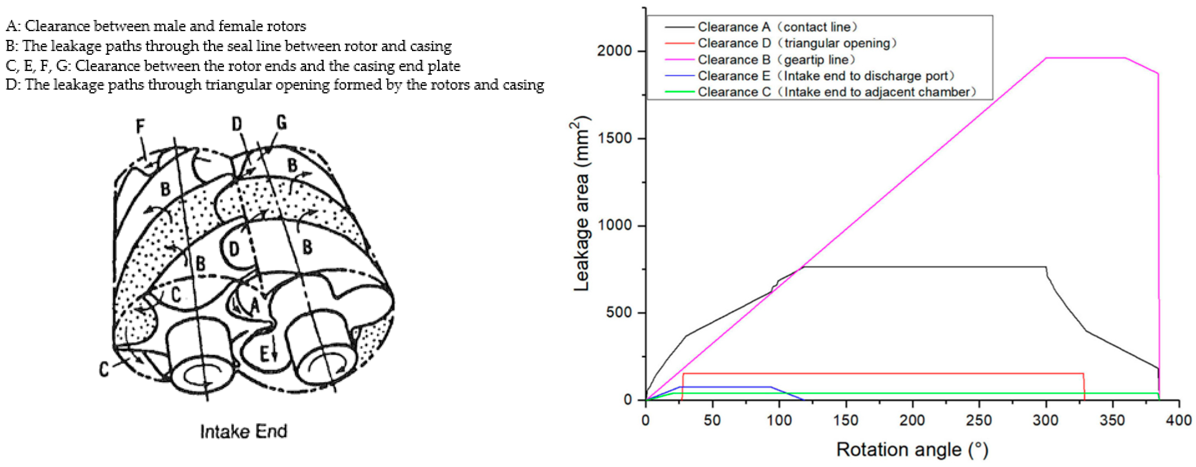
  • Losses in the rotor, working chamber, and blade-free space of positive displacement machines operating in two-phase conditions are primarily due to mechanical friction, internal leaks, and mismatched expansion ratios caused by a constant volume ratio. Research indicates that these inefficiencies are particularly significant in screw, piston and scroll expanders, where variable two-phase flow conditions exacerbate losses associated with leakage and friction. In addition, non-equilibrium phase transition processes contribute to irreversible thermodynamic losses, especially during rapid expansion phases. To address these challenges, strategies have been proposed that include optimizing the geometry of the rotor and working chamber, using advanced seals, adaptive speed control, and implementing multi-stage expansion systems that are better suited to operating conditions. It is also important to introduce real-time monitoring systems and continue research on phase transition control, which is key to increasing the efficiency and reliability of positive displacement machines in energy recovery and renewable energy applications.
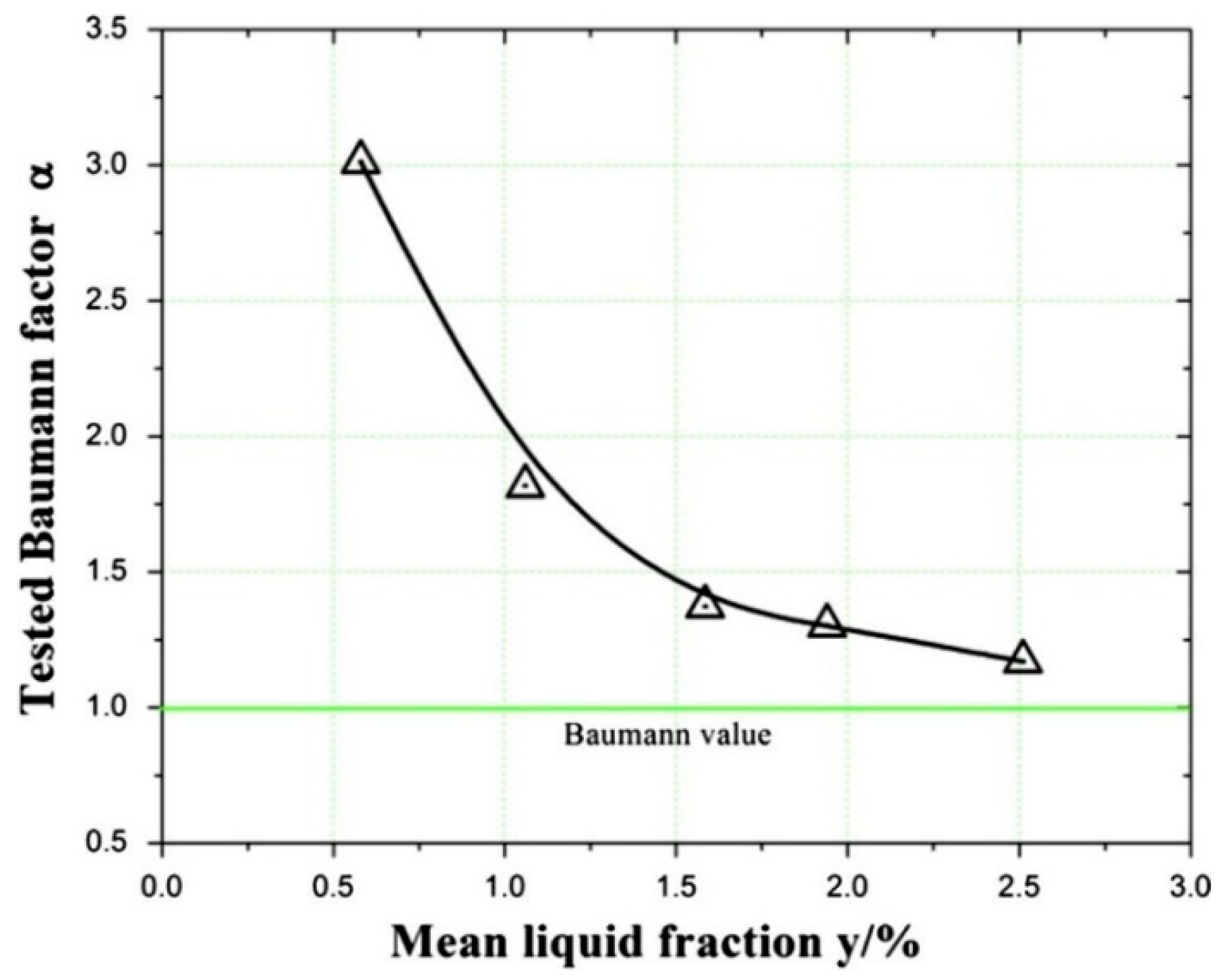
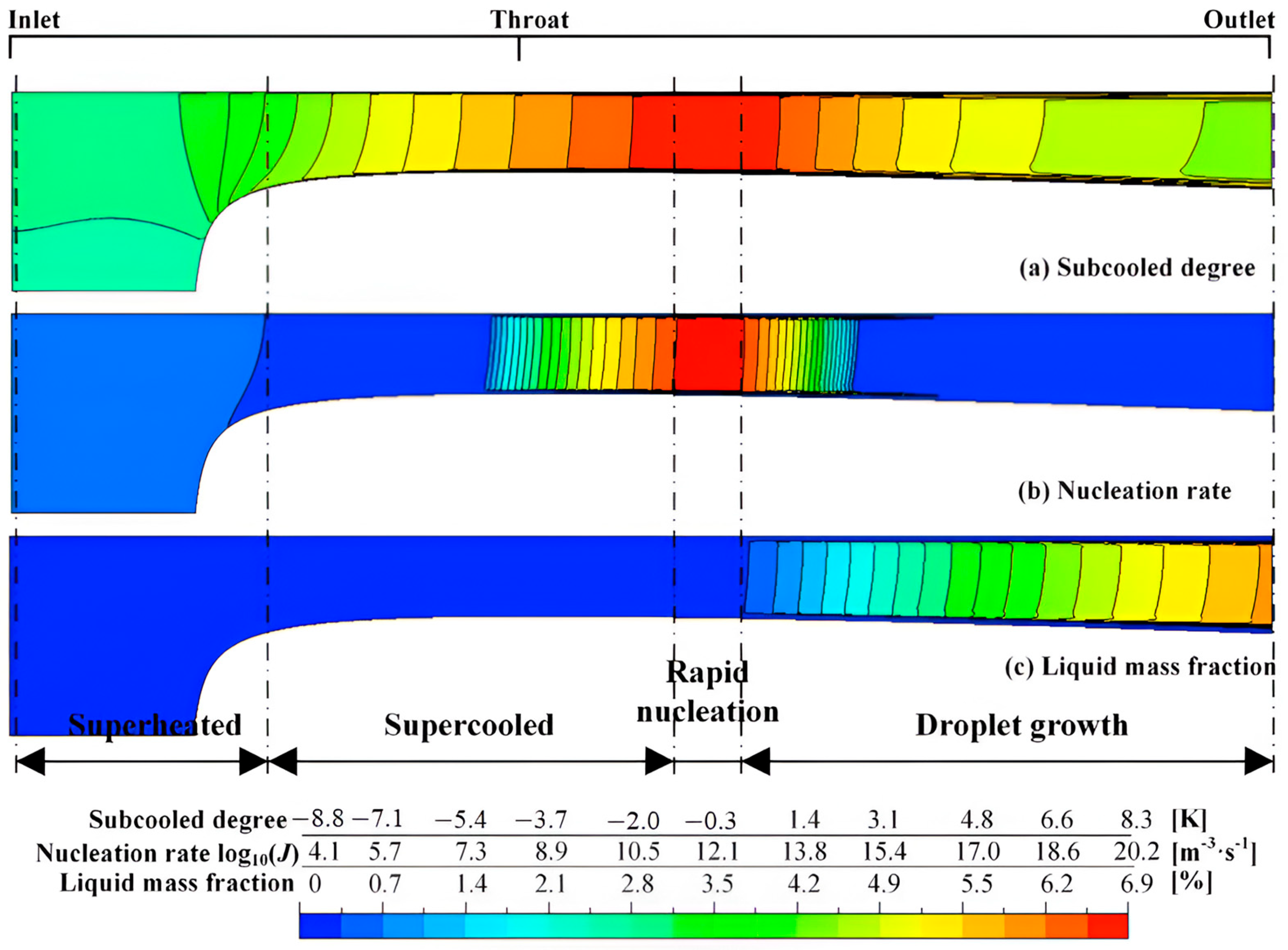
  • Losses due to wetness in two-phase expansion arise from complex thermodynamic, fluid dynamic, and geometrical design, with key factors including interfacial friction, slip ratios, and nucleation dynamics. Homogeneous nucleation in supercooled vapor causes abrupt condensation shocks, which lead to significant entropy spikes and energy dissipation. Geometrical aspects like blade design, for example, and flow-path steepness affect condensation timing and intensity, while operational conditions such as low liquid fractions amplify losses, especially in cryogenic expanders. Mitigation strategies include promoting heterogeneous nucleation through impurities or droplets, optimizing the design of the expander, and adjusting inlet conditions to delay nucleation.

Author Contributions

Writing—original draft preparation, writing—review and editing, and investigation, M.S.; writing—original draft preparation, writing—review and editing, and investigation, S.L.; writing—original draft preparation, writing—review and editing, conceptualization, visualization, methodology, investigation, and supervision, S.D.; writing—review and editing, and supervision, P.K. All authors have read and agreed to the published version of the manuscript.

Funding

This research was funded by the National Science Centre (NCN), Poland, grant number 2024/53/N/ST8/02547 within PRELUDIUM-23. Part of this study was supported by the Foundation for Polish Science (FNP) through START 2024 program.

Acknowledgments

The authors would like to thank Wrocław University of Science and Technology, Poland, and Institut Teknologi Sumatera, Indonesia, for the collaboration in this research.

Conflicts of Interest

The authors declare no conflicts of interest.

Nomenclature

The following symbols and abbreviations are used in this manuscript:
At/AmixArea ratio between the nozzle throat and the mixing section
ABaumann factor
CcCondensation coefficient
CeEvaporation coefficient
SEntropy generation or entropy loss
d0Orifice diameter
LLength
poutOutlet pressure
pinInlet pressure
TinInlet temperature
ϕmEntrainment ratio (ratio of secondary to primary mass flow)
xVapor quality
yWetness
y+Near-wall region
CFDComputational fluid dynamics
CNTClassical nucleation theory
COPCoefficient of performance
OFCOrganic flash cycle
ORCOrganic Rankine cycle
HEMHomogeneous equilibrium model
NDANozzle diverging angles
NXPNozzle exit position
MUSCLMonotonic upstream-centered scheme for conservation laws
PLRPressure lifting ratio
PRISMAPreferred Reporting Items for Systematic Reviews and Meta-Analyses
RANSReynolds-averaged Navier–Stokes
RNGRe-normalization group
UDFUser-defined functions
USDUser-defined scalars
WoSWeb of Science

References

  1. Van Heule, X.; Skiadopoulos, A.; Manolakos, D.; De Paepe, M.; Lecompte, S. Modelling of Two-Phase Expansion in a Reciprocating Expander. Appl. Therm. Eng. 2023, 218, 119224. [Google Scholar] [CrossRef]
  2. Francesconi, M.; Briola, S.; Antonelli, M. A Review on Two-Phase Volumetric Expanders and Their Applications. Appl. Sci. 2022, 12, 10328. [Google Scholar] [CrossRef]
  3. Bellos, E. A Review of Organic Rankine Cycles with Partial Evaporation and Dual-Phase Expansion. Sustain. Energy Technol. Assess. 2024, 72, 104059. [Google Scholar] [CrossRef]
  4. Ottaviano, S.; Poletto, C.; Ancona, M.A.; Melino, F. Experimental Investigation on Micro-ORC System Operating with Partial Evaporation and Two–Phase Expansion. Energy Convers. Manag. 2022, 274, 116415. [Google Scholar] [CrossRef]
  5. Fischer, J. Comparison of Trilateral Cycles and Organic Rankine Cycles. Energy 2011, 36, 6208–6219. [Google Scholar] [CrossRef]
  6. Wang, Q.; Wu, W.; Li, D.; Wang, J.; He, Z. Thermodynamic Analysis and Optimization of Four Organic Flash Cycle Systems for Waste Heat Recovery. Energy Convers. Manag. 2020, 221, 113171. [Google Scholar] [CrossRef]
  7. Badr, O.; O’Callaghan, P.W.; Hussein, M.; Probert, S.D. Multi-Vane Expanders as Prime Movers for Low-Grade Energy Organic Rankine-Cycle Engines. Appl. Energy 1984, 16, 129–146. [Google Scholar] [CrossRef]
  8. Imran, M.; Usman, M.; Park, B.-S.; Lee, D.-H. Volumetric Expanders for Low Grade Heat and Waste Heat Recovery Applications. Renew. Sustain. Energy Rev. 2016, 57, 1090–1109. [Google Scholar] [CrossRef]
  9. Elbel, S.; Hrnjak, P. Experimental Validation of a Prototype Ejector Designed to Reduce Throttling Losses Encountered in Transcritical R744 System Operation. Int. J. Refrig. 2008, 31, 411–422. [Google Scholar] [CrossRef]
  10. Li, Y.; Deng, J. Numerical Investigation on the Performance of Transcritical CO2 Two-Phase Ejector with a Novel Non-Equilibrium CFD Model. Energy 2022, 238, 121995. [Google Scholar] [CrossRef]
  11. Sun, W.; Niu, L.; Chen, S.; Sun, X.; Hou, Y. Numerical Investigation of Nitrogen Spontaneous Condensation Flow in Cryogenic Nozzles Using Varying Nucleation Theories. Cryogenics 2015, 68, 19–29. [Google Scholar] [CrossRef]
  12. Smith, I.K. Review of the Development of Two-Phase Screw Expanders. In Proceedings of the IMECHE Conference Transactions, Brighton, UK, 13–15 September 1999; Mechanical Engineering Publications: New York, NY, USA, 1999; Volume 6, pp. 95–104. [Google Scholar]
  13. Daniarta, S.; Kolasiński, P. A Preliminary Study of Two-Phase Volumetric Expanders and Their Application in ORC Systems. In Proceedings of the 6th International Seminar on ORC Power Systems, Munich, Germany, 11–13 October 2021; Wieland, C., Karellas, S., Quoilin, S., Schifflechner, C., Dawo, F., Spliethoff, H., Eds.; Technical University of Munich: Munich, Germany, 2021. [Google Scholar]
  14. Page, M.J.; McKenzie, J.E.; Bossuyt, P.M.; Boutron, I.; Hoffmann, T.C.; Mulrow, C.D.; Shamseer, L.; Tetzlaff, J.M.; Akl, E.A.; Brennan, S.E.; et al. The PRISMA 2020 Statement: An Updated Guideline for Reporting Systematic Reviews. BMJ 2021, 372, n71. [Google Scholar] [CrossRef] [PubMed]
  15. Van Eck, N.; Waltman, L. Software Survey: VOSviewer, a Computer Program for Bibliometric Mapping. Scientometrics 2009, 84, 523–538. [Google Scholar] [CrossRef] [PubMed]
  16. Kermani, M.J.; Gerber, A.G. A General Formula for the Evaluation of Thermodynamic and Aerodynamic Losses in Nucleating Steam Flow. Int. J. Heat Mass Transf. 2003, 46, 3265–3278. [Google Scholar] [CrossRef]
  17. Bakhtar, F.; White, A.J.; Mashmoushy, H. Theoretical Treatments of Two-Dimensional Two-Phase Flows of Steam and Comparison with Cascade Measurements. Proc. Inst. Mech. Eng. Part C 2005, 219, 1335–1355. [Google Scholar] [CrossRef]
  18. Bakhtar, F.; Zamri, M.Y. On the Performance of a Cascade of Improved Turbine Nozzle Blades in Nucleating Steam—Part 3: Theoretical Analysis. Proc. Inst. Mech. Eng. Part C 2011, 225, 1649–1671. [Google Scholar] [CrossRef]
  19. Mahpeykar, M.R.; Lakzian, E.; Amirirad, E. Reduction of Thermodynamic Losses in a Supersonic Nucleating Steam Nozzle by Spraying Water Droplets. Sci. Iran. 2009, 16, 253–262. [Google Scholar]
  20. Mahpeykar, M.R.; Amirirad, E.; Lakzian, E. The Effects of Water Injections in Wet Steam Flow in Different Regions of a Mini Laval Nozzle. In Proceedings of the International Conference on Nanochannels, Microchannels, and Minichannels, Darmstadt, Germany, 23–25 June 2008; pp. 355–361. [Google Scholar]
  21. Takeuchi, H.; Nishijima, H.; Ikemoto, T. World’s First High Efficiency Refrigeration Cycle with Two-Phase Ejector: “EJECTOR CYCLE”; Denso Corporation: Kariya, Japan, 2004. [Google Scholar]
  22. Bulinski, Z.; Smolka, J.; Fic, A.; Banasiak, K.; Nowak, A.J. A Comparison of Heterogenous and Homogenous Models of Two-Phase Transonic Compressible CO2 Flow through a Heat Pump Ejector. IOP Conf. Ser. Mater. Sci. Eng. 2010, 10, 12019. [Google Scholar] [CrossRef]
  23. Lawrence, N.; Elbel, S. Experimental and Analytical Investigation of Two-Phase Ejector Air-Conditioning Cycles Using Low-Pressure Refrigerants R134a and R1234yf; SAE Technical Paper 2013-01-1495; SAE International: Warrendale, PA, USA, 2013. [Google Scholar] [CrossRef]
  24. Liu, Y.; Yu, J. Performance Analysis of an Advanced Ejector-Expansion Autocascade Refrigeration Cycle. Energy 2018, 165, 859–867. [Google Scholar] [CrossRef]
  25. Yazdani, M.; Alahyari, A.A.; Radcliff, T.D. Numerical Modeling and Validation of Supersonic Two-Phase Flow of CO2 in Converging-Diverging Nozzles. J. Fluids Eng. 2013, 136, 014503. [Google Scholar] [CrossRef]
  26. Zhu, J.; Elbel, S. A New Control Mechanism for Two-Phase Ejector in Vapor Compression Cycles for Automotive Applications Using Adjustable Motive Nozzle Inlet Swirl. SAE Int. J. Passeng. Cars-Mech. Syst. 2016, 9, 44–51. [Google Scholar] [CrossRef]
  27. Bilir Sag, N.; Ersoy, H.K. Experimental Investigation on Motive Nozzle Throat Diameter for an Ejector Expansion Refrigeration System. Energy Convers. Manag. 2016, 124, 1–12. [Google Scholar] [CrossRef]
  28. Jeon, Y.; Kim, S.; Kim, D.; Chung, H.J.; Kim, Y. Performance Characteristics of an R600a Household Refrigeration Cycle with a Modified Two-Phase Ejector for Various Ejector Geometries and Operating Conditions. Appl. Energy 2017, 205, 1059–1067. [Google Scholar] [CrossRef]
  29. Baek, S.; Ko, S.; Song, S.; Ryu, S. Numerical Study of High-Speed Two-Phase Ejector Performance with R134a Refrigerant. Int. J. Heat Mass Transf. 2018, 126, 1071–1082. [Google Scholar] [CrossRef]
  30. Wen, C.; Gong, L.; Ding, H.; Yang, Y. Steam Ejector Performance Considering Phase Transition for Multi-Effect Distillation with Thermal Vapour Compression (MED-TVC) Desalination System. Appl. Energy 2020, 279, 115831. [Google Scholar] [CrossRef]
  31. Atmaca, A.U.; Erek, A.; Ekren, O. One-Dimensional Analysis of the Convergent-Divergent Motive Nozzle for the Two-Phase Ejector: Effect of the Operating and Design Parameters. Appl. Therm. Eng. 2020, 181, 115866. [Google Scholar] [CrossRef]
  32. Zheng, L.; Wang, L.; Deng, J. An Investigation on the Irreversibility in the CO2 Two-Phase Ejector Based on the One-Dimensional Distribution Model. Int. J. Therm. Sci. 2022, 182, 107839. [Google Scholar] [CrossRef]
  33. Oberti, R.; Metsue, A.; Fang, Y.; Poncet, S. Numerical Simulations and Local Entropy Generation in a Two-Phase Transcritical Carbon Dioxide Ranque-Hilsch Vortex Tube. Int. J. Heat Mass Transf. 2024, 226, 125461. [Google Scholar] [CrossRef]
  34. Hosseini, S.A.; Aghdasi, M.R.; Lakzian, E.; Kim, H.D. Multi-Objective Optimization of the Effects of Superheat Degree and Blade Pitch on the Wet Steam Parameters. Int. J. Heat Mass Transf. 2023, 213, 124337. [Google Scholar] [CrossRef]
  35. Zhang, G.; Yang, Y.; Zhang, X.; Zhang, Z.; Chen, J.; Jin, Z.; Dykas, S. Nanoparticles-Induced Heterogeneous Condensation and Geometry Optimizations to Enhance Liquefaction Efficiency and Mitigate Exergy Loss in a Novel Hydrogen Liquefaction Two-Phase Expander. Energy 2024, 313, 134006. [Google Scholar] [CrossRef]
  36. Ding, H.; Dong, Y.; Yang, Y.; Wen, C. Performance and Energy Utilization Analysis of Transcritical CO2 Two-Phase Ejector Considering Non-Equilibrium Phase Changes. Appl. Energy 2024, 372, 123810. [Google Scholar] [CrossRef]
  37. Chandran, R.J.; Arumugam, S.K.; Sadasivan, S.; Kanna, P.R.; Chen, F. Two-Phase Simulation of Transcritical CO2 flow in Nozzle and Ejector Using the Homogeneous Equilibrium Model. J. Therm. Anal. Calorim. 2024, 149, 5367–5380. [Google Scholar] [CrossRef]
  38. Lemmon, E.W.; Bell, I.H.; Huber, M.L.; McLinden, M.O. NIST Standard Reference Database 23: Reference Fluid Thermodynamic and Transport Properties-REFPROP, Version 10.0; National Institute of Standards and Technology: Gaithersburg, MD, USA; Standard Reference Data Program: Gaithersburg, MD, USA, 2018; pp. 45–46. [Google Scholar]
  39. Kumar, A.; Parisi, S.; Agromayor, R.; Walther, J.H.; Haglind, F. Numerical Analysis of a Two-Phase Turbine: A Comparative Study Between Barotropic and Mixture Models. J. Eng. Gas Turbines Power 2024, 147, 051013. [Google Scholar] [CrossRef]
  40. Taniguchi, H.; Kudo, K.; Giedt, W.H.; Park, I.; Kumazawa, S. Analytical and Experimental Investigation of Two-Phase Flow Screw Expanders for Power Generation. J. Eng. Gas Turbines Power 1988, 110, 628–635. [Google Scholar] [CrossRef]
  41. Mahmoud, A.M.; Sherif, S.A.; Lear, W.E. Frictional and Internal Leakage Losses in Rotary-Vane Two-Phase Refrigerating Expanders. J. Energy Resour. Technol. 2010, 132, 021007. [Google Scholar] [CrossRef]
  42. Iodice, P.; Langella, G.; Amoresano, A. Energy Performance and Numerical Optimization of a Screw Expander–Based Solar Thermal Electricity System in a Wide Range of Fluctuating Operating Conditions. Int. J. Energy Res. 2020, 44, 1858–1874. [Google Scholar] [CrossRef]
  43. Wang, Q.; Huang, H.; Xu, L.; Yang, X.; He, Z.; Wu, W. Analysis of the Thermodynamic Disequilibrium Loss of the Two-Phase Expansion Process and Its Influence on the Performance of a Reciprocating Expander. IOP Conf. Ser. Mater. Sci. Eng. 2019, 604, 12041. [Google Scholar] [CrossRef]
  44. Weitzer, M.; Müller, D.; Karl, J. Two-Phase Expansion Processes in Heat Pump—ORC Systems (Carnot Batteries) with Volumetric Machines for Enhanced off-Design Efficiency. Renew. Energy 2022, 199, 720–732. [Google Scholar] [CrossRef]
  45. Kanno, H.; Shikazono, N. Experimental Study on Two-Phase Adiabatic Expansion in a Reciprocating Expander with Intake and Exhaust Processes. Int. J. Heat Mass Transf. 2016, 102, 1004–1011. [Google Scholar] [CrossRef]
  46. Tian, Y.; Xing, Z.; He, Z.; Wu, H. Modeling and Performance Analysis of Twin-Screw Steam Expander Under Fluctuating Operating Conditions in Steam Pipeline Pressure Energy Recovery Applications. Energy 2017, 141, 692–701. [Google Scholar] [CrossRef]
  47. Carlos Mendoza, L.; Lemofouet, S.; Schiffmann, J. Two-Phase and Oil-Free Co-Rotating Scroll Compressor/Expander. Appl. Therm. Eng. 2019, 148, 173–187. [Google Scholar] [CrossRef]
  48. Aghagoli, A.; Sorin, M. CFD Modelling and Exergy Analysis of a Heat Pump Cycle with Tesla Turbine Using CO2 as a Working Fluid. Appl. Therm. Eng. 2020, 178, 115587. [Google Scholar] [CrossRef]
  49. Jeon, Y.; Lee, D.; Cho, H. Optimization of Motive Nozzle Position in a Modified Two-Phase Ejector Expansion Household Refrigeration Cycle Using an Artificial Neural Network. Energy Rep. 2022, 8, 1114–1123. [Google Scholar] [CrossRef]
  50. Ma, Y.; Zhou, Y.; Zhu, Z. The Investigation of Two-Phase Expansion Performance with Indicator Diagram in a Twin-Screw Expander. Processes 2023, 11, 1862. [Google Scholar] [CrossRef]
  51. Anisimova, M.P.; Stekol’shchikov, E.V. Energy Losses in a Two-Phase Flow Due to Mechanical Interaction of the Phases. J. Eng. Phys. 1968, 15, 810–815. [Google Scholar] [CrossRef]
  52. Motamed-Amini, A.; Owen, I. The Expansion of Wet Steam through a Compressible Confined Vortex in a Fluidic Vortex Diode. Int. J. Multiph. Flow 1987, 13, 845–856. [Google Scholar] [CrossRef]
  53. Bohn, D.E.; Sürken, N.; Kreitmeier, F. Nucleation Phenomena in a Multi-Stage Low Pressure Steam Turbine. Proc. Inst. Mech. Eng. Part A 2003, 217, 453–460. [Google Scholar] [CrossRef]
  54. Bakhtar, F.; Henson, R.J.K.; Mashmoushy, H. On the Performance of a Cascade of Turbine Rotor Tip Section Blading in Wet Steam. Part 5: Theoretical Treatment. Proc. Inst. Mech. Eng. Part C 2006, 220, 457–472. [Google Scholar] [CrossRef]
  55. Teymourtash, A.R.; Esfahani, J.A.; Mousavi Shaegh, S.A. The Effects of Rate of Expansion and Injection of Water Droplets on the Entropy Generation of Nucleating Steam Flow in a Laval Nozzle. Heat Mass Transf. 2009, 45, 1185–1198. [Google Scholar] [CrossRef]
  56. Niu, L.; Hou, Y.; Sun, W.; Chen, S. The Measurement of Thermodynamic Performance in Cryogenic Two-Phase Turbo-Expander. Cryogenics 2015, 70, 76–84. [Google Scholar] [CrossRef]
  57. Sun, W.; Chen, S.; Niu, L.; Hou, Y. Wetness Loss Prediction for a Wet-Type Cryogenic Turbo-Expander Based on 3-D Numerical Simulation. Appl. Therm. Eng. 2015, 91, 1032–1039. [Google Scholar] [CrossRef]
  58. Sun, W.; Chen, S.; Hou, Y.; Bu, S.; Ma, Z.; Zhang, L.; Pan, L. Numerical Studies on Two-Phase Flow in Cryogenic Radial-Inflow Turbo-Expander Using Varying Condensation Models. Appl. Therm. Eng. 2019, 156, 168–177. [Google Scholar] [CrossRef]
  59. Niu, L.; Zhong, Z.; Hong, X.; Chen, S.; Hou, Y. Numerical Study on Two-Phase Expansion Performance and Quantitative Analysis of Wetness Loss in Cryogenic Turbo-Expander. Cryogenics 2020, 110, 103123. [Google Scholar] [CrossRef]
  60. Sun, W.; Chen, S.; Hou, Y.; Bu, S.; Ma, Z.; Zhang, L. Numerical Studies of Nitrogen Spontaneous Condensation Flow in Laval Nozzles Using Varying Droplet Growth Models. Int. J. Multiph. Flow 2019, 121, 103118. [Google Scholar] [CrossRef]
  61. Chen, S.; Sun, W.; Niu, L.; Chen, L.; Hou, Y. Effect of Impeller Blade Profile on the Cryogenic Two-Phase Turbo-Expander Performance. Appl. Therm. Eng. 2017, 126, 884–891. [Google Scholar] [CrossRef]
  62. Yang, Y.; Peng, H.; Wen, C. A Novel Dehumidification Strategy to Reduce Liquid Fraction and Condensation Loss in Steam Turbines. Entropy 2021, 23, 1225. [Google Scholar] [CrossRef]
  63. Hu, P.; Zhao, P.; Li, Q.; Hou, T.; Wang, S.; Cao, L.; Wang, Y. Performance of Non-Equilibrium Condensation Flow in Wet Steam Zone of Steam Turbine Based on Modified Model. Energy 2023, 267, 126571. [Google Scholar] [CrossRef]
  64. Witlox, H.; Harper, M.; Bowen, P.; Cleary, V. Flashing Liquid Jets and Two-Phase Droplet Dispersion: II. Comparison and Validation of Droplet Size and Rainout Formulations. J. Hazard. Mater. 2007, 142, 797–809. [Google Scholar] [CrossRef]
  65. Lee, M.S.; Lee, H.; Hwang, Y.; Radermacher, R.; Jeong, H.-M. Optimization of Two-Phase R600a Ejector Geometries Using a Non-Equilibrium CFD Model. Appl. Therm. Eng. 2016, 109, 272–282. [Google Scholar] [CrossRef]
  66. Weres, O. Integrated Studies of Electrophysical Processes in Steam Turbines. J. Mech. Eng. 2023, 26, 33–41. [Google Scholar]
  67. Tarelin, A.O.; Annopolska, I.Y. Wet Steam Flow Ionization and Prospects to Practically Apply Electrical Discharge Devices in Turbo Installation. J. Mech. Eng. 2019, 22, 4–13. [Google Scholar] [CrossRef]
Figure 1. A flowchart of systematic methodology.
Energies 18 03504 g001
Figure 2. Thematic clustering of keywords based on co-occurrence analysis.
Energies 18 03504 g002
Figure 3. Effect of nozzle throat diameter on the entrainment ratio (ϕm), reproduced with permission from [23].
Energies 18 03504 g003
Figure 4. Contour of phase transition rate and its profile for the novel geometry ejector, reproduced with permission from [29]. In this figure, positive and negative values indicate evaporation and condensation rates, respectively.
Energies 18 03504 g004
Figure 5. The simulation results of (a) mean static pressure in and around the suction chamber with different diverging nozzle lengths and (b) streamlining the contour of the mean static pressure with different nozzle exit locations [29].
Energies 18 03504 g005
Figure 6. Profile of mean static pressure along the centerline inside the suction channel with different nozzle exit locations, reproduced with permission from [29].
Energies 18 03504 g006
Figure 7. Steam ejector’s flow structure for (a) high underexpanded flows, (b) slight underexpanded flows, and (c) overexpanded flows, reproduced with permission from [30].
Energies 18 03504 g007
Figure 8. Effect of the suction chamber pressure nozzles on (a) ϕm and (b) entropy loss [30].
Energies 18 03504 g008
Figure 9. Illustration (cut-away view) of the modular prototype ejector with integrated needle, reproduced with permission from [9].
Energies 18 03504 g009
Figure 10. Variation in leakage to the expander cavity from the rotor slot (modified intake) through the gap between the face of the vanes and the rotor slot [41].
Energies 18 03504 g010
Figure 11. Variation in the ideal and actual mass flow rates through the expander as a function of rotational speed, reproduced with permission from [41].
Energies 18 03504 g011
Figure 12. Variations in screw expander efficiency with evaporation temperature in the condensation pressure range between 0.1 and 1 bar, reproduced with permission from [42].
Energies 18 03504 g012
Figure 13. Leakage areas and leakage paths in a two-phase screw expander, reproduced with permission from [40,50].
Energies 18 03504 g013
Figure 14. The illustration of a vortex diode, reproduced with permission from [52].
Energies 18 03504 g014
Figure 15. The experimental (indicated by triangle symbol) vs. theoretical Baumann factor based on the study from Niu et al., reproduced with permission from [56].
Energies 18 03504 g015
Figure 16. The Baumann factor from a study by Sun et al., reproduced with permission from [57].
Energies 18 03504 g016
Figure 17. The observed distribution of (a) supercooling, (b) nucleation rate, and (c) liquid mass fraction based on the simulation study, reproduced with permission from [60].
Energies 18 03504 g017
Figure 18. The result of the predicted relative breakdown of losses associated with efficiency, reproduced with permission from [59].
Energies 18 03504 g018
Disclaimer/Publisher’s Note: The statements, opinions and data contained in all publications are solely those of the individual author(s) and contributor(s) and not of MDPI and/or the editor(s). MDPI and/or the editor(s) disclaim responsibility for any injury to people or property resulting from any ideas, methods, instructions or products referred to in the content.

