Abstract
Drilling oil and gas wells is a complex process that requires a combination of several parameters to dig into the ground. Inappropriate drilling parameter settings and reaction forces can lead to unwanted vibrations, which can negatively impact the drill string and cause damage to drill bits. To reduce unwanted oscillations, drilling vibration modeling is the first approach used to determine the behavior of the drill string under various conditions. Natural frequencies, one of the modal characteristics of a vibrating drill string, can be estimated by analytical or numerical models. However, as the field conditions become more complicated, analytical models become increasingly difficult to use, and alternative approaches must be adopted. The main objective of this paper is to investigate the natural frequencies of drill strings with real geometry under coupled vibration modes using both analytical and finite element methods. This study bridges the literature gap in modeling stepped drill string geometries, which are usually represented as uniform beams. This paper used analytical and finite element models to determine the drill string’s lateral, axial, and torsional natural frequencies under varying lengths of drill pipes and drill collars. To assess the reliability of finite element models under complex geometry, the drill string was approximated as a stepped beam rather than a uniform beam. Then, a comparison was made with analytical models. The results showed that the length of drill pipes has a pronounced effect on the natural frequencies of the overall drill string for the three vibrational modes, while drill collar length only has a notable impact on the torsional mode. These findings contribute to drilling systems’ reliability and efficiency in the oil and gas energy sector.
1. Introduction
Oil and gas are fossil fuels located thousands of meters underground. To reach the hydrocarbon reservoir and extract its content, a well must be drilled and linked to the reservoir from surface. For this, and under the combined action of a sufficient axial load and adequate rotation, the drill bit crushes the rocks and penetrates the geological formations. The rotation of the drill bit is provided by the top rotary system and is transmitted through the drill pipes. Meanwhile, very thick pipes, known as drill collars, supply the axial load.
To ensure the stability of the drill string, the transition from drill pipes to drill collars is progressively made by adding heavy-weight drill pipes [1]. The difference in dimensions between the components of the drill string divides it into two parts: one in tension (the upper part) and one in compression (the lower part) [2]. Complex loadings to which the drill string is subjected stimulate the apparition of harmful vibrations and other problems [3]. It has been found that drill string vibrations are the primary cause of drill string premature failure [4], inefficient rock cutting [5], and excessive drill bit wear and deformation [6]. Drill string vibrations can be classified into lateral, axial, and torsional. In each category, there may be a severe case that causes more damage than the simple mode. Bit whirl, bit bounce, and stick-slip are the extreme cases of lateral, axial, and torsional vibrations, respectively.
Drill string vibrations are most often self-excited [7], which means that the drill string is already ready to be excited, and any disturbance can cause it to vibrate in one of the mentioned modes or even in a coupled mode. Consequently, drilling operations are carried out in a predefined way, in which drilling parameters, such as depth and drilling phases, are recommended to avoid excitation regions of the drill string [8]. These undesired vibrations not only weaken mechanical integrity but also reduce energy efficiency by increasing non-productive time and top drive energy consumption during drilling. These issues make vibration analysis and mitigation a critical challenge for energy optimization and development.
Many researchers have been interested in modeling the vibrations of drill strings [9]. Lumped and continuous models have been developed and used to understand the factors responsible for the occurrence of vibrations [10,11]. Based on that, monitoring and active control of drilling vibrations have been performed [12,13]. Many studies have investigated the finite element models of drilling system, and the natural frequencies of the entire system have been calculated [14,15]. Most often, finite element models are flexible methods that can be easily implemented to estimate the natural frequencies of drill strings under complex conditions and geometries. However, there is always a need to assess the reliability of such models by performing comparisons with analytical models for further use under field conditions. Understanding and managing drill string dynamics align with broader research of reducing equipment failure rate in petroleum industry, optimizing energy consumption during drilling operations, and extending drilling tools life. These goals are essential for energy systems reliability and industrial energy efficiency.
Several finite elements and lumped parameter models have been developed for simulating drill string vibration, with a focus on axial, torsional, and lateral modes of vibration. Initial models, such as that by Khulief et al. (2007) in [16], employed complex dynamic couplings that included torsional-bending inertia and stick-slip forces but applied idealized boundary conditions and excluded the effects of drilling fluids and lateral vibrations, thereby limiting their real-world applicability. Subsequent studies (e.g., Germay and Detournay, 2009 in [7]; Ghasemloonia et al., 2013 in [14]) addressed some of the coupling terms but typically did not consider significant vibration modes with idealized contact and damping conditions. Then, Al Dushashi et al. (2018) in [15] evaluated the effect of assumptions in the model, such as beam theory selection, loading condition, and drill stem geometry, on drill string vibration predictions using finite element analysis with nonlinear properties. However, they did not envision coupling extreme cases of axial, torsional, and lateral drill string vibrations. De Moraes and Savi (2019) in [17] introduced a four-degree-of-freedom nonsmooth lumped-parameter model to represent coupled axial, torsional, and lateral drill string vibrations, incorporating bit–rock and wellbore interactions to simulate phenomena like bit-bounce, stick-slip, and whirling. The model neglected the effect of the drilling fluid and used a deterministic rock–bit interaction term.
In [18], Volpi et al. (2021) proposed a three-degree-of-freedom lumped-parameter model that encompasses coupled lateral–torsional vibrations in drill strings with nonlinear bit–rock interaction, fluid–structure dynamics, and stochastic uncertainty to generate probabilistic maps of zones of the severe regimes of critical vibration [19]. The model, however, considers constant angular velocity at the top drive and does not consider the high-frequency mode of vibrations. In [20], Meddah et al. (2025) investigated dynamic coupling interactions of coupled axial, torsional, and lateral vibrations in rotary drilling systems using field data acquired from measurement while drilling to assess high-frequency modes and their impact on drilling performance. This research did not, however, incorporate natural frequency analysis of the drill string under such coupled vibrations. Lastly, in [21], Guo et al. (2025) derived multiple nonlinear vibration models of the drill string by using the energy method and Lagrange equations to investigate the mechanism of increasing drilling speed. These models are validated only in ultra-high-pressure and high-temperature (ultra-HPHT) oil and gas wells.
The main limitations in previous studies on drill string dynamics often involve simplified geometries, typically idealizing the drill string as homogeneous beams or lumped masses. Additionally, these studies frequently suffer from partial coupling of axial, torsional, and lateral vibration modes, especially when estimating natural frequencies in stepped geometries. Approximations like constant top drive speed, idealized boundary conditions, and neglected drilling fluid effects further reduce their predictive accuracy under realistic drilling conditions.
Unlike previous work, this paper combines analytical and finite element models to explicitly estimate the natural frequencies of drill strings. We modeled the drill string as stepped beams to accurately capture real geometric transitions between drill pipes and collars. This approach enables a full-fledged analysis of coupled axial–torsional–lateral vibrations, as well as examining the modal characteristics’ influence of varied pipe and collar lengths. Our research, by considering stepped geometry and investigating the impact of variations in drill pipe and drill collar lengths on vibration properties, directly addresses the shortcomings of prior models. This comparative method highlights model reliability, enhancing accuracy and efficiency in vibration avoidance strategies for drilling systems, and eventually contributes to improved drilling system reliability and efficiency in the oil and gas sector.
The rest of this manuscript is organized as follows: In Section 2, a brief description of the drill string is provided to highlight its various components for the reader. In Section 3, the three types of vibrations and their modes are introduced for the drill string of a rotary drilling system. In Section 4, we describe the field data used in this study to design simulation scenarios that mimic field conditions. Section 5 is dedicated to developing a finite element model to analyze the natural frequencies of the drill string under the three vibrational modes, while Section 6 focuses on the analytical model used for the same purpose. Section 7 compares the reliability of the two models in estimating natural frequencies under lateral, axial, and torsional vibrations; this section also discusses the effect of drill string geometry (drill pipes and drill collars) on the characteristics of natural frequencies. Section 8 is dedicated to summarizing the limitations of this study and discussing possible improvements in the findings. Finally, the paper concludes with remarks and recommendations for future research.
2. Drill String of Rotary System
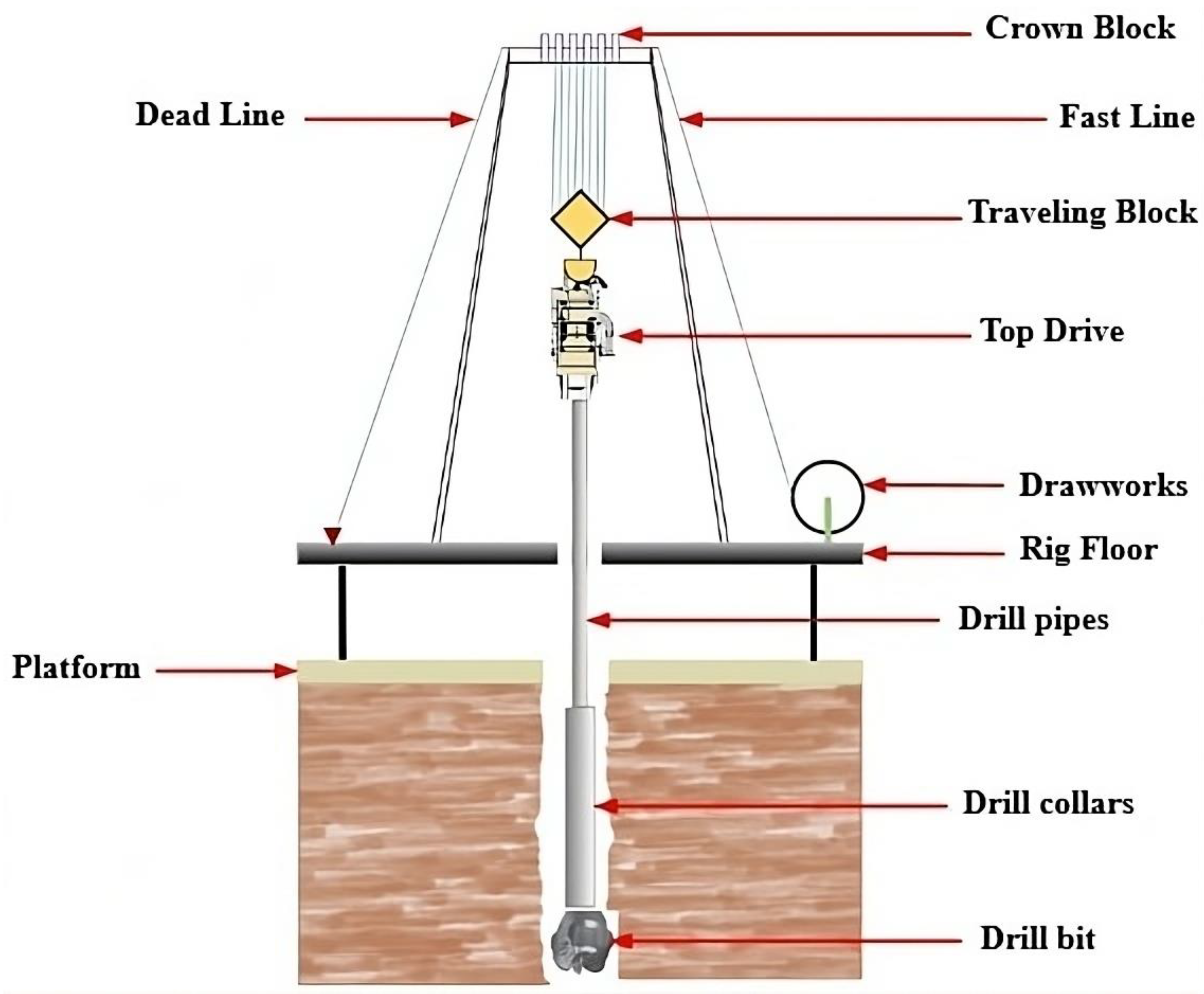
The rotary drilling method is based on the combination of three primary functions: applying weight on the bit, rotating the drill pipes, and circulating drilling fluid. Practically, the weight on the bit is provided by very heavy pipes with a larger diameter than that of regular pipes (Figure 1).
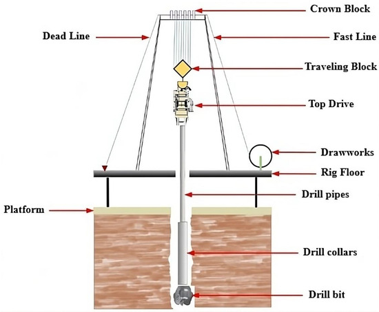
Figure 1.
Rotary drilling system typical schematic diagram.
These heavy pipes are located near the lower part of the drill string and form part of a component known as the bottom hole assembly (BHA), which is responsible for providing the necessary weight. Regarding the rotation of the drill pipes, previously, and around the 1980s and 1990s, all drilling rigs used a rotary table driven by an electric motor [22]. However, with advancements in the petroleum industry, a new rotation mechanism called the top drive appeared. As a result, most drilling rigs are currently equipped with both a top drive and a rotary table. Thus, rotation is transmitted from the rotation system to the heavy pipes and the bit through the drill pipes. In addition to weight and rotation, the circulation system uses high-pressure mud pumps to inject and return drilling fluid, which carries rock cuttings to the surface, cools the bit, maintains wellbore pressure, and provides geological information. Well control systems manage the formation fluid intrusion using blowout preventers and circulation methods [23]. Continuous monitoring of drilling parameters, such as weight on bit, depth, rotation speed, torque, pump pressure, and flow rate, is essential for safe and efficient drilling operations [8,21].
The drill string, or drill pipe assembly, is a set of pipes, heavy-weight pipes, and special components screwed together to form a continuous length of several kilometers (Figure 2).
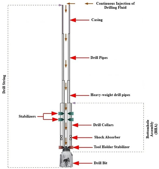
Figure 2.
Main components of the drill string assembly.
The drill string is the essential part of rotary drilling; its roles and functions enable it to connect the top drive system at the surface to the drill bit. Specifically, the drill string primarily fulfills the following tasks:
- Transmitting the rotational torque from the top drive to the drill bit;
- Suspending the drill bit;
- Serving as a circulation conduit for the drilling mud;
- Applying weight on the bit;
- Raising and lowering the drill bit.
Due to the slenderness of the pipes in the wellbore, effective control of the drill bit may not be achieved, which consequently leads to a series of problems such as vibrations [23].
3. Drill String Vibrations
Drill string vibrations are among the factors that make the drilling process costly and complex. From increasing drilling time to causing tool deformation, these vibrations create numerous problems and remain an obstacle to any attempt at optimizing drilling operations. In this regard, it is beneficial to analyze these vibrations and examine their triggering mechanisms, types, and different modeling techniques.
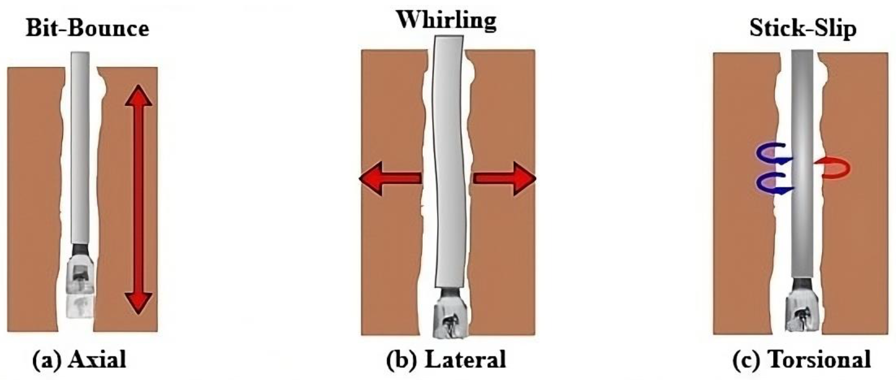
Based on observations made in the field, drill string vibrations do not manifest in the same form; in other words, they appear in three main modes: axial, lateral, and torsional (Figure 3).
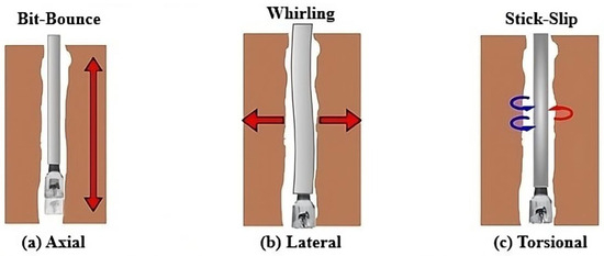
Figure 3.
Drill string vibrations: (a) axial, (b) lateral, and (c) torsional modes (red: clockwise direction, blue: counter clockwise direction).
Each vibration mode is caused by a triggering event. The axial mode is caused by the loss of contact between the bottom of the hole and the bit, which leads to the bit experiencing rebounds (bit bouncing), Figure 3a. The lateral mode is caused by the eccentric rotation of the drill string (whirling), Figure 3b. The final mode, which is the most damaging form of vibration, is governed by friction forces existing between the bit and the rock formation, Figure 3c. It has been observed that the appearance of one vibration mode can lead to the occurrence of other vibration modes, resulting in coupled vibration modes [11]. According to field observations, axial vibrations, once generated, tend to produce lateral vibrations, especially at the level of the BHA [1], while lateral vibrations in turn can cause axial and torsional vibrations [12]. Broadly speaking, three coupled vibration modes can occur during drilling: axial–lateral, lateral–torsional, and axial–torsional.
3.1. Axial Vibrations
Axial vibrations occur when the drill bit intermittently comes into contact with the bottom of the wellbore [13]; in other words, the bit loses contact with the formation and undergoes cyclic rebounds, which constitute the form in which axial vibrations arise [14]. Moreover, this vibration mode is strongly associated with the drilling of vertical wells, but other factors accelerate its occurrence, including the nonlinearity of the bit–rock interaction, the frequent use of roller cone bits (tricone), and drilling through hard formations [15]. The consequences of this vibration mode include
- Rapid wear of the drill bit;
- Deformation of cutting elements;
- Incorrect reading of weight on bit at the surface;
- Low rate of penetration;
- Difficulty in controlling the trajectory.
Generally, axial vibrations can be detected at the surface, which allows for necessary adjustments to be made to eliminate them.
3.2. Lateral Vibrations
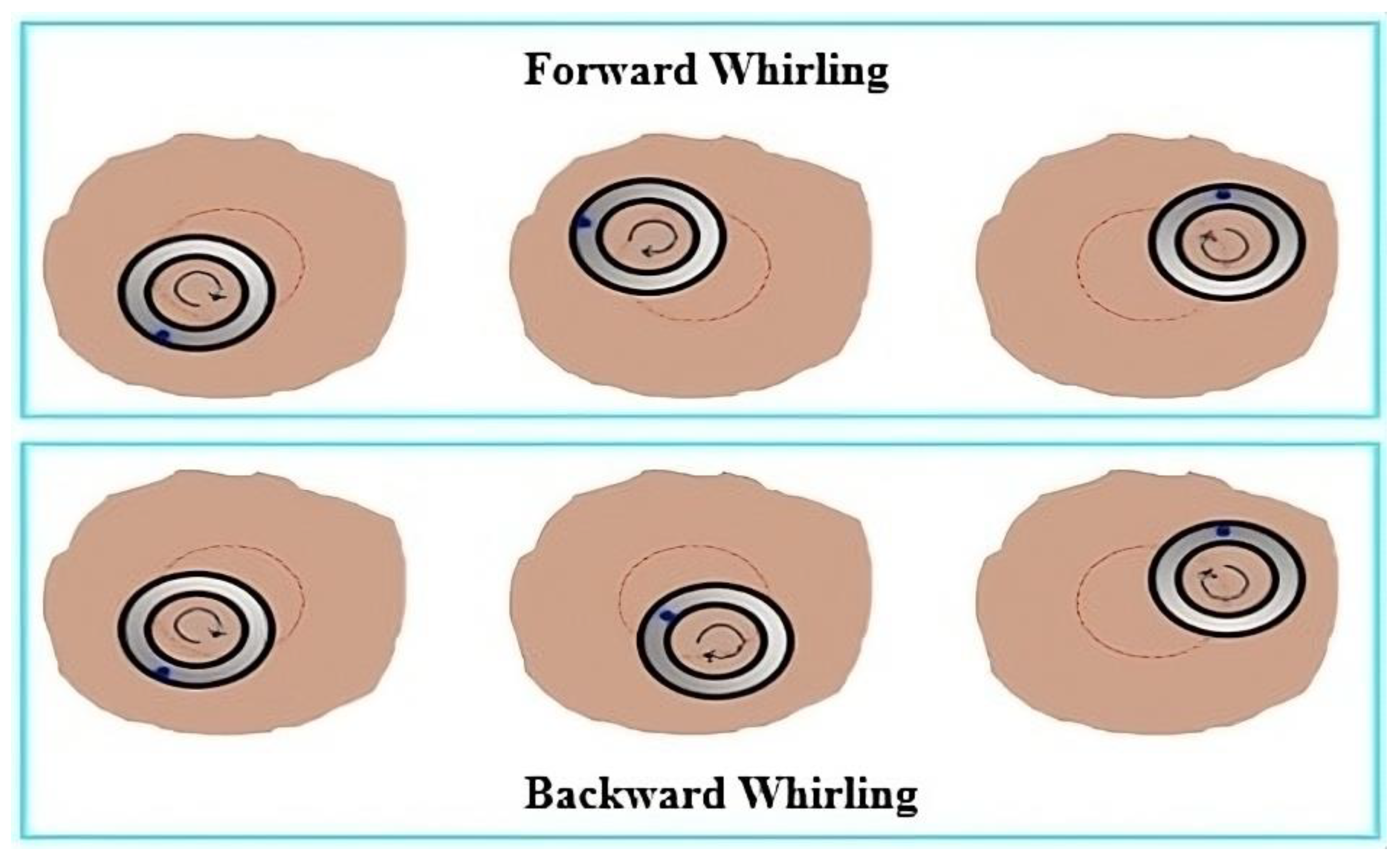
The rotation of the drill string, and more specifically the bottom hole assembly (BHA), involves interactions with the wellbore walls. As the frequency of these interactions increases, they escalate into very violent impacts, causing lateral oscillations [24]. Indeed, it has been acknowledged that these vibrations are responsible for numerous problems on drilling sites, primarily premature fatigue of BHA components and wear of stabilizers [25]. The severity of lateral vibrations lies in the fact that they generate lateral waves that are undetectable at the surface (waves that do not propagate) [16]. Additionally, these vibrations, through their lateral waves, can induce bending in the BHA [26]. The triggering factor of lateral vibrations is the center of gravity of the heavy-weight drill pipes [16]; if, at the initial moment, this center is slightly offset from the wellbore axis, its rotation creates a centrifugal force acting at the center of gravity, thereby accelerating lateral oscillations. Furthermore, as shown in Figure 4, two movements can accompany the occurrence of lateral vibrations [17]: forward whirling and backward whirling. Forward whirling occurs when the BHA, assumed to deviate from the wellbore axis, rotates in the same direction as the drill bit rotation [22]. The other movement occurs when the BHA rotates in the opposite direction to the drill bit rotation. Moreover, it is fair to say that all drilling tools directly influence the occurrence of lateral vibrations; for this reason, both PDC and roller cone bits can be subject to them [27]. At very high rotation speeds, and due to mass imbalances and forces created by the BHA and the bit–rock interaction, roller cone bits can vibrate laterally and exhibit whirling movements [28].
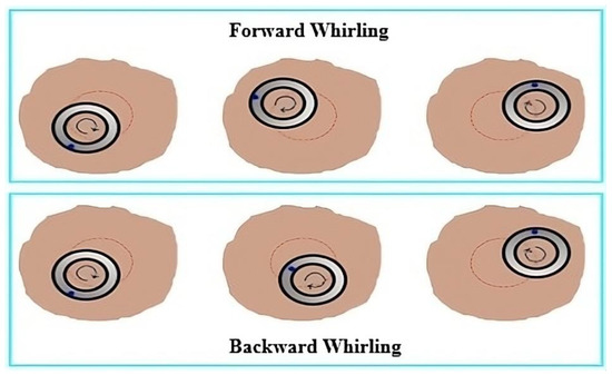
Figure 4.
The two movements accompanying lateral vibrations.
Similarly, under other conditions (high rotation speed and insufficient weight on bit), PDC bits can be vulnerable to lateral vibrations while exhibiting significant deformations [18].
3.3. Torsional Vibrations
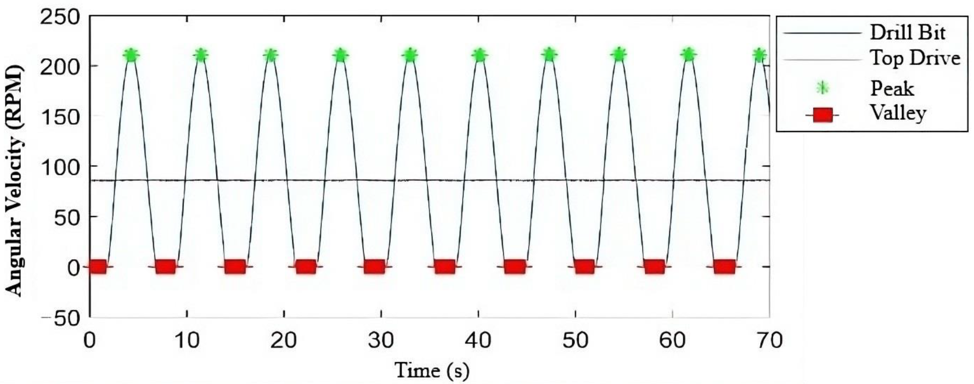
By comparing the rotation speed at the surface (the speed provided by the mechanism ensuring rotation) with that of the bit, it can be observed that the latter does not maintain a constant pattern, as shown in Figure 5. More precisely, its values fluctuate between zero and a value three times higher than the surface rotation speed [21,29], and this occurs over a specific period of time. Moreover, the irregular oscillations of the bit’s rotation speed represent the characteristic by which the stick-slip phenomenon, the most severe form of torsional vibrations, manifests itself [4].
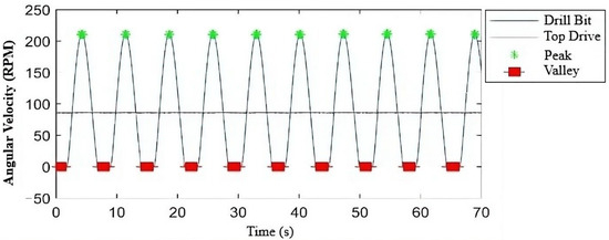
Figure 5.
Fluctuation of the tool’s rotation speed due to the occurrence of the stick-slip phenomenon.
Among other factors, these vibrations occur due to the rigidity of the drill string, which is highly excited during rotation. Of course, other factors also come into play and trigger the occurrence of torsional vibrations, primarily friction forces between the drill string and the wellbore walls [30], the highly nonlinear bit–rock interaction, and drilling through hard formations [31].
Based on analyses and data collected from sites where torsional vibrations have been observed, it was noted that the stick-slip phenomenon occurs cyclically during 50% of the total drilling time [20], illustrating why torsional vibrations, especially in their severe form (stick-slip), are classified among highly undesirable dynamics. The descending trend of the curve toward the valley, as shown in Figure 5, indicates that the bit enters the stick phase, which lasts for a certain period before suddenly releasing and entering the slip phase. This is indicated by the ascending trend of the curve toward the peak. These oscillations tend to repeat as long as the stick-slip phenomenon persists and remains present [32]. In summary, torsional vibrations and the stick-slip phenomenon are undesirable events that can cause significant damage and thus endanger drilling equipment. Moreover, in terms of impact on the petroleum industry, it has been proven that the stick-slip phenomenon is responsible for
- Irregular rotation of the bit at the bottom of the well;
- Significant reduction in the rate of penetration; given that nearly half of the drilling time exhibits torsional vibrations;
- The occurrence of other vibration modes; such as lateral mode; which can alter the dimensions of the well;
- Acceleration of fatigue failure in the drill string and various connections;
- Deformation and rapid wear of the bit;
- Manifestation of other problems such as wellbore instability and collapse.
Since these vibrations are the most destructive forms of vibrations, particular attention is given to their modeling in the field data analysis described in Section 4.
4. Field Data Analysis
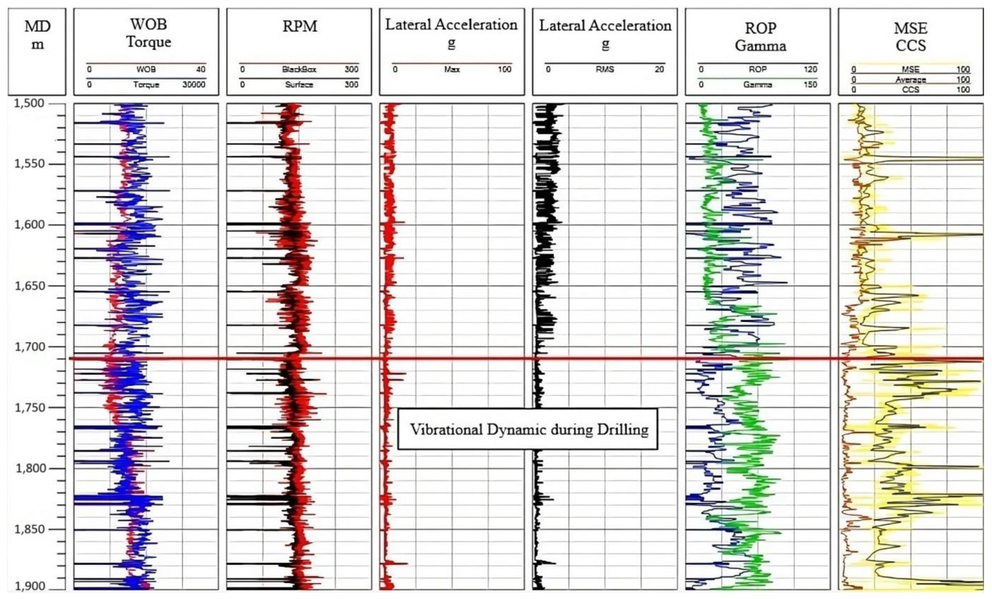
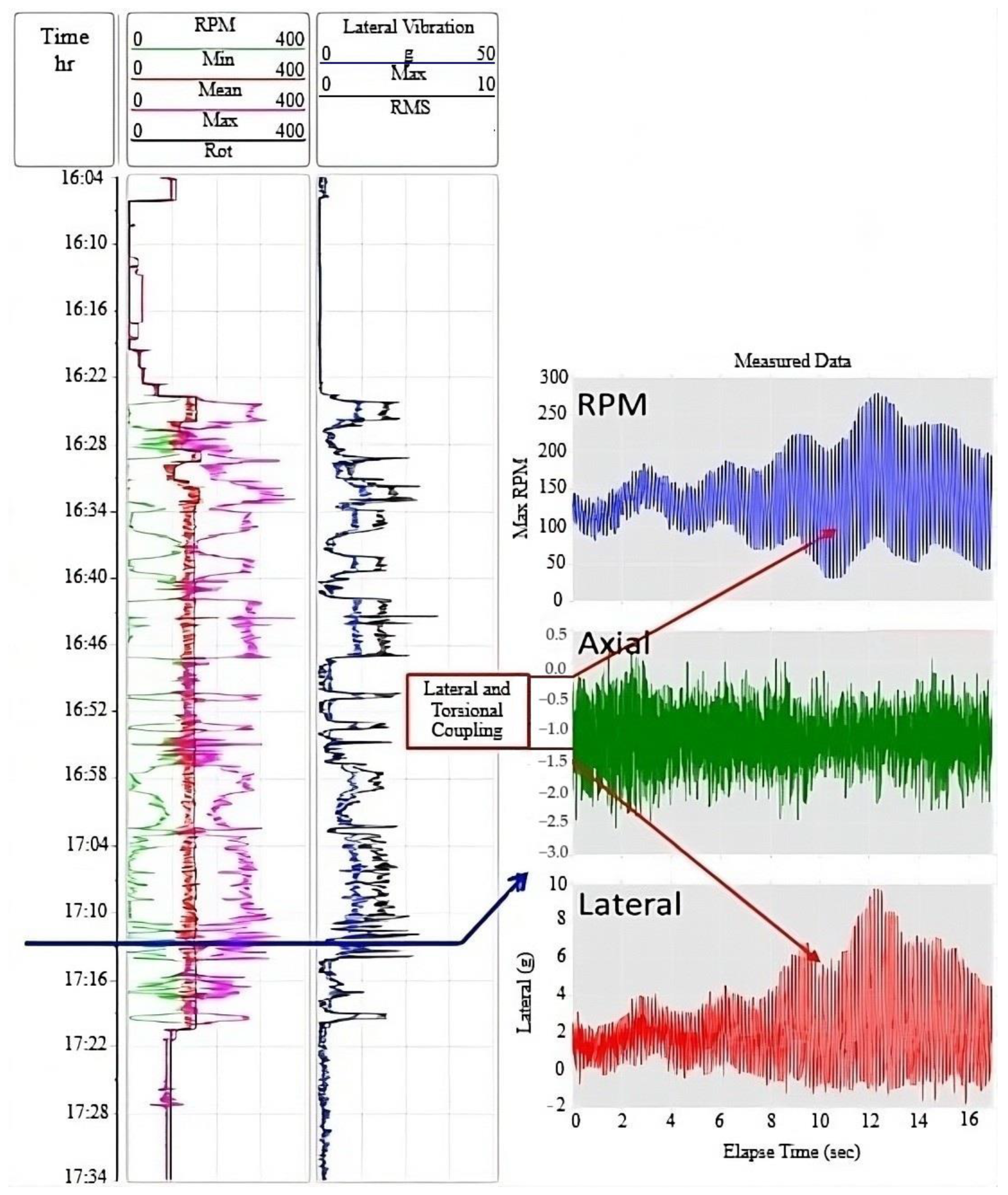
This section explores the modal frequencies of a drill string system with field-acquired measurement while drilling (MWD) data from an Algerian petroleum exploration oil well. Figure 6 illustrates a set of real-time drilling parameters, including torsional oscillation measurements (e.g., downhole angular velocity from a proprietary BlackBox sensor and rotary speed at the surface) and lateral displacement amplitudes (measured in terms of peak and root-mean-square values). Other logs of Figure 6 include WOB, surface Torque-on-Bit, ROP, Gamma Ray (GR), Mechanical Specific Energy (MSE), and computed Critical Compressive Strength (CCS) profile. One of the interesting observations from these logs at a depth of 1710 m is an increase in MSE and GR and a decrease in ROP, all occurring simultaneously. This intersection of the drilling signals postulates potentially coupled vibratory effects on the BHA. To further define this postulated dynamic interaction, a comprehensive time-domain analysis of downhole torsional, lateral, and axial accelerations was performed, presented as a function of burst acquisition time in Figure 7. It presents the frequency characteristics of the dynamic behavior of axial, torsional, and lateral vibrations observed in the drill string during drilling.
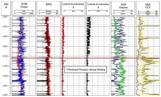
Figure 6.
Measurement of torsional and lateral accelerations in the studied oil well while drilling, the red horizontal line represent the extracted measurement at a depth of 1710 m.
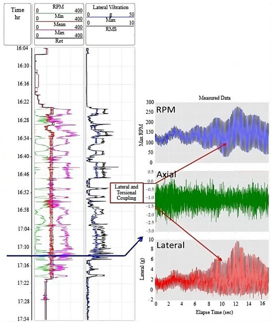
Figure 7.
Measurement of high-frequency axial–torsional–lateral vibration at specific depth.
The presence of high-frequency, high-amplitude vibration modes indicates stiff coupling among the axial, torsional, and lateral vibration modes, which may cause abrupt failure of drill string elements upon resonance, where the excitation frequency matches the system’s natural frequencies. Therefore, one needs to consider the natural frequencies of the drill string both analytically and through finite elements, as detailed in Section 5.
Although field data were shown to substantiate the occurrence of coupled axial–torsional–lateral vibrations, quantitative validation of the finite element model against such measurements was not attempted within this study. This is because there were not enough accurate boundary conditions, material characteristics, and sustained full-string acceleration measurements available to carry out high-fidelity correlation. However, field-measured frequency ranges and coupling behaviors are closely compared with model-calculated trends, serving as qualitative evidence of its applicability. Future work will focus on acquiring more extensive datasets, enabling direct numerical verification and calibration of the model to enhance its predictive quality and field relevance.
5. Finite Element Methods
A conventional drill string for vertical oil well drilling consists of a drill pipe, a heavy-weight drill pipe, a drill collar, and a drill bit. The top rotates at a constant angular velocity supplied by the top drive system and at a predefined axial speed corresponding to the desired rate of penetration (ROP). At the bottom, the weight on the bit and the torque on the bit are the primary forces acting on the drill bit. The drill string presented in this study is modeled as a rotating beam obeying the Euler–Bernoulli model. The finite element method discretizes the drill string into finite elements, allowing for axial, lateral, and torsional displacements at each node. The elementary mass, stiffness, and gyroscopic matrices are formulated based on [15] with the following assumptions:
- The material of the drill string is assumed to be homogeneous; elastic; and isotropic;
- Constant rotation around the neutral axis;
- At the surface, the drill string is fixed in both axial and lateral directions with a forced constant rotational speed;
- At the bottom, the drill bit can vibrate in the torsional direction while its lateral and axial motions are fixed.
The following elementary matrices were obtained by developing the kinetic and strain energy expressions [15], according to the extended Hamilton’s principle [24].
5.1. Mass Matrix
Based on Hamilton’s principle, Equation (1) is obtained to describe the mass matrix of an element in the drill string as
where is elementary mass matrix; is mass density; is the cross-sectional area; is element length; is area moment; is area polar moment of inertia; is the dimensionless length (); is a shape function that relates the vector of nodal displacements to the element displacement in axial , torsional and lateral directions & . These variables are written in matrix form as given by Equation (2).
The elements of the vector are defined in Equation (3).
Nu and Nθ are linear shape functions; Nv and Nw are cubic polynomial shape functions.
5.2. Gyroscopic Matrix
The mathematical expression of the gyroscopic matrix is described by Equation (4).
Ge is an elementary gyroscopic matrix; Ωt is a constant rotary speed. The gyroscopic matrix accounts for the gyroscopic effect that occurs where there is rotation. One can observe that the moment of inertia is greater than the gyroscopic effect for a rotating drill string [25], but the latter is more significant, especially when encountering drilling vibrations [16].
5.3. Stiffness Matrix
The stiffness matrix consists of two parts—elementary stiffness matrix Ke (given by Equation (5)) and geometric stiffness matrix Kge (given by Equation (6))—to account for axial loading [15].
is the initial deflection of the drill string at equilibrium position, and it depends on the system stiffness and external forces.
5.4. Forces Acting on the Drill String
In this study, the forces to which the drill string is subjected are the surface torque supplied by the top rotary system, the weight on the bit (given by Equation (7)), and the gravity force due to the weight of the drill string (Equation (8)). The damping forces caused by the drilling mud are not considered in the model.
Fr = WOB,
Fr is the axial loading.
is the gravity force vector for each element of the drill string.
5.5. Equation of Motion
After discretizing the drill string into smaller elements and formulating the elementary matrices, the equation of motion was obtained by assembling the local matrices into the global system matrices. The global coordinate vector q refers to the total system degree of freedom, which is equal to , where is the number of elements. The equation of motion is given in its general form by Equation (9).
is the global gravity force vector, M, G, and K are the global mass, gyroscopic, and stiffness matrices, respectively. The surface torque is introduced in the model as a constant rotary speed. To obtain the natural frequencies of the drill string, the right-hand side of Equation (9) is assumed to be equal to zero, and the matrices G and Kg are excluded. Hence, Equation (9) is reduced to Equation (10).
For the boundary conditions, the top rotary system fixes the drill string’s top extremity in three directions. At the bottom, the lateral and axial displacements of the drill bit are restrained while its torsional motion is free. Therefore, the natural frequencies and corresponding mode shapes can be obtained by solving the generalized eigenvalue problem given by Equation (11).
ω is the eigenvalue and ϕ is the eigenvector, K and M are the global reduced stiffness and mass matrices after applying the boundary conditions.
6. Analytical Models
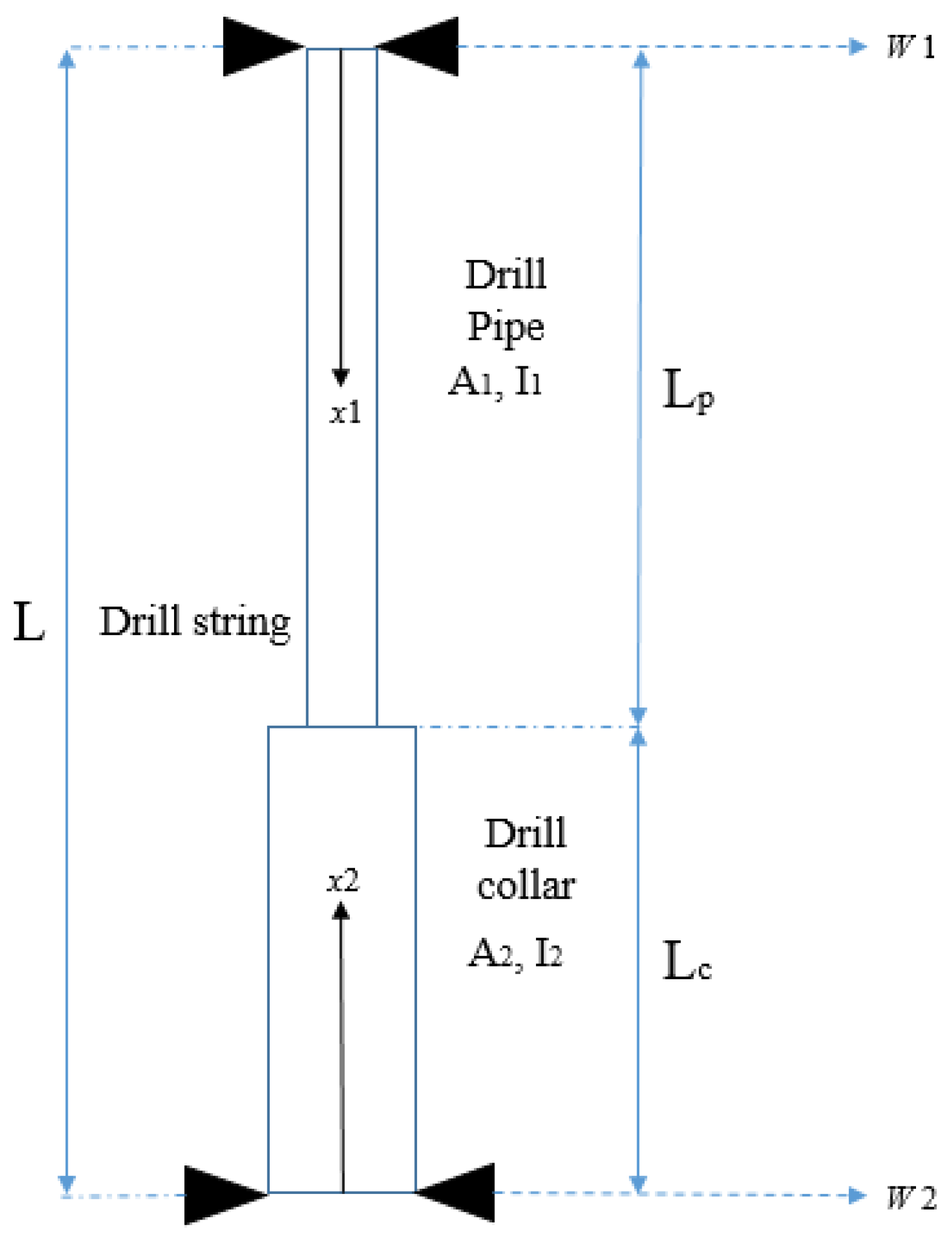
This section introduces the analytical models for lateral, axial, and torsional vibrations, which were developed to assess the reliability of finite element models in estimating the natural frequencies of the drill string. Each analytical model is formulated separately based on Newton’s second law and Hamilton’s principle [24]. The drill string is approximated as a stepped beam with two different cross-sections and lengths, as shown in Figure 8. Stress concentration at the interface between the drill pipe and drill collar is neglected. In addition, continuity boundary conditions at the interface are verified and satisfied.
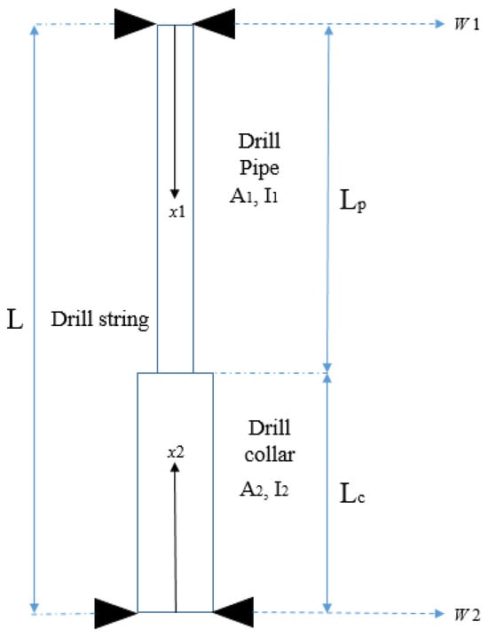
Figure 8.
Drill string approximated as a stepped beam.
6.1. Lateral Vibrations Model
For a drill string approximated as a uniform Euler–Bernoulli beam and freely vibrating in the transverse direction, the governing equation of motion is given by Equation (12).
With is the lateral displacement expressed by Equation (13) [24].
Injecting Equation (13) into (12) and rearranging the terms, this gives Equation (14).
For a drill string approximated as a stepped beam, Equation (14) can be rewritten as in Equation (15).
where is the dimensional frequency coefficient, and i denotes the part considered (drill pipe or drill collar). The term in Equation (15) is given by Equation (16).
The interface between the drill pipe and the drill collar must satisfy the continuity boundary conditions, such as the continuity of deflection, slope, moment, and shear force all given by Equation (17) [26].
Formulating the above boundary conditions, one obtains the determinant that must vanish to obtain a non-trivial solution as shown in Equation (18) [26].
Based on solving Equation (18), we obtained the values as given in Equations (19) and (20).
S1 = sin β1Lp, SH1 = sinh β1Lp, C1 = cos β1Lp, CH1 = cosh β1Lp,
S2 = sin β2Lc, SH2 = sinh β2Lc, C2 = cos β2Lc, CH2 = cosh β2Lc,
6.2. Axial Vibrations Model
For the axial model, the natural frequencies of the drill string were obtained using the equation of motion derived from Hamilton’s principle as given by Equation (22).
where u is given by Equation (22).
Substituting (22) in (21) and rearranging the terms, Equations (23) and (24) are obtained.
The general solution of Equation (24) for an axially vibrating drill string is given by Equation (25).
The constants of Equation (25) are selected by applying the boundary conditions given in Equation (26).
The interface must satisfy the continuity boundary conditions, so that Equation (27) is satisfied.
From Equations (26) and (27), one obtains the determinant that must vanish to find a non-trivial solution as demonstrated in Equation (28).
where
6.3. Torsional Vibrations Model
The natural frequencies of the drill string in the torsional model were estimated using the equation of motion given by (29) [24].
Θ is the torsional displacement.
The general solution of Equation (29) is pretty similar to (19) by substituting E, A and U with G, I0, and Θ, respectively. Hence, Equation (30) is obtained.
where
The boundary conditions for this model are given by Equation (31).
From Equations (30) and (31), the determinant below is set to zero to avoid a trivial solution as demonstrated in Equation (32).
where .
Equations obtained from the three above determinants (lateral, axial, and torsional models) are solved using the modified half-interval method developed in Matlab 2024a environment, and the first seven roots are selected.
To approximately model the real geometry of the drill string, a stepped beam approach was employed in this section to represent the transitions between the drill pipes and the drill collars. The boundary conditions and material properties were idealized for simplicity. It must be noted that drill pipe joints were not modeled directly in the model. This simplification was made to focus on the principal structural effects of various drill pipe and drill collar lengths. While the joints may induce local stiffness variations or contact nonlinearities, their effect on global natural frequencies is generally low, especially when the drill string is represented by large lengths and for low-order modes. However, we appreciate that under certain conditions, high-frequency localized modes or in studies for fatigue or contact behavior, joint effects will be of greater significance. Additional research could then elaborate on the existing model to add finer joint descriptions or contact interfaces, thereby enhancing accuracy in such cases.
7. Results and Discussion
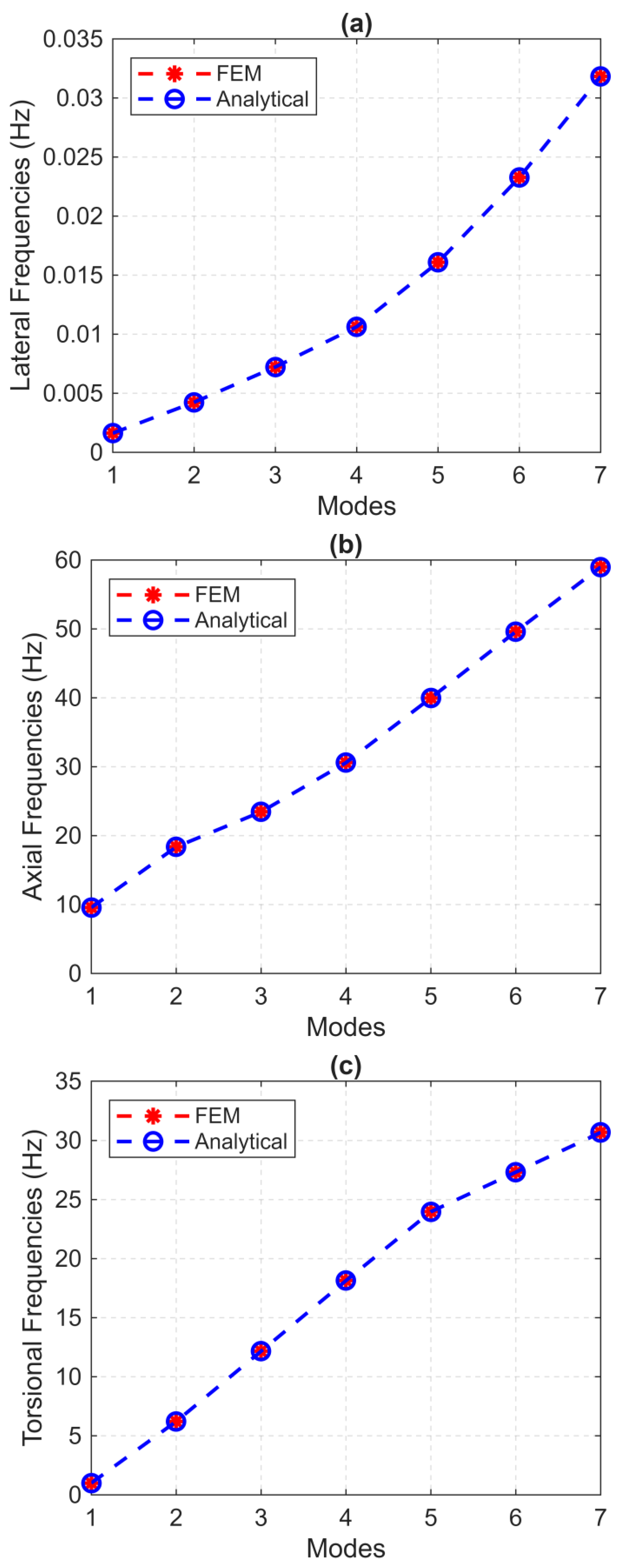
This section discusses the efficiency of the current finite element model in estimating the natural frequencies of the entire drill string, and a comparison with analytical models is performed. The drill string used for the comparison was composed, for the first time, of 1620 m of drill pipe and 360 m of drill collar. Table 1 summarizes the properties of the retained drill string for the base case scenario.

Table 1.
Drill string specifications (base case scenario) [15].
The drill pipes in the finite element model were discretized into 180 elements, each with a length of 9 m. As to the second part, an element length of 2 m was used to discretize the drill collars into 180 elements. The first seven natural frequencies were calculated using both models, and the results are plotted in Figure 9. As can be seen, the natural frequencies estimated by the finite element models coincide with those calculated by the analytical models for all the seven considered modes (lateral mode in Figure 9a, axial mode in Figure 9b, and torsional mode in Figure 9c). This shows that finite element models can be a very practical alternative to analytical models. This similarity can be leveraged to support the development of more complex finite element models that accurately describe the real behavior of the drill string under more realistic field conditions [33].
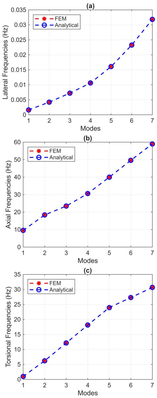
Figure 9.
Natural frequencies estimation from FEM and analytical models: (a) lateral, (b) axial, and (c) torsional vibrations.
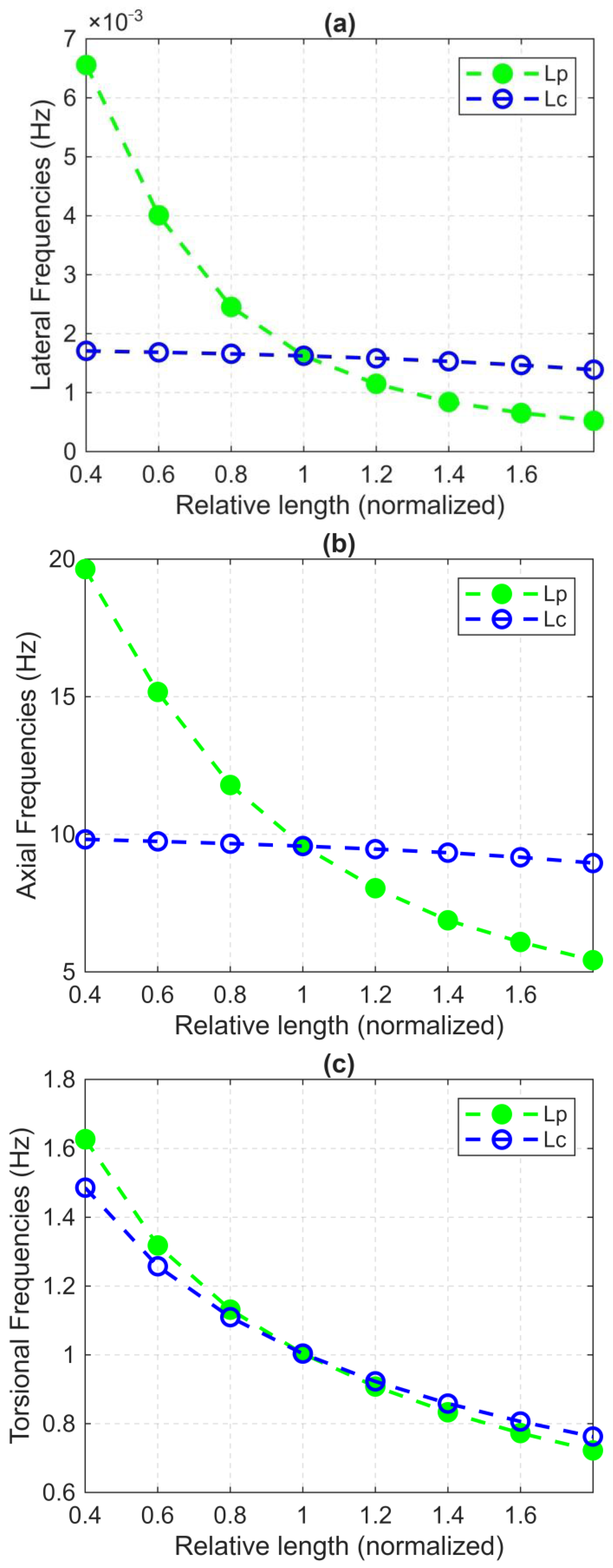
This investigation analyzes the effects of drilling parameters on the natural frequencies of the drill string. The length of the drill pipe and drill collar are the main drilling parameters considered. Each parameter is divided by its base case (given in Table 1) to obtain a normalized ratio. Then, the variation in the first natural frequency is plotted versus the normalized ratio. To reproduce the actual drilling process, the length of the drill string was increased by adding additional drill pipes while maintaining the length of the drill collars as shown in Figure 10.
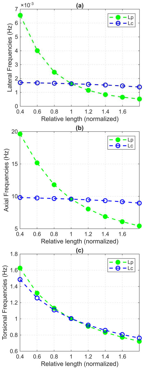
Figure 10.
Effect of varying total length of drill pipes and drill collar on the first natural frequencies for (a) lateral, (b) axial, and (c) torsional vibrations.
Figure 10 shows that the total length of the drill pipes is a predominant parameter affecting the drill string’s natural frequencies in lateral, axial, and torsional vibrational modes. It can be observed that increasing the total length of drill pipes from 1 to 1.8 times the base value has resulted in a 62.44% decrease in the first lateral natural frequency, a 39.47% decrease in the first axial natural frequency, and a 5.31% decrease in the first torsional natural frequency.
Table 2 summarizes the absolute and percentage errors for the first frequency modes for lateral, axial, and torsional dynamics. The absolute error is calculated using Equation (33).
Table 2.
Absolute and percentage errors for lateral, axial, and torsional first natural frequencies.
The relative error is calculated using Equation (34).
Increasing the total drill pipe and drill collar length from 0.4 to 1.8 affects the lateral and axial natural frequencies. A decrease of 10.54% in the axial natural frequency was obtained against 11.53% in the lateral natural frequency. This can be interpreted by the fact that as the length of drill collars increases, the ratio length to weight tends to be constant, leading to slight changes in natural frequencies. For the torsional vibration mode, the natural frequencies of drill collars follow the same descending curve as those of drill pipes as the total length increases. A 3.34% decrease in the torsional natural frequency was observed. It must also be noted that the variation in the relative normalized length of the drill pipe has not a considerable effect on the first natural frequency of torsional vibrations when compared to lateral and axial vibrations. This is mainly due to the nature of torsional dynamic, which is directly related to the rotational behavior of the drill string and the applied surface torque regardless of the drill string length and configuration.
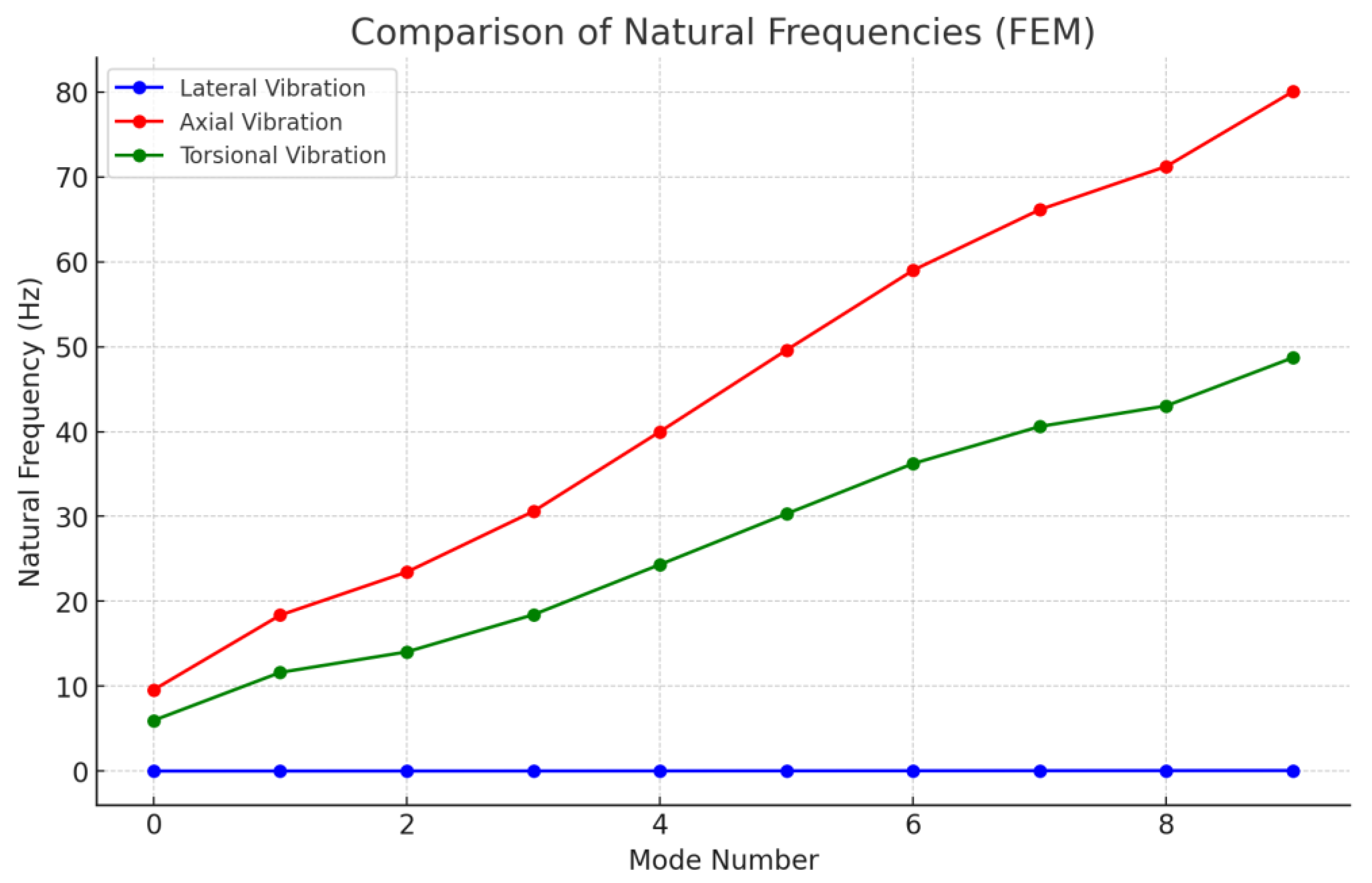
Figure 11 shows the effect of varying the number of modes on the natural frequencies of lateral, axial, and torsional vibrations. As observed, the number of modes has no pronounced effect on the natural frequencies of lateral vibrations. This may be because this type of vibration does not generate propagating waves that can fluctuate along the drill string axis. However, torsional vibrations are affected by the number of modes; an increase in the number of modes leads to more natural frequencies of torsional vibrations. This effect may be due to the interaction between axial and torsional vibrations and how one can influence the other. Axial vibrations are strongly affected by the number of modes, with a significant increase compared to torsional vibrations, especially for higher frequency modes. This is because such vibrations mainly occur within the drill string and propagate through it in most scenarios.
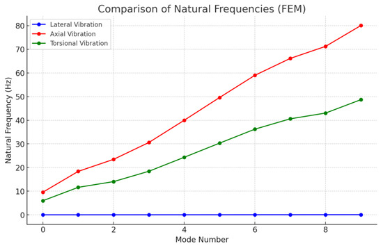
Figure 11.
Effect of varying the mode number on the natural frequencies of lateral, axial, and torsional vibrations.
The predominance of higher axial modes of vibration can be physically interpreted in terms of the longitudinal wave propagation of the drill string. Axial vibrations generate compressive and tensile waveforms along the axis of the string, and their natural frequencies depend closely upon the effective mass distribution and stiffness. As the drill pipe is longer, the structure is more flexible axially, resulting in a smaller natural frequency due to a larger wave propagation distance and increased modal mass. Also, since axial wave propagation is not significantly affected by bending stiffness, it exhibits more severe mode separation than lateral vibrations. In modal analysis terms, each vibration mode is correlated with a specific pattern or shape of deformation along the drill string. In lateral vibration, the first mode is commonly a simple sinusoidal with one node near the middle; however, with increasing order, additional inflection points and nodes are created.
The torsional modes are characterized by rotation around the longitudinal axis, and higher torsional modes indicate more complicated distributions of torsional strain. The axial modes are standing wave patterns with nodes specified by boundary constraints and mass distribution. Understanding these modal shapes is crucial in determining where maximum stress concentrations are likely to occur and, therefore, in idealizing the placement of stabilizers and sensors for real-time monitoring. The implications of these results emphasize the need for realistic boundary conditions and geometry to be incorporated into finite element models, thereby enhancing the prediction of dynamic behavior.
Based on the results obtained from Figure 11, the natural frequency analysis of the drill string under coupled axial–torsional–lateral vibrations indicates that both analytical and numerical models yield similar results. Specifically, axial vibrations tend to dominate over torsional and lateral vibrations. Therefore, it is highly recommended to consider high-frequency coupled axial–torsional–lateral vibrations in the design and analysis of drill strings. Resonance phenomena, where vibration frequencies overlap with natural frequencies, can lead to unexpected and uncontrolled damage to drill string equipment if not carefully and robustly analyzed.
8. Limitations of the Study and Directions for Further Work
While the present work contributes to analyzing the stepped drill strings’ natural frequencies under coupled axial–torsional–lateral vibrations, certain limitations are observed that may influence the generalizability and accuracy of the results.
First, the finite element model relies on a linear elastic response and does not account for damping effects from the drilling mud. Under real drilling conditions, the interaction between the drill string and the fluid plays a significant role in damping vibrations and dissipating energy. Models of fluid–structure interaction and mud damping contribute to the realism and predictability of the simulations.
Secondly, the bit–rock interaction was ideally modeled, but the influence of complex, nonlinear contact forces was not included. It is recommended that future research incorporates nonlinear boundary conditions and torque-on-bit feedback mechanisms to simulate more accurate bit vibration responses and effectively model stick-slip phenomena.
Third, the model calculates geometry as a stepped beam but fails to account for joint effects, tool face misalignment, and local stiffness variations due to pipe connections and wear. These considerations can be included to allow the model to predict localized resonance and stress concentrations more effectively.
Fourth, the FEM and analytical models were not quantitatively validated against measured downhole data due to the insufficient availability of field parameters, including full acceleration logs, boundary condition profiles, and accurate material properties. Complete MWD/LWD data must be obtained in subsequent studies, and experimental validation or field correlation must be conducted to build confidence in the model prediction.
Lastly, while the current effort focused on nonlinear deterministic modal analysis to estimate natural frequencies, it does not address probabilistic dynamic responses and uncertainty analysis that might arise during drilling. The incorporation of probabilistic modeling can provide a more comprehensive picture of drill string dynamics, incorporating actual operating uncertainties.
In the future, the implementation of such concepts in both numerical and analytical models will enhance the credibility of vibration analysis. These developments are crucial for enhancing smart drilling system design and ensuring mechanical reliability in adverse downhole environments.
9. Conclusions
This study conducted a broad comparison between analytical and finite element models of approximating the natural frequencies of a drill string, taking a model drill string configuration as a case study. To better represent the geometry of the drill string, particularly the drill pipe–drill collar transition, the string was modeled as a stepped beam rather than a uniform beam. This research paper established that lateral natural frequencies are highly sensitive to the change in drill pipe length. This sensitivity might be avoided using stabilizers at the drill pipe–drill collar interface, thereby enhancing lateral vibration control. For the torsional vibration mode, the drill collars and drill pipes influenced the natural frequencies of the drill string, further highlighting the significance of component interaction.
Finite element models were found to be very efficient in the prediction of natural frequencies under realistic boundary conditions. Compared with analytical models, finite element methods were more adaptable and flexible in modeling representative drill string behavior under coupled axial–torsional–lateral vibration conditions. These findings highlight the necessity of using strong numerical models in analyzing drill string vibration and predicting critical resonant frequencies to avert vibration-induced failure in drilling operations. However, it is essential to note that the finite element model used in this study does not account for dynamic damping effects introduced by the drilling mud. Simplifications were made to disconnect significant structural and geometric factors that impact the natural frequencies of the drill string and reduce computational complexity. Even though such effects will produce limited influences on global modal properties, they would be of great importance in high-frequency ranges or system responses near the bit. Modeling drill pipe joints and coupled local stiffness changes, such as fluid–structure interaction with mud damping, would yield a deeper understanding of drill string vibrations. Further, the experimental validation of numerical calculations or field measurements would increase confidence in model applications. Such improvements would contribute to the development of more energy-efficient and long-lived drilling systems for challenging operating conditions. Improving the prediction and control of drill string vibrations has a direct, related effect on enhancing the energy efficiency and mechanical longevity of drilling systems, which is closely related concern in the context of cost-effective resource recovery in the petroleum industry.
Funding
This research received no external funding.
Data Availability Statement
The data presented in this study are not publicly available due to restrictions. However, the data can be made available from the corresponding author upon reasonable request.
Conflicts of Interest
The author declare no conflict of interest.
References
- Murthy, G.V.S.; Das, G.; Das, S.K.; Parveen, N.; Singh, S.R. Hardbanding failure in a heavy weight drill pipe. Eng. Fail. Anal. 2011, 18, 1395–1402. [Google Scholar] [CrossRef]
- Kriesels, P.C.; Keultjes, W.J.G.; Dumont, P.; Huneidi, I.; Owoeye, O.O.; Hartmann, R.A. Cost savings through an integrated approach to drillstring vibration control. In Proceedings of the SPE/IADC Middle East Drilling Technology Conference, Abu Dhabi, United Arab Emirates, 8–10 November 1999. [Google Scholar] [CrossRef]
- Zamani, S.M.; Hassanzadeh-Tabrizi, S.A.; Sharifi, H. Failure analysis of drill pipe: A review. Eng. Fail. Anal. 2016, 59, 605–623. [Google Scholar] [CrossRef]
- Ghasemloonia, A.; Rideout, D.G.; Butt, S.D. A review of drillstring vibration modeling and suppression methods. J. Pet. Sci. Eng. 2015, 131, 150–164. [Google Scholar] [CrossRef]
- Chen, P.; Meng, M.; Ren, R.; Miska, S.; Yu, M.; Ozbayoglu, E.; Takach, N. Modeling of PDC single cutter—Poroelastic effects in rock cutting process. J. Pet. Sci. Eng. 2019, 183, 106389. [Google Scholar] [CrossRef]
- Bailey, J.R.; Biediger, E.A.O.; Gupta, V.; Ertas, D.; Elks, W.C.; Dupriest, F.E. Drilling vibrations modeling and field validation. In Proceedings of the IADC/SPE Drilling Conference, Orlando, FL, USA, 4–6 March 2008. [Google Scholar] [CrossRef]
- Germay, C.; Denoël, V.; Detournay, E. Multiple mode analysis of the self-excited vibrations of rotary drilling systems. J. Sound Vib. 2009, 325, 362–381. [Google Scholar] [CrossRef]
- Cao, J.; Zou, D.; Xue, Q.; Wang, J.; Huang, L.; Guo, F.; Wang, C.; Qu, J. Analysis on the dynamics of flexible drillstring under different drilling parameters. Front. Earth Sci. 2024, 12, 1396784. [Google Scholar] [CrossRef]
- Tian, J.; Liu, Y.; Xiong, J.; Wen, F.; Liu, G. Analysis of Drill String’s Vibration Characteristics Based on Sliding Mode-PI Controller. J. Vib. Eng. Technol. 2022, 10, 919–927. [Google Scholar] [CrossRef]
- Navarro-López, E.M.; Cortés, D. Avoiding harmful oscillations in a drillstring through dynamical analysis. J. Sound Vib. 2007, 307, 152–171. [Google Scholar] [CrossRef]
- Yigit, A.S.; Christoforou, A.P. Coupled torsional and bending vibrations of drillstrings subject to impact with friction. J. Sound Vib. 1998, 215, 167–181. [Google Scholar] [CrossRef]
- Riane, R.; Doghmane, M.Z.; Kidouche, M.; Djezzar, S. Observer-Based H∞ Controller Design for High Frequency Stick-Slip Vibrations Mitigation in Drill-String of Rotary Drilling Systems. Vibration 2022, 5, 264–289. [Google Scholar] [CrossRef]
- Hutchinson, M.; Dubinsky, V.; Henneuse, H. An MWD downhole assistant driller. In Proceedings of the SPE Annual Technical Conference and Exhibition, Dallas, TX, USA, 22–25 October 1995. [Google Scholar] [CrossRef]
- Ghasemloonia, A.; Rideout, D.G.; Butt, S.D. Vibration analysis of a drillstring in vibration-assisted rotary drilling: Finite element modeling with analytical validation. J. Energy Resour. Technol. 2013, 135, 032902. [Google Scholar] [CrossRef]
- Al Dushashi, M.F.; Nygaard, R.; Stutts, D.S. An analysis of common drill stem vibration models. J. Energy Resour. Technol. 2018, 140, 012905. [Google Scholar] [CrossRef]
- Khulief, Y.A.; Al-Sulaiman, F.A.; Bashmal, S. Vibration analysis of drillstrings with self-excited stick–slip oscillations. J. Sound Vib. 2007, 299, 540–558. [Google Scholar] [CrossRef]
- De Moraes, L.P.P.; Savi, M.A. Drill-string vibration analysis considering an axial-torsional-lateral nonsmooth model. J. Sound Vib. 2019, 438, 220–237. [Google Scholar] [CrossRef]
- Volpi, L.P.; Lobo, D.M.; Ritto, T.G. A stochastic analysis of the coupled lateral–torsional drill string vibration. Nonlinear Dyn. 2021, 103, 49–62. [Google Scholar] [CrossRef]
- Qiu, H.; Yang, J. Stochastic and Deterministic Vibration Analysis on Drill-String With Finite Element Method. In Proceedings of the ASME 2013 International Mechanical Engineering Congress and Exposition, San Diego, CA, USA, 15–21 November 2013. [Google Scholar] [CrossRef]
- Meddah, S.; Tadjer, S.A.; Idir, A.; Tee, K.F.; Doghmane, M.Z.; Kidouche, M. Dynamic Interaction Analysis of Coupled Axial-Torsional-Lateral Mechanical Vibrations in Rotary Drilling Systems. Struct. Durab. Health Monit. 2025, 19, 77–103. [Google Scholar] [CrossRef]
- Guo, X.; Yang, K.; Hu, N.; Zhao, L.; Li, X. Multiple nonlinear vibration model of drilling string and mechanism of drilling speed increase in ultra-HPHT oil & gas wells. Nonlinear Dyn. 2025, 113, 6335–6376. [Google Scholar] [CrossRef]
- Mahjoub, M.; Nguyen, K.-L.; Dao, N.-H.; Menand, S.; Endres, L.; Cheng, C.; Mada, H.; Feng, X.; Sun, J. From Bit-Rock Interaction to BHA Vibration: Experimental and Numerical Perspectives. In Proceedings of the SPE/IADC International Drilling Conference and Exhibition, Stavanger, Norway, 4–6 March 2025. Paper SPE-223744-MS. [Google Scholar] [CrossRef]
- Bondarenko, A.V.; Islamov, S.R.; Ignatyev, K.V.; Mardashov, D.V. Laboratory studies of polymer compositions for well-kill under increased fracturing. Perm J. Pet. Min. Eng. 2020, 20, 37–48. [Google Scholar] [CrossRef]
- Wu, J.-S. Analytical and Numerical Methods for Vibration Analyses; John Wiley & Sons: Hoboken, NJ, USA, 2013. [Google Scholar]
- Khulief, Y.A.; Al-Naser, H. Finite element dynamic analysis of drillstrings. Finite Elem. Anal. Des. 2005, 41, 1270–1288. [Google Scholar] [CrossRef]
- Jang, S.K. Free vibration of stepped beams: Exact and numerical solutions. J. Sound Vib. 1989, 130, 342–346. [Google Scholar] [CrossRef]
- Real, F.F.; Batou, A.; Ritto, T.G.; Desceliers, C. Stochastic modeling for hysteretic bit–rock interaction of a drill string under torsional vibrations. J. Vib. Control 2019, 25, 1663–1672. [Google Scholar] [CrossRef]
- Chen, J.; Liao, H.; Zhang, Y.; Liang, H.; Liu, C.; Qi, D. A torsional-axial vibration analysis of drill string endowed with kinematic coupling and stochastic approach. J. Pet. Sci. Eng. 2021, 198, 108157. [Google Scholar] [CrossRef]
- Tao, Z.; Meng, Y.; Feng, Q.; Yang, K.; Kang, W.; Huang, X.; Fang, P. Analysis of nonlinear vibration of lateral-torsional coupling for drill string in deviated well. J. Vibroeng. 2024, 26, 1584–1599. [Google Scholar] [CrossRef]
- Guo, X.Q.; Liu, J.; Wang, J.X.; Dai, L.M. Investigation on axial-lateral-torsion nonlinear coupling vibration characteristic of drilling string in ultra-HPHT curved wells. In Proceedings of the IOP Conference Series: Earth and Environmental Science, Surakarta, Indonesia, 25–27 February 2021; Volume 861, p. 052050. [Google Scholar] [CrossRef]
- Liu, J.; Liang, S.; Chen, Y.; Zhang, M. Axial-lateral-torsional coupling nonlinear vibration of riserless drill-string considering both seawater and stratum parts. Appl. Ocean Res. 2023, 140, 103742. [Google Scholar] [CrossRef]
- Ren, F.; Wang, B.; Chen, S. Nonlinear Modeling and Qualitative Analysis of Coupled Vibrations in a Drill String. Int. J. Bifurc. Chaos 2018, 28, 1850119. [Google Scholar] [CrossRef]
- Belousov, A.; Lushpeev, V.; Sokolov, A.; Sultanbekov, R.; Tyan, Y.; Ovchinnikov, E.; Shvets, A.; Bushuev, V.; Islamov, S. Experimental Research of the Possibility of Applying the Hartmann–Sprenger Effect to Regulate the Pressure of Natural Gas in Non-Stationary Conditions. Processes 2025, 13, 1189. [Google Scholar] [CrossRef]

Disclaimer/Publisher’s Note: The statements, opinions and data contained in all publications are solely those of the individual author(s) and contributor(s) and not of MDPI and/or the editor(s). MDPI and/or the editor(s) disclaim responsibility for any injury to people or property resulting from any ideas, methods, instructions or products referred to in the content. |
© 2025 by the author. Licensee MDPI, Basel, Switzerland. This article is an open access article distributed under the terms and conditions of the Creative Commons Attribution (CC BY) license (https://creativecommons.org/licenses/by/4.0/).