1. Introduction
The reduction in CO
2-equivalent emissions from residential buildings is an increasingly urgent challenge [
1]. However, as the number of buildings continues to rise [
2], achieving future emission reduction targets becomes even more demanding. This calls for drastic measures and innovative strategies to enhance energy efficiency and sustainability in the built environment.
One of the most effective solutions for reducing the environmental impact of heating and cooling in buildings is the use of reversible heat pumps/air conditioning units. These systems, when powered by electricity from renewable sources, provide a sustainable alternative to traditional climate control methods, significantly lowering greenhouse gas emissions while improving energy efficiency [
3].
In recent years, heat pumps have undergone significant technological advancements, becoming a key solution for the decarbonization of building heating and cooling systems [
4]. Their widespread adoption has also been supported by decarbonization policies and financial incentives. Recent studies have highlighted improvements in the efficiency and versatility of these technologies. For instance, the integration of heat pumps with combined systems for cooling, heating, and power generation has led to energy savings of up to 40.6% for cooling and 28.5% for heating, along with a 39.6% reduction in CO
2 emissions [
5]. Another study on geothermal heat pumps for the retrofit of school buildings reported up to a 45% reduction in CO
2 emissions, with a positive economic return within 7 years, making such solutions competitive even in the public sector [
6].
However, a major challenge in utilizing heat pumps with renewable energy lies in the temporal mismatch between the energy availability and user demand [
7]. Renewable energy production does not always coincide with peak heating or cooling needs, making energy storage a fundamental requirement [
8]. Energy can be stored either in the form of electricity or as thermal energy, with the latter being a promising approach when integrated with heat pump systems [
9].
Latent thermal energy storage (LTES) systems, which use Phase Change Materials (PCMs) to store and release energy, offer a higher energy storage density per unit volume compared to conventional sensible heat storage methods (e.g., water tanks). These systems can be designed in various configurations to adapt to different spatial and technical constraints in buildings [
10,
11]. When integrated with HP/AC units and renewable energy sources, LTES systems can optimize energy utilization, balancing supply and demand more effectively [
12,
13].
The selection of a suitable PCM is a critical aspect of LTES system design [
14,
15,
16]. Different PCM families exhibit varying thermal properties, advantages, and limitations, and the chosen phase change temperature significantly influences the overall system efficiency [
17]. Additionally, factors such as environmental sustainability and material cost must be considered [
16]. Beyond the material selection, the design of the storage unit itself is equally complex. Most PCMs present low thermal conductivity, which often necessitates the use of metallic elements such as fins, corrugations, inserts, or nanoparticles to enhance the heat transfer. The optimal storage configuration depends on the specific thermal power requirements of the application [
18,
19,
20].
A key issue with current LTES solutions is that most commercially available storage units are standalone products rather than being integrated with heat pumps and adapted to specific use scenarios. This is particularly problematic for systems operating under partial load conditions, where the dynamic behavior of the HP/AC unit is directly affected by the thermal response of the LTES [
21,
22]. More than traditional water-based sensible heat storage, the performance of integrated LTES systems is highly dependent on precise regulation and control strategies tailored to efficiently manage the thermal energy storage [
23,
24].
Several studies have investigated the integration of latent thermal energy storage (LTES) with heat pump systems, emphasizing its potential to improve energy efficiency and support flexible operation strategies. Saleem et al. [
22] provided a comprehensive review of energy storage-integrated ground-source heat pumps, highlighting their applicability for both heating and cooling scenarios and identifying key challenges in system design and control. Wang et al. [
25] discussed control strategies for cold thermal energy storage in cooling systems, underlining the importance of dynamic regulation to avoid performance degradation and improve load matching. Safari et al. [
26] experimentally analyzed different fin configurations in LTES units and showed how design parameters influence thermal responses under various flow and orientation conditions, a factor that becomes critical when operating in conjunction with heat pumps under real-world, non-ideal load profiles.
In recent years, the study of PCMs for cold thermal energy storage has attracted growing interest due to their high energy density and potential for enhancing the performance of energy systems. However, the majority of research in this field remains focused on applications related to heating needs, with relatively few studies addressing cooling-oriented systems [
27,
28].
Some particularly relevant examples can be highlighted. Akbari et al. [
29] investigated an LTES system coupled with an air conditioning unit, conducting a detailed thermo-economic optimization to evaluate the system performance and cost-effectiveness. Li D. et al. [
30] proposed a sustainable system that combines a solar and ground-source heat pump heating system with a latent heat storage tank, aiming to replace a conventional oilfield hot water station. Li W. et al. [
31] carried out an experimental study on a PCM-based shell-and-tube latent heat storage unit designed for integration with a heat pump system, analyzing its performance and energy storage capabilities.
Despite this, there is still a limited understanding of how the heat pump (or AC units) behavior under a part-loading operation is affected when coupled with a latent heat storage system [
32].This gap in knowledge presents an opportunity for further research to optimize the integration of LTES with HP/AC systems, paving the way for more efficient, sustainable, and adaptive climate control solutions in residential buildings.
The integration of LTES with HP/AC systems is particularly relevant for residential applications, where the cooling demand typically peaks in the early afternoon and drops significantly during the night [
13]. This characteristic load profile makes cold thermal storage an effective solution for peak load shaving and load shifting, helping to reduce energy consumption during periods of high electricity prices or grid stress [
9]. Moreover, different types of end users impose different requirements on the system: small residential units may demand low cooling capacity for extended periods, while larger dwellings or office spaces may require a higher power over shorter durations [
9]. These variations influence the necessary design of the LTES system, including the storage capacity, heat exchange rate, and control strategy. The configuration tested in this study—with relatively slow charge/discharge dynamics—is particularly suitable for maintaining thermal comfort in residential environments where temperature fluctuations must be minimized over several hours, rather than responding to short-term demand peaks [
33].
Aim of This Study
Despite this growing body of research, the experimental validation of commercial-scale LTES systems under realistic, variable thermal loads remains limited. The present study addresses this gap by coupling a commercially available LTES tank with a market-ready HP/AC unit operating with an R32 refrigerant and evaluating the system behavior under real operating conditions. These include the compressor frequency modulation, cooling capacity fluctuations, and part-load cycling—factors not captured in studies relying on constant boundary conditions.
The specific innovation of the present study lies in testing the thermal storage system under actual operational conditions with a commercial HP/AC unit. Unlike constant-load characterization methods, this approach provides more realistic insights into system interactions, the dynamic load response, and control issues. Such analysis is essential to avoid a suboptimal operation—such as inefficient cycling or a low COP—in real-world applications. Furthermore, the experimental data collected support the co-design of HP and LTES systems, enabling optimized sizing, better energy management, and increased applicability in residential cooling scenarios.
Specifically, it examines the summer cooling season, where the HP/AC operates in cooling mode, and low-temperature heat storage is required. To optimize the cooling demand by the final user at approximately 15 °C, a PCM with a melting point around 9 °C was selected. An LTES system with a thermal capacity of about 18 kWh was studied. This system utilizes approximately 300 kg of a bio-based PCM with a melting temperature of 9 °C. Its performance was analyzed under two conditions: when powered by a thermostatic water circuit from a thermostatic bath and when connected to a commercially available water-to-water HP/AC unit with a variable-speed compressor and a nominal cooling capacity of 5 kW. The novelty of this study lies in highlighting the differences in the behavior of the storage system under these two configurations. This comparison provides critical insights to model and optimize LTES units, facilitating their integration with heat pumps in residential buildings. The findings contribute to the development of more efficient, sustainable, and accessible heating and cooling solutions for the residential sector.
2. Setup Description and Data Reduction
The experimental setup, represented in
Figure 1, is designed to analyze the synergistic operation of a HP/AC unit coupled with an LTES system. This study focuses on the combined performance of these components, with a particular emphasis on summer cooling conditions.
The PCM-based latent thermal energy storage (LTES) is directly connected to the load-side hydronic loop of the water-to-water HP/AC unit. In this configuration, the LTES receives the entire cooling output of the unit during the charging phase. No other terminal units (e.g., fan coils or radiators) are connected, and therefore the storage acts as the sole thermal sink. The original water-side terminals of the AC unit were replaced by the PCM module to allow the full control of thermal boundary conditions and to isolate the performance of the storage system. The source side of the heat pump is simulated by a thermostatic bath, while the entire setup operates inside a climate-controlled chamber maintained at 20 °C.
2.1. HP/AC Unit
The HP/AC unit is a reversible water-to-water system available on the market (Innova s.r.l. 3in1 GEO WW Incasso 9M heat pump, Rome, Italy).
For this study, it is configured in the summer mode to chill water at a setpoint of 2 °C to charge the LTES. The unit features two brazed plate heat exchangers serving as the condenser and evaporator, an inverter-driven rotary compressor, and an electronic throttling valve. The brazed plate evaporator was designed in order to achieve a 2 K temperature approach between the evaporation temperature and the water outlet temperature.
The electric power consumption of the HP/AC unit, including the circulation pump and auxiliaries, was measured using a digital power meter with ±1% accuracy. Thermocouples with an uncertainty equal to ±0.1 °C were used to measure the ground source water temperature (set at 15 °C) and the temperature of the water at the inlet of the LTES (set point 2 °C). A thermopile (uncertainty ±0.05 °C) measured the water temperature difference between the inlet and outlet of the LTES side, while the flow rate was maintained at 16 L/min and measured by means of an Endress + Houser Promag H electromagnetic flow meter (Endress + Houser, Reinach, Switzerland) (±0.5% accuracy, full scale 40 L min−1).
2.2. LTES System
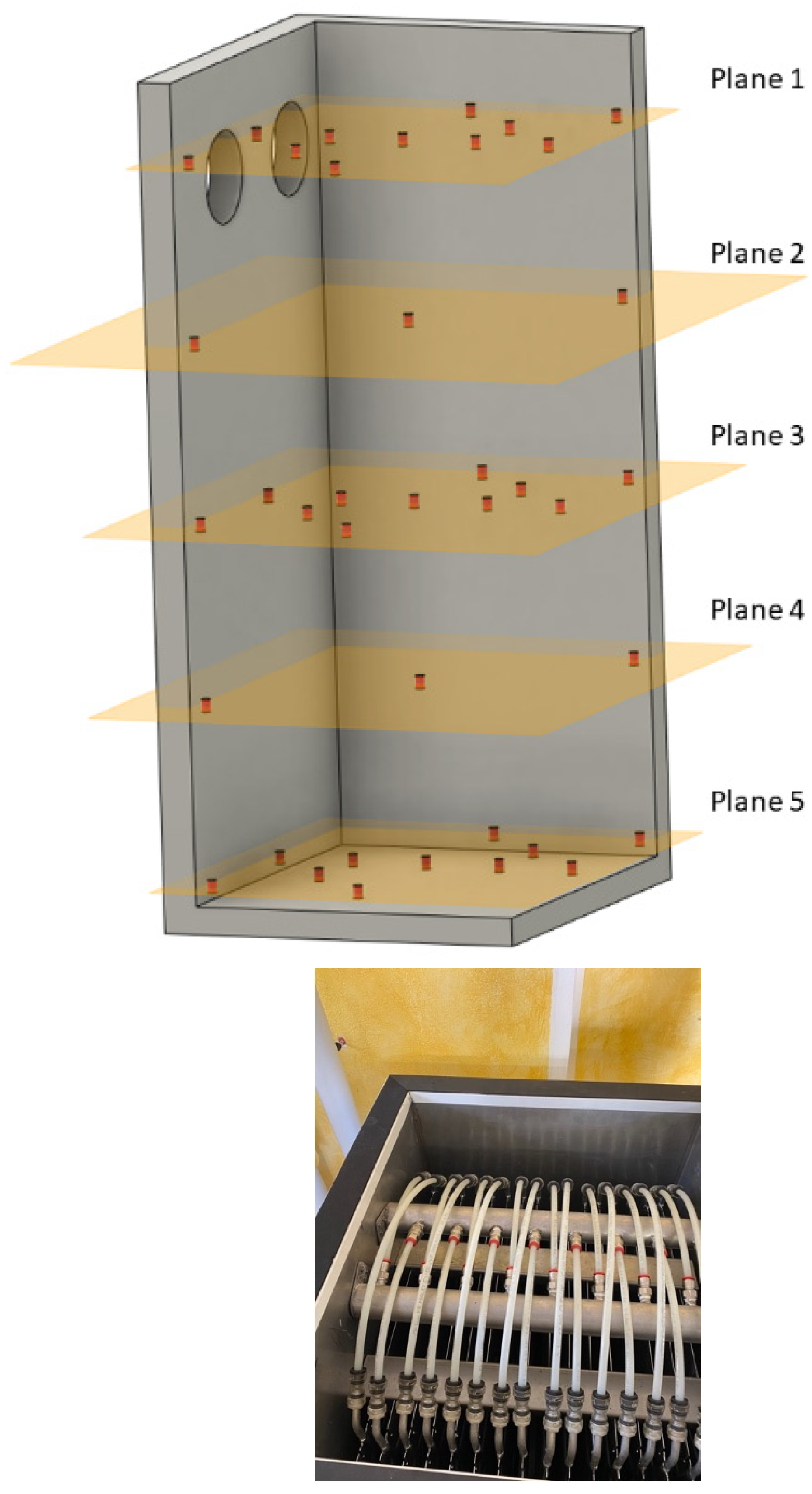
The LTES unit consists of a storage tank with internal dimensions of 1400 mm × 710 mm × 650 mm. The tank walls incorporate 50 mm of insulation to minimize heat losses, covered with an aluminum sheet. It contains 300 ± 0.5 kg of CRODATHERM9.5, a commercially available bio-based PCM supplied by CRODA.
This PCM has a phase change temperature peak at around 9 °C and a latent heat of 220 kJ/kg.
Table 1 reports the main thermophysical properties of the material.
Inside the tank, 16 aluminum roll bond heat exchangers (1170 mm × 570 mm × 1.5 mm) are installed and fed by chilled water. It is possible to see them in the picture reported in
Figure 2.
The total energy storage capacity of the system is approximately 18.7 kWh, comprising 17.5 kWh from the PCM latent heat, 1.1 kWh from the PCM sensible heat, and 0.1 kWh from the aluminum sensible heat.
To characterize the LTES performance, 39 thermocouples are purposefully placed across five vertical levels within the tank.
Figure 2 shows their positions and the overall system layout.
The LTES was placed in a climate chamber maintaining a constant ambient temperature of 20 °C within ±0.2 °C.
To complement the analysis of the tested system, a comparison between the bio-based PCM used in this study and two commercially available petrochemical-based PCMs is reported. These materials were selected for their similar melting temperature (approx. 8–10 °C) and commercial availability in thermal energy storage applications.
Table 2 reports the main thermal properties of CRODATHERM 9.5 (bio-based), Rubithetrm RT10 (paraffin-based), and Pluss OM08 (oleochemical-based), as stated in manufacturer datasheets and as measured in the study by [
34]. While petrochemical PCMs such as RT10 offer consistent thermal properties and low costs, bio-based PCMs are derived from renewable sources, have a lower environmental impact, and are often biodegradable. Nevertheless, some challenges persist regarding their long-term thermal stability and sensitivity to oxidation or microbial degradation.
Several studies have investigated the cycle stability of bio-based PCMs and compared it to paraffinic materials. For example, Quanying et al. [
35] reported that bio-based PCMs may exhibit an acceptable stability up to 300–500 cycles, although their degradation onset may be earlier than in paraffins depending on the encapsulation methods and environmental exposure.
Material compatibility is another critical aspect, especially for bio-based PCMs, which can be more reactive with metals or plastics used in storage enclosures. In their comprehensive review work, Adesousi et al. [
36] conducted a detailed compatibility study and highlighted potential risks of corrosion or polymer softening depending on the PCM formulation.
Despite these considerations, the use of bio-based PCMs remains attractive due to their renewable origin and favorable thermophysical properties [
37]. Their integration into commercial systems is increasingly feasible, especially when supported by appropriate stabilization techniques and compatibility assessments.
2.3. Data Reduction
Results are discussed in terms of the average temperature of the PCM inside the LTES, the energy absorbed by the LTES calculated as the integral of the instantaneous cooling capacity (P), which was calculated on the water side as the product between the water flow rate, specific heat, and temperature difference between the inlet and outlet of the tank, as measured by the high-precision T-type thermopile (Equation (1)).
As a consequence, the energy absorbed and released can be evaluated according to Equation (2), where
is the initial time and
is the ending time of the interval.
According to the Kline and McClintock [
38] method, the uncertainty of the total energy stored (
E) was evaluated to be maximum ±3.1% and on average ±1.5%.
2.4. Test Procedure
The same research group of the present paper fully characterized the LTES in a previous work by using two thermostatic baths to charge and discharge the system in order to understand the performance at a constant water inlet temperature and flow rate [
39].
In fact, the tests on the LTES system were carried out using a thermostatic bath to supply water at different set constant temperatures and different flow rates.
The charging process began from an ambient temperature of 20 °C and continued until all PCM thermocouples recorded a temperature below 7 °C (i.e., 2 °C below the declared freezing temperature).
Table 3 summarizes the experimental test conditions.
3. Experimental Results
LTES
Final users have very different energy demand profiles: some require a high power in a short time, others are satisfied with low power peaks lasting for a long time. To be able to serve different users, it is necessary to configure the storage in a dedicated way, making structural modifications to its geometry, such as increasing the quantity of metal inserts designed to increase the equivalent thermal conductivity. In this study, the geometry of the storage is fixed in order to ensure energy exchange profiles from the LHTES suitable to achieve the goal of the environmental thermal control of occupied spaces.
Through the analysis of energy charging patterns, it was demonstrated [
39] that a significant portion of energy is charged and discharged within the first 4 h due to the high temperature difference between the supply water and the average PCM temperature and a relatively low thermal resistance between the PCM and the roll bond. As far as the solidification proceeds, the thickness of the layer of the solidified PCM over the roll bond increases and, accordingly, the thermal resistance increases, thus reducing the energy exchange rate. For example, the energy stored during the sixth hour of continuous charging is about 20% of the energy stored during the first hour of charging. Hence, in the present test campaign the test duration was fixed to about 6 h max (360 min).
To modify this trend, enhanced heat transfer mechanisms could be considered, such as decreasing the pitch between roll bond plates or increasing the metal surface area in contact with the PCM. However, the current charge–discharge profile was deemed sufficient for applications not requiring high power peaks, such as maintaining a constant temperature in the built environment throughout the day.
In the previous work [
39], the working conditions for the present LTES were optimized, and it was observed that the maximum energy is accumulated when the roll bonds are supplied with water at 2 °C and a flow rate of 16 L/min, both with a continuous and intermittent supply, simulating different charging profiles. The stability of the water supply temperature to the TES guaranteed during the tests was ±0.2 K.
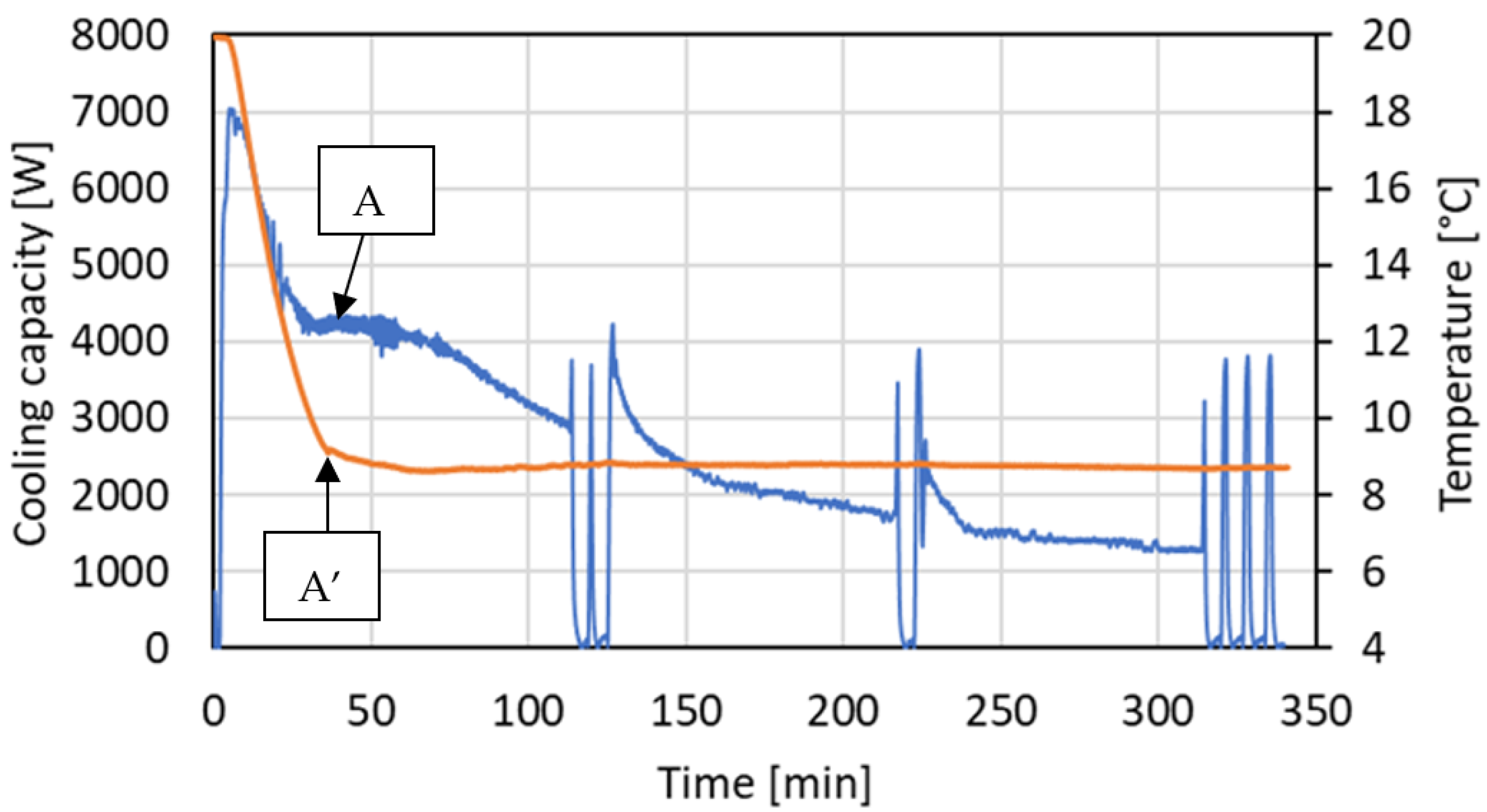
Figure 3 reports (orange line) the profile of the thermal power exchanged during the tests reported in the Righetti et al. [
39] work.
The exchanged thermal power decreases monotonically from a value of about 6 kW to 1 kW over a period of about 350 min.
Consequently, in the present work, it was decided to set the same values for the temperature and flow rate of the water supply to the LTES. For the construction of the HP/AC, a rotary compressor was chosen, capable of working under a variable speed control between 25 and 75 Hz with a nominal power at 50 Hz of approximately 5 kW when the chilled water production temperature is 2 °C at a condensation temperature of 25 °C (kept constant in all tests).
The variable rotation speed control of the compressor was set to maintain the water outlet temperature from the evaporator at 2 °C, and the return water temperature from the LTES to the evaporator was chosen as the control parameter. If the load required by the PCM decreases, the return water temperature decreases (as the supply temperature to the LTES is fixed). Therefore, the driver reduces the supply frequency (i.e., the rotation speed of the compressor) and with it the cooling capacity provided. The cooling capacity over time for the HP/AC is reported in blue in
Figure 3 and
Figure 4.
The cooling capacity profile obtained with the HP/AC (blue) is more scattered in comparison with the profile obtained when the thermostatic bath is used (orange). However, the difference in the stored energy (calculated with Equation (2)) is rather limited: 6.3% lower for the HP/AC system.
In
Figure 3, letters A, B, C, and D indicate the points of major difference between the blue profile (HP/AC) and the reference orange profile (thermostatic bath).
Table 4 summarizes the key points observed during the LTES charging with the HP/AC unit. The “knee” in point A corresponds to the onset of the liquid–solid phase change in most of the heat transfer surface. This can be explained by examining the average PCM temperature reported in
Figure 5, together with the cooling capacity profile (for reference). The average PCM temperature is calculated as the average of the readings of the 39 thermocouples distributed inside the tank. The test starts with the PCM in liquid phase at a uniform temperature of 20 °C. The liquid phase is then cooled (sensible heat transfer) till point A, where for the first time the average temperature of the PCM is below 9.5 °C, that is the nominal phase change temperature for the CRODA9.5 organic PCM. The analysis of the temperatures recorded in each single plane (see
Figure 2) in point A indicates that an initial stratification occurs, with lower zones cooling and beginning the phase change earlier than others, with a relevant subcooling in the lower plates that reaches a temperature about 2.5 K lower than the nominal phase change temperature (9.5 °C). This phenomenon was observed also in Righetti et al. [
39]. The topmost plane (closest to the surface) was the last to begin the phase change, likely due to its proximity to the ambient air. After about only 50 min (i.e., more than 20 min later than point A), the entire PCM was in phase change, and the significant temperature stratification was no longer observed.
However, the average PCM temperature is a reliable indicator of the solid–liquid phase change in the PCM that requires a sharp change also in the variable speed compressor control (point A in
Figure 4).
According to
Figure 4, at the start-up when the PCM is in the liquid phase and at a relatively high temperature, the heat transfer rate through the roll bonds and the PCM is relatively high and so is the cooling capacity demand. Hence, the compressor driver rises the frequency to the max (75 Hz). Then, in point A the compressor runs for several minutes close to the nominal frequency (50 Hz). As mentioned before, at 50 min most of the roll bond surface is covered by a thin layer of the solid PCM, and the heat transfer rate continuously reduces. Accordingly, the compressor driver reduces the frequency almost monotonically to 37 Hz in point B (
Figure 3). The progressive decrease in the heat transfer rate (cooling capacity) is only partially compensated by the reduction in the compressor speed, and the evaporation temperature tends to decrease down to 0.2 °C. Hence the anti-frost protection is activated, and the compressor stops. The circulation pump continues to run, and the water circulates in the roll bonds, increasing its temperature through the heat transfer with the PCM. This allows the compressor to operate safely with the frequency decreasing from about 55 Hz down to 28 Hz.
In point C the anti-frost protection activates again, and the operation is similar as in point B.
At the restart, the compressor drive decreases the frequency from 38 Hz down to 25 Hz, which is the minimum allowable frequency.
According to the cooling capacity orange reference profile obtained with the thermostatic bath in
Figure 3, at point D the cooling capacity demand of the LTES is lower than 1 kW. At 25 Hz, the cooling capacity of the HP/AC unit is 1 kW; hence, the only way to further reduce the cooling capacity is to operate in an on–off mode. In this case the compressor drive is no longer capable of properly managing such a low cooling demand, and several on–off cycles occur that are detrimental for the compressor operation and life, and, consequently, the system is finally shut-down after about 340 min.
In conclusion, these results highlight the complex interplay between the LTES and HP/AC systems. They emphasize the need for the careful sizing and integration/control of components to optimize performance, particularly in managing the HP/AC’s operation to avoid inefficient cycling and to maintain high COPs throughout the charging process.
4. Conclusions
A proper integration of thermal storage in the heating and air conditioning system is mandatory in order to achieve the goal of decarbonization in the HVAC sector. Latent thermal energy storage is a promising alternative to traditional sensible heat storage (like, for example, water tanks), unfortunately there is no guarantee that a heat pump/air conditioning (HP/AC) unit will function optimally when installed and coupled with a storage tank that was not considered during the design phase.
The ideal approach would be to size both the HP/AC unit and an integrated storage system simultaneously to optimize the overall system performance. Furthermore, different users/applications have different energy demand profiles, so the storage system should be tailored to meet the specific requirements of each user/application.
This study demonstrates that when the HP/AC unit’s main components (e.g., evaporator and compressor) are properly chosen, together with a suitable control strategy and with reference to the actual dynamic behavior of a given LTES system, it is possible to fully exploit the LTES energy storage capabilities.
The findings of this research highlight the critical need for precise system sizing and advanced control strategies to optimize the performance of integrated heat pump and LTES systems. This points towards the potential for significant efficiency improvements through sophisticated regulation techniques and possibly the use of variable-capacity heat pumps.
To improve the thermal performance of the LTES system, future work may explore several technical optimization paths. These include increasing the density of internal fins or using extended surfaces to enhance heat transfer, optimizing the packaging structure of the PCM to reduce thermal resistance, and employing high-conductivity additives or composite PCMs. Additionally, more advanced control strategies for the HP/AC unit could be implemented to better manage the part-load operation and minimize inefficient on–off cycling.
By adopting a more holistic approach to system design and implementation, we can unlock the full potential of LTES systems, leading to more efficient, sustainable, and user-specific heating and cooling solutions.


