Article

Novel Hybrid Islanding Detection Technique Based on Digital Lock-In Amplifier †

by
Muhammad Noman Ashraf
,
Abdul Shakoor Akram
and
Woojin Choi
*
School of Electrical Engineering, Soongsil University, Seoul 06978, Republic of Korea
*
Author to whom correspondence should be addressed.
This paper is an extended version of our paper published in Proceedings of the KIPE Summer Conference, Seoul, Republic of Korea, 2–4 July 2019; pp. 77–79.
Energies 2025, 18(13), 3449; https://doi.org/10.3390/en18133449
Submission received: 22 May 2025 / Revised: 27 June 2025 / Accepted: 28 June 2025 / Published: 30 June 2025
(This article belongs to the Special Issue Power Electronics and Power Quality 2025)

Abstract

Islanding detection remains a critical challenge for grid-connected distributed generation systems, as passive techniques suffer from inherent non-detection zones (NDZ), and active methods often degrade power quality. This paper introduces a hybrid detection strategy based on monitoring inherent grid harmonics via a Digital Lock-In Amplifier. By comparing real-time 5th and 7th harmonic amplitudes against their three-cycle-delayed values, the passive stage adaptively identifies potential islanding without fixed thresholds. Upon detecting significant relative variation, a brief injection of a non-characteristic 10th harmonic (limited to under 3% distortion for three line cycles) serves as active verification, ensuring robust discrimination between islanding and normal disturbances. Case studies demonstrate detection within 140 ms—faster than typical reclosing delays and well below the 2 s limit of IEEE std. 1547—while preserving current zero-crossings and enabling grid impedance estimation. The method’s resilience to grid disturbances and stiffness is validated through PSIM simulations and laboratory experiments, meeting IEEE 1547 and UL 1741 requirements. Comparative analysis shows superior accuracy and minimal power-quality impact relative to existing passive, active, and intelligent approaches.

1. Introduction

The development of distributed power generation systems (DPGSs) offers a cost-effective and efficient means of producing electricity close to the load or loads. Both local loads and excess electricity can be supplied to the grid by DPGS that integrate renewable energy sources such as solar, fuel cells, ESS, etc. [1]. There are several advantages of connecting DGPS to the conventional power system, including improved power quality, reduced power loss, network dependability, and environmental benefits. In addition to the previously mentioned benefits of connecting the DPGS to the grid, there are a few drawbacks, particularly with reverse power flow, which can result in issues such as voltage and frequency deviation, harmonics, power system dependability, and islanding.
The electrical phenomenon known as “islanding” in a DPGS occurs when the grid’s energy supply is disrupted by feeder switching, switch-gear operation, fault clearing operation, or, in certain situations, unplanned outages, etc., and DPGS continues to power the local loads. As a result, the power grid loses control over this remote area of the distribution system, creating an “island” that includes both local loads and generation. This could jeopardize security, service restoration, equipment dependability, worker safety, and power grid restoration [2]. Generators should thus cut off from the grid as quickly as possible in the event of an inadvertent island development when DPGS is present. A maximum delay of two seconds is required by IEEE std. 1547 for island detection, which must incorporate relay tripping time and islanding detection [3].

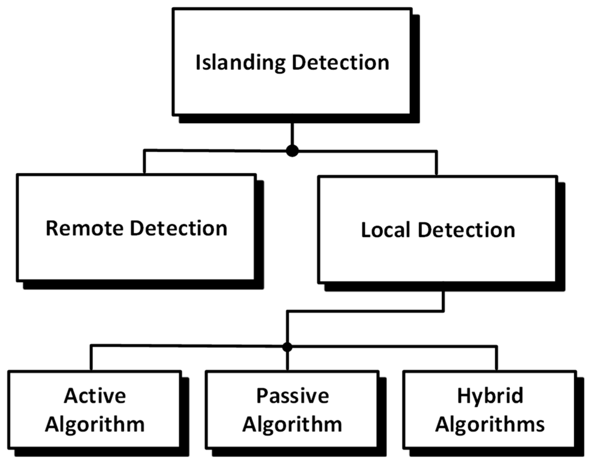
2. Islanding Detection Methods Review

Because islanding detection is so important, a lot of work has been published in the literature on the subject. As seen in Figure 1, islanding detection can be split into two primary categories: (1) remote detection and (2) local detection, which can be further divided into three types. Local islanding detection methods are generally classified as active, passive, or hybrid. Remote schemes rely on communication links between distributed power generation systems (DPGSs) and utility operators, but these approaches tend to be expensive, inflexible, and complex to implement. Examples include power line carrier communications [4,5] and SCADA-based solutions [6]. Inter-tripping methods detect breaker openings and signal-affected generators in the corresponding island zones [7], yet they require additional hardware at each DPGS, reducing cost-effectiveness. Therefore, local techniques—whether passive, active, or hybrid—are typically preferred for their lower implementation overhead and greater flexibility.
Grid-connected inverters’ system parameters, including voltage, frequency, phase, and others, are typically monitored by passive algorithms. An islanding event is deemed to have occurred, and DPGSs are removed from the grid when one or more of these parameters significantly deviate from the allowed limits. However, system parameter deviation is insufficient when the power discrepancy between DGPS and local loads is minimal. As a result, passive techniques suffer from the “non-detection zone” (NDZ) problem in low-power mismatch cases. The region (measured in terms of the power differential between the local loads and the DPGS inverter) where an islanding detection technique is unable to identify this circumstance is known as the NDZ [8]. Over-/undervoltage (OUV) and over-/underfrequency (OUF) monitoring are two basic passive algorithm techniques that can identify islanding [9,10]. OUV OUF, however, shows a substantial NDZ. The monitoring of the rate of change in frequency (ROCOF) [11], the rate of change in active power (ROCOAP), the rate of change in reactive power [12], phase jump detection (PJD) [13], the change in source impedance [14], voltage unbalance [15], and the total harmonic distortion technique of current [16] are also components of some extended passive techniques. However, it is acknowledged that the aforementioned methods have a significantly large NDZ because the degree of mismatch between local loads and DPGSs determines changes in the parameters under observation, such as voltage, phase, frequency, etc. Under nearly matched conditions, these techniques will not be able to detect islanding, putting the safety of the personnel and the distribution system as a whole at risk. In the literature, new studies on passive algorithms have also been proposed using extremely sophisticated methods such as neural networks, decision trees, and wavelet transform [17,18]. There are not many techniques that base their choices on monitoring several parameters, such as in [19], where variations in frequency and active power are examined concurrently. Additionally, islanding is detected in [20] by observing changes in the voltage imbalance and the current THD generated at the Point of Common Coupling (PCC). Combining passive methods with artificial intelligence is another recent development in islanding detection approaches, which has the benefit of high accuracy and dependability. For example, ref. [21] suggests using Parseval’s theorem and the discrete wavelet transforms (DWT) to extract features at various resolution levels. In order to retrieve the best threshold-setting information from a sizable data collection of system parameters, literature [22,23] suggested a data mining technique. In [24], a naïve-Bayer classifier was used to train the rotational invariance technique (ESPRIT), which estimates the signal parameters and detects islanding. However, the aforementioned methods of detecting islanding that use artificial intelligence or learning algorithms show increased computing cost and implementation complexity, rendering them unsuitable for low-end applications. The primary drawback of traditional passive techniques is a sizable non-detection zone (NDZ), where variations in voltage and frequency levels in specific areas of the real/reactive power plane are so minute that they cannot be detected.
Active islanding detection methods deliberately and carefully induce the disruption at the DPGSs’ output. Its foundation is the idea of disruption and observation. Voltage, frequency, and other factors are perturbed. Under normal grid-connected operation, the utility network provides a stable voltage and frequency reference, so the small perturbations introduced by active detection schemes have a negligible impact on overall power quality. When islanding occurs, when the grid is disconnected, these perturbations produce pronounced deviations in monitored parameters, triggering a trip signal. Active methods achieve this by injecting or modulating signals in the inverter output. For example, current injections add a small periodic disturbance to the inverter’s current output [25], while negative-sequence current or voltage injection introduces unbalanced components that become detectable only in the absence of the stiff grid reference [26,27]. High-frequency signal injection superimposes a signal at a frequency outside the normal spectrum to reveal impedance changes [28]. Virtual impedance techniques, such as virtual capacitors or inductors [29,30], modify the inverter’s output characteristics in a controlled way to provoke detectable responses under islanding. PLL perturbation methods slightly modulate the phase-locked loop reference to observe the system’s reaction [7], and voltage phase angle manipulation adjusts the reference angle of injected current to introduce changes noticeable only when disconnected from the grid [31]. Frequency or voltage shifting schemes—such as slip-mode frequency shift, Sandia frequency/voltage shifts, active frequency drift, and broader frequency schemes (e.g., GEFS) [32,33,34,35,36,37,38,39]—intentionally alter the inverter’s output frequency or voltage magnitude so that when the grid is present, its stiffness masks these shifts, but when islanding occurs, the deviations become clear.
By deliberately perturbing inverter output in these ways, active methods can substantially reduce or even eliminate the non-detection zone (NDZ) inherent to passive approaches since even small power mismatches produce observable responses. However, because they introduce deliberate perturbations, albeit brief or low in amplitude, they carry the risk of degrading power quality through increased harmonic distortion or voltage/frequency excursions and, if not carefully designed, may affect system stability. Consequently, proper filter design, minimal perturbation amplitudes, and strictly time-limited injection intervals are essential to balance NDZ reduction against the need to preserve power quality and ensure reliable operation.
This study introduces hybrid islanding detection, which combines the benefits of active and passive techniques. This is due to the broad NDZ of passive techniques and the continuous power degradation of active techniques. The suggested technique uses a digital lock-in amplifier to detect the fifth and seventh harmonics at the PCC in real time. A possible islanding condition is suspected when there is an aberrant variance in the harmonic amplitudes. This is confirmed by injecting non-characteristic harmonic perturbation for three-line cycles. The suggested method has no NDZ because the harmonic features are independent of the load conditions. Furthermore, only three line cycles are affected by the slight harmonic disruption; therefore, there is no degradation in the output power quality. The following are the main characteristics of the suggested islanding detection techniques: (1) The suggested method only requires grid angle information and PCC voltage feedback, and no additional hardware is needed. Furthermore, (2) it does not depend on the reference frame of the PLL or current controller, whether it be a stationary or synchronous frame. (3) Since the proposed technique just includes a multiplier and LPF, the control settings are simple to adjust. (4) Any nth-order harmonic can be calculated using the modified DLA harmonic extraction method. (5) The DLA is impervious to high-frequency noise, DC offset of any kind, and other measurement problems that may result from inaccurate feedback sensors. The suggested method’s operation will be thoroughly explained in the next section.

3. Harmonic Distribution in the Grid

Compact fluorescent lamps (CFLs), computers, televisions, switch-mode power supplies, transformers, and other non-linear electronic loads have become much more common in recent years. Harmonic currents are introduced into distribution systems by non-linear loads. Depending on the type of load and how it interacts with other system components, non-linear loads draw a current that is not sinusoidal [40], resulting in a complex current waveform. The harmonics at integer multiples of the fundamental frequency are displayed via Fourier series analysis of non-linear load current. Furthermore, the flux in the rotating machine’s air gap is irregular in motors and transformers, which results in the generation of non-sinusoidal waveforms. Additionally, the transformer’s magnetic circuits may saturate and produce harmonics. Harmonics are also produced when the transformer cores become saturated from operating at an unusually high voltage. Grid harmonics also rise as a result of industrial plants using capacitor banks for power factor correction. The network’s resonance circuits amplify the voltage harmonics as well, causing the grid voltage to become distorted.
According to field survey data on harmonics, distribution systems have 1–3% of total persistent harmonic content [18,41,42]. Numerous field tests and surveys have provided ample evidence of the existence of small ambient harmonics in a distribution network, both at the customer side and at the distribution substations. Of particular interest are low-order harmonics, such as the fifth and seventh harmonic content in both voltages and currents [19,20,43]. The grid voltage has odd and even harmonics up to the 25th order, but the 5th and 7th harmonics are the most prominent in terms of amplitude, according to numerous studies conducted in the lab with the aid of a spectrum analyzer. The suggested method depends on identifying islanding by using this ambient harmonic content, specifically the fifth and seventh harmonics. As will be further explained in the following section, a digital lock-in amplifier is used to determine the magnitude of the fifth and seventh harmonics.

4. Proposed Digital Lock-In Amplifier Anti-Islanding Detection

Although the anti-islanding technique suggested in this literature can be applied to microgrids and three-phase grid-connected systems, the effectiveness of the suggested approach is illustrated in this paper using the single-phase grid-connected system seen in Figure 2. Loads are parallel with the grid and inverter, and thus, the grid-connected inverter is by an LCL filter to PCC. The switch S is controlled by the inverter’s main control mobility; however, a trip signal needs to be generated in case of grid failure to isolate the switch, thereby preventing the formation of islands.

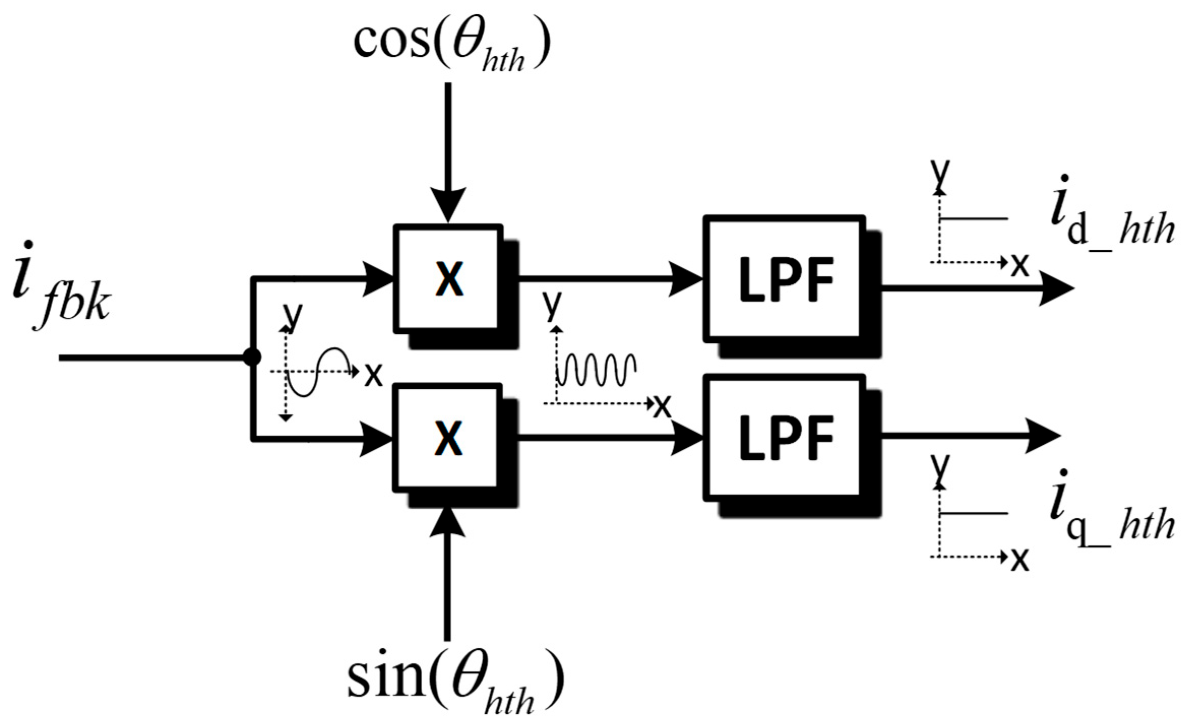
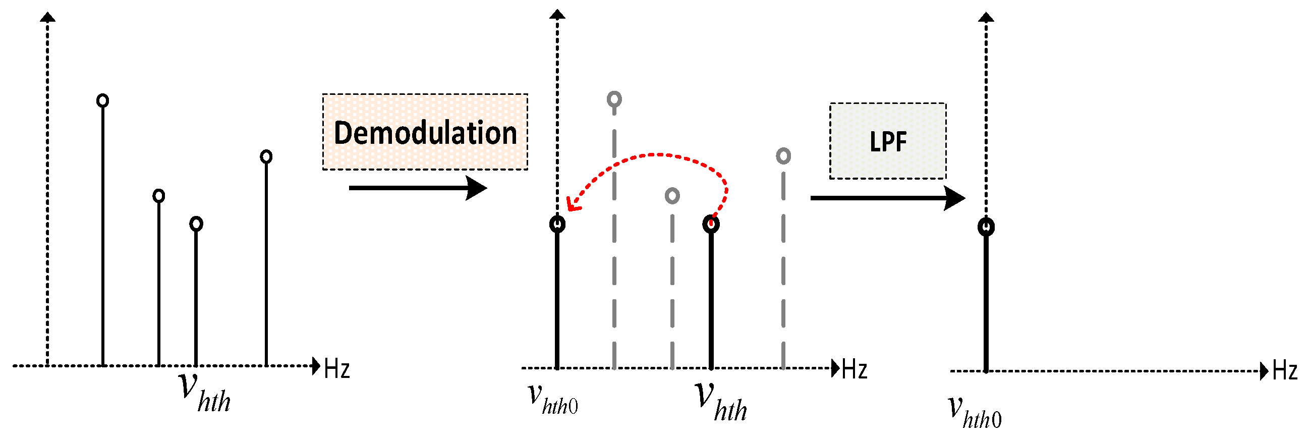
4.1. Digital Lock-In Working Principle

Phase-Sensitive Detectors (PSD), another name for Digital Lock-in Amplifiers (DLAs), are commonly employed in physical instrumentation to extract low-magnitude periodic signals that are obscured by random noise and other disturbances [21]. The PSDs are utilized as analog devices, and comprehensive evaluations of their use and a complete description of how they work can be found in [44,45].
Figure 3 shows the general structure of the DLA, DLA works on the principle of multiplying the input signal with the reference signal with a fixed frequency whose amplitude and phase information is required, multiplication of input signal yields the signal named as “Demodulator Outputs”. Reference signals are generated in Digital Signal Processor (DSP) with an arbitrary phase, this process of multiplying the sinusoidal reference signals with the input signal is also termed as Phase Sensitive Detection (PSD), down-modulation or down-mixing, lock-in amplification, lock-in detection, coherent detection and coherent demodulation in digital signal processing terms.
The outputs of the demodulators in the PSD have two characteristics: The amplitude and phase information of the wanted harmonic in the input signal is shifted or converted to a zero frequency or DC value when fixed frequency reference signals of pure sinusoids of the same phase are multiplied with the input signal. Further, any additional harmonics at the input signal, which can also be regarded as noise, are passed to the twice-the-spacing frequency component. As far as the key feature of the PSD is the possibility to switch between frequencies, the DLA is better than other workable harmonic isolation approaches, which are based on bandpass filters, notch filters, etc.
As depicted in Figure 4, multiple harmonics can be found in the FFT of a random signal. Nevertheless, the intended hth harmonic is transferred to zero frequency following demodulation, and other harmonics are eliminated following low-pass filtering. With a bandwidth of 0.01 Hz, PSD may identify the amplitude and phase information of the signal of interest [43]. With the aforementioned filters, however, a bandpass filter with such a small bandwidth cannot be designed.
This so-called bandwidth narrowing is the major benefit a digital lock-in amplifier brings. The only inputs that translate to output are those at reference frequency since, in these cases, the zero-frequency component is present. The property of frequency shift of PSD is explained with the help of the next mathematical expressions.
V g r i d = v p cos ω g t + θ g + v 3 h cos 3 ω g t + 3 θ g + + v n h cos n ω g t + n θ g
The grid voltage’s characteristic equation, which includes odd harmonics up to nth order, is displayed in (1). On the other hand, vnh stands for the nth harmonic peak amplitude. The grid phase angle is represented by θg.
v h t h _ r e f = cos h ω R E F t + h θ R E F v h t h _ r e f = sin h ω R E F t + h θ R E F
In order to get the harmonic amplitude information, two 90-degree phase-shifted reference signals are multiplied with the grid feedback signal. The relation for the reference signal is shown in (2). Reference signals are generated with the help of the PLL output phase angle, i.e., θg.
v x h t h = v g r i d v h t h _ r e f 1 v g r i d cos h ω P L L t + h θ P L L v y h t h = v g r i d v h t h _ r e f 2 v g r i d sin h ω P L L t + h θ P L L
(3) shows the demodulator outputs, where the reference signal is multiplied with vgrid to get the vx and vy. In order to get the final peak amplitude information of any harmonic present in the grid, (4) shows the final output relation of the DLA output.
v h t h = v x h t h 2 + v y h t h 2
In order to explain the harmonic extraction of the PSD, (3) will be further solved with the help of trigonometric products to sum identities shown in (4) and (5).
sin ( α ) cos ( β ) = 1 2 cos ( α β ) cos ( α + β )
cos ( α ) cos ( β ) = 1 2 cos ( α β ) + cos ( α + β )
The above identities show that whenever the two sinusoids having phase angles α and β are multiplied together, the resulting output contains the sum of two signals having phase angle, (αβ) and (α + β). It corresponds to the output signal having two frequencies, i.e., (f − fref) and (f + fref).
v x h t h = cos ( h + 1 ) ( ω o t + θ o ) + cos ( h 1 ) ( ω o t + θ o ) + v 3 h cos ( h + 1 ) ( 3 ω o t + 3 θ o ) + cos ( h 1 ) ( 3 ω o t + 3 θ o ) + v 5 h cos ( h + 1 ) ( 5 ω o t + 5 θ o ) + cos ( h + 1 ) ( 5 ω o t + 5 θ o ) + v n h cos n + h ω o t + n + h θ o + cos n h ω o t + n h θ o
Equations (7) and (8) show the relation for the demodulator outputs, where it can be realized that the fundamental, 3rd, 5th, and nth harmonics, after multiplication with the reference, are shifted to their corresponding (f − fref) and (f + fref) frequencies. However, the harmonic with a frequency equal to the frequency of the reference signal will have (f − fref) equal to zero and (f + fref) equal to double the harmonic frequency. However, the only useful information from the demodulator outputs is the zero-frequency component, also called the DC component; all other double-frequency components are filtered out using the low-pass filter (LPF) with adequate cutoff frequency.
v y h t h = sin ( h + 1 ) ( ω o t + θ o ) + sin ( h 1 ) ( ω o t + θ o ) + v 3 h sin ( h + 1 ) ( 3 ω o t + 3 θ o ) + sin ( h 1 ) ( 3 ω o t + 3 θ o ) + v 5 h sin ( h + 1 ) ( 5 ω o t + 5 θ o ) + sin ( h 1 ) ( 5 ω o t + 5 θ o ) + v n h sin n + h ω o t + n + h θ o + sin n h ω o t + n h θ o
v x _ h t h = v n h 2 cos ( h ω R E F h ω g ) t + ( h θ R E F h θ g )
v y _ h t h = v n h 2 sin ( h ω R E F h ω g ) t + ( h θ R E F h θ g )
Equations (7) and (8) show the output after the LPF, where the residual AC ripple is removed. Only the component at zero frequency has remained, i.e., hf1 − hf2’.
sin 2 ( θ ) + cos 2 ( θ ) = 1
Using the Pythagorean theorem as revealed in Equation (9), we find the solution of Equation (11) to also have the amplitude information of definite hth harmonic.
A h t h = k n h 2 2 cos ( h ω R E F h ω g ) t + ( h θ R E F h θ g ) 2 + sin ( h ω P L L h ω g ) t + ( h θ P L L h θ g ) 2
Equation (12) is finally used for the amplitude extraction of the hth harmonic. Where the term containing the sine and cosine will vanish according to the theorem explained in Equation (9).
As shown in Figure 5a, the grid contains the odd harmonics, i.e., 3rd, 5th, 7th, etc. Figure 5b shows the output of the Digital Lock-In amplifier in which an amplitude of the 7th harmonic is calculated. It can be realized that the amplitude of the 7th harmonic shown in the FFT in Figure 5c is the same as calculated with the DLA. With less computational burden as well.

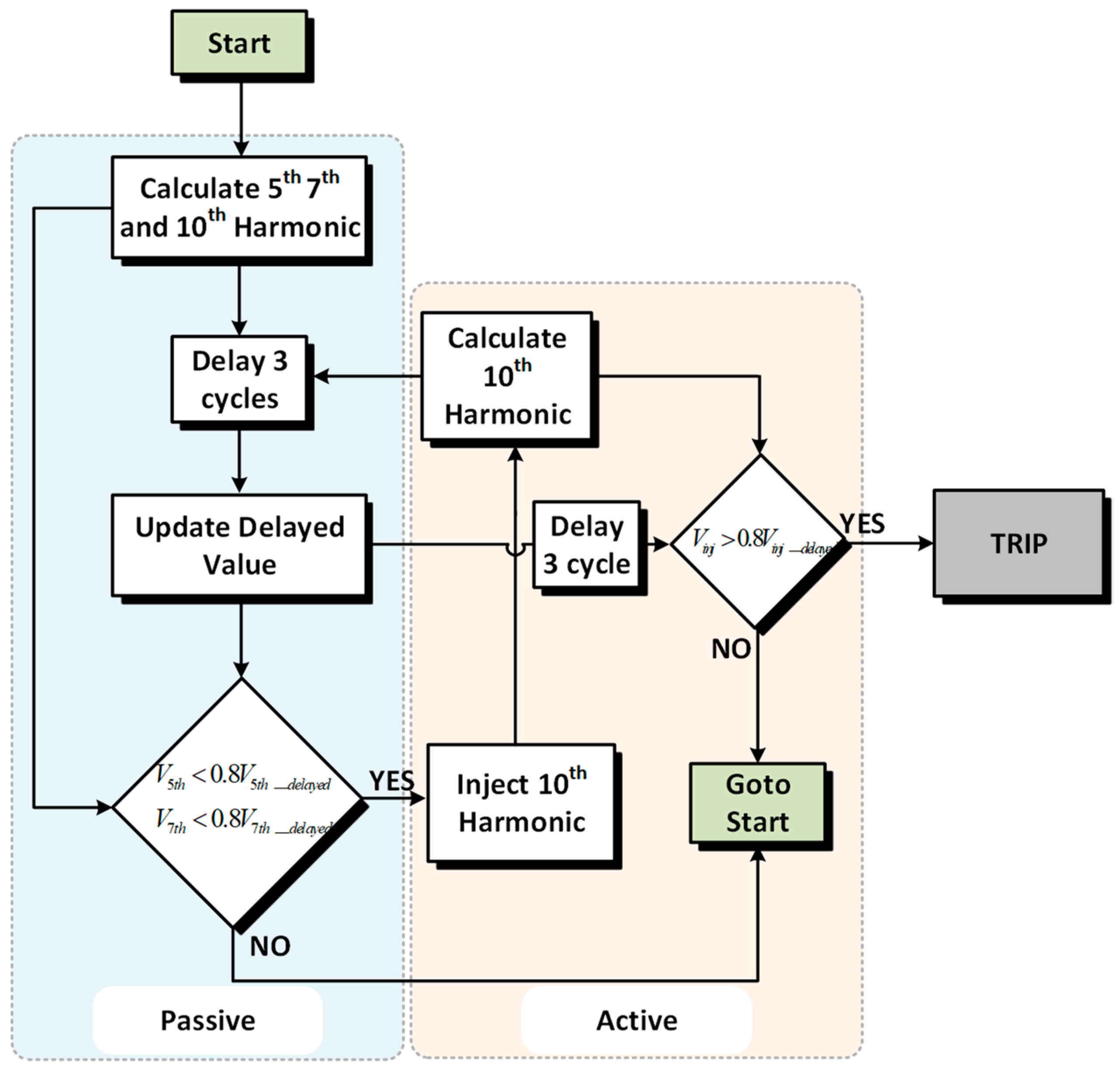
4.2. Passive Detection

The suggested islanding detection technique is a hybrid approach, as was described in the previous section. The first component of the suggested algorithm is a passive algorithm that tracks the fifth and seventh harmonics, or grid ambient harmonics, in real time.
During the normal operation of grid-connected inverters, the ambient harmonics present in the grid are unaffected, and voltage at PCC contains harmonics. Regardless of the harmonics in the grid, the inverter’s injected current is sinusoidal due to the under 5% boundary defined by IEEE std. 1547. The impedance difference brought on by grid disconnection causes the harmonics existing at PCC to either overshoot or undershoot. This overshoot or undershoot of the 5th and 7th harmonic is monitored in real time by using the DLA.
Since then, it has been known that the magnitude of harmonics undergoes a slight change depending on the time of day. Given the fact that, during the working hour, more non-linear loads are connected to grids. Hence, the amplitude of the harmonics is greater as compared with time after evening. Harmonic distribution was tested in the laboratory spectrum analyzer over the duration of 100 days at different times of the day. It shows the amplitude of the different harmonics, i.e., 3rd, 5th, and 7th, at different times of the day. Moreover, non-linear loads, switching capacitor banks, and other factors also add to the cause of varying harmonics. Therefore, rather than comparing the harmonic values with predefined threshold values, the overshoot or undershoot in harmonics is evaluated in order to detect the condition of possible island formation.
The sequence of the suggested Islanding detection algorithm Is shown In Figure 6. As can be seen, the passive part of the algorithm is the one that measures the fifth and the seventh harmonics in real time. Also, a real-time current sample of the 5th and 7th harmonics is equated with a three-line cycle-delayed value. When the present harmonic sample has an overshoot/undershoot that is greater than or less than 140 percent/60 percent when compared with the three-line cycle delayed value. These overshoot thresholds are optimized after consideration of a series of hundred tests performed at different times of the day.
v n t h ( n ) < 0.6 v n t h ( n 3 ) v n t h ( n ) > 1.4 v n t h ( n 3 )
The criterion for possible island development is shown in Equation (13) and is applicable to both the 5th and 7th harmonics. Active detection is activated to confirm the islanding state if any of them exhibit this behavior. The active perturbation injection will be explained in the following subsection.

4.3. Active Detection

The suggested approach uses active harmonic injection to confirm the possible island development, as seen in Figure 6. The method proposed is a simple, non-invasive, active anti-islanding technique comprising a specific active algorithm applicable to grid-connected inverter systems. The technique relies on phase angle, which is acquired through a PLL format using an orthogonal signal generator (OSG) PLL based on a second-order generalized integrator (SOGI) [21]. This output current that contains a tenth harmonic component is fed into the grid through the inverter of the DG. The injected tenth harmonic’s harmonic distortion factor (hdf) is maintained below 3%. Since the tenth harmonic is higher even order and non-characteristic, it is chosen for active detection in the suggested strategy. It is typically absent from the grid. As a result, it is simple to identify and differentiate from other harmonics. As depicted in Figure 7, perturbation is added in the final phase angle for the current controller. The magnitude of the perturbation is dependent on the coefficient λ, and k is the order of the harmonic.
cos ( θ ) I N V = cos ( θ P L L ) + λ I N J cos ( k θ P L L )
Equation (14) shows the final reference signal used by the current controller. Where θPLL is the fundamental phase angle estimated by SOGI PLL, moreover λINJ is the perturbation coefficient, i.e., the amplitude of the harmonic being injected.
v 10 t h ( n ) > 1.4 v 10 t h ( n 3 )
Tenth harmonic perturbation injection is done in only three cycles, with the overall trajectory being monitored by means of the DLA in an effort to prevent the further power quality decline of the grid-connected inverter. Equation (15) shows the condition of the formation of the trip signal. In that case, a trip signal will be triggered, and the inverter will stop feeding the grid in the event of the magnitude of the tenth harmonic exceeding the 40% overshoot value.

4.4. LPF Filter Design

Information about frequencies other than the reference frequency is shifted to their corresponding second harmonics, as was covered in the preceding subsection. The low-pass filter (LPF) must be used to eliminate any remaining AC ripple in order to obtain the desired harmonic phase and amplitude. The averaging that eliminates the products of reference with components at all other frequencies is provided by the low-pass filter that comes after the multiplier. Consequently, it is necessary to use LPF with the best cutoff and order. The attenuation of residual AC ripple is dependent on the roll-off and low-pass filter bandwidth. Noise sources that are very near the reference frequency will be eliminated by a small bandwidth; these signals can flow across a broader bandwidth. The bandwidth of detection is determined by the bandwidth of the low-pass filter. The low-pass filter will not alter the signal at the reference frequency, which is the only one that will produce a pure DC output.
G L P F ( s ) = ω c s + ω c k
(6) shows the relation of general LPF, where “k” shows the order of the LPF and “ωc” is the cutoff frequency of the employed LPF. To get pure amplitude and phase DC values of desired harmonic components, the LPF order and its cutoff frequency need to be selected carefully. For the design of the LPF, we must know the dominant and lowest frequency subharmonic components.
In the DLA, after the multiplication of the current with the reference signals the most dominant and lowest frequency sub harmonic is 120 Hz. Once we attenuate 120 Hz ripple, the remaining sub harmonics will certainly be attenuated by LPF. In the proposed technique, the order of LPF is 4th order with the cut off frequency of 10 Hz for hth harmonic attenuation is used.

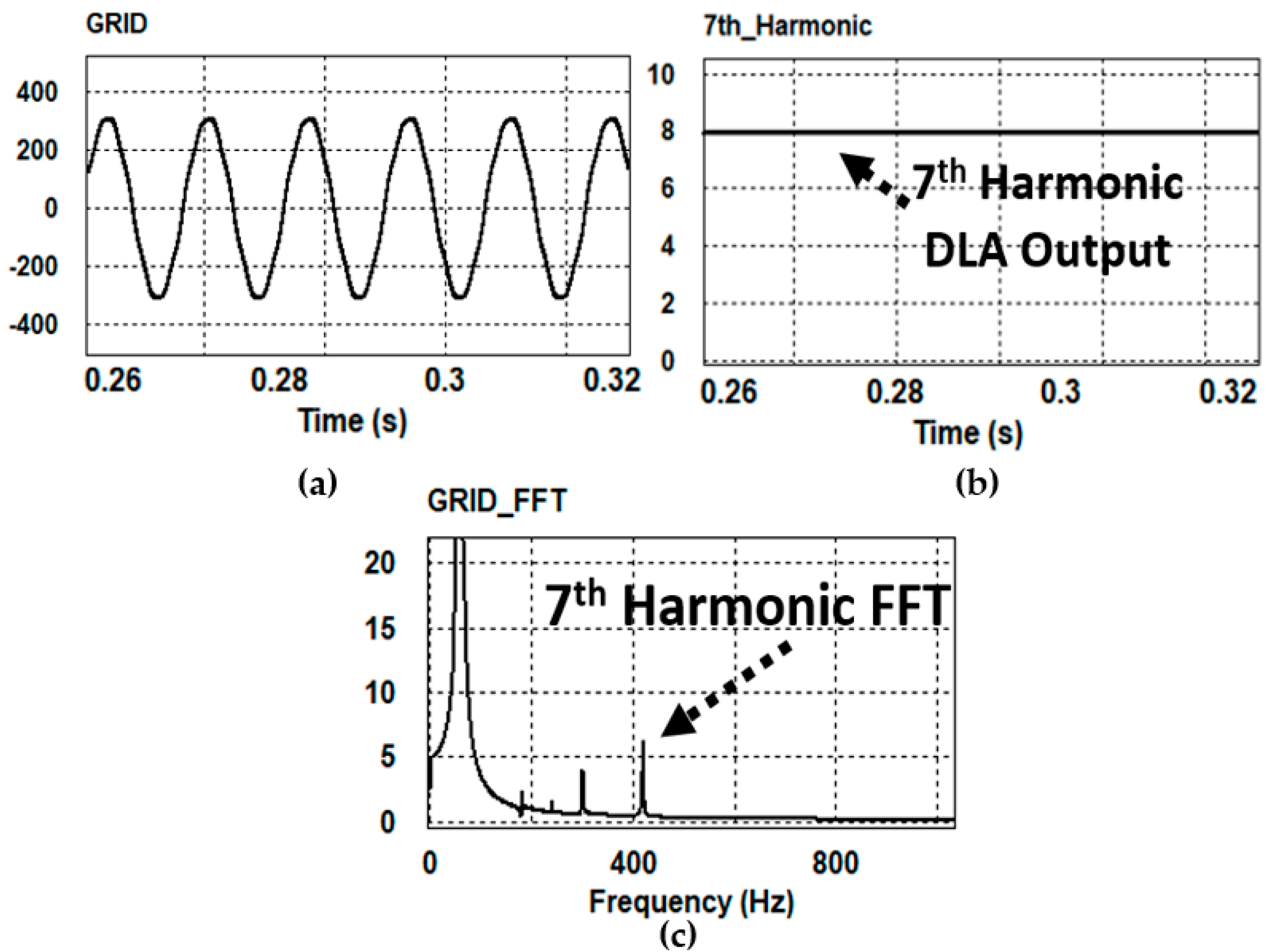
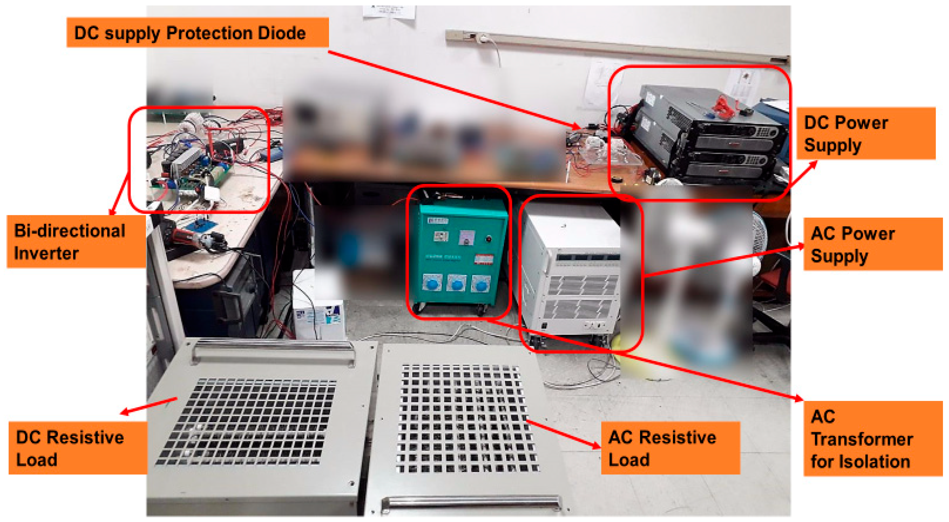
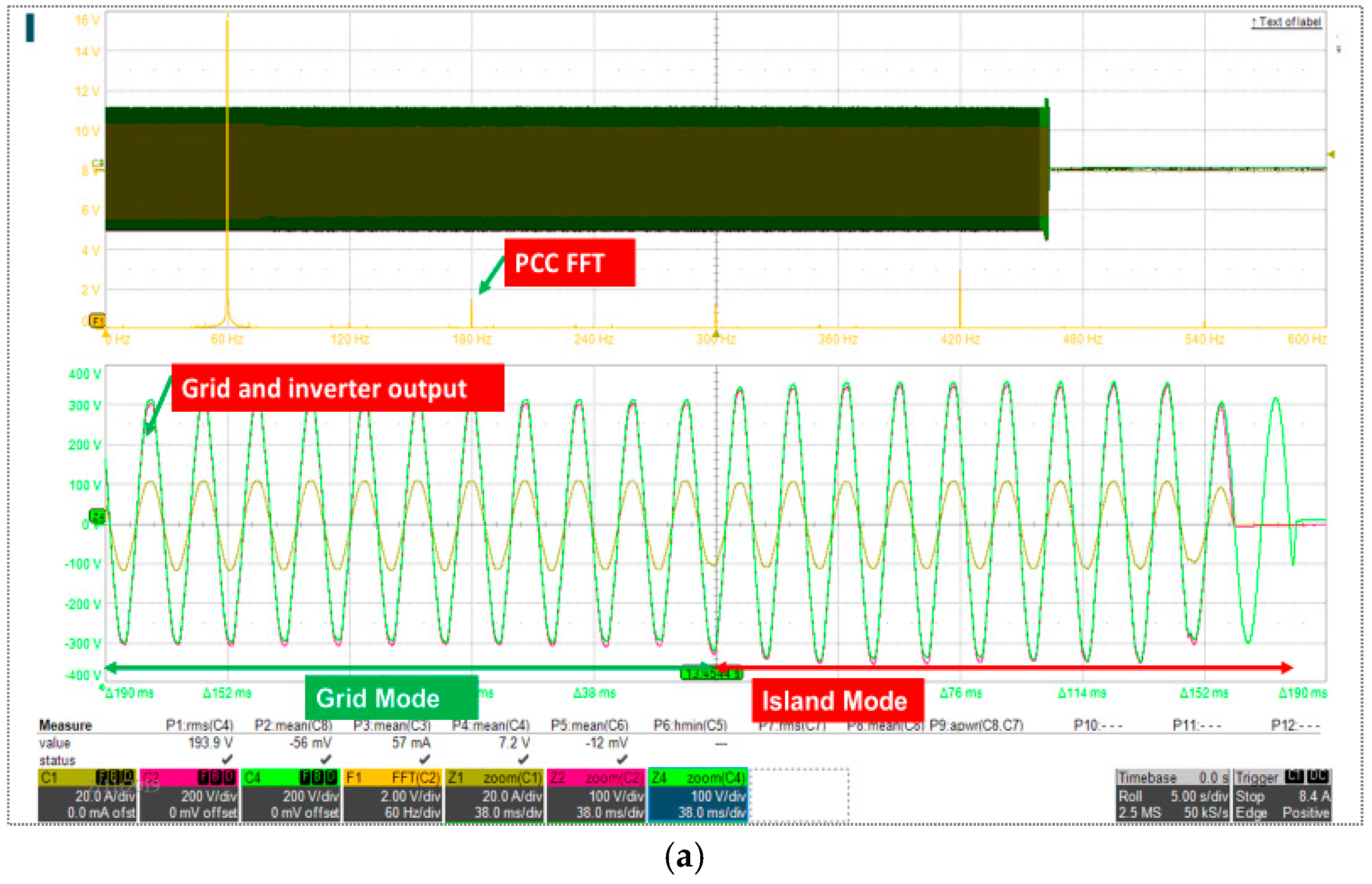
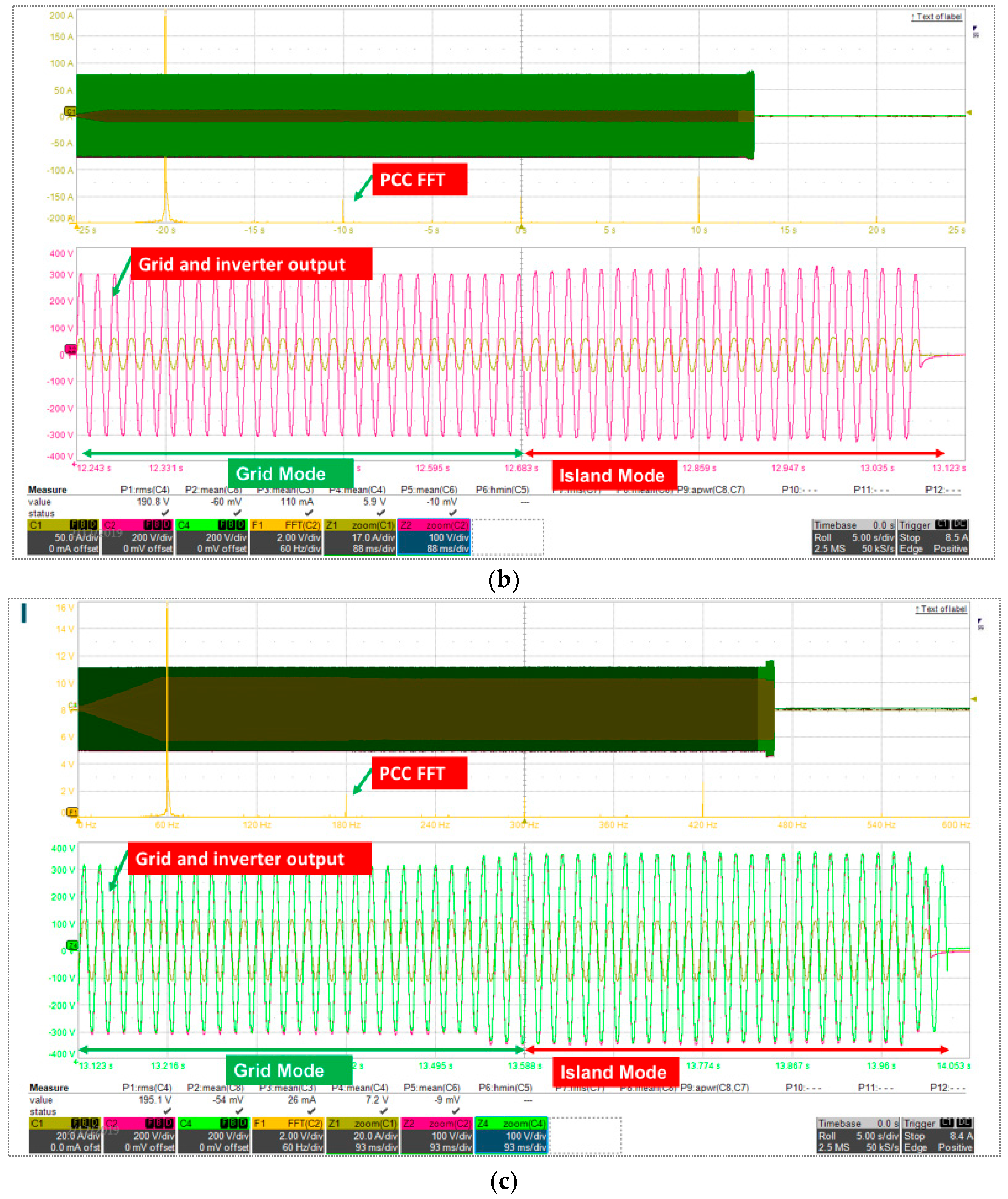
5. Simulation Results

The performance of the suggested islanding detection approach is assessed using PSIM simulations under various load scenarios, as illustrated in Figure 8. Similar harmonics with corresponding amplitudes are introduced to the simulation once the real grid’s harmonics are first measured using a spectrum analyzer. The voltage harmonics detected by the real grid are as follows: 2nd = 150 mV, 3rd = 2.6 V, 5th = 4.5 V, and 7th = 8.3 V. The suggested approach is tested under various load situations as the rated power of the inverter under test, even though harmonics are unaffected by local loads linked to grid-connected inverters.
Table 1 shows the detailed specifications of the system under test.
The suggested islanding detection approach is simulated in Figure 8, where the grid is disconnected at 0.2 s, and the inverter operates in grid-connected mode from 0 to 0.2 s. As shown in Figure DLA, it monitors the magnitude of harmonics in real time. Under normal operation, the harmonics at the PCC are constant. As soon as the grid is disconnected, the harmonics start to reduce. When it undergoes a change of more than 40%, islanding is suspected; therefore, the potential island signal becomes high. For verification of the suspected island, the 10th harmonic is injected. The DLA monitors the injected harmonic and generates the trip signal when harmonic amplitude increases greater than the threshold recommended by IEEE std. 1547, i.e., 33%, 66%, and 100% of the experimental results.
The necessary experiments have been conducted in order to validate the suggested islanding detection method; the whole hardware configuration is displayed in Figure 9. The control system was applied to a 5 kW inverter developed using a Texas Instruments TMS320F28335 digital signal processor (DSP) in hardware implementation (Dallas, TX, USA). The single-phase outputs were connected to the loads, and a direct connection between a DC source and the DC link was made. At a frequency of 10 kHz, the switching technique was unipolar. The main waveforms for islanding detection are displayed in Figure 10. VPCC and VGRID are the same during regular grid operation; however, as the figure illustrates, when the grid is unplugged, impedance changes cause the voltage at PCC to become pure sinusoidal. As a result, harmonics at PCC also drop. To confirm the possible islanding development, the inverter begins injecting the 10th-order harmonic after the four-line cycles when the active algorithm is activated.
The proposed method is tested under different load conditions, i.e., 33%, 66%, and 100%, at different times of the day. As mentioned in previous sections, harmonic distribution in the grid changes differently at different times of the day. Therefore, the proposed method was tested in the morning, afternoon, evening, and midnight. A total of 100 tests were carried out over the period of three weeks. Overall, the average total time taken by the proposed islanding method is found to be less than 140 mS, which is way under the time limit defined by IEEE std. 1547. During the tests, the accuracy of the proposed method was found to be 100%. The comparison table between the suggested approach and islanding detection methods from the most recent literature is displayed in Table 2. Although resilience, reliability, and accuracy are attained at the expense of longer detection times, the table unequivocally demonstrates that the accuracy of the suggested approach is higher than that of conventional methods. Only Reference [45] demonstrates 100% accuracy in comparison to the suggested method; however, due to the employment of sophisticated artificial intelligence techniques, it also has a larger learning time and a higher computing burden.

6. Conclusions

This work presents a simple, affordable, precise, and efficient hybrid approach to identify an islanding scenario for DPGS and grid-connected applications. The given landing detection concepts and methodologies are resilient and accurate, allowing them to identify faults in the AC grid network with minimal influence on the quality of renewable electricity exported to grids during regular operations. The proposed DLA-based hybrid islanding detection method contains both good points of active and passive islanding techniques. In the passive part of the algorithm, grid ambient harmonics are monitored to detect potential island formation. Under the grid fault condition, voltages at PCC undergo the overshoot or undershoot in the harmonics. In order to verify the potential island formation is due to the grid fault and not because of some motor operation or capacitor bank switching, the 10th harmonic is injected by introducing the perturbation in the inverter current reference, i.e., the PLL phase angle. More than 100 tests under various load scenarios and times of day have been carried out to validate the suggested approach. Alternative grids’ unique features may indicate that alternative harmonic components, like the ninth, eleventh, or thirteenth, should be used for detection. The IEEE std. 1547 standards were met by the suggested hybrid islanding detection approach, which successfully unplugged the grid-connected inverter under inadvertent islanding situations in less than two seconds.
Harmonic distribution is independent of loads connected to the inverter; therefore, the proposed method does not have any NDZ. Moreover, it does not have a continued detrimental effect on the power quality and stability of grid-connected inverters. These features make the proposed method suitable for islanding detection for grid-connected applications such as single-phase or three-phase inverters.

Author Contributions

Conceptualization, M.N.A. and W.C.; Methodology, M.N.A.; Software, M.N.A.; Validation, M.N.A.; Formal analysis, M.N.A., A.S.A. and W.C.; Investigation, A.S.A. and W.C.; Writing—original draft, A.S.A.; Writing—review & editing, A.S.A.; Supervision, W.C.; Project administration, W.C. All authors have read and agreed to the published version of the manuscript.

Funding

This research received no external funding.

Data Availability Statement

Data can be made available on the request statement.

Conflicts of Interest

The authors declare no conflicts of interest.

References

  1. Ropp, M.E.; Aaker, K.; Haigh, J.; Sabbah, N. Using Power Line Carrier Communications to Prevent Islanding. In Proceedings of the 28th IEEE Photovoltaic Specialist Conference, Anchorage, AK, USA, 15–22 September 2000; pp. 1675–1678. [Google Scholar]
  2. Ashraf, M.N.; Choi, W. A Novel Hybrid Islanding Detection Method Using Digital Lock-In Amplifier. In Proceedings of the KIPE Conference; The Korean Institute of Power Electronics: Seoul, Republic of Korea, 2019; pp. 77–79. [Google Scholar]
  3. Balaguer-Álvarez, I.; Ortiz-Rivera, E. Survey of distributed generation islanding detection methods. IEEE Latin Am. Trans. 2010, 8, 565–570. [Google Scholar] [CrossRef]
  4. Chowdhury, S.; Chowdhury, S.; Crossley, P. Islanding protection of active distribution networks with renewable distributed generators: A comprehensive survey. Electr. Power Syst. Res. 2009, 79, 984–992. [Google Scholar] [CrossRef]
  5. Mango, F.D.; Liserre, M.; Aquila, A.D.; Pigazo, A. Overview of anti-islanding algorithms for PV systems. Part I: Passive methods. In Proceedings of the 12th International Conference Power Electron. Motion Control EPE-PEMC, Portoroz, Slovenia, 30 August–1 September 2006; pp. 1878–1883. [Google Scholar]
  6. Zeineldin, H.H.; El-Saadany, E.F.; Salama, M.M.A. Islanding detection of inverter-based distributed generation. Proc. Inst. Elect. Eng.-Gener. Transm. Distrib. 2006, 153, 644–652. [Google Scholar] [CrossRef]
  7. Ye, Z.; Kolwalkar, A.; Zhang, Y.; Du, P.; Walling, R. Evaluation of anti-islanding schemes based on non-detection zone concept. IEEE Trans. Power Electron. 2004, 19, 1171–1176. [Google Scholar] [CrossRef]
  8. Freitas, W.; Xu, W.; Affonso, C.M.; Huang, Z. Comparative analysis between ROCOF and vector surge relays for distributed generation applications. IEEE Trans. Power Deliv. 2005, 20, 1315–1324. [Google Scholar] [CrossRef]
  9. Redfern, M.A.; Usta, O.; Fielding, G. Protection against loss of utility grid supply for a dispersed storage and generation unit. IEEE Trans. Power Deliv. 1993, 8, 948–954. [Google Scholar] [CrossRef]
  10. Yin, J.; Chang, L.; Diduch, C. A new adaptive logic phase shift algorithm for anti-islanding protections in inverter-based DG systems. In Proceedings of the Power Electronics Specialists Conference, Dresden, Germany, 16 June 2005; pp. 2482–2486. [Google Scholar]
  11. O’Kane, P.; Fox, B. Loss of mains detection for embedded generation by system impedance monitoring. In Proceedings of the Sixth International Conference on Developments in Power System Protection, Nottingham, UK, 25–27 March 1997; pp. 95–98. [Google Scholar]
  12. Ebadollah, K.; Javad, S. Islanding detection method for photovoltaic distributed generation based on voltage drifting. IET Gener. Transm. Distrib. 2013, 7, 584–592. [Google Scholar]
  13. Jang, S.; Kim, K. An islanding detection method for distributed generation using voltage unbalance and total harmonic distortion of current. IEEE Trans. Power Deliv. 2004, 19, 745–752. [Google Scholar] [CrossRef]
  14. Lidula, N.; Perera, N.; Rajapakse, A. Investigation of a fast islanding detection methodology using transient signals. In Proceedings of the IEEE Power Energy Society General Meeting, Calgary, AB, Canada, 26–30 July 2009; pp. 1–6. [Google Scholar]
  15. Sun, R.; Wu, Z.; Centeno, V. Power system islanding detection and identification using topology approach and decision tree. In Proceedings of the IEEE Power Energy Society General Meeting, Detroit, MI, USA, 24–28 July 2011; pp. 1–6. [Google Scholar]
  16. Abdolrasol, M.; Mekhilef, S. Hybrid anti-islanding algorithm for utility interconnection of distributed generation. In Proceedings of the International Conference for Technical Postgraduates, Kuala Lumpur, Malaysia, 14–15 December 2009; pp. 1–5. [Google Scholar]
  17. Karegar, H.; Shatace, A. Islanding detection of wind farms by THD. In Proceedings of the 3rd International Conference on Electric Utility Deregulation and Restructuring and Power Technologies, Nanjing, China, 6–9 April 2008; pp. 2793–2797. [Google Scholar]
  18. Gaing, Z.-L. Wavelet-based neural network for power disturbance recognition and classification. IEEE Trans. Power Del. 2004, 19, 1560–1568. [Google Scholar] [CrossRef]
  19. El-Arroudi, K.; Joós, G. Data mining approach to threshold settings of islanding relays in distributed generation. IEEE Trans. Power Syst. 2007, 22, 1112–1119. [Google Scholar] [CrossRef]
  20. El-Arroudi, K.; Joós, G.; Kamwa, I.; McGillis, D.T. Intelligent-based approach to islanding detection in distributed generation. IEEE Trans. Power Del. 2007, 22, 828–835. [Google Scholar] [CrossRef]
  21. Najy, W.K.A.; Zeineldin, H.H.; Alaboudy, A.H.K.; Woon, W.L. A Bayesian passive islanding detection method for inverter-based distributed generation using ESPRIT. IEEE Trans. Power Del. 2011, 26, 2687–2696. [Google Scholar] [CrossRef]
  22. Liu, F.; Kang, Y.; Zhang, Y.; Duan, S.; Lin, X. Improved SMS islanding detection method for grid-connected converters. IET Renew. Power Gener. 2010, 4, 36–42. [Google Scholar] [CrossRef]
  23. Zeineldin, H.H.; Conti, S. Sandia frequency shift parameter selection for multi-inverter systems to eliminate non-detection zone. IET Renew. Power Gener. 2011, 5, 175–183. [Google Scholar] [CrossRef]
  24. Stevens, J.W., III; Bonn, R.H.; Ginn, J.W.; Gonzalez, S.; Kern, G. Development and Testing of an Approach to Anti-Islanding in Utility Interconnected Photovoltaic Systems; Sandia National Laboratories Report SAND2000-1939; Sandia National Lab.(SNL-NM): Albuquerque, NM, USA, 2000. [Google Scholar]
  25. Chiang, W.-J.; Jou, H.-L.; Wu, J.-C. Active islanding detection method for inverter-based distribution generation power system. Int. J. Electr. Power Energy Syst. 2012, 42, 158–166. [Google Scholar] [CrossRef]
  26. Jou, H.-L.; Chiang, W.-J.; Wu, J.-C. Virtual inductor-based islanding detection method for grid-connected power inverter of distributed power generation system. IET Renew. Power Gener. 2007, 1, 175–181. [Google Scholar] [CrossRef]
  27. Velasco, D.; Trujillo, C.; Garcera, G.; Figueres, E. An active anti-islanding method based on phase-PLL perturbation. IEEE Trans. Power Electron. 2011, 26, 1056–1066. [Google Scholar] [CrossRef]
  28. Pourbabak, H.; Kazemi, A. A new technique for islanding detection using voltage phase angle of inverter-based DGs. Int. J. Electr. Power Energy Syst. 2014, 57, 198–205. [Google Scholar] [CrossRef]
  29. Huili, S.; Lopes, L.A.C.; Zhixiang, L. Analysis and comparison of islanding detection methods using a new load parameter space. In Proceedings of the 30th Annual Conference of IEEE Industrial Electronics Society (IECON), Busan, Republic of Korea, 2–6 November 2004; Volume 2, pp. 1172–1177. [Google Scholar]
  30. Ye, Z.; Li, L.; Garces, L.; Wang, C.; Zhang, R.; Dame, M.; Walling, R.; Miller, N. A new family of active anti-islanding schemes based on DQ implementation for grid-connected inverters. In Proceedings of the 35th Annual IEEE Power Electronics Specialists Conference, Aachen, Germany, 20–25 June 2004; pp. 235–241. [Google Scholar]
  31. Hunter, I. Power quality issues—A distribution company perspective. Power Eng. J. 2001, 15, 75–80. [Google Scholar] [CrossRef]
  32. Hanif, M.; Street, K.; Gaughan, K. A discussion of anti-islanding protection schemes incorporated in inverter-based DG. In Proceedings of the Environment and Electrical Engineering (EEEIC), Rome, Italy, 8–11 May 2011; pp. 1–5. [Google Scholar]
  33. Hernandez-Gonzalez, G.; Iravani, R. Current injection for active islanding detection of electronically-interfaced distributed resources. IEEE Trans. Power Deliv. 2006, 21, 1698–1705. [Google Scholar] [CrossRef]
  34. Karimi, H.; Yazdani, A.; Iravani, R. Negative-sequence current injection for fast islanding detection of a distributed resource unit. IEEE Trans. Power Electron. 2008, 23, 298–307. [Google Scholar] [CrossRef]
  35. Byeong-Heon, K.; Seung-Ki, S.; Chun-Ho, L. Anti-islanding detection method using Negative Sequence Voltage. In Proceedings of the International Conference Power Electronics and Motion Control, Harbin, China, 2–5 June 2012; pp. 604–608. [Google Scholar]
  36. Reigosa, D.; Briz, F.; Blanco, C.; García, P.; Guerrero, J.M. Active islanding detection for multiple parallel-connected inverter-based distributed generators using high-frequency signal injection. IEEE Trans. Power Electron. 2014, 29, 1192–1199. [Google Scholar] [CrossRef]
  37. Cobben, J.F.G.; Kling, W.L.; Myrzik, J.M.A. Power quality aspects of a future micro grid. In Proceedings of the International Conference on Future Power Systems, Amsterdam, The Netherlands, 18 November 2005; p. 5. [Google Scholar]
  38. Bhattacharyya, S.; Cobben, J.F.G.; Kling, W. Harmonic current pollution in a low voltage network. In Proceedings of the IEEE Power Energy Society General Meeting, Minneapolis, MN, USA, 25–29 July 2010; pp. 1–8. [Google Scholar]
  39. Lauwers, P.; Pirenne, C.; Sommereyns, P.; Vancoetsem, W.; De Jaeger, E.; De Witte, M. Power quality monitoring in Belgian distribution networks. In Proceedings of the 18th International Conference and Exhibition on Electricity Distribution, Turin, Italy, 6–9 June 2005; pp. 1–6. [Google Scholar]
  40. Emanuel, A.; Orr, J.; Cyganski, D.; Gulachenski, E.M. A survey of harmonic voltages and currents at distribution substations. IEEE Trans. Power Del. 1991, 6, 1883–1890. [Google Scholar] [CrossRef]
  41. Emanuel, A.; Orr, J.; Cyganski, D.; Gulachenski, E.M. A survey of harmonic voltages and currents at the customer’s bus. IEEE Trans. Power Del. 1993, 8, 411–421. [Google Scholar] [CrossRef]
  42. Nejdawi, I.; Emanuel, A.; Pileggi, D.; Corridori, M.J.; Archambeault, R.D. Harmonics trend in NE USA: A preliminary survey. IEEE Trans. Power Del. 1999, 14, 1488–1494. [Google Scholar] [CrossRef]
  43. Lidula, N.W.A.; Rajapakse, A.D. A pattern recognition approach for detecting power islands using transient signals—Part I: Design and implementation. IEEE Trans. Power Del. 2010, 25, 3070–3077. [Google Scholar] [CrossRef]
  44. Khamis, A.; Shareef, H.; Mohamed, A.; Bizkevelci, E. Islanding detection in a distributed generation integrated power system using phase space technique and probabilistic neural network. Neurocomputing 2015, 148, 587–599. [Google Scholar] [CrossRef]
  45. Khamis, A.; Shareef, H.; Mohamed, A. Islanding detection and load shedding scheme for radial distribution systems integrated with dispersed generations. IET Gener. Transm. Distrib. 2015, 9, 2261–2275. [Google Scholar] [CrossRef]
Figure 1. Islanding detection algorithms classification.
Energies 18 03449 g001
Figure 2. System under study for anti-islanding method.
Energies 18 03449 g002
Figure 3. Block diagram Digital Lock-In Amplifier.
Energies 18 03449 g003
Figure 4. Demodulation principle of DLA visualized.
Energies 18 03449 g004
Figure 5. Digital Lock-In amplifier harmonic extraction compared with FFT: (a) harmonic grid; (b) 7th harmonic extracted through DLA; (c) Grid voltage FFT.
Energies 18 03449 g005
Figure 6. Proposed DLA-based hybrid anti-islanding technique.
Energies 18 03449 g006
Figure 7. Active islanding with detection by perturbed input conventional DQ-PLL.
Energies 18 03449 g007
Figure 8. Proposed islanding detection method PSIM simulation results.
Energies 18 03449 g008
Figure 9. Experimental equipment setup for islanding tests.
Energies 18 03449 g009
Figure 10. Proposed islanding detection method experiment results at (a) 33%, (b) 66% and (c) 100% of inverter-rated power.
Energies 18 03449 g010aEnergies 18 03449 g010b
Table 1. System parameters for simulation and experimental results.
Parameters Values
Grid voltage Vg220 Vrms
Rated Power Po5 kW
Grid frequency fg60 Hz
Switching/Sampling frequency fsw10 kHz
Dead time td0.5 µs
Inverter side inductor Li1.4 mH
Grid side inductor Lg1.2 mH
Inductor resistances Ri + Rg0.15 Ω
Damping resistor Rd3.0 ohm
Filter capacitor Cf6.0 µF
Table 2. Comparison of proposed approach with other methods.
ReferenceDetection TimeTypeAlgorithmAccuracy %
[19]5 cyclesPassivePNN90
[20]0.125 s CART94.45
[43]23.9 ms DT98
[21]150 ms ESPRIT95.6
[44,45]230 ms PNN100
Proposed140 msHybridDLA100
Disclaimer/Publisher’s Note: The statements, opinions and data contained in all publications are solely those of the individual author(s) and contributor(s) and not of MDPI and/or the editor(s). MDPI and/or the editor(s) disclaim responsibility for any injury to people or property resulting from any ideas, methods, instructions or products referred to in the content.

