Abstract
The utilization of electric vehicles (EVs) has grown significantly and continuously in recent years, encouraging the creation of new implementation opportunities. The battery electric vehicle (BEV) charging system can be effectively used during peak load periods, for voltage regulation, and for the improvement of power system stability within the smart grid. It provides an efficient bidirectional interface for charging the battery from the grid and discharging the battery into the grid. These two operation modes are referred to as grid-to-vehicle (G2V) and vehicle-to-grid (V2G), respectively. The management of power flow in both directions is highly complex and sensitive, which requires employing a robust control scheme. In this paper, an Integral Fast Terminal Synergetic Control Scheme (IFTSC) is designed to control the BEV charger system through accurately tracking the required current and voltage in both G2V and V2G system modes. Moreover, the Black-Winged Kite Algorithm is introduced to select the optimal gains of the proposed IFTS control scheme. The system stability is checked using the Lyapunov stability method. Comprehensive simulations using MATLAB/Simulink are conducted to assess the safety and efficacy of the suggested optimal IFTSC in comparison with IFTSC, optimal integral synergetic, and conventional PID controllers. Furthermore, processor-in-the-loop (PIL) co-simulation is carried out for the studied system using the C2000 launchxl-f28379d digital signal processing (DSP) board to confirm the practicability and effectiveness of the proposed OIFTS. The analysis of the obtained quantitative comparison proves that the proposed optimal IFTSC provides higher control performance under several critical testing scenarios.
1. Introduction
Battery electric vehicles (BEVs) have increasingly proven themselves as a practical and sustainable alternative to conventional vehicles powered by internal combustion engines (ICEs). Due to their reduced energy consumption and elimination of local emissions, BEVs play a significant role in tackling environmental challenges and lowering overall energy demands [1,2]. On the other hand, we recognize that their value extends beyond transportation. These vehicles have substantial battery storage that can be repurposed as decentralized energy resources within the grid. The core of this concept is the ability to establish a suitable power converter topology with robust control between the electric grid and the BEV. Through vehicle-to-grid (V2G) technology, energy exchange becomes bi-directional, where BEVs can not only recharge via the grid, known as G2V, but also discharge power back to it when needed. This capability supports a range of grid services such as peak demand reduction, frequency stabilization, and integration of intermittent renewable sources [3,4,5]. This technology has recently been introduced as an effective solution to balance supply and demand in the green smart grid [5].
Nonetheless, deploying G2V and V2G in practical settings is far from straightforward. The system faces numerous uncertainties, including fluctuating energy demands, inconsistent renewable energy production, non-flexible consumer loads, and the dynamic nature of EV availability [6,7,8].
As illustrated in Figure 1, a typical BEV charger consists of two main power conversion stages: an AC–DC converter with power factor correction (PFC) [4], followed by a DC-DC converter stage [9]. Standard chargers are designed for unidirectional power flow. Enabling V2G operation requires a bidirectional converter architecture to support efficient and reliable two-way energy exchange.

Figure 1.
Bidirectional converter between charging (G2V mode) and discharging processes (V2G mode).
Including V2G-enabled BEVs in the new smart grid presents significant challenges. Electricity systems are evolving into distributed, data-driven networks that must accommodate high penetration of intermittent renewable generation [10,11].
Robust control and communication frameworks are essential for managing bidirectional power flows between distributed energy resources (DERs) and the grid to ensure overall stability and reliability [12,13].
Several unknown factors—such as unpredictable EV departure times at charging stations, varying state-of-charge levels upon arrival, and fluctuating renewable output—complicate scheduling and decision-making for both G2V and V2G operations. Consequently, advanced optimization and robust control strategies are necessary [14,15].
In recent years, a multitude of control strategies have been suggested for commanding bidirectional EV chargers and enhancing their performance. One of the most widely used approaches remains the Proportional–Integral (PI) controller, often favored for its simplicity and ease of implementation. However, as Muthuramalingam et al. [16] proved, PI controllers perform poorly under dynamic conditions due to their limited adaptability and delayed response to sudden load or grid changes. These drawbacks render PI controllers insufficient for critical charging/discharging scenarios [17]. Researchers have explored artificial intelligence (AI) control strategies, such as fuzzy logic control and neural networks [18,19,20]. For example, Premalatha et al. [15] applied an Adaptive Neuro-Fuzzy Inference System (ANFIS) or an isolated bi-directional converter for G2V and V2G charging with integration of the renewable energy source. In [19], a combination of probabilistic PV forecasting and deep reinforcement learning is designed to determine the charging and discharging schedules of batteries within the VPP. However, the experimental implementation of these controllers is complex, requiring extensive training data and computational resources that are not always available under all conditions. Additionally, their effectiveness is heavily reliant on the accuracy of the system model and the quality of the training. Model Predictive Control (MPC) has also gained attention for its ability to predict system behaviour and handle multiple constraints. As presented by He et al., MPC performs well in regulating charger output within operational limits [21,22]. Nonetheless, they demand significant computational power and precise system modeling. Any discrepancies in the model can lead to degraded performance or even instability. Several researchers have investigated Sliding Mode Control (SMC) in the context of EV fast chargers due to its robustness to parameter variations and external disturbances [23,24]. Furthermore, the authors in [25] designed double integral sliding mode control (DSMC) and a variable phase-shift algorithm for a bidirectional EV (BEV) charger. Nevertheless, a significant drawback of SMC is the chattering phenomenon, which produces high-frequency oscillations that can cause wear in power electronic components and reduce system efficiency. To reduce chattering phenomena, super-twisting sliding mode control (ST-SMC) has been proposed. According to Soghomonyan [26] and I. Ahmed [27], ST-SMC reduces chattering and maintains robustness in ultra-fast charging environments. However, the tuning of the controller parameters using the trial and error method is significantly more complex than traditional SMC, requiring detailed knowledge of system bounds and careful parameter tuning to avoid instability [28,29].
To improve the effectiveness of these robust control schemes, a variety of optimization strategies have been utilized in the literature to optimize the parameters of the different control schemes. The authors in [30] design a hybrid interval Type-2 fuzzy PID + I logic controller for a multi-degree-of-freedom oil well drill-string system and optimize its gains using a practical swarm optimization (PSO) algorithm. In addition, Jain et al. employed the Genetic Algorithm (GA) to optimize the PID gains for the load frequency control (LFC) problem of a multi-area power system in a deregulated environment [31]. The Grey Wolf Optimization (GWO) algorithm is proposed in [32] to optimize condition-based super-twisting sliding mode control gains.
On the other hand, the Black-Winged Kite Algorithm (BKA) was recently proposed in [33] and compared with PSO, GWO, and several metaheuristic algorithms. Comprehensive convergence analysis and statistical comparisons confirm the algorithm’s efficacy. Furthermore, its utilization in resolving optimization problems related to constraints demonstrates a considerable competitive advantage over current optimization methodologies.
In this paper, an integral fast terminal synergetic controller is designed to satisfy the main objectives for a BEV charger in G2V and V2G shifting modes. This strategy eliminates the chattering effect and provides high stability against any fluctuations inserted in this bidirectional charger. Moreover, the gains of the proposed IFTSC are optimized using the Black-Winged Kite Algorithm (BKA). OIFTSC has been recommended in this work to achieve the suggested control objectives. The points listed below are the novel contributions of this work:
- Design of an Integral Fast Terminal Synergetic Controller for a BEV charger.
- The IFTSC gains are optimally selected via a Black-Winged Kite Algorithm (BKA).
- The Optimized Integral Fast Terminal Synergetic Controller (OIFTSC) is compared with several control strategies, such as Integral Fast Terminal Synergetic Control, Optimal Integral Synergetic control (OISC), Integral Synergetic Control (ISC), and PID.
This article is organized as follows: After an introduction, the overall system configuration is presented in Section 2. Section 3 details the design of the proposed control scheme. The stability of the proposed control scheme is demonstrated in Section 4. Then, the BK algorithm used for tuning the coefficients of the controllers is presented in Section 5. The simulation results are shown and analyzed in Section 6. In Section 7, processor-in-the-loop (PIL) co-simulation using the C2000 launchxl-f28379d digital signal processing (DSP) is carried out. Finally, the conclusions are drawn in Section 8.
2. Overall System Configuration
2.1. System Overview
The electrical schematic circuit of the studied bidirectional electric vehicle charger is presented in Figure 2. Mostly, charging can conveniently occur at home, which can help prolong the battery’s lifespan because of the reduced charging current [34,35].

Figure 2.
Electric circuit diagram of BEV charger.
The bidirectional EV charger includes two power conversion stages: a three-phase bidirectional AC-DC power converter and a bidirectional DC-DC power converter [36,37]. The first one is connected to the grid through the inductive filter (Lg, r) and to the DC-bus through a capacitive filter . It uses six bidirectional switches , each consisting of an IGBT and an antiparallel diode. In the G2V mode, the power converter acts as a controlled rectifier, while in V2G mode, it operates as an inverter. Meanwhile, the EV battery is connected to the DC-bus through a bidirectional DC-DC power converter shown in Figure 2. The latter consists of a half-bridge circuit composed of two bidirectional switches and a single inductor having inductance connected to the EV battery input to smooth the input battery current. This configuration enables energy transfer in both directions, operating in buck mode for G2V operation and in boost modes during V2G operation.
The boost mode guarantees controlled and safe battery discharging, while the buck mode facilitates regulated battery charging. The typical EV batteries and EV charging architecture are both thoroughly examined in [38]. The most common batteries in EV applications are assessed, alongside the classification and configurations of EV chargers.
2.2. System Modeling
For the suggested bidirectional BEV charger, it is more efficient to consider the following averaged mathematical model when designing the controller requirements. This model was derived by averaging the instantaneous model over a single period [39], while the instantaneous model of the overall system was developed by applying various electrical principles.
2.2.1. Grid-Connected Model
From the common point (N), after applying different electrical principles such as Kirchhoff’s current and voltage laws, the mathematical model of a grid tied inverter can be expressed by the following differential equations [40]:
This grid currents state-space equations can also be expressed as
where and are the d-axis and q-axis components of the grid, respectively. and represent the d-axis and q-axis components of the grid voltage. and are the control laws. is the grid-filter inductance, is the resistance of the filter inductor, and is the angular frequency of the grid voltage.
2.2.2. DC-Bus Voltage Modeling
Following the application of various electrical principles, including Kirchhoff’s laws for current and voltage, the mathematical model of the DC-bus is developed, and can be represented as [41]
where
where is the DC-bus voltage. is the DC-bus capacitance. is the active power reference injected into the grid. and are, respectively, the d-axis components of the grid voltage and the grid current in the frame.
2.2.3. Buck-Boost Converter Modeling
From the equivalent circuit of the DC-DC Buck-Boost converter system presented in Figure 2, the mathematical model in terms of duty cycle ‘’ can be expressed using the averaging method presented in [42] as
where is the inductor current, is the capacitor voltage and is the duty cycle. The positive constants ,,, and Vdc are the battery resistance, inductance, capacitance, and input voltage of the converter.
Energy consumption occurs during the charging of a battery. The effectiveness of a battery reduces with age or insufficient maintenance. The battery’s state of charge (SOC) is defined by [43,44]
where σ is the self-discharge coefficient of the battery; is the sampling period; is the efficiency relative to the current in charge and its inverse in discharge; is the energy power stocked in the battery.
The following equation determines the state of discharge (SOD):
where is the battery current and is its maximum capacity.
The formula for the depth of discharge (DOD) is provided by:
3. Design of the Proposed Control Scheme
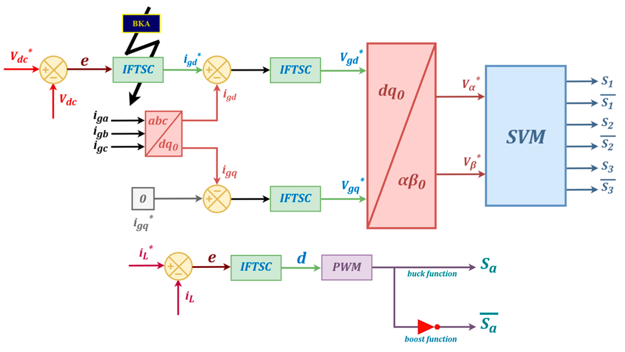
In G2V mode, the three-phase AC-DC converter operates as a boost rectifier and acts as an inverter in V2G mode. In G2V operation, the battery charging process follows and realizes a two-stage constant current-constant voltage (CC-CV) strategy, whereas, in V2G mode, a single constant current discharging process is implemented with negative current reference. The bidirectional DC-DC converter is responsible for executing the CC-CV charging/discharging profile. To ensure high-performance control, a robust nonlinear control strategy is developed as presented in Figure 3 with the following objectives:
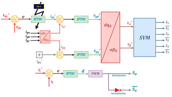
Figure 3.
Overall control scheme.
- Maintaining the unity power factor by keeping the three-phase grid currents and voltages sinusoidal in phase.
- Regulating the DC-link voltage accurately to its predefined reference value.
- Providing a safe and reliable process for charging and discharging the battery in both G2V and V2G modes.
3.1. Integral Synergetic Controller
Integral synergetic control (ISC) theory is a nonlinear state-space-based control methodology initially introduced in [45], primarily for specific applications such as DC-DC converters [46,47]. Recently, the authors in [48,49] have employed ISC theory in microgrid applications. ISC theory presents similarities with sliding mode control (SMC), notably in terms of system order reduction and the natural decoupling of system state variables. However, ISC provides several advantages over SMC, including fewer tuning parameters, mitigation of chattering effects, and complete controllability of the reaching phase. The core goal of ISC is to drive the system states into a predefined manifold known as the sliding manifold. This is achieved through the formulation of a macro-variable, which is a mathematical expression constructed based on system modeling and control objectives. This macro-variable typically combines system states or state errors. The system’s dynamic behavior is then governed by the prescribed evolution of this macro-variable toward the desired manifold. The general form of this evolution is defined as
The macro-variable function is expressed by
where is a positive definite variable gain that defines the convergence speed of the macro-variables towards the intersection of manifolds. is the error between the state variables compared with their reference values. And are real constant numbers.
The main goal of the ISC scheme is to regulate the DC-link voltage , the grid current , and the battery current following their respective reference values. More details are presented in the following subsection.
3.1.1. DC-Bus Voltage Control Design
In this section, the ISC strategy is applied to regulate the DC-bus voltage to its reference value and generate the grid current reference.
The error of the state variables in this case is chosen as follows:
The macro-variable is written as
Applying Equation (9), we get
By solving Equation (13), the control law Can be found as follows:
Figure 4 shows the block diagram of ISC for DC-bus voltage control.

Figure 4.
Block diagram of ISC for DC-bus voltage control.
3.1.2. Grid-Connected Control Design
The ISC technique is used to control the grid currents by defining the voltage reference values, which are used as inputs in the SVM to generate the control pulses of the three-phase AC/DC converter. In addition, these voltage reference values are calculated based on the grid current mathematical model presented in Equation (3).
In this case, the error of the state variables can be expressed as follows:
The macro-variable is defined as
where and , the diagonal matrices with positive values, are defined as
and
Also, we take
Equation (18) is obtained by substituting Equation (16) in Equation (9),
By solving Equation (18), the control law and can be found as follows:
where
Figure 5 shows the block diagram of ISC for grid current control.

Figure 5.
Block diagram of ISC for grid current control.
3.1.3. Bidirectional Buck-Boost Control Design
To control the battery current in both modes, the ISC strategy is applied to track and force the output current into its reference value. Therefore, we take the battery current as a state variable that should be controlled and the duty cycle as the control action.
We choose the error of the state variables as follows:
The expression of a macro-variable can be written as
The duty cycle can be found by solving Equation (22), as follows:
The block diagram of ISC for bidirectional Buck-Boost control is presented in Figure 6.

Figure 6.
Block diagram of ISC for bidirectional Buck-Boost control.
3.2. Integral Fast Terminal Synergetic Controller
The Integral Fast Terminal Synergetic Control (IFTSC) is an advanced strategy that forces the system states to reach zero within a finite time [50,51] by reducing the reaching phase duration. This approach was enhanced in [52] through the development of a fast terminal SC by introducing an additional error term to the manifold function to guarantee the convergence to a desired manifold, as shown in [52,53]. In this work, the macro-variable used for the integral fast terminal SC is defined as follows:
where
It is a definite constant matrix and the parameters and are odd numbers satisfying such that this addition of the nonlinear term improves the transient performance of the reaching mode and robustness.
By taking the same procedure as ISC, the control system is decomposed into independent control loops as follows.
3.2.1. DC-Bus Voltage Control Design
The IFTSC strategy is designed to regulate the DC-bus voltage , and provides the grid current .
The selected state variable error that represents the objective of this controller is expressed as follows:
The macro-variable defined by IFTSC theory is written as
By applying Equation (9), Equation (27) can be represented as
The grid current can be found by solving Equation (28), as follows:
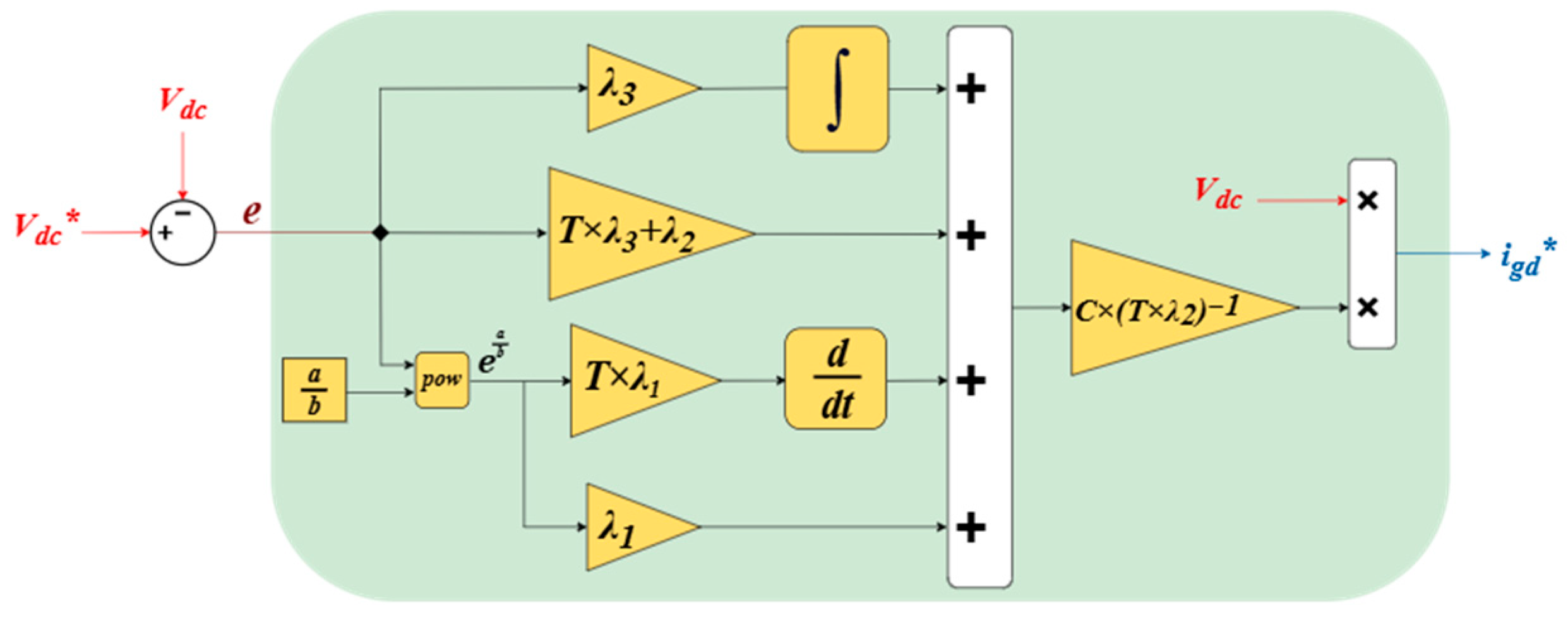
The block diagram of IFTSC for DC-bus voltage control is illustrated in Figure 7.
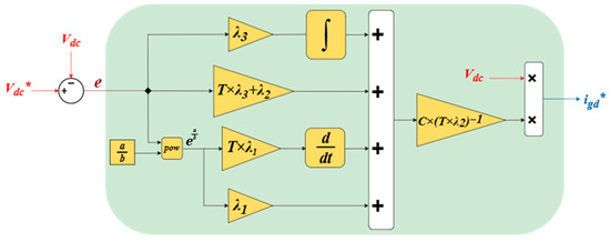
Figure 7.
Block diagram of IFTSC for DC-bus voltage control.
3.2.2. Grid-Connected Control Design
The IFTSC approach regulates the grid currents by establishing voltage reference values that serve as inputs for the SVM, which generate control pulses for the three-phase AC/DC converter. Furthermore, these voltage reference values are generated from the grid current controller.
We choose the error of the state variables as follows:
According to IFTSC theory, the macro-variable is defined as follows:
Applying the function of state variables, we get the following:
The control low , can be described by solving Equation (31), as
where
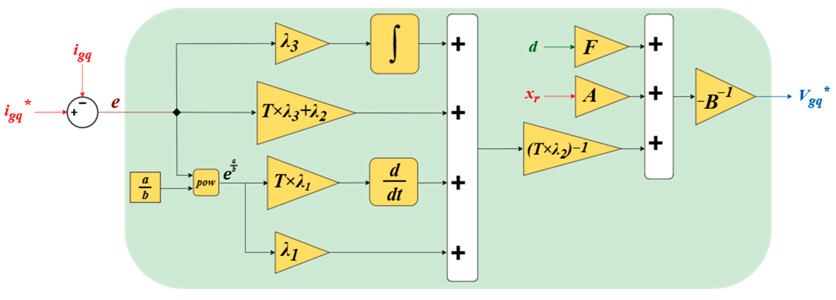
Figure 8 displays the block diagram of IFTSC for grid current control.
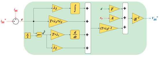
Figure 8.
Block diagram of IFTSC for grid current control.
3.2.3. Bidirectional Buck-Boost Control Design
In this section, the IFTSC strategy is applied to control the battery current in both modes to a reference value. For this reason, the battery current is considered as a state variable and the duty cycle as a control action.
The error of the state variable is defined as follows:
The macro-variable can be described by Equation (35)
By substituting Equation (35) in Equation (9), Equation (9) can be rewritten as follows:
Equation (36) is solved to obtain the control low as
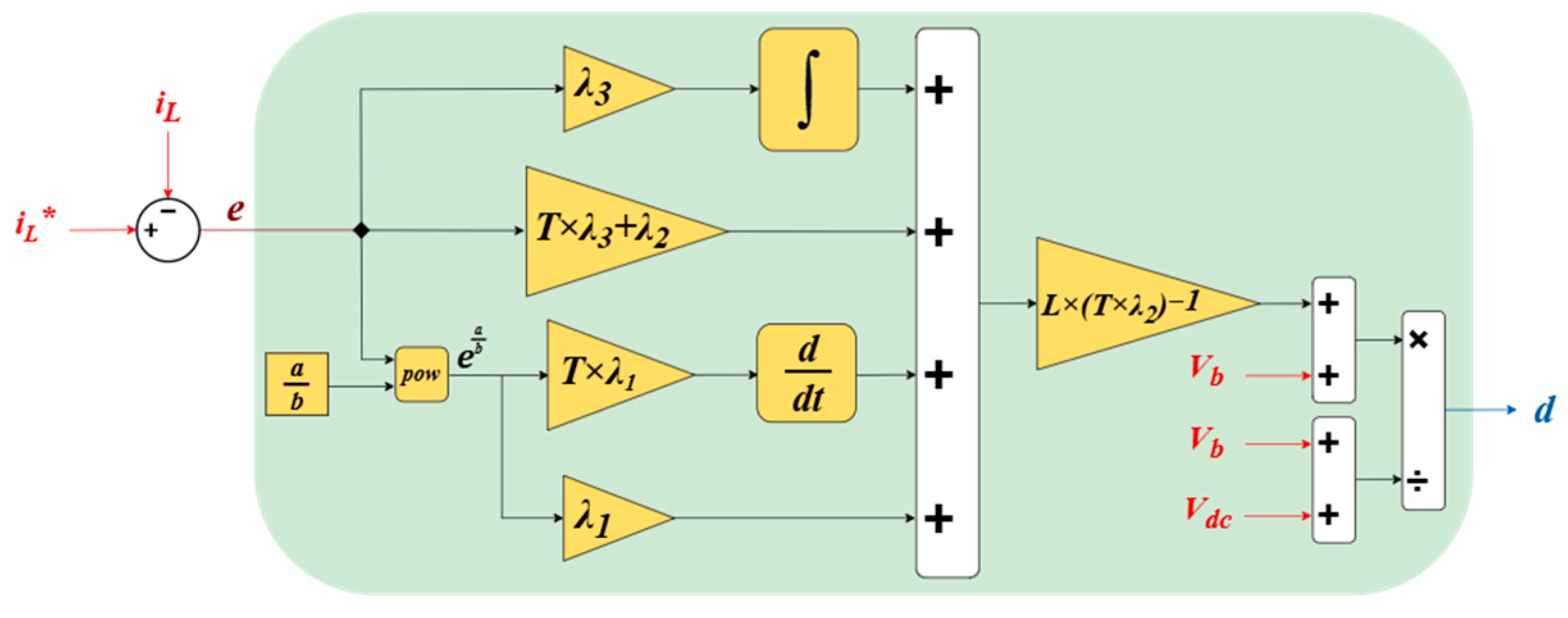
The block diagram of IFTSC for bidirectional Buck-Boost control is exhibited in Figure 9.
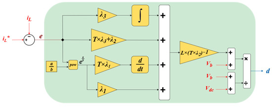
Figure 9.
Block diagram of IFTSC for bidirectional Buck-Boost control.
4. Stability Proof of the Proposed Control Scheme
As a first step, we define the Lyapunov equation as the Euclidean norm of the macro-variable function, which is given as [54,55]
where
Considering the macro-variable function defined in the previous sections. The derivative of the Lyapunov equation is written as
Therefore, SC technique stability is guaranteed due to the negative derivative of the Lyapunov function.
4.1. Integral Synergetic Control Stability Proof
For the ISC control, we will prove the system stability for each independent control loop.
4.1.1. Stability Analysis of Grid-Connected Control Scheme Based on ISC
To prove the system when ISC for the grid current controller is applied, Equation (37) is derived in the time dimension, which yields
By substituting from its definition in Equation (19), Equation (41) leads to
Replacing the low control of Equation (20) and simplifying the resultant equations gives
After mathematical simplification, Equation (43) is written as
It can be seen that the value of the time derivative in Equation (44) is negative all the time. Therefore, the suggested system with the ISC scheme is stable for any suggested values of .
4.1.2. Stability Analysis of DC-Bus Controller Based on ISC
The system stability in the case of ISC for the DC-bus voltage controller is analyzed by the derivative of the Lyapunov equation as
From Equations (13) and (45), Equation (46) can be expressed as
To simplify Equation (46), the control low is replaced by its equation as follows:
Equation (47) is simplified as follows:
It can be observed that the value of the time derivative in Equation (48) is negative all the time. Consequently, the studied system with the ISC DC-bus voltage controller is stable for any suggested values of .
4.1.3. Lyapunov-Based Stability Investigation for Bidirectional Buck-Boost with ISC
The derivative of the Lyapunov equation in the case of bidirectional Buck-Boost with the ISC controller is described as
By replacing by its equation, Equation (49) can be expressed as
Then, Equation (50) can be rewritten by substituting the control low by its equation as
Equation (51) can be simplified as follows:
From Equation (52), the derivative is always negative. Then, the bidirectional Buck-Boost system with ISC scheme is stable for any suggested values of .
4.2. Integral Fast Terminal Synergetic Control Stability Proof
To simplify the stability proof, we take each independent control loop separately, where the macro-variable for this section is always given as
4.2.1. Stability Analysis of Grid-Connected Control Scheme Based on IFTSC
The suggested system with grid-connected IFTSC stability is checked by the derivative of the Lyapunov equation as
The is replaced by its expression presented in Equation (32), which leads to
With substitution of the control law in Equation (33), the Lyapunov function derivation can be expressed as follows:
After a few algebraic steps, Equation (56) is rewritten as
According to Equation (57), the proposed IFTSC meets the Lyapunov stability criteria. , which ensures the system stability for any suggested values of .
4.2.2. Stability Analysis of DC-Bus Controller Based on IFTSC
To check the stability of the studied system with a DC-bus controller based on IFTSC, the derivatives of the Lyapunov equation yield
By using Equation (27), Equation (58) is simplified as follows:
The grid current is replaced by its expression in Equation (28) as
The Equation (60) is simplified after a few algebraic steps as
Equation (61) proves that is negative all the time. Then, the system with its suggested control scheme is stable for any suggested values of .
4.2.3. Lyapunov-Based Stability Investigation for Bidirectional Buck-Boost with IFTSC
In this case, the derivative of the Lyapunov equation yields
By substituting the expression of , Equation (63) can be written as
The duty cycle expression is replaced in Equation (63) as
Equation (64) is simplified after some algebraic steps as
is always negative according to Equation (65). Then, the system with its IFTSC control scheme is stable for any suggested values of .
5. Black-Winged Kite Algorithm (BKA)
5.1. Mathematical Model of BKA
This section presents the mathematical formulation of the BKA algorithm as a straightforward and efficient meta-heuristic optimization technique, which is categorized into two fundamental features: attacking and migration behaviors [33].
5.1.1. Initialization Step
The initial phase of populating the BKA involves generating a set of random solutions. The position of each black-winged kite (BK) can be shown using the following matrix:
where pop and dim denote the quantity of possible solutions and the size of the problem’s dimension, respectively. Each position of BKA is represented as follows:
In the initialization process, we choose the individual with the highest fitness value as the leader in the original population. The mathematical representation is as follows:
5.1.2. Attacking Behavior
This behavior encompasses many offensive tactics for exploration and search.
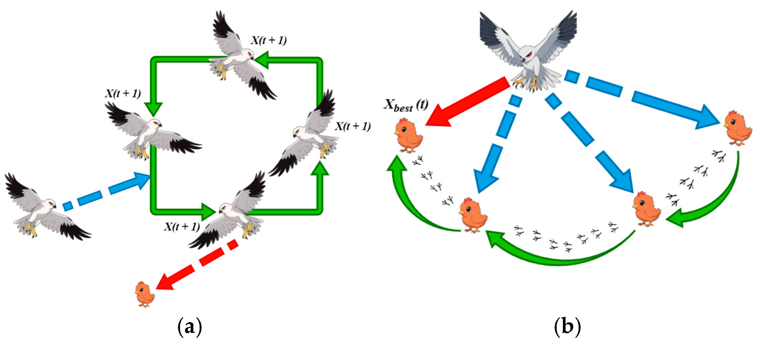
Figure 10a depicts a black-winged kite suspended in the air, with its wings extended and equilibrium preserved. Figure 10a depicts the black-winged kite swiftly approaching the target. Furthermore, Figure 10a illustrates the attack posture of the black-winged kite during its aerial hover, whereas Figure 10b depicts the black-winged kite in a similar hovering state. A mathematical model representing this behavior is expressed in the following equation:
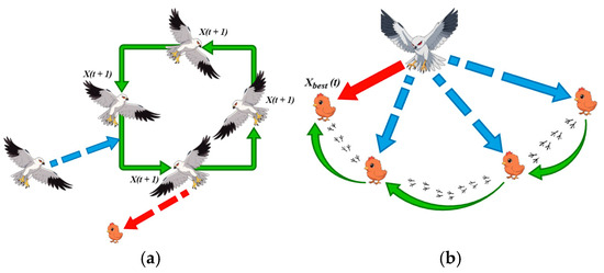
Figure 10.
Two attack strategies of black-winged kites are (a) hovering in the air, waiting for an attack, and (b) hovering in the air, searching for prey.
Figure 10a depicts the attack state of the black-winged kite as it hovers in the air, while Figure 10b shows the condition of the black-winged kite as it hovers in the air.
and denote the location of the black-winged kites in the dimension. is a random number . , represent the total number of iterations and the number of iterations that have been completed so far, respectively.
5.1.3. Migration Behavior
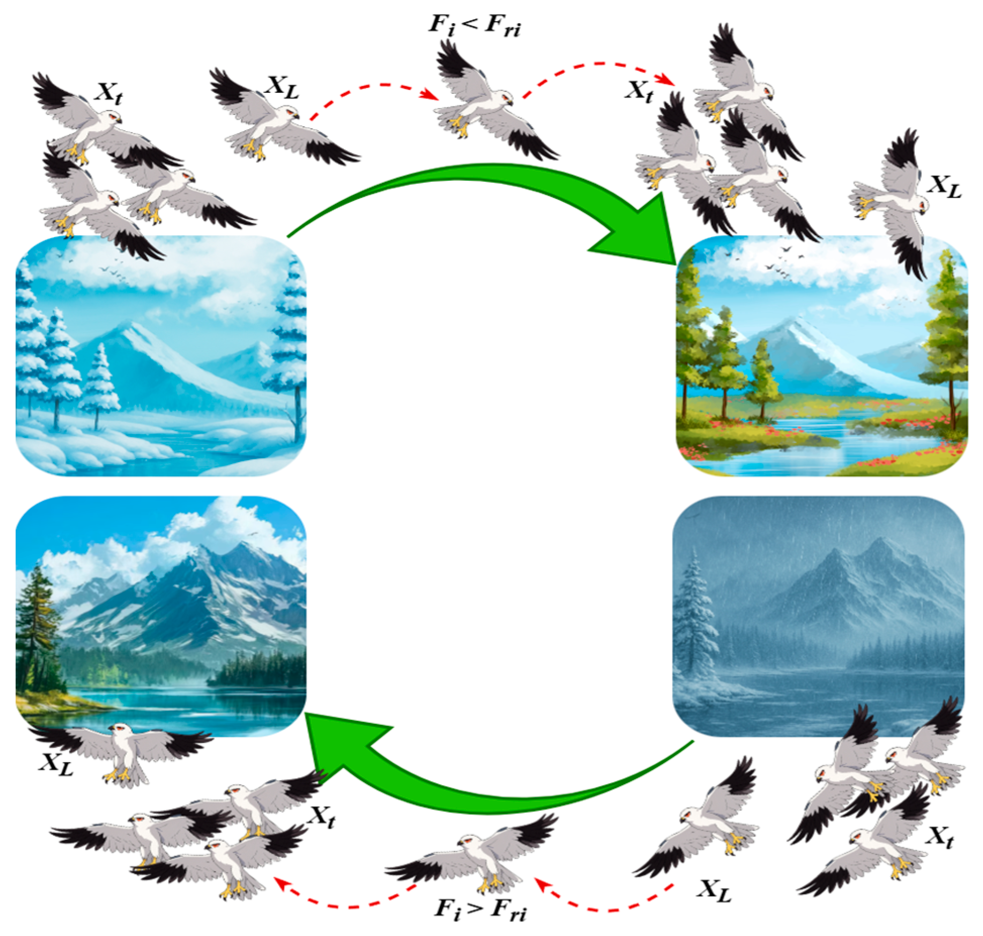
We present a theory about avian migration: if the fitness value of the current population is inferior to that of a random population, the leader will relinquish leadership and integrate into the migrating population, signifying an inadequacy in leading the population.
If the fitness value of the present population exceeds that of the random population, it will direct the population towards its objective. This strategy is presented in Figure 11. This technique may dynamically identify exceptional leaders to guarantee a successful migration, as seen in the following equation.
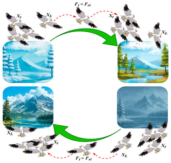
Figure 11.
The strategic changes of black-winged kites during migration pseudo-code of BKA.
represents the leading scorer in the dimension of the iteration so far. and represent, respectively, the current and random positions obtained.
5.2. BKA in DC-Bus Optimized Design
To improve the control performance of the IFTSC for a G2V and V2G battery electric vehicle charger, the selection of optimal gains of the suggested control is considered in this section. The BKA algorithm is employed with IFTSC to regulate the output voltage to its reference value with high-performance control. The position variable is chosen as follows:
To minimize
where k1 and k2 are the weighting factors. They are chosen by trial and error to provide a good trade-off between minimizing the errors and ensuring that the control signal is not too big. Nevertheless, the challenge of optimally adjusting the controller coefficients may be described as a standard restricted optimization problem with five coefficients (). The minimization of f(X) is subject to
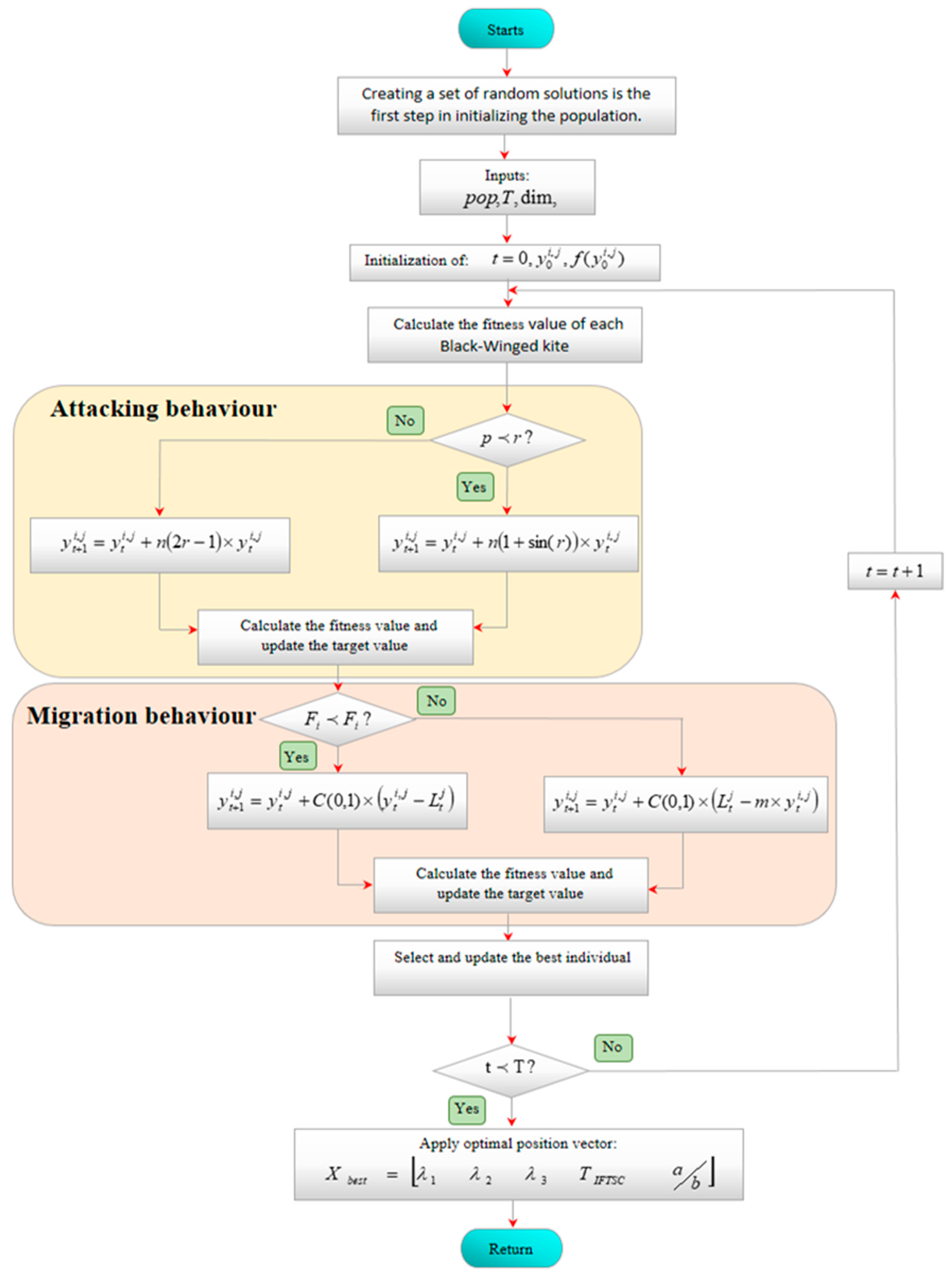
The functionality of the BK algorithm is summarized in Figure 12. The BKA uses parameter p to regulate various attack behaviors and improve the balance among these concerns. At the same time, variable n will decrease nonlinearly as the number of iterations increases, facilitating a transition in the approach from a global search to a local search, thus expediting the identification of the optimal solution and reducing the risk of converging on local optima, ultimately enhancing the resolution of practical issues.
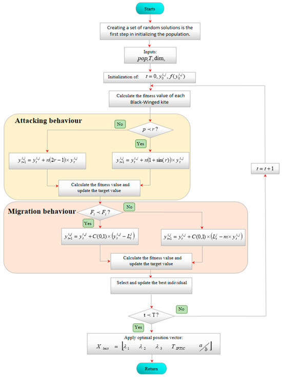
Figure 12.
Flowchart of the proposed BKA.
Diversity is crucial in intelligent optimization algorithms, since it prevents the population from converging on local optima and facilitates a broader search space, hence enhancing the possibility of identifying global optima. Similarly to many advanced optimization approaches, the individuals in the initial population of this article are chosen at random within a specified range, leading to variations in their positions and eigenvalues, thereby imparting a degree of diversity to the population and enhancing the exploration of the solution space. During the algorithm’s iterative phase, the implementation of the Cauchy strategy, which is represented by C(0, 1), and the judicious configuration of parameters enhance the algorithm’s variety, augment its global search capability, and prevent convergence to local optima.
6. Test Types and Simulation Results
In this section, simulation results are presented and discussed for the proposed optimal IFTSC and other control strategies. These simulations are conducted for the G2V/V2G system using MATLAB/Simulink and SimPower System packages (R2016b, MathWorks, Natick, MA, USA). The overall system parameters are detailed in Table 1. The optimal parameters of the proposed controller are listed in Table 2. The studied system was tested under a series of step changes in the battery current reference at t = 0.3s, t = 0.6, and t = 0.9, in order to evaluate the dynamic response and robustness of the proposed control strategies.

Table 1.
Overall system parameters.

Table 2.
Optimal IFTSC parameters.
6.1. Initial G2V Operation
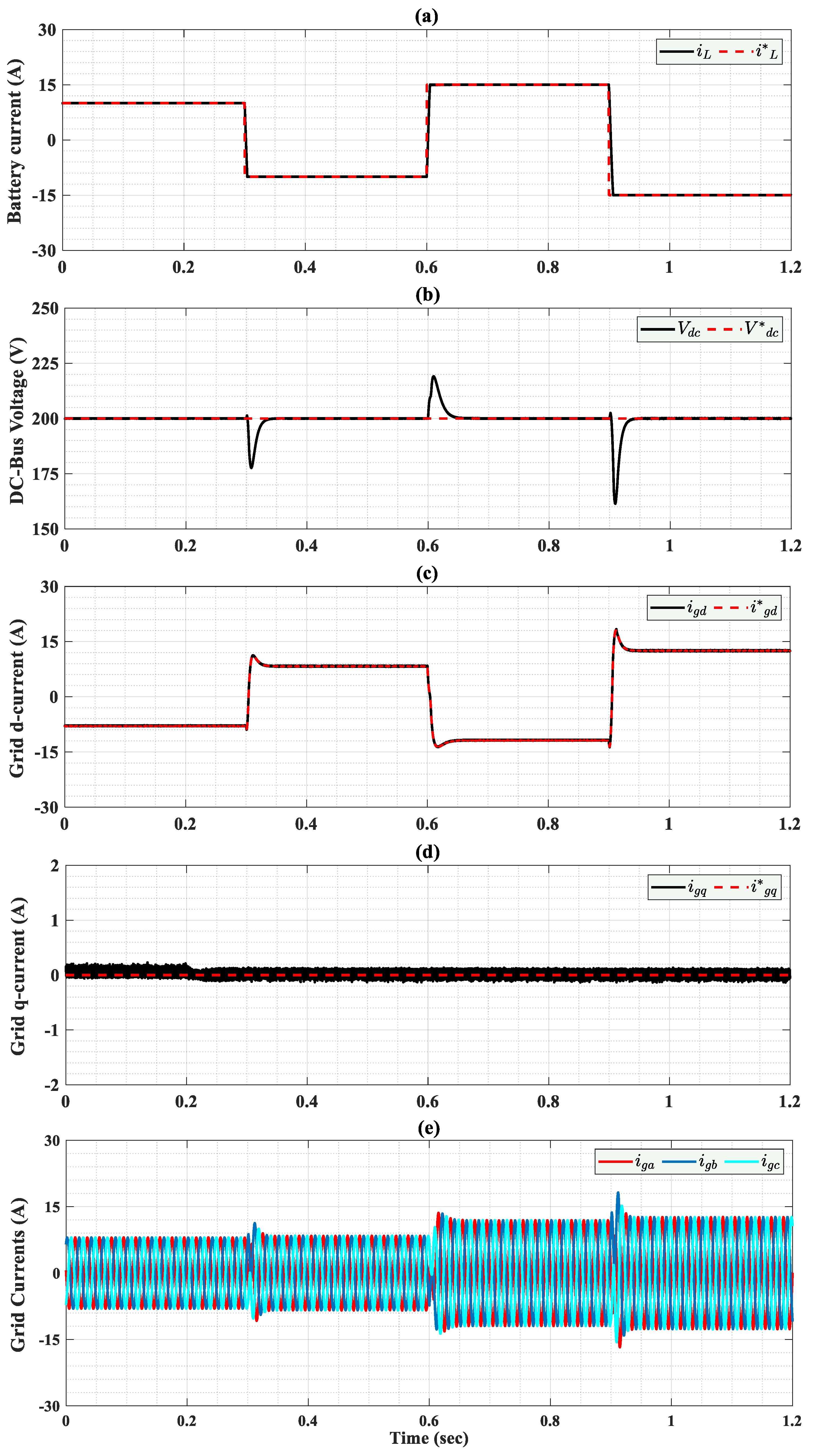
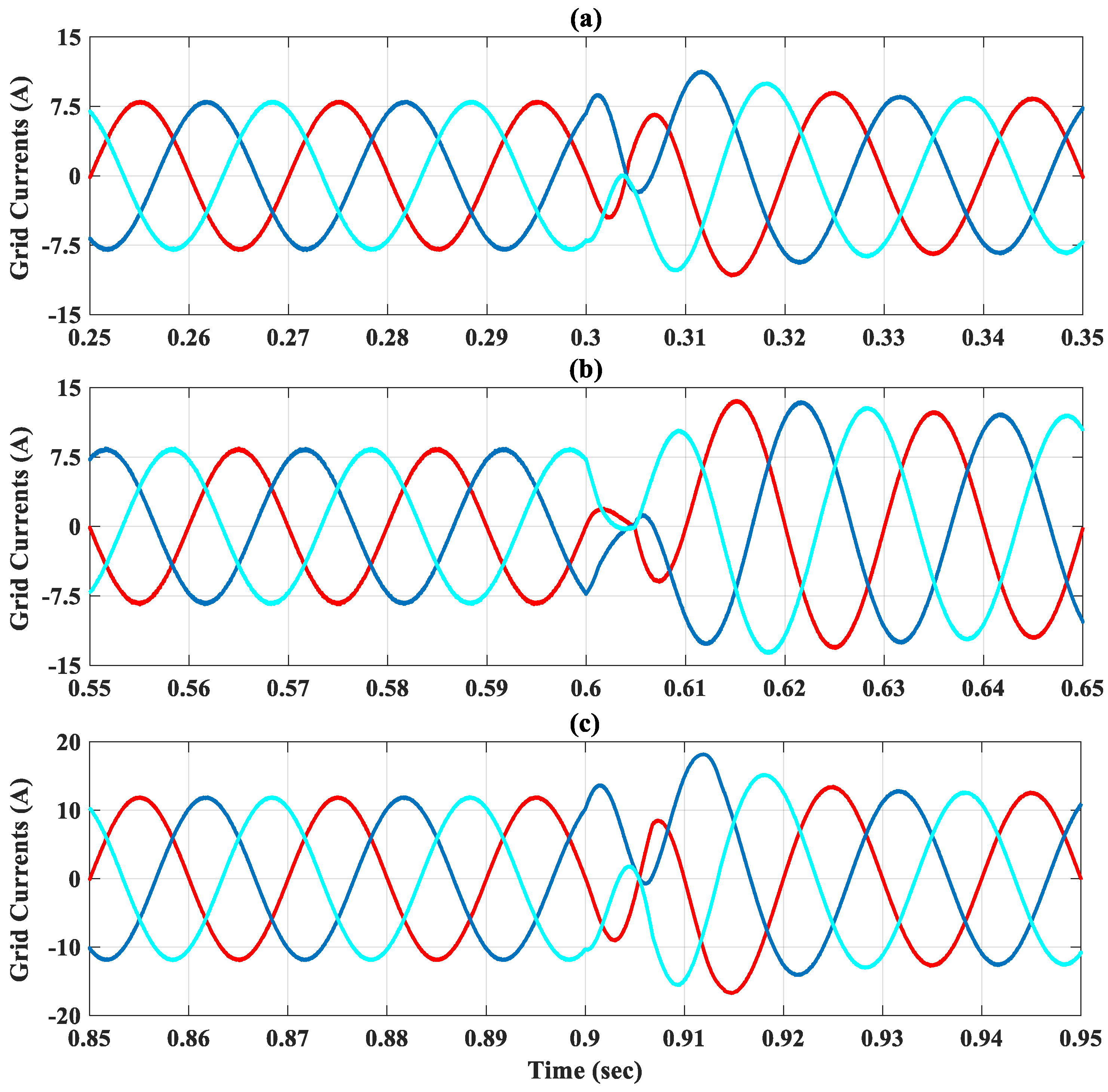
At t = 0 s, the charging process begins with a battery current reference of 10 A. The OIFTSC controller ensures that the battery current tracks its reference accurately with rapid convergence. Simultaneously, the DC-bus voltage is regulated to its reference value of 200 volts, exhibiting fast transient response with minimal steady-state error, as shown in Figure 13a. Furthermore, the dq grid currents follow their references precisely as illustrated in Figure 13c,d. The measured grid currents are balanced with a sinusoidal form as presented in Figure 13e and Figure 14.
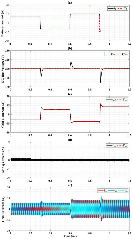
Figure 13.
Simulated different responses with OIFTS controllers during variation in reference battery current; (a) The battery current during G2V/V2G modes; (b) The DC-bus voltage during G2V/V2G modes; (c) The grid d-current during G2V/V2G modes; (d) The grid q-current during G2V/V2G modes; (e) The grid’s current during G2V/V2G modes.
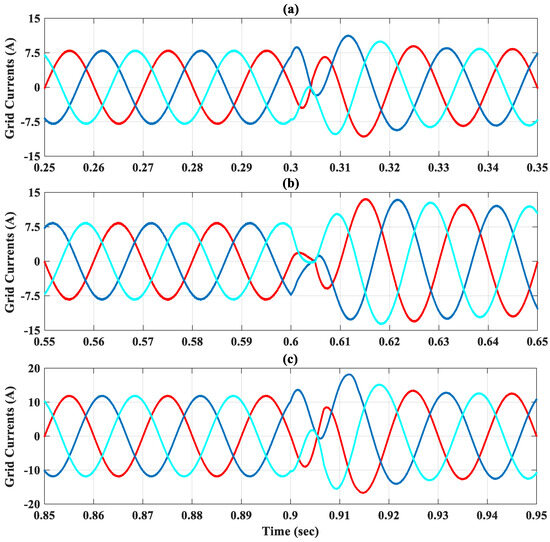
Figure 14.
Zoom out on grid current during three transitions; (a) First transition; (b) Second transition; (c) Third transition.
6.2. Transition to V2G
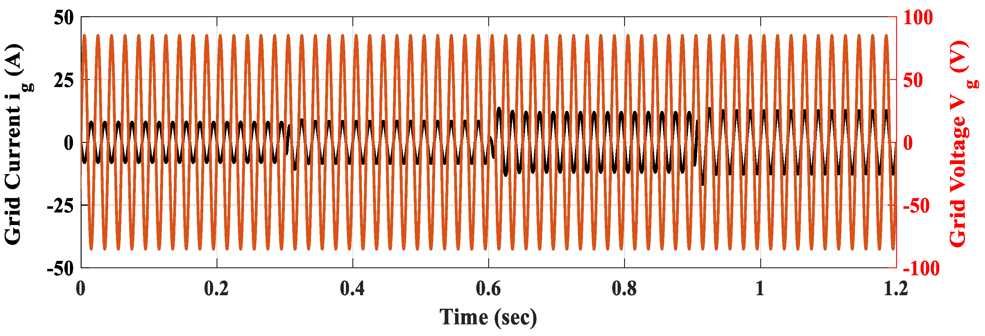
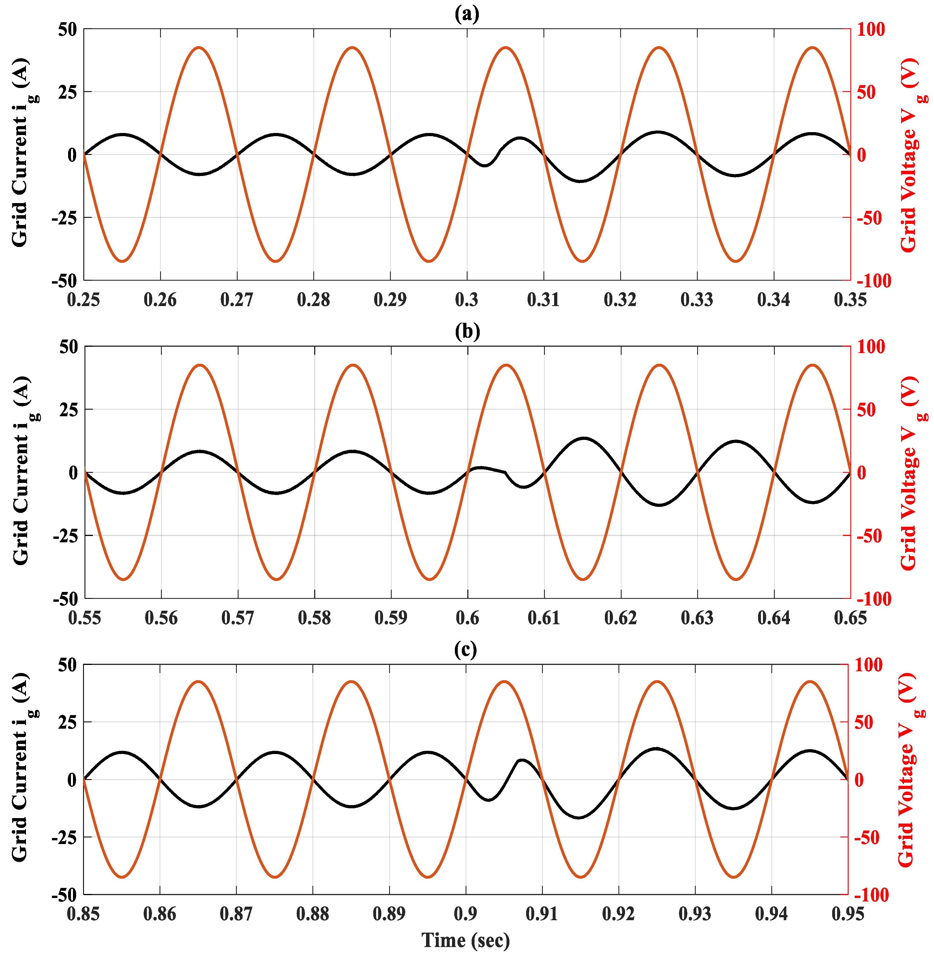
At t = 0.3 s, the battery current reference is abruptly changed from 10 A to −10 A, stimulating a transition to the discharging V2G mode. The proposed OIFTS controller reacts promptly with the battery current and converges smoothly to the set point as seen in Figure 13a. The DC-bus voltage remains closely regulated around its nominal value after a small undershoot. Figure 13c,d show that the dq grid currents track their references perfectly. The grid currents effectively change the angle as shown in Figure 15 and Figure 16a, and remain in the sinusoidal form presented in Figure 13e and Figure 14.
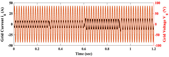
Figure 15.
Grid current and voltage during G2V/V2G switching modes.
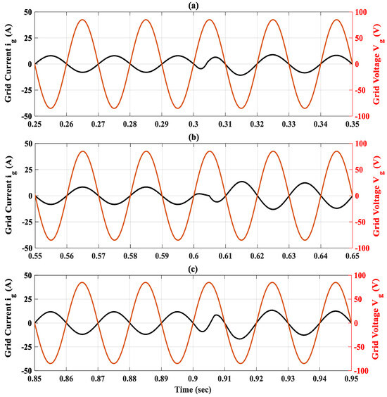
Figure 16.
Zoom out on grid current and voltage under three transitions; (a) First transition; (b) Second transition; (c) Third transition.
At t = 0.6 s, the battery current reference is increased from −10 A to 15 A. Despite the aggressive step change, the OIFTS controller maintains robust performance: the battery current quickly settles to its new reference, as shown in Figure 13a. The DC-bus voltage continues to follow the 200 volts reference accurately after an overshoot. The dq grid currents are well regulated to their references as depicted in Figure 13c,d. The grid current’s amplitude is increased due to the increase in the amplitude of the battery current reference. Moreover, Figure 13e and Figure 14 show that the grid angle is changed, while preserving sinusoidal waveforms, and remains in phase with the grid voltage as presented in Figure 15 and Figure 16b.
At t = 0.9 s, the battery current reference is suddenly switched from 15 A to −15 A, introducing a high-magnitude undershoot disturbance. As shown in Figure 13a, the measured battery current rapidly converges with negligible steady-state error. This significant change in the battery current reference leads to an undershoot in the DC-bus voltage, , as shown in Figure 13b. The dq-grid currents once again change polarity and track their references with high fidelity, as presented in Figure 13c,d, confirming the bidirectional operating capability of the studied system using the OIFTSC. Figure 15 and Figure 16c demonstrate that the grid currents change their angle and remain in sinusoidal form.
Table 3 demonstrates the total harmonic distortion (THD%) across all steady states of the source current with five different control strategies. The proposed optimal IFTSC reduces the THDi% of the grid current more than the other control schemes. This provides strong evidence of the effectiveness of the proposed control technique and enhances the grid current quality.

Table 3.
Performances comparison in terms of THD%.
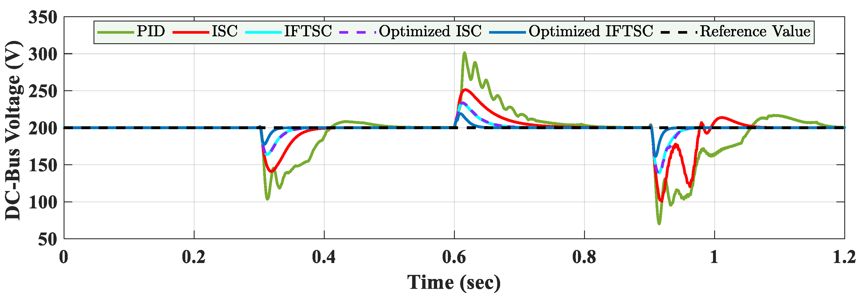
To validate the superiority of the proposed control scheme, a comparative analysis is conducted among five controllers: classical PID, Integral Synergetic Control (ISC), Integral Fast Terminal Synergetic Control (IFTS), Optimized ISC, and the proposed Optimized IFTSC. The DC-bus voltage response under three consecutive step variations in the battery current reference at t = 0.3 s, t = 0.6 s, and t = 0.9 s is illustrated in Figure 17.
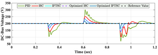
Figure 17.
Simulated DC-bus voltage responses with different controllers during variation in reference battery current.
The PID controller demonstrates inadequate voltage regulation with substantial undershoot, overshoot, and prolonged oscillations following each disturbance. ISC enhances the transient performance but still suffers from slow convergence and moderate deviations. IFTSC further enhances the response, reducing voltage overshoots and obtaining faster settling. Upon performing parameter adjustment, the performance of ISC is greatly improved, resulting in superior stability and disturbance rejection. However, the Optimized IFTSC demonstrates the best dynamic performance among all controllers, holding the DC-bus voltage within a narrow deviation range and promptly converging to the reference value after each transient event.
These results verify that the integration of fast terminal synergetic control with optimal tuning leads to higher voltage regulation and improved overall performance. This supports the efficiency of the proposed Optimized IFTSC for bidirectional charger applications.
For more details, the key figures obtained for the different controllers are presented in Table 4. It shows the high performance of our proposed control strategy under disturbances compared to other methods, which confirms the robustness of the proposed controller.

Table 4.
Quantitative performance analysis of the different controllers in terms of settling time, overshoot/undershoot, and RMSE.
Despite the presence of parameter changes (80%Lg, 80%Cv, 80%Lh) and grid voltage harmonic disturbances, the proposed control strategy demonstrates strong robustness. As shown in Figure 18, the DC-link voltage remains well regulated, with only minor transient deviations, indicating effective disturbance rejection and voltage stabilization. In Figure 19, the grid voltage and current remain sinusoidal and in-phase, confirming that the controller maintains a unitary power factor, even under grid voltage harmonic perturbations. These results validate the controller’s performance in realistic grid scenarios and its capacity to operate reliably in complex environments.

Figure 18.
DC-link waveform under parameter disturbance.

Figure 19.
Grid current and voltage waveforms under grid voltage harmonic disturbance.
The proposed OIFTSC controller demonstrates strong harmonic suppression capabilities, maintaining THD well under all tested conditions, as presented in Table 5. This confirms its robustness and effectiveness in both ideal and disturbed operating scenarios.

Table 5.
Total harmonic distortion (THD%) of the proposed control strategy under several conditions.
7. Co-Simulation Results
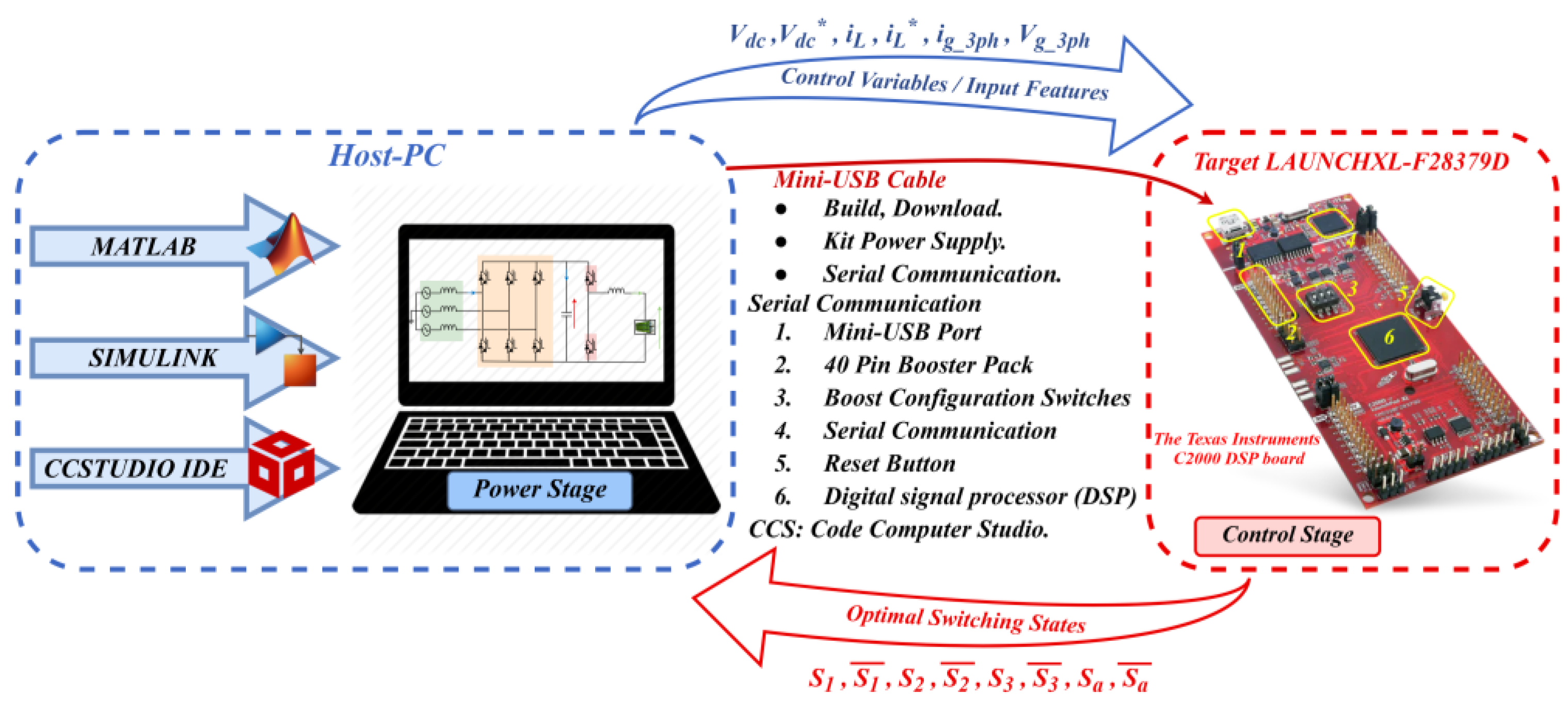
In this section, an efficient prototyping technique was implemented to execute the proposed control strategy that was previously mentioned in Section 3. More specifically, a processor-in-the-loop (PIL) installation was used to evaluate and validate experimentally our proposed control strategy for regulating a grid-to-vehicle and vehicle-to-grid battery electric vehicle charger. Figure 20 describes the main components and input/output signal flows in PIL co-simulation for the proposed control scheme, which is implemented using a DSP card C2000-microcontroller-LuncherPad F28379D that contains a 32-bit microcontroller with 1 Mbyte flash memory, a clock frequency of 168 MHz, a floating-point unit, DSP instructions, and 192 Kbytes SRAM. In this configuration, the control algorithm is executed in real-time on the C2000 microcontroller, while the converters, sources, and different loads of the proposed power scheme are simulated and designed in the host computer as an electric circuit in MATLAB/Simulink. The PIL simulation necessitates interaction between the host PC and the Target LAUNCHXL-F28379D, which is executed by applying a virtual serial COM port [56]. Therefore, the host PC emits the measured signals to the LAUNCHXL F28379D kit. Then, the suggested control approach determines the optimum switching state that will be implemented in the next sampling instant. Finally, the host PC receives the control signals, . This procedure is repeated each sampling time.
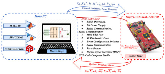
Figure 20.
Schematic diagram of the PIL co-simulation for the proposed system, with the main components and signal flow [57].
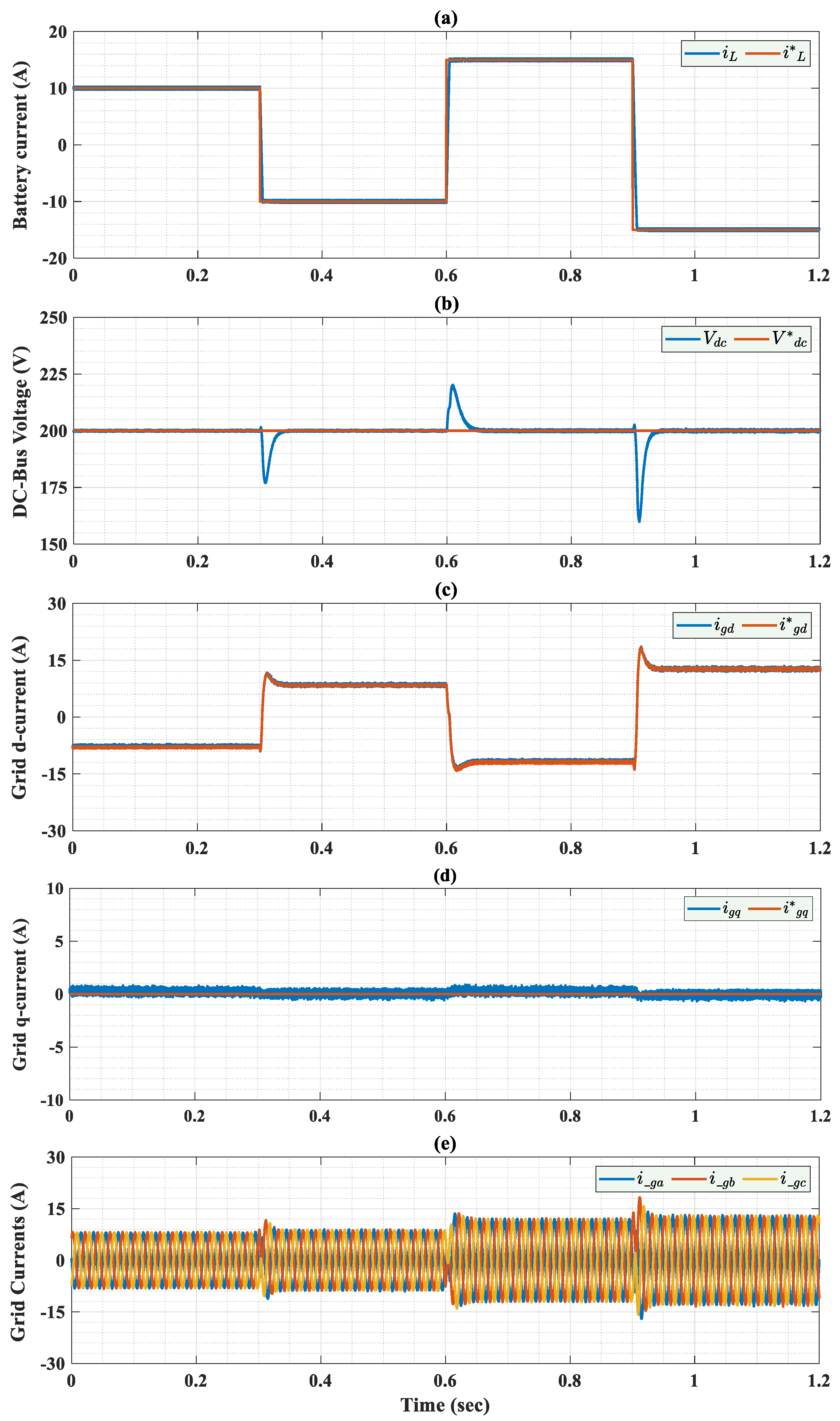
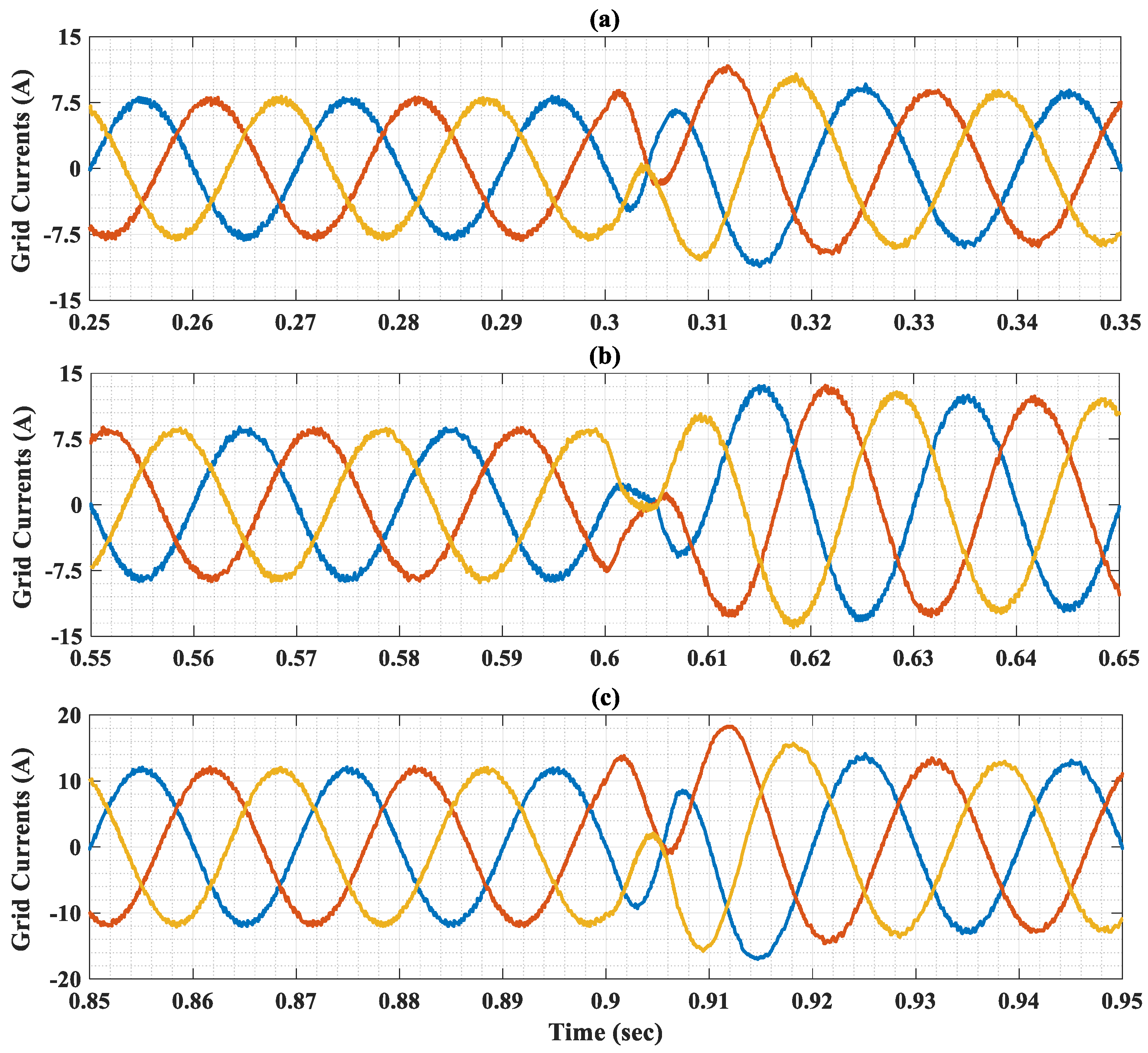
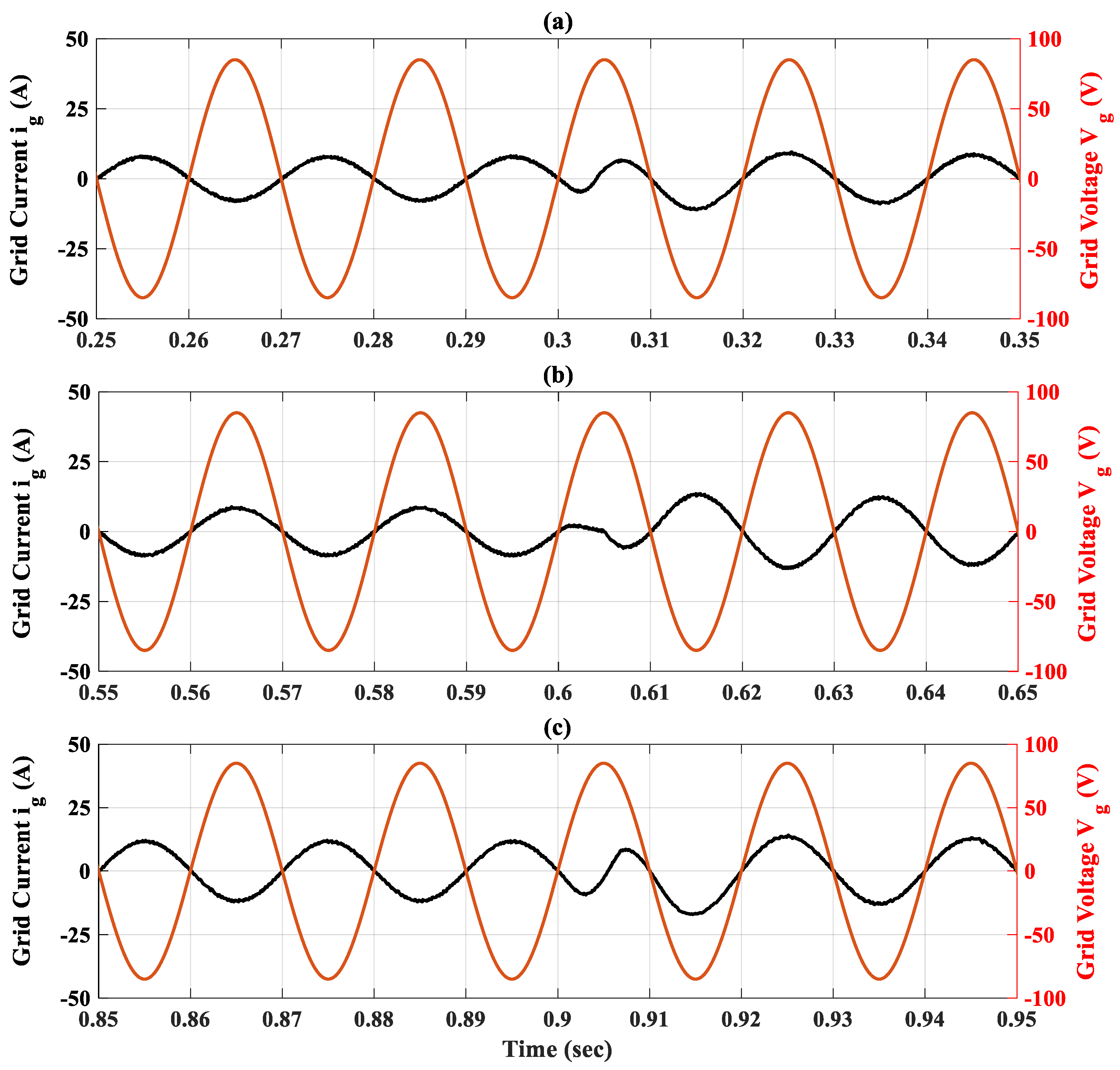
Figure 21, Figure 22, Figure 23 and Figure 24 show the PIL experimental results of the proposed OIFTSC. Initially, the battery current is accurately tracking the reference value under the same profile perturbations that have been used in the simulation section, with a small response time. The DC-bus voltage is highly regulated to its reference with good accuracy and stability during the load changes with a drop voltage lower than 30 V in both G2V–V2G transitions. Furthermore, Figure 21c,d illustrate a rapid convergence of igd at the set point changes, while igq remains almost zero at steady state to ensure a unit power factor. Finally, the grid current exhibits perfectly sinusoidal waveforms synchronized with the grid voltage, as shown in Figure 21e, validating the robustness of the proposed control strategy.
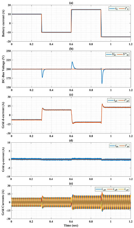
Figure 21.
Experimental responses of BEV charger system controlled by the OIFTS controller. (a) Battery current; (b) DC-bus voltage; (c)
and its reference; (d) and its reference ; (e) Three-phase grid currents under variable input current reference.
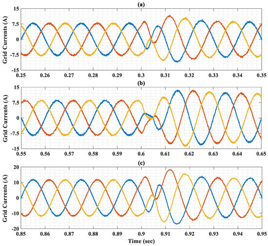
Figure 22.
Zoom out on the grid current during the three transitions: (a) First transition; (b) Second transition; (c) Third transition.

Figure 23.
Experimental results of grid current , grid voltage under variable input current reference.
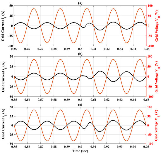
Figure 24.
Zoom out on grid current and voltage under three transitions; (a) First transition; (b) Second transition; (c) Third transition.
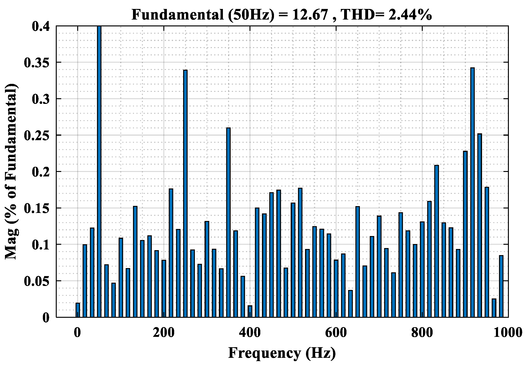
Finally, Table 6 and Figure 25 show the effectiveness of the proposed control meeting IEEE standards 519-1992 for all operating modes, with a THD varying between 3.9% and 2.4%.

Table 6.
Analysis of grid current THD%.
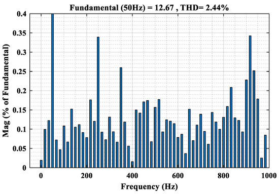
Figure 25.
Harmonic spectrum of the grid current results at t = 1.6 s.
8. Conclusions
The control of power flow in both directions of grid-connected electric vehicle charging stations is studied in this paper. A robust control scheme based on an Integral Fast Terminal Synergetic (IFTS) control theory is proposed to control the BEV charger system by precisely tracking the required current and voltage in both G2V and V2G system modes. The optimal gains of the proposed IFTS control scheme are estimated using the Black-Winged Kite Algorithm. The Lyapunov stability method is used to check the system’s stability. The optimal IFTS control scheme demonstrated its performance by extensive simulations using MATLAB/Simulink and processor-in-the-loop (PIL) co-simulation using the C2000 launchxl-f28379d digital signal processing (DSP) board under diverse operation scenarios and compared to IFTS, optimal integral synergetic, integral synergetic, and conventional PID controllers. The simulation outcomes show that the optimal IFTS control scheme guarantees high dynamic performance with accurate reference tracking under a step change in the battery current reference. Furthermore, the proposed control scheme ensures a unitary power factor of the AC grid, as well as providing high grid current quality compared to other control schemes.
Author Contributions
Conceptualization, I.A. and A.L.; methodology, I.A., Y.S., and A.L.; software, validation, I.A. and Y.S.; formal analysis, I.A. and A.L.; investigation, A.L. and I.A.; resources, A.L. and Y.S.; data curation, I.A., Y.S., and A.L.; writing—original draft preparation, I.A. and Y.S.; writing—review and editing, A.L.; visualization, A.L. All authors have read and agreed to the published version of the manuscript.
Funding
This research received no external funding.
Data Availability Statement
The original contributions presented in this study are included in the article. Further inquiries can be directed to the corresponding author.
Conflicts of Interest
The authors declare no conflict of interest.
References
- El Fadil, H.; Belhaj, F.Z.; Rachid, A.; Giri, F.; Ahmed-Ali, T. Nonlinear modeling and observer for supercapacitors in electric vehicle applications. IFAC-PapersOnLine 2017, 50, 1898–1903. [Google Scholar] [CrossRef]
- Jia, C.; Liu, W.; He, H.; Chau, K.T. Superior energy management for fuel cell vehicles guided by improved DDPG algorithm: Integrating driving intention speed prediction and health-aware control. Appl. Energy 2025, 394, 126195. [Google Scholar] [CrossRef]
- Dubey, A.; Santoso, S. Electric vehicle charging on residential distribution systems: Impacts and mitigations. IEEE Access 2015, 3, 1871–1893. [Google Scholar] [CrossRef]
- Shi, L.; Lv, T.; Wang, Y. Vehicle-to-grid service development logic and management formulation. J. Mod. Power Syst. Clean Energy 2019, 7, 935–947. [Google Scholar] [CrossRef]
- Oad, A.; Ahmad, H.G.; Talpur, M.S.H.; Zhao, C.; Pervez, A. Green smart grid predictive analysis to integrate sustainable energy of emerging V2G in smart city technologies. Optik 2023, 272, 170146. [Google Scholar] [CrossRef]
- Allehyani, A.; Ajabnoor, A.; Alharbi, M. Chapter 14- demand response scheme for electric vehicles charging in smart power systems with 100% of renewable energy. In Power Systems Operation with 100% Renewable Energy Sources; Chenniappan, S., Padmanaban, S., Palanisamy, S., Eds.; Elsevier: Amsterdam, The Netherlands, 2024; pp. 247–268. [Google Scholar]
- Ding, B.; Li, Z.; Li, Z.; Xue, Y.; Chang, X.; Su, J.; Sun, H. Cooperative Operation for Multiagent Energy Systems Integrated with Wind, Hydrogen, and Buildings: An Asymmetric Nash Bargaining Approach. IEEE Trans. Ind. Inform. 2025, 2025, 1–12. [Google Scholar] [CrossRef]
- Zhai, X.; Li, Z.; Li, Z.; Xue, Y.; Chang, X.; Su, J.; Jin, X.; Wang, P.; Sun, H. Risk-averse energy management for integrated electricity and heat systems considering building heating vertical imbalance: An asynchronous decentralized approach. Appl. Energy 2025, 383, 125271. [Google Scholar] [CrossRef]
- Ahmed, I.; Adil, H.M.M.; Ahmed, S.; Ahmed, I.; Rehman, Z. Robust nonlinear control of battery electric vehicle charger in grid to vehicle and vehicle to grid applications. J. Energy Storage 2022, 52, 104813. [Google Scholar] [CrossRef]
- Kumar, P.; Channi, H.K.; Kumar, R.; Rajiv, A.; Kumari, B.; Singh, G.; Dyab, I.F.; Lozanović, J. A comprehensive review of vehicle-to-grid integration in electric vehicles: Powering the Future. Energy Convers. Manag. X 2024, 25, 100864. [Google Scholar] [CrossRef]
- Sultan, V.; Aryal, A.; Chang, H.; Kral, J. Integration of EVs into the smart grid: A systematic literature review. Energy Inform. 2022, 5, 65. [Google Scholar] [CrossRef]
- Mojumder, M.R.H.; Antara, F.A.; Hasanuzzaman, M.; Alamri, B.; Alsharef, M. Electric Vehicle-to-Grid (V2G) Technologies: Impact on the Power Grid and Battery. Sustainability 2022, 14, 13856. [Google Scholar] [CrossRef]
- Zabihi, A.; Parhamfar, M. Decentralized energy solutions: The impact of smart grid-enabled EV charging stations. Heliyon 2025, 19, e41815. [Google Scholar] [CrossRef]
- Vishnu, G.; Kaliyaperumal, D.; Jayaprakash, R.; Karthick, A.; Chinnaiyan, V.K.; Ghosh, A. Review of Challenges and Opportunities in the Integration of Electric Vehicles to the Grid. World Electr. Veh. J. 2023, 14, 259. [Google Scholar] [CrossRef]
- Maheriya, A.; Raval, A.S.; Panchal, S.; Borisagar, K. Empowering the Future of Smart Grids: Unveiling the Role of Electric Vehicles in V2G Integration for Sustainable Infrastructure. In E-Mobility in Electrical Energy Systems for Sustainability; Chamkha, A.J., Saidur, R., Mohammed, M.A., Eds.; IGI Global: Hershey, PA, USA, 2023; pp. 227–256. [Google Scholar] [CrossRef]
- Seth, A.K.; Singh, M. Plant Integrated Proportional Integrating Based Control Design for electric vehicle charger. Comput. Electr. Eng. 2023, 105, 108522. [Google Scholar] [CrossRef]
- Premchand, M.; Gudey, S.K. Analysis of PI, PR and SMC Controllers for Bidirectional Converter Used in Electric Vehicle. In Advances in Automation, Signal Processing, Instrumentation, and Control; Komanapalli, V.L.N., Sivakumaran, N., Hampannavar, S., Eds.; Lecture Notes in Electrical Engineering; Springer: Singapore, 2021; Volume 700, pp. 449–466. [Google Scholar] [CrossRef]
- Singirikonda, S.; Obulesu, Y.P.; Kannan, R.; Reddy, K.J.; Kumar, G.K.; Alhakami, W.; Baz, A.; Alhakami, H. Adaptive control-based Isolated bi-directional converter for G2V& V2G charging with integration of the renewable energy source. Energy Rep. 2022, 8, 11416–11428. [Google Scholar] [CrossRef]
- Goto, T.; Kodaira, D. Optimal Control of Battery System by Reinforcement Learning Considering Profitability. In Proceedings of the International Conference on Power and Renewable Energy Engineering (PREE), Tokyo, Japan, 20–22 October 2023; pp. 12–16. [Google Scholar] [CrossRef]
- Jia, C.; Liu, W.; He, H.; Chau, K.T. Deep reinforcement learning-based energy management strategy for fuel cell buses integrating future road information and cabin comfort control. Energy Convers. Manag. 2024, 321, 119032. [Google Scholar] [CrossRef]
- He, T.; Zhu, J.; Lu, D.D.C.; Zheng, L. Modified Model Predictive Control for Bidirectional Four-Quadrant EV Chargers with Extended Set of Voltage Vectors. IEEE J. Emerg. Sel. Top. Power Electron. 2019, 7, 274–281. [Google Scholar] [CrossRef]
- He, T.; Wu, M.; Lu, D.D.C.; Aguilera, R.P.; Zhang, J.; Zhu, J. Designed Dynamic Reference with Model Predictive Control for Bidirectional EV Chargers. IEEE Access 2019, 7, 129362–129375. [Google Scholar] [CrossRef]
- Mohammed, A.M.; Alalwan, S.N.H.; Taşcıkaraoğlu, A.; Catalão, J.P.S. Sliding Mode-Based Control of an Electric Vehicle Fast Charging Station in a DC Microgrid. Sustain. Energy Grid Netw. 2022, 32, 100820. [Google Scholar] [CrossRef]
- Cheddadi, Y.; El Idrissi, Z.; Errahimi, F.; Es-sbai, N. Robust Integral Sliding Mode Controller Design of a Bidirectional DC Charger in PV-EV Charging Station. Int. J. Digit. Signals Smart Syst. 2021, 5, 137–151. [Google Scholar] [CrossRef]
- Mishra, D.; Singh, B.; Panigrahi, B.K. Adaptive Current Control for a Bidirectional Interleaved EV Charger with Disturbance Rejection. IEEE Trans. Ind. Appl. 2021, 57, 4080–4090. [Google Scholar] [CrossRef]
- Saadaoui, A.; Ouassaid, M. Super-twisting sliding mode control approach for battery electric vehicles ultra-fast charger based on Vienna rectifier and three-phase interleaved DC/DC buck converter. J. Energy Storage 2024, 84 Pt B, 110854. [Google Scholar] [CrossRef]
- Ahmed, I.; Adnan, M.; Ali, M.; Kaddoum, G. Supertwisting sliding mode controller for grid-to-vehicle and vehicle-to-grid battery electric vehicle charger. J. Energy Storage 2023, 70, 107914. [Google Scholar] [CrossRef]
- Rajendran, S.; Jena, D.; Diaz, M.; Rodríguez, J. Terminal Integral Synergetic Control for Wind Turbine at Region II Using a Two-Mass Model. Processes 2023, 11, 616. [Google Scholar] [CrossRef]
- Li, Y.; Shi, B.; Qiao, W.; Du, Z. A black-winged kite optimization algorithm enhanced by osprey optimization and vertical and horizontal crossover improvement. Sci. Rep. 2025, 15, 6737. [Google Scholar] [CrossRef]
- Laib, A.; Talbi, B.; Krama, A.; Gharib, M. Hybrid interval type-2 fuzzy PID+ I controller for a multi-DOF oilwell drill-string system. IEEE Access 2022, 10, 67262–67275. [Google Scholar] [CrossRef]
- Jain, D.; Bhaskar, M.K.; Parihar, M. Optimization of Controller Parameters for Load Frequency Control Problem of Two-Area Deregulated Power System Using Soft Computing Techniques. In Proceedings of Congress on Control, Robotics, and Mechatronics; Jha, P.K., Tripathi, B., Natarajan, E., Sharma, H., Eds.; Springer Nature: Singapore, 2024; pp. 385–401. [Google Scholar] [CrossRef]
- Gul, B.T.; Ahmad, I.; Rehman, H.; Hasan, A. Optimized ANFIS-Based Robust Nonlinear Control of a Solar Off-Grid Charging Station for Electric Vehicles. IEEE Access 2025, 13, 20361–20373. [Google Scholar] [CrossRef]
- Abdel-Basset, M.; Mohamed, R.; Hezam, I.M.; Sallam, K.M.; Hameed, I.A. Parameters identification of photovoltaic models using Lambert W-function and Newton-Raphson method collaborated with AI-based optimization techniques: A comparative study. Expert Syst. Appl. 2024, 255 Pt D, 124777. [Google Scholar] [CrossRef]
- Mahmud, K.; Town, G.E.; Morsalin, S.; Hossain, M.J. Integration of electric vehicles and management in the internet of energy. Renew. Sustain. Energy Rev. 2018, 82 Pt 3, 4179–4203. [Google Scholar] [CrossRef]
- Rubino, L.; Capasso, C.; Veneri, O. Review on plug-in electric vehicle charging architectures integrated with distributed energy sources for sustainable mobility. Appl. Energy 2017, 207, 438–464. [Google Scholar] [CrossRef]
- Yahya, A.; El Fadil, H.; Oulcaid, M.; Ammeh, L.; Giri, F.; Guerrero, J.M. Control of grid connected photovoltaic systems with microinverters: New Theoretical Design and Numerical Evaluation. Asian J. Control. 2018, 20, 906–918. [Google Scholar] [CrossRef]
- Tahri, A.; El Fadil, H.; Belhaj, F.Z.; Gaouzi, K.; Rachida, A.; Giri, F.; Chaoui, F.Z. Management of fuel cell power and supercapacitor state-of-charge for electric vehicles. Electr. Power Syst. Res. 2018, 160, 89–98. [Google Scholar] [CrossRef]
- Rachid, A.; El Fadil, H.; Gaouzi, K.; Rachid, K.; Lassioui, A.; El Idrissi, Z.; Koundi, M. Electric vehicle charging systems: Comprehensive review. Energies 2022, 16, 255. [Google Scholar] [CrossRef]
- Cui, X.; Avestruz, A.T. Fast-response variable frequency DC-DC converters using switching cycle event-driven digital control. IEEE Trans. Power Electron. 2023, 38, 8190–8207. [Google Scholar] [CrossRef]
- Elnady, A.; Noureldin, A.; Adam, A.A. Improved Synergetic Current Control for Grid-connected Microgrids and Distributed Generation Systems. J. Mod. Power Syst. Clean Energy 2022, 10, 1302–1313. [Google Scholar] [CrossRef]
- Deffaf, B.; Farid, H.; Benbouhenni, H.; Medjmadj, S.; Debdouche, N. Synergetic control for three-level voltage source inverter-based shunt active power filter to improve power quality. Energy Rep. 2023, 10, 1013–1027. [Google Scholar] [CrossRef]
- Wang, K.; Liu, D.; Wang, L. The Implementation of Synergetic Control for a DC-DC Buck-Boost Converter. Procedia Comput. Sci. 2022, 199, 900–907. [Google Scholar] [CrossRef]
- Badoud, A.E.; Merahi, F.; Ould Bouamama, B.; Mekhilef, S. Bond Graph Modeling, Design and Experimental Validation of a Photovoltaic/Fuel Cell/ Electrolyzer/Battery Hybrid Power System. Int. J. Hydrog. Energy 2021, 46, 24011–24027. [Google Scholar] [CrossRef]
- Kanouni, B.; Badoud, A.E.; Mekhilef, S.; Bajaj, M.; Zaitsev, I. Advanced Efficient Energy Management Strategy Based on State Machine Control for Multi-Sources PV-PEMFC-Batteries System. Sci. Rep. 2024, 14, 7996. [Google Scholar] [CrossRef]
- Kolesnikov, A.; Veselov, G. Modern Applied Control Theory: Synergetic Approach. In Control Theory; TRTU: Taganrog, Russia, 2000; pp. 4477–4479. [Google Scholar]
- Kolesnikov, A.; Veselov, G.; Kolesnikov, A.; Monti, A.; Ponci, F.; Santi, E.; Dougal, R. Synergetic synthesis of DC-DC boost converter controllers: Theory and experimental analysis. In Proceedings of the APEC Seventeenth Annual IEEE Applied Power Electronics Conference and Exposition, Dallas, TX, USA, 10–14 March 2002; Volume 1, pp. 409–415. [Google Scholar] [CrossRef]
- Li, D.; Proddutur, K.; Santi, E.; Monti, A. Synergetic Control of a boost converter: Theory and experimental verification. In Proceedings of the IEEE Southeast Conference, Columbia, SC, USA, 5–7 April 2002; pp. 197–200. [Google Scholar] [CrossRef]
- Qian, J.; Li, K.; Wu, H.; Yang, J.; Li, X. Synergetic control of grid-connected photovoltaic systems. Int. J. Photoenergy 2017, 2017, 5051489. [Google Scholar] [CrossRef]
- Yu, Z.; Ai, Q.; Gong, J.; Piao, L. A novel secondary control for microgrid based on Synergetic Control of multi-agent system. Energies 2016, 9, 243. [Google Scholar] [CrossRef]
- Komurcugil, H. Adaptive terminal sliding-mode control strategy for DC-DC converters. ISA Trans. 2012, 51, 673–681. [Google Scholar] [CrossRef] [PubMed]
- Abderrezek, H.; Harmas, M.N. Particle swarm optimization of a terminal synergetic controllers for a DC-DC converter. Int. J. Electr. Comput. Electron. Commun. Eng. 2014, 8, 8. [Google Scholar]
- Zerroug, N.; Harmas, M.N.; Benaggoune, S.; Bouchama, Z.; Zehar, K. DSP-based implementation of fast-terminal synergetic control for a DC-DC Buck converter. J. Frankl. Inst. 2018, 355, 2329–2343. [Google Scholar] [CrossRef]
- Elnady, A.; Noureldin, A.; Adam, A.A. Integral terminal synergetic based direct power control for distributed generation systems. IEEE Trans. Smart Grids 2022, 13, 1287–1297. [Google Scholar] [CrossRef]
- Boudouani, S.; Yahdou, A.; Benbouhenni, H.; Boudjema, Z.; Almalki, M.M.; Alghamdi, T.A. Enhanced speed sensorless control of IPMSM using integral synergetic observer. Meas. Control. 2025, 58, 1–10. [Google Scholar] [CrossRef]
- Niu, H.; Lan, Q.; Liu, Y.; Xu, H. A continuous integral terminal sliding mode control approach for a class of uncertain nonlinear systems. Meas. Control. 2019, 52, 720–728. [Google Scholar] [CrossRef]
- Ebrahim, M.A.; Aziz, B.A.; Nashed, M.N.; Osman, F.A. Op timal design of proportional-resonant controller and its harmonic compensators for grid-integrated renewable energy sources based three-phase voltage source inverters. IET Gener. Transm. Distrib. 2021, 15, 1371–1386. [Google Scholar] [CrossRef]
- Zaid, S.A.; Mohamed, I.S.; Bakeer, A.; Liu, L.; Albalawi, H.; Tawfiq, M.E.; Kassem, A.M. From MPC-based to end to-end (E2E) learning-based control policy for grid-tied 3L-NPC transformerless inverter. IEEE Access 2022, 10, 57309–57326. [Google Scholar] [CrossRef]
Disclaimer/Publisher’s Note: The statements, opinions and data contained in all publications are solely those of the individual author(s) and contributor(s) and not of MDPI and/or the editor(s). MDPI and/or the editor(s) disclaim responsibility for any injury to people or property resulting from any ideas, methods, instructions or products referred to in the content. |
© 2025 by the authors. Licensee MDPI, Basel, Switzerland. This article is an open access article distributed under the terms and conditions of the Creative Commons Attribution (CC BY) license (https://creativecommons.org/licenses/by/4.0/).


