Article

Thermo-Hydrodynamic Features of Grooved Heat Sink with Droplet-Shaped Fins Based on Taguchi Optimization and Field Synergy Analysis

1
Tianjin Lantian Solar Technology Co., Ltd., Tianjin 300392, China
2
School of Energy and Safety Engineering, Tianjin Chengjian University, Tianjin 300384, China
*
Author to whom correspondence should be addressed.
Energies 2025, 18(13), 3396; https://doi.org/10.3390/en18133396
Submission received: 8 June 2025 / Revised: 23 June 2025 / Accepted: 25 June 2025 / Published: 27 June 2025

Abstract

In recent years, the number of transistors on electronic chips has surpassed Moore’s law, resulting in overheating and energy consumption problems in data centers (DCs). Chip-level microchannel cooling is expected to address these challenges. Grooved heat sinks with droplet-shaped fins were introduced to modify the overall capability of the cooling system. The degree of impact of the distribution of grooves and fins was analyzed and optimized using the Taguchi method. Moreover, the coupling effect of flow and temperature fields was explained using the field synergy theory. The key findings are as follows: for thermal resistance, pump power, and overall efficiency, the influence degree is the number of combined units > number of fins in each unit > distribution of the combined units. The optimal configuration of 21 combined units arranged from dense to sparse with one fin in each unit achieves 14.05% lower thermal resistance and 8.5% higher overall efficiency than the initial heat sink. The optimal configuration of five combined units arranged from sparse to dense with one fin in each unit reduces the power energy consumption by 27.61%. After optimization, the synergy angle between the velocity vector and temperature gradient is reduced by 4.29% compared to the smooth heat sink. The coupling effect between flow and heat transport is strengthened. The optimized configuration can better balance heat dissipation and energy consumption, improve the comprehensive capability of cooling system, provide a feasible solution to solve the problems of local overheating and high energy consumption in DCs.

1. Introduction

The continuous growth of the computing power of data centers (DCs) causes a substantial increase in the transient heat generation of electronic chips and excessive energy consumption by cooling systems, and the space for heat dissipation is very limited. The overtemperature will reduce the data processing speed of core components and even cause equipment failures. This threatens the safe operation of the electronic chip in DCs seriously [1]. Chip-level microchannel liquid cooling has the characteristics of efficient heat transport, accurate temperature control, and easy integration. It is considered an effective means of removing ultra-high heat fluxes (107 W/m2) in limited cooling areas [2,3].
The disturbance structures in microchannel heat sinks (MCHSs) usually induce periodic variations in flow and temperature fields, which promotes the interruption of flow and thermal boundary layers, chaotic convection, and fluid mixing. The configuration and distribution of micro structures directly affect thermal and hydraulic characteristics [4,5,6]. Modifying the sidewall configuration with grooves, ribs, or porous media can effectively improve the heat dissipation efficiency. Fathi et al. [7] proposed a semi-porous-fin MCHS to enhance the thermal conductivity of the whole-porous-fin MCHS. Thermal resistance was reduced by 11.12% compared to the solid-fin counterparts at the optimal porous height ratio. Cui et al. [8] introduced a hybrid heat sink consisting of micro-jet impingement and microchannels with ribbed walls. The temperature homogeneity was significantly improved by the enhanced fluid disturbance. An artificial neural network (ANN) was employed to obtain the optimal parameter. Chen et al. [9] discussed the thermo-hydraulic features of manifold MCHSs with various ribs and compared them with those of a smooth configuration. The cooling efficiency of the novel MCHS was improved at the cost of a pressure drop penalty, with the elliptical ribs exhibiting the best thermal enhancement efficiency.
The combination of the pin-fin assembly and other micro-structures can induce vortexes in different dimensions, leading to enhanced heat transport and fluid mixing. Bhandari et al. [10] discussed the impact of stepped fin on the thermo-hydraulic performance of a micro heat sink. The fins with different heights were more conducive to heat transport compared to those of equal height, owing to enhanced mixing caused by out-of-plane fluid motion. Wang et al. [11] designed a MCHS with water droplet-shaped cavities and fins, and the layout and column size of the fins were discussed. Gradually increasing the diameter of fins along the flow direction could effectively improve temperature uniformity. Liu et al. [12] compared the thermo-hydraulic features of a manifold MCHS with open configuration and a manifold micro pin-fin heat sink with open configuration. They found that the open configuration induced low-speed vortexes and increased temperature inhomogeneity. The manifold MCHSs without open configuration presented superior cooling efficiency. Sahel et al. [13] conducted a numerical investigation on the combination configurations of the splitters, transversal fins and pin fins with holes. They argued that the innovative design enhanced the heat transport while reducing the dimension and mass of the heat sink. Xue et al. [14] designed a micro-jet heat sink with pin fins. The jet nozzle holes and pin fins with variable density could eliminate a local hotspot with a heat flux of 700 w/cm2.
Optimizing the flow path can alleviate the temperature rise of the working medium, improve temperature uniformity in the heat sink, and reduce flow resistance [15,16]. Ma et al. [17] examined the thermo-hydraulic features in a sinusoidal MCHS. They found that the period of the sinusoidal structure had an obvious impact on the temperature distribution, thermal resistance, and pump power. The configuration with a decreasing period along the flow direction reduced thermal resistance with a small increase in pump power. Wang et al. [18] put forward a multi-layered microchannel cold plate for CPU-package cooling. The various distributions of inlet/outlet and channel layer numbers were discussed. A modified stepped microchannel with indium as thermal interface material obtained the best overall capability. Song et al. [19] introduced a novel heat exchanger with an alveolar lattice metastructure, which exhibited a superior heat transport rate because of the increased contact area, the tortuous primary flow and various vortex pairs.
However, complex structures often increase the pressure drop, resulting in increased energy consumption and packaging difficulties, which poses challenges for the application of microchannel liquid cooling. Therefore, it is very important to clarify the influence mechanism of different configurations on thermal and hydrodynamic characteristics and find out the effective method to enhance heat dissipation within an acceptable pump power range. The field synergy theory brought forward by Guo et al. [20] was adopted to estimate heat transport from the inherent relation of velocity and temperature fields by some investigators. A good coupling between the velocity vector and temperature gradient is the fundamental mechanism underlying thermal transport improvement [21,22]. In addition, it is necessary to conduct multi-objective optimization for high cooling efficiency, low energy consumption, and good temperature equalization. The quantitative analysis of parameter sensitivity is crucial for finding out the key factors affecting flow and heat transfer, which pave the way for balancing the heat removal and power energy consumption of the cooling system. Some researchers used the Taguchi method to analyze the importance of the geometric parameters of heat sinks and obtained the optimal configurations [23,24]. Shi et al. [25] suggested that the staggered fins with varying height and density could enhance the cooling efficiency and temperature control capability. The relative importance of fin geometric factors was determined by the Taguchi method. Tang et al. [26] employed field synergy angle and multi-objective optimization to elucidate the coupling mechanism of flow and temperature fields and to improve the overall performance of MCHSs with ribs.
The streamlined configuration of the droplet-shaped fin can enhance flow disturbance, albeit with an acceptable pressure drop. He et al. [27] carried out a numerical simulation on the electrothermal coupling behaviors of TSV in the deformation configurations of droplet-shaped fins. The layout and parameters of the fin and TSV played a key role in the electrothermal coupling effect. Jia et al. [28] embedded droplet-shaped fins in microchannels and examined the influence of fin distribution on thermo-hydraulic characteristics. The uniform arrangement showed better overall performance. In our previous work, the microchannel with triangular grooves and droplet-shaped fins acquired superior overall performance because of the intensified heat transport, with a slightly increased pressure drop [29]. However, the layout of combined structures has not been studied thoroughly, despite its direct impact on multi-physics fields and thermo-hydrodynamic features. Layout optimization is an effective approach to modify overall performance. In addition, the synergy analysis for the flow and temperature fields can further clarify the physical mechanism of heat transport enhancement of this kind of configuration, guiding the optimal design of MCHSs.
To this end, the Taguchi method was applied to elucidate the importance of the number and layout of grooves and fins. The contribution ratios of different cases to thermal resistance, pump power, and the figure of merit (FOM) were summarized. The cooling capacity, thermo-hydraulic characteristics, and comprehensive performance of the optimal configurations were clarified. Moreover, the coupling effect of the heat transport and fluid dynamics in the optimal layouts was explored using the field synergy theory. The physical mechanism of the layout of grooves and fins on heat transport improvement was elucidated.

2. Model and Numerical Solution

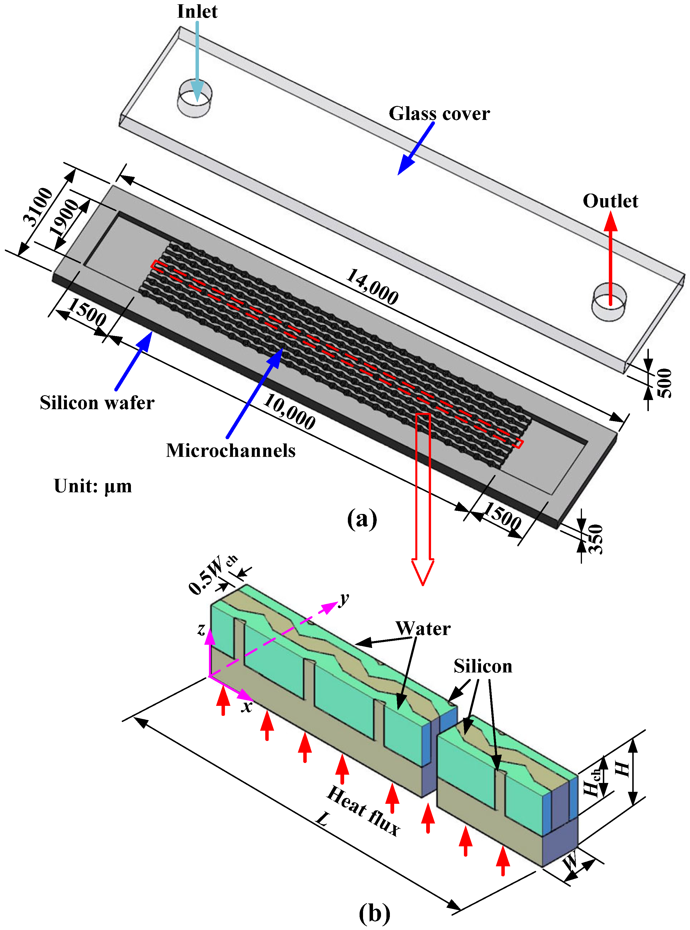
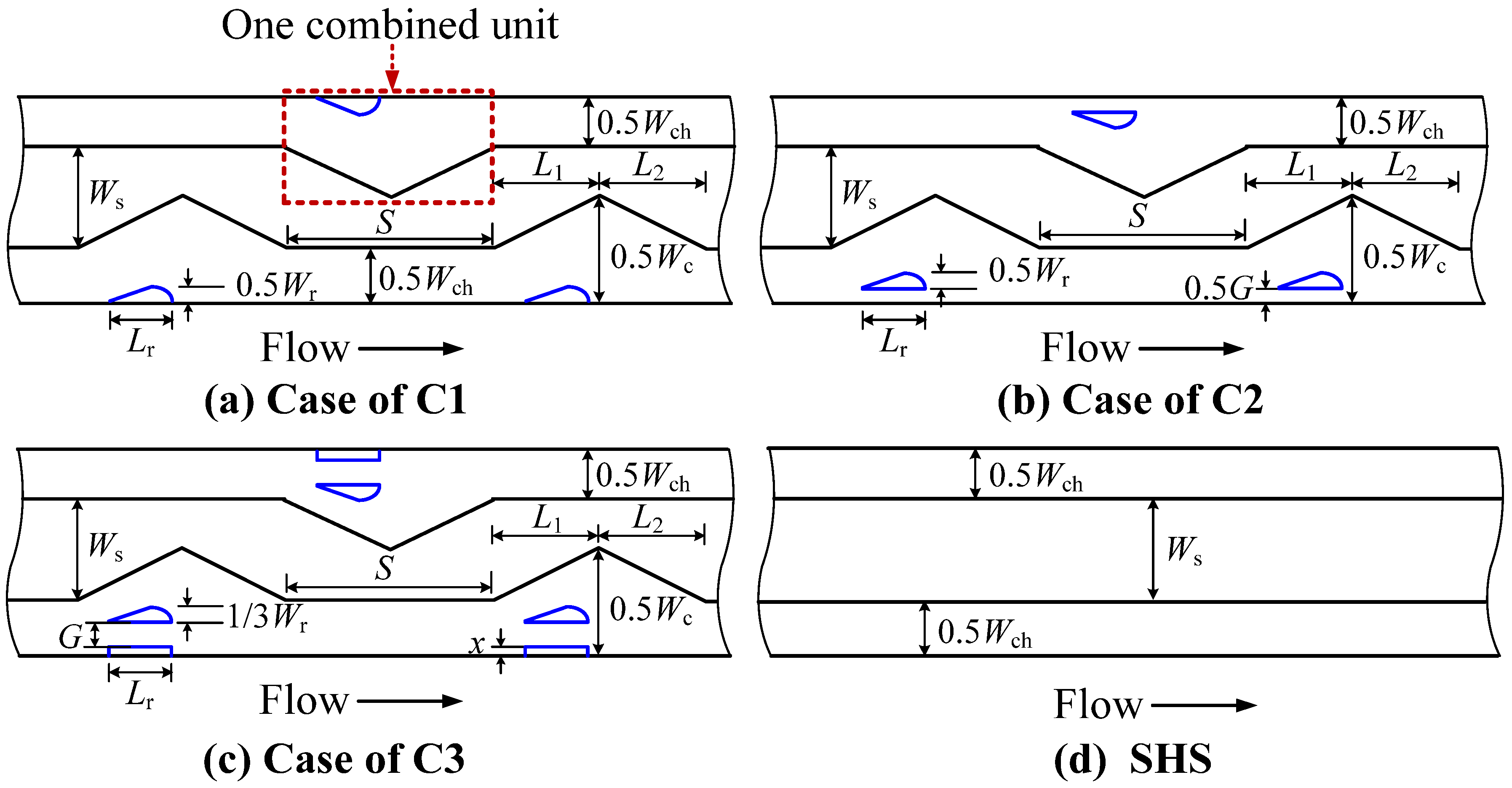
2.1. Configurations and Orthogonal Experiment

Figure 1 depicts the three-dimensional schematics of the MCHS and the computational model. As depicted in Figure 1a, silicon microchannels with triangular grooves and droplet-shaped fins were fabricated using ion etching technology. The heat-resistant glass is bonded with the silicon base by high-voltage static electricity. The platinum heating film is sputtered on the silicon to provide heat flux. Considering the symmetrical configuration of the microchannels, the computational model consists of the internal wall in the center and the half-channels on both sides, as described in Figure 1b. The length (L), width (Wch), and height (Hch) of the microchannel are 10 mm, 100 μm, and 200 μm.
The layout of the fins and local configurations are provided in Figure 2. One combined unit consists of the groove in the sidewall and the central fin, as marked by a red circle. The initial heat sink (IHS) contains 13 combined units in one microchannel, which are arranged uniformly along the flow direction. To explore the importance of the distribution and layout of the grooves and fins on the thermo-hydraulic features, a Taguchi analysis with three factors and three levels was conducted, as shown in Table 1. Factor A stands for the number of combined units (N), with three levels, 5, 13, and 21, which are discussed in this study.
Factor B represents the distribution of the combined units. The combined units are uniform distribution (B1), from sparse to dense (B2) and from dense to sparse (B3), respectively. For B1, the space between two grooves (S) is constant: (1) N = 5, S = 1933 μm; (2) N = 13, S = 568 μm; (3) N = 21, S = 268 μm. For B3, the space between grooves gradually increases as S1 = 200 μm + n, S2 = 200 μm + 2n, S3 = 200 μm + 3n, …, SN−1 = 200 μm + (N − 1)n: (1) N = 5, n = 624 μm; (2) N = 13, n = 54.4 μm; (3) N = 21, n = 6.3 μm. For B2, the variation rule of the space between grooves is inverse.
Factor C denotes the number of fins in one unit; three levels of one fin (C1), two fins (C2), and three fins (C3) are chosen. As plotted in Figure 2, for C2, the width and length of the droplet-shaped fin are consistent with the case of C1. Compared to the C1, the droplet-shaped fin is divided into two fins, and the gap between two fins (G) is 20 μm. For C3, the droplet-shaped fin is divided into three fins. The length of the droplet-shaped fin is consistent with C1, but the width becomes 10 μm. A streamlined fin with 60 μm in length and 10 μm in width is embedded in the middle of two droplet-shaped fins, which has a radius of 10 μm at the front edge and a radius of 20 μm at the trailing end. The gaps between the fins (G) are still maintained at 20 μm. Thus, the overall widths of the fins for C1, C2, and C3 are kept consistent to facilitate comparison, i.e., 30 μm. The local schematic of the smooth heat sink (SHS) is also presented in Figure 2. The specific sizes are listed in Table 2.

2.2. Governing Equation and Methodology

The range of flow velocities in this work corresponds to the Reynolds number of 174–634. The steady laminar flow and heat transport of the water in MCHSs were considered. The dynamic viscosity of water is sensitive to temperature, as shown in Table 3. In contrast, the other thermophysical parameters are unchanged within the temperature range considered in this work, as listed in Table 4. The thermophysical properties are aligned with our previous works [30,31]. At the micro-scale, the effect of gravity and other body forces is negligible.
Therefore, the equations for the incompressible laminar flow and convective heat transport in the MCHSs are expressed as follows:
Mass equation:
V = 0
Momentum equation:
ρ f V V = p + μ f 2 V
Energy equations:
ρ f c p , f V T f = λ f 2 T f               water
λ s 2 T s = 0                        silicon
The boundary conditions are listed in Table 5. The outlet pressure of the microchannel is atmospheric pressure, i.e., the relative pressure is 0 Pa. FLUENT software 6.3.26 is employed to conduct the numerical calculations. The specific method is consistent with the previous research [29,30,31]. The finite volume method was applied to solve the differential equations using a second-order upwind scheme. The SIMPLEC method was adopted to couple pressure and velocity. The residuals less than 10−6 were considered to be convergent.

3. Evaluation Index and Model Verification

3.1. Evaluation Index

The mean thermal resistance (Rave) was chosen to explain the thermal characteristics of diverse MCHSs, as defined by
R ave = T w , ave T f , i n q b A b m
The pump power was employed to evaluate the energy consumption of the cooling system, as defined by
P P = Δ p Q v
The flow rate of the whole heat sink is expressed as
Q v = m A in u in
The figure of merit (FOM) is widely applied to estimate the balance between the heat dissipation gain and pump power penalty [23,32,33], calculated using
F O M = R ave , 0 / R ave P P / P P 0 1 / 3
where 0 denotes the smooth heat sink (SHS) without roughness elements. For FOM > 1, the reduction in thermal resistance is larger than the increment of pump power, i.e., the liquid cooling system has a better cost performance.
To explore the essence of thermal enhancement, the field synergy theory was employed to elucidate the coupling effect of flow and temperature fields. The synergy angle β is calculated according to [20,34,35]:
β = arccos V T f | V | | T f |
The synergy angle β ranges from 0° to 90°. A smaller β is more conducive to enhancing heat transport. To further analyze the coupling effect between heat transport and hydrodynamic, the field synergy number (Fc) is calculated as follows [29,36]:
F c = N u R e P r
The Prandtl number Pr is related to fluid temperature, which is defined as
P r = ν a
The Nusselt number (Nu) and Reynolds number (Re) are defined as Equations (12) and (13), respectively.
N u ave = h ave D h λ f
R e = ρ f u in D h μ f
where the hydraulic diameter (Dh) and the mean heat transport coefficient (have) are obtained using Equations (14) and (15)
D h = 2 H ch W ch H ch + W ch
h ave = q b A b A con T w , ave T f , ave
A higher Fc indicates a larger Nu for the constant Re and Pr, indicating better thermal capability because of the superior coupling of the velocity field and temperature field.
The friction coefficient is calculated as
f ave = 2 Δ p D h ρ f L u in 2

3.2. Model Validation

The heat sink with thirteen combined units arranged uniformly, with one fin in each unit, was selected to confirm grid independence. GAMBIT software 2.4.6 was employed to establish the grids. Figure 3 presents the local enlarged plots of the 0.44 million, 0.75 million, and 1.07 million grids. A “Cooper”-type mesh was selected for grooves and fin domains to build unstructured grids because of their irregular shape. A “Map”-type mesh was chosen for the constant cross-section domains to form the structural grids. In general, the grid distribution was relatively uniform, showing periodic variations within the combined configurations.
Three models with 0.44 million mesh elements, 0.75 million mesh elements, and 1.07 million mesh elements were established. The Tw,ave and ΔP of different cases at uin = 3 m/s were examined. The relative errors of the cases with 0.44 million and 0.75 million mesh elements were compared to those of the case with 1.07 million mesh elements, as shown in Table 6. The errors in Tw,ave for the 0.44 million and 0.75 million mesh cases, compared to that of the 1.07 million mesh case, were very small. However, the error in ΔP for the 0.75 million mesh case (<3%) was smaller than that for the 0.44 million mesh case. Therefore, considering both thermal and hydraulic features, a mesh with 0.75 million elements was selected for numerical simulation. Other models were also verified for grid independence using the method above.
To examine the validity of the numerical model, the theoretical data of the Δp for SHS [37] and the temperature difference for IHS were calculated.
Δ p = K ρ f u in 2 8 + P o μ f u in L 2 D h 2
Δ T f = T f , out T f , in = q b A b ρ f A in u in c p , f
The Hagenbach factor (K) and Poiseuille number (Po) are given by the following equations:
K = 0.6796 + 1.2197 k + 3.3089 k 2 9.5921 k 3 + 8.9089 k 4 2.9959 k 5
P o = 96 1 1.3553 k + 1.9467 k 2 1.7012 k 3 + 0.9564 k 4 0.2537 k 5
As described in Figure 4a, the curve trend of the simulation results is consistent with that of the theoretical results. The maximum errors of the simulation and theoretical values for Δp and ΔTf are 9.96% and 2.96% at uin = 1 and 4.5 m/s, respectively. In addition, a numerical model consistent with the grooved heat sink in ref. [38] was established. The simulated results for Nu were compared with experimental results in ref. [38]. As plotted in Figure 4b, the simulated and experimental values exhibit the same variation trend. The maximum error is 5.47%, which is within the acceptable range. In consequence, the accuracy of the calculation method is verified.

4. Results and Discussion

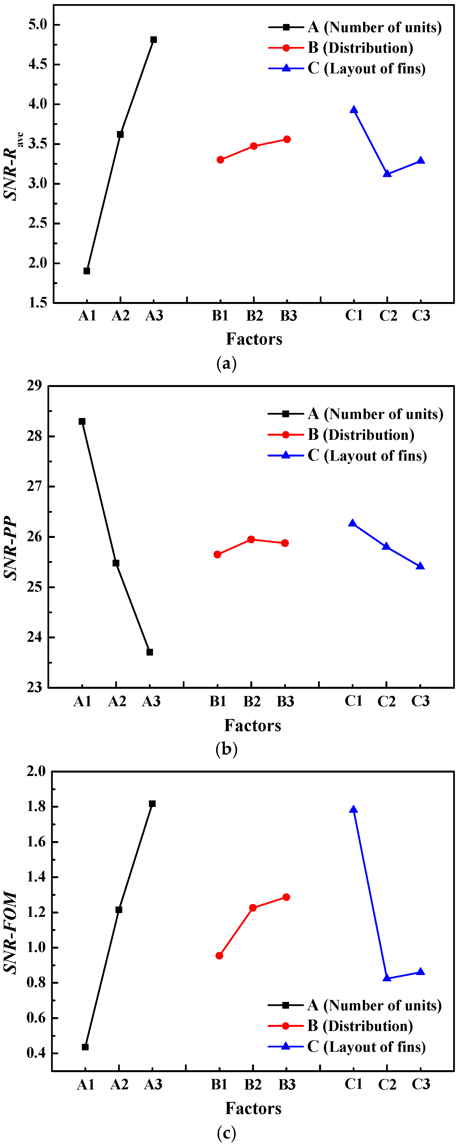
4.1. Taguchi Optimization

Thermal resistance, pump power, and FOM were selected for multi-objective optimization using the Taguchi method. The initial heat sink (IHS) consisted of thirteen uniformly arranged combined units, with one fin in each unit. The number of combined units, the distribution type of combined units, and the number of fins in one unit were chosen as optimization factors. Each factor had three levels, as displayed in Table 1. The importance of the aforementioned three factors on the thermal performance, power energy consumption, and overall efficiency of a cooling system can be determined quantitatively. Lower thermal resistance and pump power are expected to improve cooling capacity while maintaining acceptable energy consumption. Thus, the signal-to-noise ratio (SNR) is calculated by the following equation:
S N R 1 = 10 × lg 1 n i = 1 n Y i 2
The higher FOM indicates that the modified designs are beneficial for improving comprehensive capability. Hence, the SNR is calculated by the following equation:
S N R 2 = 10 × lg 1 n i = 1 n 1 Y i 2
The corresponding SNRs of thermal resistance, pump power, and FOM for each case are listed in Table 7. The SNRs for three targets are displayed in Figure 5. In Figure 5a, the SNRs of Rave increase with the number of combined units. The cooling effect is improved by a stronger disturbance. The SNR of Rave for the arrangement from dense to sparse is the highest, and that of the uniform arrangement is the lowest among the three layouts. For factor C, it was found that the layout with two fins in each unit exhibited the worst thermal performance, while the case with one fin achieved the best heat removal efficiency. The optimal combination is A3B3C1 for reducing thermal resistance.
The streamline and temperature distributions for the three fin layouts are depicted in Figure 6. We can observe that the case with one fin in each unit achieved the lowest temperature and the best uniformity. This is because of the main flow separation, acceleration, and periodic interruption on the boundary layers caused by the central fins. The blocking effect of central fins leads to strong impingement on the sidewalls, resulting in the highest heat transport rate. For the case with two fins, the gap between two fins weakens the disturbance effect, and the water flows over the fins through the gap. The lateral flow of coolant and chaotic mixing are weakened. Thus, the temperatures near the sidewalls are increased, and the temperature homogeneity is adversely affected. The heat removal of the case with three fins is better than that of the one with two fins. The reason is that the disturbance effect is strengthened due to the presence of the middle fins. As described in Figure 6, the temperature control capability of the case with C3 is superior to that of the case with C2, leading to relatively small thermal resistance.
As plotted in Figure 5b, the SNRs of PP exhibit an opposite trend compared to Rave for factor A. The increase in the number of micro-structures induces an obvious increment in pump energy consumption. The distribution type of the combined units has little effect on pump power compared to other factors. The distribution from sparse to dense shows a slight advantage compared to the other types. For factor C, increasing the number of fins results in a greater energy loss because of the increased friction losses. For pump power, the optimal parameter combination is A1B2C1.
As displayed in Figure 5c, the trend of the SNRs for the FOM is consistent with that of the thermal resistance, indicating that thermal performance contributes more significantly to overall efficiency. The optimal combination for enhancing overall efficiency is A3B3C1.
The mean SNRs and contribution ratios (CRs) for thermal resistance, pump power, and FOM are listed in Table 8, Table 9 and Table 10, respectively. The calculation method for CR is consistent with that in ref. [30], and it can estimate the importance and sensitivity of the factors with respect to the targets. A high CR signifies a greater impact. We can observe that the sensitivity level is A > C > B for thermal resistance, pump power, and FOM. The number of combined units is a crucial factor affecting heat transport, energy consumption, and overall efficiency, followed by the number of fins. The distribution pattern of combined units has the least influence.

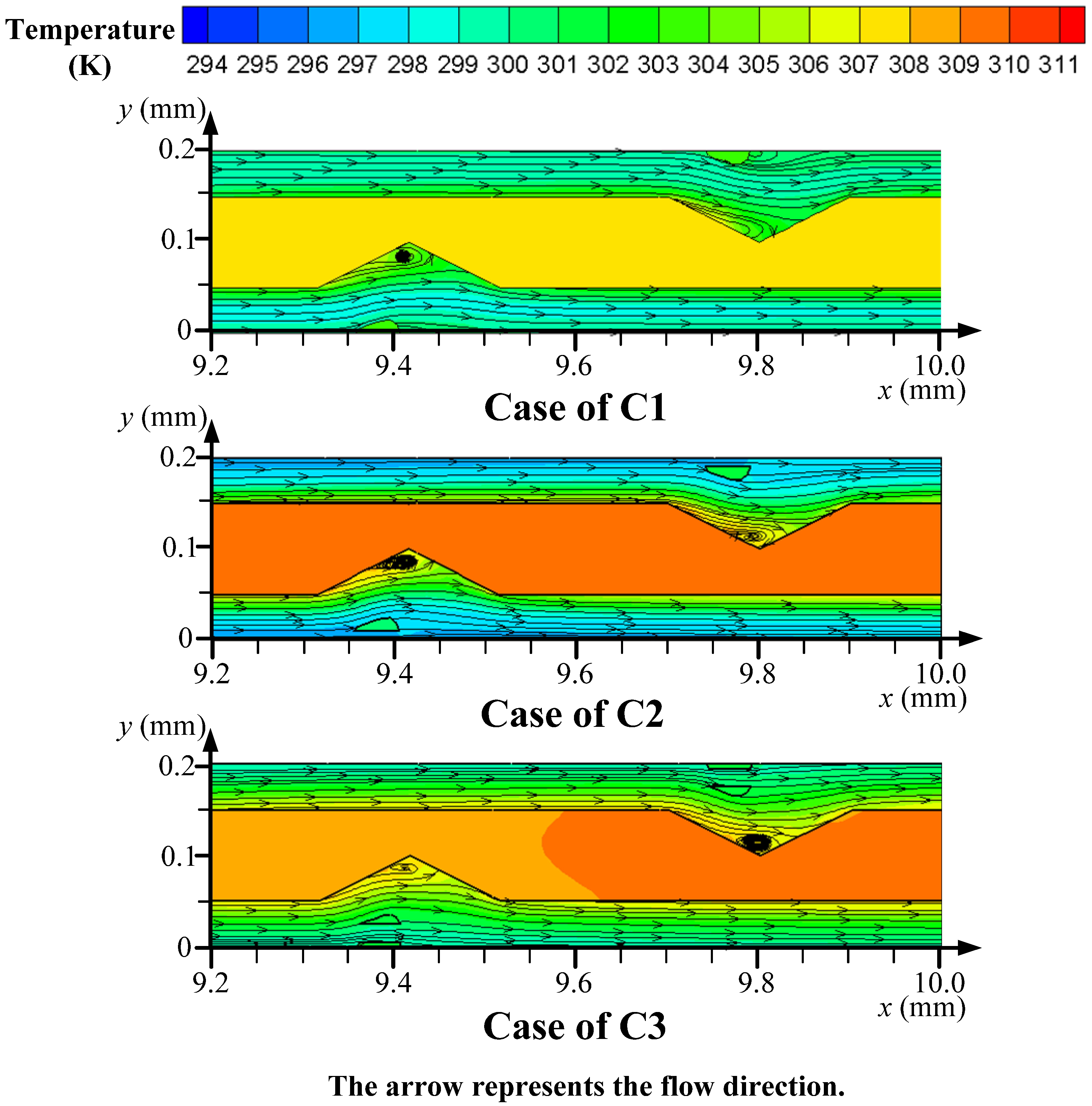
4.2. Thermo-Hydrodynamic Features

The optimal heat sink with A3B3C1 exhibits the best cooling capability and overall efficiency, called OHS-R. The optimal heat sink with A1B2C1 demonstrates the lowest pump power consumption, called OHS-PP. The thermo-hydraulic features of the two heat sinks described above are compared with those of the initial heat sink (IHS) before optimization and the smooth heat sink (SHS).
The temperature variation along the flow direction for various configurations is displayed in Figure 7. For the SHS, the temperature rise is the most drastic along the flow direction and reaches a peak near the outlet. The OHS-PP exhibits a higher temperature than the OHS-R and IHS. The temperature variation shows a trend of first increasing and then decreasing. This is related to the distribution pattern of the combined units. For OHS-PP, the combined units are arranged from sparse to dense. The increase in the number of grooves and fins downstream of the channel induces a stronger disturbance effect, which intensifies the mixing of hot/cold fluids and disrupts the boundary layers, thus enhancing heat transport near the outlet. The temperature control capability of the OHS-R is the best. At the channel outlet, the temperature on the silicon base of the OHS-R is reduced by 10.7 °C, 3.09 °C, and 1.61 °C compared to the SHS, OHS-PP, and IHS, respectively.
The streamline and temperature contours for four configurations are depicted in Figure 8. It is clear that for complex heat sinks, the effects of flow disturbance, separation, and acceleration lead to strong impingement on the silicon surface. On the xy planes, the chaotic mixing caused by the local vortexes in the IHS, OHS-R, and OHS-PP disrupts the boundary layer and reduces the temperatures of water and silicon compared to the traditional design. Moreover, symmetric vortexes are formed in the yz planes for the IHS, OHS-R, and OHS-PP. However, no vertex is formed in the xy and yz planes of the SHS. The OHS-R exhibits the lowest temperature, with the best uniformity. The thermal boundary layer of the OHS-R is thinner than the other heat sinks. For the yz planes of the IHS and OHS-R, when y < 0.1 mm, the cross-section is close to the groove, and no vortex is generated; when y > 0.1 mm, the cross-section is far away from the groove and symmetric vortexes are formed. For the OHS-PP, vortex pairs are formed in the channels on both sides of the silicon wall. In conclusion, the vortex pair can be formed in the z direction after the fluid flows out of the grooves for a certain distance. However, the relatively large space between the two combined units in the OHS-PP results in a thick boundary layer and a high temperature on the silicon wall. We can observe that the number of combined units, i.e., factor A, has an apparent impact on the flow and temperature patterns. The coolant can remove the heat more efficiently in the OHS-R because the number of combined units is greater than that in the other heat sinks.
The average temperature on the silicon base can directly reflect the heat dissipation capacity of heat sinks. As displayed in Figure 9, the average temperature of the four heat sinks gradually decreases with the increase in flow velocity. The traditional heat sink shows the worst cooling effect, followed by the OHS-PP, and then the IHS. The OHS-R shows the best heat removal performance, which is consistent with the Taguchi optimization. At uin = 4.5 m/s, the Tw,ave of the OHS-R is 7.44 °C, 4.41 °C, and 1.47 °C lower than that of the SHS, OHS-PP, and IHS, respectively, indicating more efficient heat removal from the electronic chip.
The ratios of thermal resistance (Rave,0/Rave) between the conventional heat sink (SHS) and the modified ones are plotted in Figure 10. A larger Rave,0/Rave indicates lower thermal resistance in the modified configurations. We can see that Rave,0/Rave is greater than one for all cases, indicating improved heat transport resulting from the inclusion of grooves and fins. As the flow velocity increases, Rave,0/Rave goes up because of the improved heat transport advantage by chaotic convection. We can find that the OHS-R heat sink achieves the highest Rave,0/Rave, i.e., the lowest Rave. The thermal resistance of the OHS-R is reduced by 45.57% compared to the SHS at uin = 4.5 m/s. The OHS-PP shows the smallest Rave,0/Rave, i.e., the largest Rave, because the optimization objective is to minimize energy consumption. Compared to the heat sinks IHS and OHS-PP, the thermal resistance of the OHS-R is reduced by 14.05% and 33.16% at uin = 4.5 m/s, demonstrating a cooling advantage.
The friction coefficients of various MCHSs are plotted in Figure 11. As the flow velocity increases, the friction coefficients show a downward trend. The flow rates of 1–4.5 m/s correspond to a Re of 174–634. The friction coefficient decreases with the increase in Re, confirming the laminar flow characteristic in the MCHSs. Within the parameter range of this work, the OHS-R shows the highest flow resistance as the cost of its heat transfer gain. The traditional SHS achieves the smallest friction coefficient because of the absence of vortexes and micro structures. Compared to the heat sink before optimization (IHS), the flow resistance of the OHS-PP is effectively reduced, with a maximum reduction of 27.61% at uin = 4.5 m/s (Re = 634).
The pump power ratios (PP/PP0) of different MCHSs are provided in Figure 12. The smaller ratio indicates the lower energy consumption of the cooling system. For the IHS and OHS-R, the pump energy consumption increases greatly with the increase of flow velocity, because of the increment of friction losses. After Taguchi optimization, the OHS-PP exhibits a relatively small increment of pump energy consumption within 1.39 at uin = 4.5 m/s. And the increment rate of pump power is also reduced compared to the IHS and OHS-R, indicating the energy saving advantage, especially for high flow velocity. At uin = 4.5 m/s, the energy consumption of OHS-PP is reduced by 41.29% and 27.61% compared to the OHS-R and IHS, confirming the optimization effect.
To examine the overall efficiency of optimal configurations, the variation in FOM is compared in Figure 13. It can be found that the overall efficiencies of all complex heat sinks are better than those of the smooth one, i.e., FOM > 1. As the flow velocity increases, the advantages of the comprehensive capability of complex heat sinks become more prominent. However, it is worth noting that the increment rate of overall efficiency for high velocity is lower than that for small velocity. As expected, the heat sink OHS-R exhibits the largest FOM of 1.38 at uin = 4.5 m/s, which is increased by 8.5% and 25.28% compared to the IHS and OHS-PP.

4.3. Field Synergy Analysis

Based on the field synergy theory, a smaller synergy angle (β) promotes better directional alignment between the velocity vector and the temperature gradient, leading to more efficient heat transport. The contours of the synergy angle β of four configurations are demonstrated in Figure 14. It can be observed that the triangular grooves and droplet-shaped fins significantly modify the interaction between the flow and temperature fields. At the groove corners and downstream of the fins, the vortexes induce a reduction in the synergy angle β, which is beneficial for increasing the heat transport rate. In addition, due to the flow separation impact of the fins, the lateral flow promotes the consistency between flow direction and temperature gradient upstream of the fins.
As displayed in Figure 15, the synergy angle β in the SHS is closer to 90°, owing to the lack of disturbance structures. For the heat sinks IHS, OHS-PP, and OHS-R, the β decreases as the flow velocity increases, due to intense chaotic mixing. The smallest β is achieved by the heat sink OHS-R. At uin = 4.5 m/s, the angle β of the OHS-R is 3.82° lower than that of the SHS. Because of the enhanced coupling effect of velocity and temperature fields, the water can remove more heat efficiently. This is the essential reason for the reduction in thermal resistance and the increase in heat transport.
To further reveal the coupling effect of flow and heat transport, the field synergy numbers (Fc) of different configurations are provided in Figure 16. For a fixed configuration, the Fc decreases with the increase in water velocity. According to Equation (10), as the velocity rises, the increment in Re exceeds the increment in Nu, leading to the downward trend in Fc. For a fixed velocity, the Re is invariable, and a high Nu results in a large Fc, indicating efficient heat transport. For the OHS-R, the velocity vector is most closely aligned with the temperature gradient, resulting in the highest heat transport rate. Therefore, the OHS-R exhibits the highest Fc, proving effective heat removal based on the inherent relation between the flow field and the temperature field.

5. Conclusions

Innovative heat sinks with triangular grooves and droplet-shaped fins were introduced to meet the cooling needs of high-power data centers (DCs). The sensitivity of the layout of the grooves and fins on thermo-hydrodynamic characteristics was explored, and the optimal designs were determined using Taguchi analysis. The cooling capability, thermal resistance, pump power, and overall efficiency were illustrated thoroughly. Moreover, the intrinsic mechanism behind the enhanced heat transport and the inherent relationship between velocity and temperature fields were clarified using the field synergy theory. The novel insights are listed as follows:
  • The number of combined units presents the greatest influence on thermal resistance, pump power, and overall efficiency, followed by the number of fins in each unit. For both thermal resistance and overall efficiency, the optimal configuration is the heat sink with 21 combined units, arranged from dense to sparse, with one fin in each unit (A3B3C1), which shows a 14.05% reduction in thermal resistance and a 8.5% increment in overall efficiency. For pump power, the optimal combination is the heat sink with five combined units, arranged from sparse to dense, with one fin in each unit (A1B2C1), which presents a 27.61% decrease in pump power.
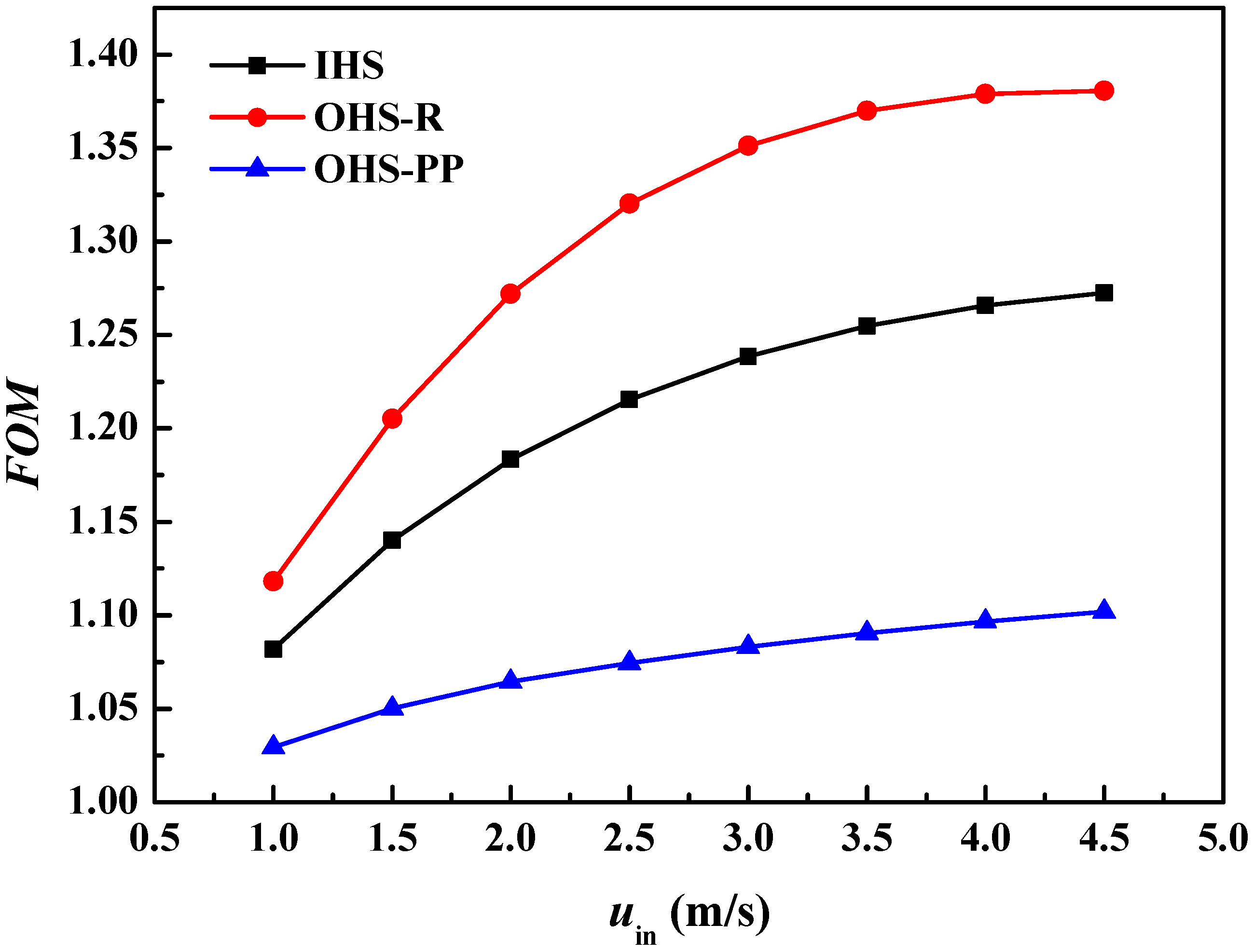
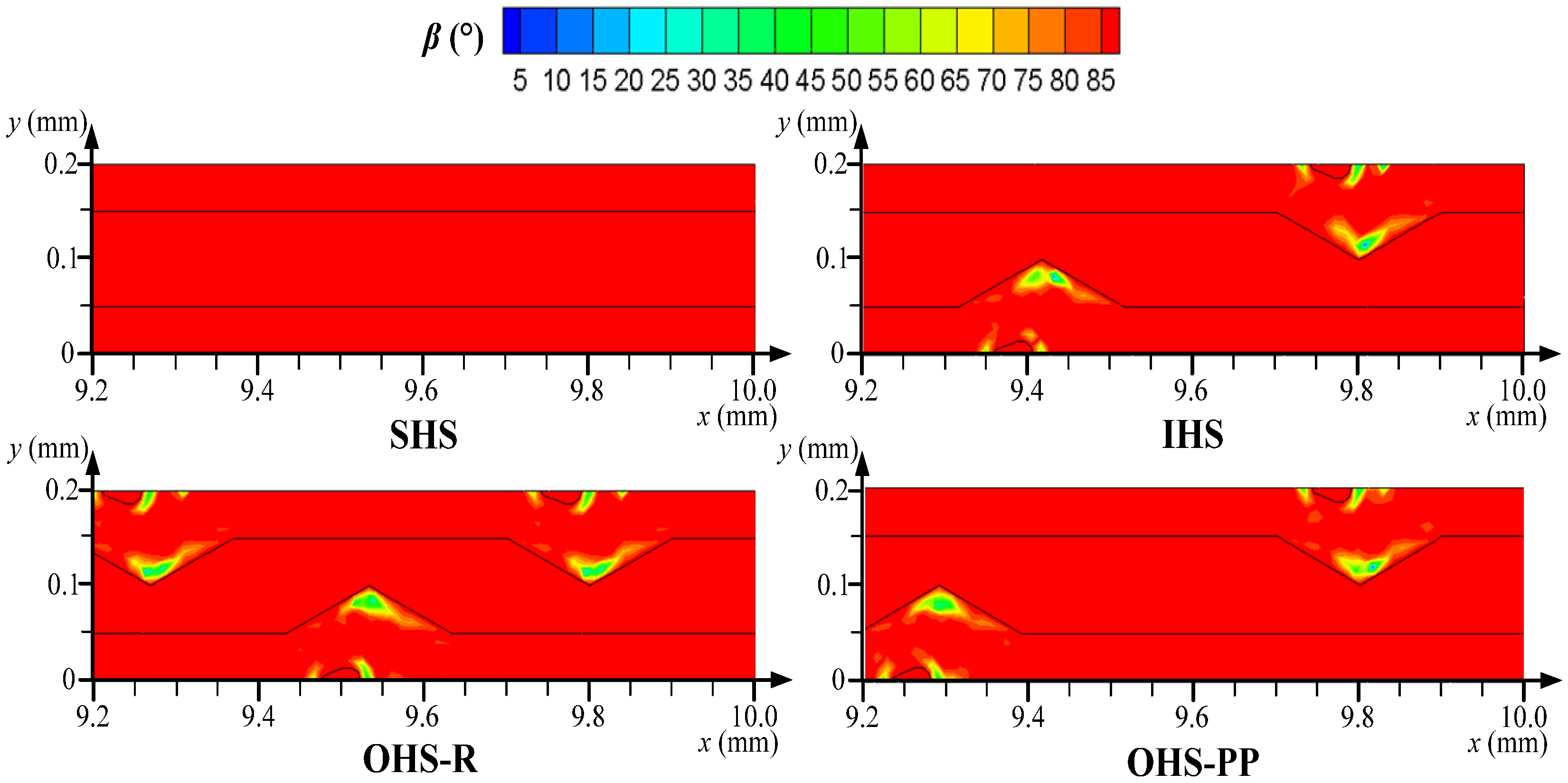
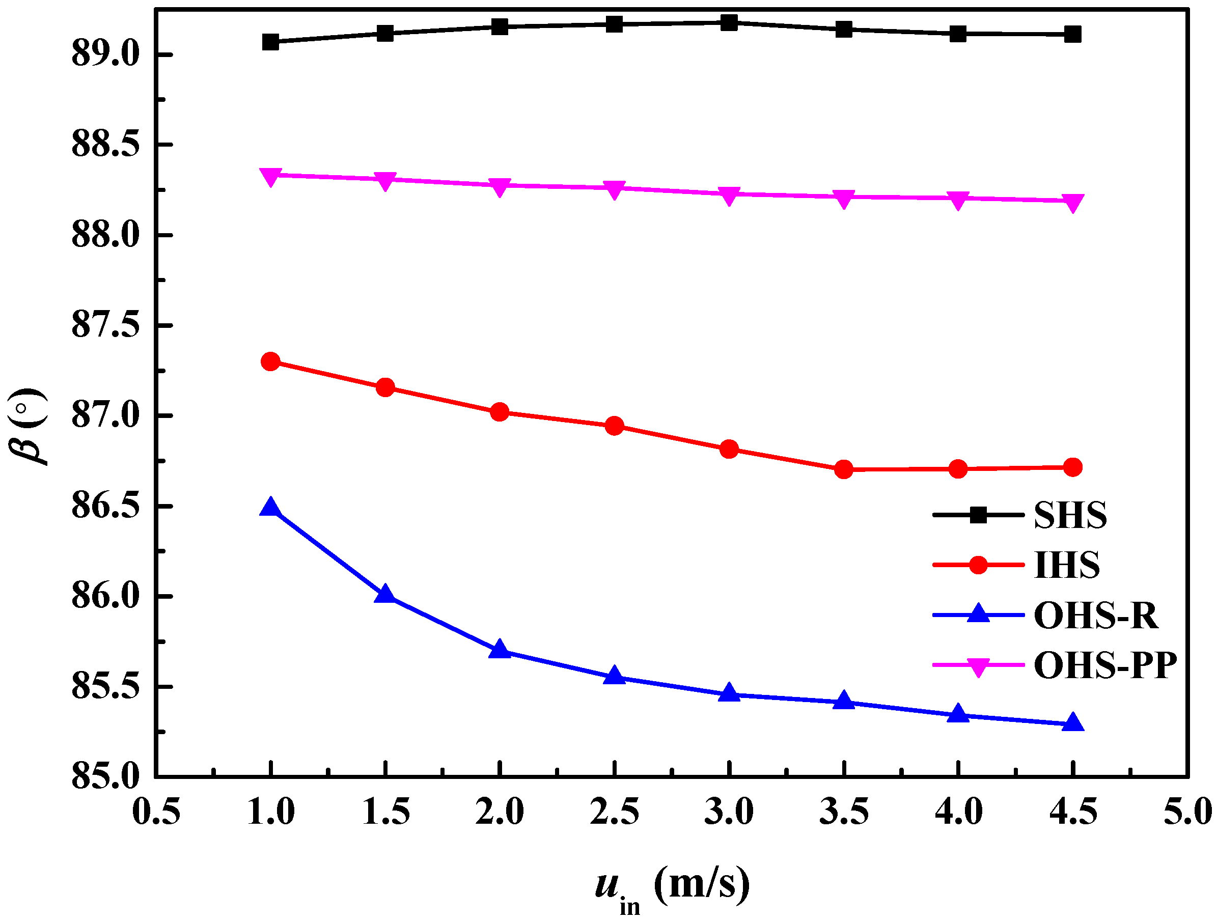
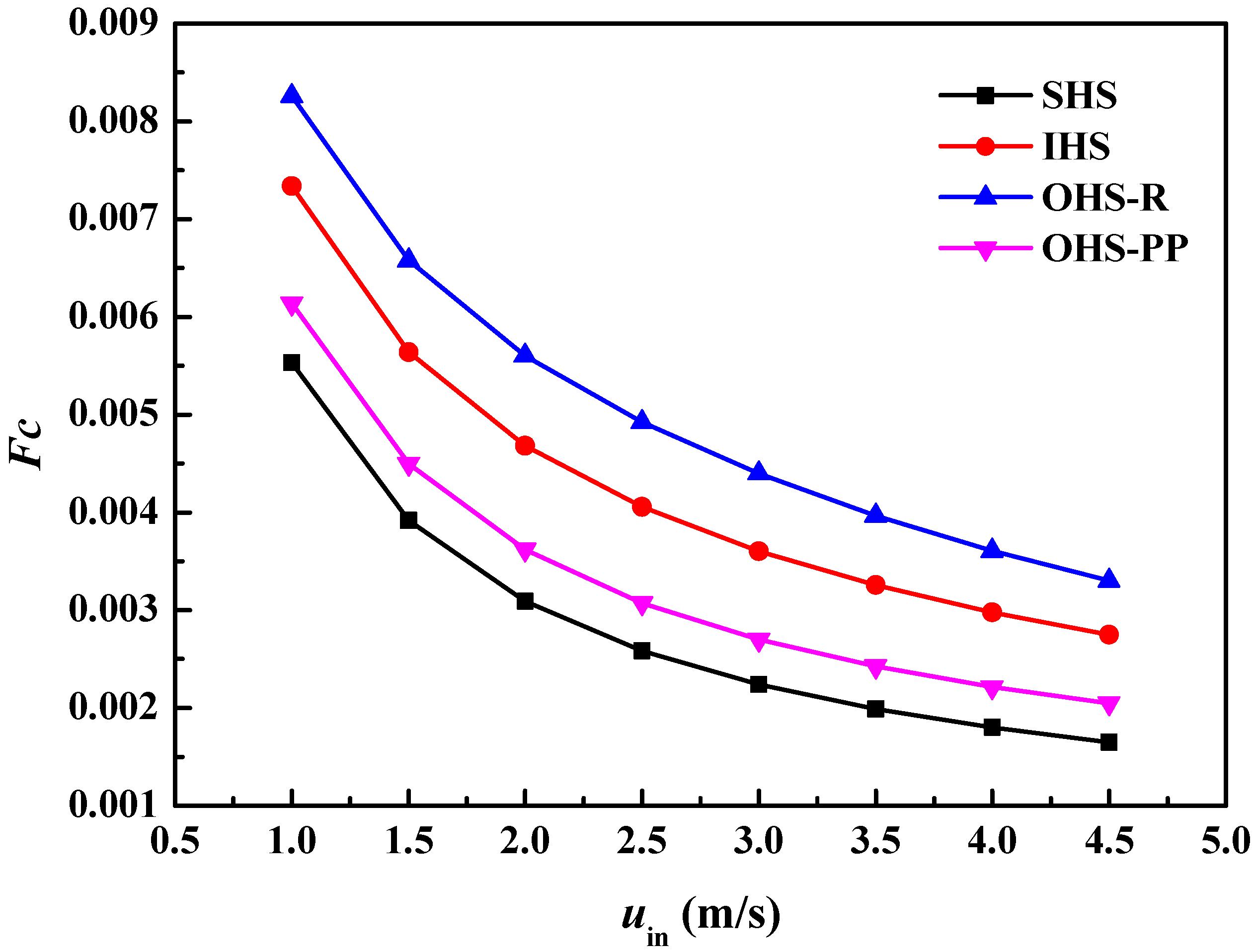
  • Compared to the cases with two or three fins in each unit, the single droplet-shaped fin presents superior thermal and hydrodynamic performances because of the enhanced impingement effect and reduced flow friction. The heat removal efficiency of the configuration A3B3C1 is improved because of the better coupling effect of flow and temperature fields with a 4.29% smaller synergy angle β compared to the smooth heat sink. Improving the coupling between the flow and temperature fields is beneficial for enhancing the cooling capability.
  • The optimized heat sinks can better balance heat dissipation and energy consumption, which can be applied to heat dissipation of high-power equipment in high-tech fields, e.g., DCs, power batteries, and energy conversion systems, to improve the cost-effectiveness of liquid cooling systems. In addition, the thermophysical properties of the coolant have a direct impact on the overall capability of the cooling systems. Further numerical and experimental studies will be conducted to explore the thermo-hydrodynamic features of novel coolants, e.g., nanofluids, CO2, phase change microcapsule suspension, etc. The cooling efficiency of this kind of heat sink under unsteady heat flux conditions and the intelligent regulation of cooling systems will be analyzed in detail to provide a theoretical basis for advanced thermal management.

Author Contributions

Writing—original draft preparation, L.Z.; formal analysis, J.S.; writing—review and editing, methodology, Y.L.; software, Z.W. All authors have read and agreed to the published version of the manuscript.

Funding

This research was funded by the Science and Technology Project of Tianjin (No. 24YDTPJC00680).

Data Availability Statement

The original contributions presented in this study are included in the article; further inquiries can be directed to the corresponding authors.

Conflicts of Interest

The authors declare no conflicts of interest. Author Y.L. was employed by the Tianjin Chengjian University. Author L.Z., J.S. and Z.W. were employed by the Tianjin Lantian Solar Technology Co., Ltd. The authors declare that the research was conducted in the absence of any commercial or financial relationships that could be construed as a potential conflict of interest.

Nomenclature

athermal diffusion coefficient [m2/s]
Aarea [m2]
cpspecific heat capacity [J/(kg·K)]
CRcontribution ratio [-]
Dhhydrodynamic diameter [m]
ffriction coefficient [-]
Fcfield synergy number [-]
FOMfigure of merit [-]
hheat transfer coefficient [W/(m2·K)]
Hchheight of microchannel [m]
kratio of channel width to height [-]
KHagenbach’s factor [-]
Llength [m]
Sspace between two grooves [m]
mnumber of parallel channel [-]
Nnumber of combined units [-]
NuNusselt number [-]
Δppressure drop [Pa]
PoPoiseuille number [-]
PPpump power [W]
PrPrandtl number [-]
qbheat flux per area [W/m2]
Qvflow rate [m3/s]
Rthermal resistance [K/W]
ReReynolds number [-]
SNRsignal-to-noise ratio [-]
Ttemperature [K]
uvelocity in x direction [m/s]
Vvelocity vector [m/s]
Wchwidth of microchannel [m]
Greek symbols
βsynergy angle [°]
λthermal conductivity [W/(m·K)]
μdynamic viscosity [Pa·s]
ρdensity [kg/m3]
νmomentum diffusion coefficient [m2/s]
Subscript
aveaverage
bbottom
conconvection
ffluid
ininlet
outoutlet
ssolid
wwall
0smooth heat sink

References

  1. Isazadeh, A.; Ziviani, D.; Claridge, D. Thermal management in legacy air-cooled data centers: An overview and perspectives. Renew. Sustain. Energy Rev. 2023, 187, 113707. [Google Scholar] [CrossRef]
  2. He, Z.Q.; Yan, Y.F.; Zhang, Z.E. Thermal management and temperature uniformity enhancement of electronic devices by micro heat sinks: A review. Energy 2021, 216, 119223. [Google Scholar] [CrossRef]
  3. Li, Z.Y.; Luo, H.L.; Jiang, Y.G.; Liu, H.; Xu, L.; Cao, K.; Wu, H.; Gao, P.; Liu, H. Comprehensive review and future prospects on chip-scale thermal management: Core of data center’s thermal management. Appl. Therm. Eng. 2024, 251, 123612. [Google Scholar] [CrossRef]
  4. Pan, M.Q.; Wang, H.Q.; Zhong, Y.J.; Hu, M.; Zhou, X.; Dong, G.; Huang, P. Experimental investigation of the heat transfer performance of microchannel heat exchangers with fan-shaped cavities. Int. J. Heat Mass Transf. 2019, 134, 1199–1208. [Google Scholar] [CrossRef]
  5. Alfellag, M.A.; Ahmed, H.E.; Fadhil, O.T.; Kherbeet, A.S. Optimal hydrothermal design of microchannel heat sink using trapezoidal cavities and solid/slotted oval pins. Appl. Therm. Eng. 2019, 158, 113765. [Google Scholar] [CrossRef]
  6. Sun, L.; Li, J.; Hu, H.; Ma, J.; Peng, H. Numerical study on heat transfer and flow characteristics of novel microchannel heat sinks. Int. J. Therm. Sci. 2022, 176, 107535. [Google Scholar] [CrossRef]
  7. Fathi, M.; Heyhat, M.M.; Targhi, M.Z.; Emadi, A. Semi-porous-fin microchannel heat sinks for enhanced micro-electronics cooling. Int. Commun. Heat Mass Transf. 2024, 157, 107814. [Google Scholar] [CrossRef]
  8. Cui, H.C.; Fan, W.H.; Wang, J.; Yu, M.J.; Zhang, Z.K.; Liu, Z.C.; Liu, W. Characteristics analysis and structure optimization of a hybrid micro-jet impingement/micro-channel heat sink. Appl. Therm. Eng. 2024, 245, 122769. [Google Scholar] [CrossRef]
  9. Chen, S.J.; Li, S.W.; Hu, Z.Z. Fluid flow and heat transfer characteristics of manifold microchannel heat sinks with ribs of different shapes. Int. J. Heat Mass Transf. 2025, 251, 127300. [Google Scholar] [CrossRef]
  10. Bhandari, P. Numerical investigations on the effect of multi-dimensional stepness in open micro pin fin heat sink using single phase liquid fluid flow. Int. Commun. Heat Mass Transf. 2022, 138, 106392. [Google Scholar] [CrossRef]
  11. Wang, S.S.; Xia, G.D.; Ma, D.D. Thermal-hydraulic performance in novel microchannels with asymmetric cavities and coaxially variable-size water droplet ribs. Int. Commun. Heat Mass Transf. 2024, 159, 108032. [Google Scholar] [CrossRef]
  12. Liu, L.Y.; Liu, H.T.; Luo, J.; Tang, J. Thermal-hydraulic performance of an imperfectly bonded ultrathin manifold micro pin-fin channel heat sink. Int. Commun. Heat Mass Transf. 2024, 156, 107684. [Google Scholar] [CrossRef]
  13. Sahel, D.; Boudaoud, W.; Bouabidi, A.; Alem, K. Impact of splitter inserts combined with perforation technique and transversal fins on the performance of micro pin heat sinks. Int. Commun. Heat Mass Transf. 2024, 159, 108094. [Google Scholar] [CrossRef]
  14. Xue, Z.G.; Yan, Y.F.; Shen, K.M.; You, J.; Zhang, C.; He, Z. Investigation on thermal-hydraulic performance for local hotspot via variable density design of a micro-jet heat sink. Int. Commun. Heat Mass Transf. 2024, 156, 107668. [Google Scholar] [CrossRef]
  15. Zhou, J.H.; Lu, M.X.; Han, L.; Zhao, Q.; Li, Q.; Chen, X. Topological manifold microchannel cooling for thermal management of divertor in fusion reactor. Energy 2025, 315, 134145. [Google Scholar] [CrossRef]
  16. Liu, Z.X.; Han, Q.; Han, J.W.; Zhang, Y.; Chen, X.; Li, W. Flow boiling in a relatively large copper heat sink comprised of Tesla microchannels. Int. J. Heat Mass Transf. 2025, 236, 126366. [Google Scholar] [CrossRef]
  17. Ma, D.D.; Liu, Y.S.; Zhang, X.M.; Xia, G. Experimental and numerical investigation of the thermohydraulic performance of a variable-period sinusoidal microchannel heat sink. Appl. Therm. Eng. 2025, 262, 125234. [Google Scholar] [CrossRef]
  18. Wang, Z.X.; Tao, W.Q. Heat transfer and pressure drop characteristics of microchannel cold plate in commercial CPU-package cooling system. Int. J. Heat Mass Transf. 2025, 246, 127060. [Google Scholar] [CrossRef]
  19. Song, H.L.; Han, B.; Wang, Y.; Zhang, Q. Enhanced heat transfer of alveolar biomimetic interlaced hollow lattice metastructures. Energy 2025, 326, 136272. [Google Scholar] [CrossRef]
  20. Guo, Z.Y.; Li, D.Y.; Wang, B.X. A novel concept for convective heat transfer enhancement. Int. J. Heat Mass Transf. 1998, 41, 2221–2225. [Google Scholar] [CrossRef]
  21. Yao, P.T.; Zhai, Y.L.; Li, Z.H.; Shen, X.; Wang, H. Thermal performance analysis of multi-objective optimized microchannels with triangular cavity and rib based on field synergy principle. Case Stud. Therm. Eng. 2021, 25, 100963. [Google Scholar]
  22. Mukherjee, A.; Senapati, J.R.; Barik, A.K. Field synergy and thermodynamic evaluation of a mini-duct with several protrusions utilizing the cross-flow method: A numerical exercise. Int. Commun. Heat Mass Transf. 2023, 145, 106817. [Google Scholar] [CrossRef]
  23. Bazkhane, S.; Zahmatkesh, I. Taguchi–based sensitivity analysis of hydrodynamics and heat transfer of nanofluids in a microchannel heat sink (MCHS) having porous substrates. Int. Commun. Heat Mass Transf. 2020, 118, 104885. [Google Scholar] [CrossRef]
  24. Huang, S.; Li, J.Q.; Zhu, K.; Dong, J.; Jiang, Y. Multifactor optimization of medium and deep U-type borehole heat exchanger design using Taguchi method. Geothermics 2023, 109, 102644. [Google Scholar] [CrossRef]
  25. Shi, Z.R.; Lan, X.; Cao, J.; Zhao, N.; Cheng, Y. Numerical study of variable density and height flow guided pin fin in an open microchannel heat sink. Int. J. Heat Mass Transf. 2024, 225, 125405. [Google Scholar] [CrossRef]
  26. Tang, Z.G.; Yin, C.; Xiang, Y.; Yu, P.; Cheng, J. Multi-objective optimization of a hybrid nanofluid jet impinging on a microchannel heat sink with semi-airfoil ribs based on field synergy principle. Int. J. Heat Mass Transf. 2024, 225, 125431. [Google Scholar] [CrossRef]
  27. He, W.; Wang, Z.X.; Li, J.Q.; Li, Q. Investigation of heat transfer performance for through-silicon via embedded in micro pin fins in 3D integrated chips. Int. J. Heat Mass Transf. 2023, 214, 124442. [Google Scholar] [CrossRef]
  28. Jia, Y.T.; Xia, G.D.; Li, Y.F.; Ma, D.; Cai, B. Heat transfer and fluid flow characteristics of combined microchannel with cone-shaped micro pin fins. Int. Commun. Heat Mass Transf. 2018, 92, 78–89. [Google Scholar] [CrossRef]
  29. Li, Y.F.; Wang, Z.P.; Yang, J.L.; Liu, H. Thermal and hydraulic characteristics of microchannel heat sinks with cavities and fins based on field synergy and thermodynamic analysis. Appl. Therm. Eng. 2020, 175, 115348. [Google Scholar] [CrossRef]
  30. Li, Y.F.; Wang, T.Y.; Wang, Z.P.; Yang, J.; Cao, W.; Ma, X. Thermohydraulic performance analysis and parameters optimization of the combined heat sinks with microchannels and micro pin-fins. Appl. Therm. Eng. 2024, 241, 122443. [Google Scholar] [CrossRef]
  31. Li, Y.F.; Yang, B.; Wang, Z.P.; Guo, Q. Investigation on the thermal and hydraulic characteristics of the micro heat sinks with grooves and pin fins by Taguchi-based sensitivity analysis. Appl. Therm. Eng. 2024, 249, 123454. [Google Scholar] [CrossRef]
  32. Al-Rashed, A.; Shahsavar, A.; Rasooli, O.; Moghimi, M.A.; Karimipour, A.; Tran, M.D. Numerical assessment into the hydrothermal and entropy generation characteristics of biological water–silver nano–fluid in a wavy walled microchannel heat sink. Int. Commun. Heat Mass Transf. 2019, 104, 118–126. [Google Scholar] [CrossRef]
  33. Ho, C.J.; Peng, J.K.; Yang, T.F.; Rashidi, S.; Yan, W.-M. Comparison of cooling performance of nanofluid flows in mini/micro-channel stacked double-layer heat sink and single-layer micro-channel heat sink. Int. J. Therm. Sci. 2023, 191, 108375. [Google Scholar] [CrossRef]
  34. Bi, C.; Tang, G.H.; Tao, W.Q. Heat transfer enhancement in mini-channel heat sinks with dimples and cylindrical grooves. Appl. Therm. Eng. 2013, 55, 121–132. [Google Scholar] [CrossRef]
  35. Zhai, Y.L.; Xia, G.D.; Liu, X.F.; Li, Y.F. Heat transfer in the microchannels with fan-shaped reentrant cavities and different ribs based on field synergy principle and entropy generation analysis. Int. J. Heat Mass Transf. 2014, 68, 224–233. [Google Scholar] [CrossRef]
  36. Guo, J.F.; Xu, M.T.; Cheng, L. Second law analysis of curved rectangular channel. Int. J. Therm. Sci. 2011, 50, 760–768. [Google Scholar] [CrossRef]
  37. Steinke, M.E.; Kandlikar, S.G. Single-phase liquid friction factors in microchannels. Int. J. Therm. Sci. 2006, 45, 1073–1083. [Google Scholar] [CrossRef]
  38. Chai, L.; Xia, G.D.; Wang, L.; Zhou, M.; Cui, Z. Heat transfer enhancement in microchannel heat sinks with periodic expansion-constriction cross-sections. Int. J. Heat Mass Transf. 2013, 62, 741–751. [Google Scholar] [CrossRef]
Figure 1. Schematics of (a) the silicon heat sink and (b) the computational model.
Energies 18 03396 g001
Figure 2. The layout and local configuration of different heat sinks.
Energies 18 03396 g002
Figure 3. The local enlarged plots of the grid structure (z = 0.25 mm).
Energies 18 03396 g003
Figure 4. Comparison of numerical data with (a) the theoretical data and (b) experimental data [38].
Energies 18 03396 g004
Figure 5. Average SNRs of (a) Rave, (b) PP, and (c) FOM.
Energies 18 03396 g005
Figure 6. Distributions of streamline and temperature for different fin configurations at uin = 3 m/s in the xy planes (z = 0.25 mm).
Energies 18 03396 g006
Figure 7. Evolution of local silicon temperature along the x-direction for uin = 3 m/s.
Energies 18 03396 g007
Figure 8. Distributions of streamline and temperature for four structures at uin = 3 m/s in the xy planes (z = 0.25 mm) and yz planes (x = 9.6 mm).
Energies 18 03396 g008
Figure 9. Mean temperature on the heating surface for various configurations.
Energies 18 03396 g009
Figure 10. The Rave,0/Rave versus uin of different MCHSs.
Energies 18 03396 g010
Figure 11. The friction coefficient versus uin of different MCHSs.
Energies 18 03396 g011
Figure 12. The PP/PP0 versus uin of different MCHSs.
Energies 18 03396 g012
Figure 13. The FOM versus uin of varying heat sinks.
Energies 18 03396 g013
Figure 14. Distributions of synergy angle β for four structures at uin = 3 m/s in the xy planes (z = 0.25 mm).
Energies 18 03396 g014
Figure 15. Synergy angle β versus velocity for various configurations.
Energies 18 03396 g015
Figure 16. Fc versus uin for different configurations.
Energies 18 03396 g016
Table 1. Orthogonal experiment of Taguchi analysis.
Case Design Factors
A
(Number of Combined
Units, N)
B
(Distribution of
Combined Units)
C
(Number of Fins
in Each Unit)
11 (N = 5)1 (uniform distribution)1 (one fin)
21 (N = 5)2 (from sparse to dense)2 (two fins)
31 (N = 5)3 (from dense to sparse)3 (three fins)
42 (N = 13)1 (uniform distribution)2 (two fins)
52 (N = 13)2 (from sparse to dense)3 (three fins)
62 (N = 13)3 (from dense to sparse)1 (one fin)
73 (N = 21)1 (uniform distribution)3 (three fins)
83 (N = 21)2 (from sparse to dense)1 (one fin)
93 (N = 21)3 (from dense to sparse)2 (two fins)
Table 2. Geometric sizes of the proposed configuration.
SymbolSize (μm)SymbolSize (μm)SymbolSize (μm)
G20L2100Wr30
H350Lr60Ws100
Hch200W200x5
L10,000Wc200
L1100Wch100
Table 3. Dynamic viscosity of water.
T (K)μf × 106 (Pa·s)
2931004.0
303801.5
313653.3
323549.4
333469.9
343406.1
353355.1
363314.9
Table 4. Constant thermophysical parameters independent of temperature.
ParametersSiliconWater
cp (J/(kg·K))7124183
ρ (kg/m3)2329998.2
λ (W/(m·K))1480.6002
Table 5. Boundary conditions.
LocationValue
Velocity inlet (uin, Tin)1~4.5 m/s, 293 K
Pressure outlet (pout)Pout = 0 Pa (relative pressure)
Heat flux at the heating film (qb)106 W/m2
Two sides of the computational modelSymmetry
Water–silicon interfaceCoupled without slip
Other surfacesAdiabatic
Table 6. Results of different cases compared to those of the 1.07 million mesh case.
MeshTw,ave (K)ΔP (Pa)
0.44 million0.133%4.98%
0.75 million0.13%1.73%
Table 7. Objectives and corresponding SNRs.
CaseRave (K/W)SNR-RavePP (W)SNR-PPFOMSNR-FOM
10.782.20 0.0428.46 1.100.79
20.831.62 0.0428.36 1.020.18
30.811.88 0.0428.06 1.040.34
40.693.18 0.0525.40 1.090.75
50.673.45 0.0625.09 1.110.92
60.614.23 0.0525.93 1.261.98
70.594.53 0.0723.08 1.161.33
80.545.35 0.0624.39 1.352.58
90.594.56 0.0723.64 1.191.55
Table 8. The SNRave for thermal resistance.
LevelA
(Number of
Combined Units, N)
B
(Distribution of
Combined Units)
C
(Number of Fins in Each Unit)
11.903.303.93
23.623.473.12
34.8123.563.29
Contribution ratio73.276.4720.25
Rank132
Table 9. The SNRave for pump power.
LevelA
(Number of
Combined Units, N)
B
(Distribution of
Combined Units)
C
(Number of Fins in Each Unit)
128.2925.6526.26
225.4825.9525.80
323.7125.8825.41
Contribution ratio79.97 5.19 14.84
Rank1 32
Table 10. The SNRave for FOM.
LevelA
(Number of
Combined Units, N)
B
(Distribution of
Combined Units)
C
(Number of Fins in Each Unit)
10.440.951.78
21.211.230.82
31.821.290.86
Contribution ratio51.7112.44 35.85
Rank1 32
Disclaimer/Publisher’s Note: The statements, opinions and data contained in all publications are solely those of the individual author(s) and contributor(s) and not of MDPI and/or the editor(s). MDPI and/or the editor(s) disclaim responsibility for any injury to people or property resulting from any ideas, methods, instructions or products referred to in the content.

