Article

Centrifugal Pumping Force in Oil Injection-Based TMS to Cool High-Power Aircraft Electric Motors

by
Giuseppe Di Lorenzo
*,
Diego Giuseppe Romano
*,
Antonio Carozza
and
Antonio Pagano
CIRA—Italian Aerospace Research Center, Via Maiorise SNC, 81043 Capua, CE, Italy
*
Authors to whom correspondence should be addressed.
Energies 2025, 18(13), 3390; https://doi.org/10.3390/en18133390
Submission received: 30 May 2025 / Revised: 13 June 2025 / Accepted: 19 June 2025 / Published: 27 June 2025
(This article belongs to the Special Issue Power Electronics Technology and Application)

Abstract

One of the challenges of our age is climate change and the ways in which it affects the Earth’s global ecosystem. To face the problems linked to such an issue, the international community has defined actions aimed at the reduction in greenhouse gas emissions in several sectors, including the aviation industry, which has been requested to mitigate its environmental impact. Conventional aircraft propulsion systems depend on fossil fuels, significantly contributing to global carbon emissions. For this reason, innovative propulsion technologies are needed to reduce aviation’s impact on the environment. Electric propulsion has emerged as a promising solution among the several innovative technologies introduced to face climate change challenges. It offers, in fact, a pathway to more sustainable air travel by eliminating direct greenhouse gas emissions, enhancing energy efficiency. Unfortunately, integrating electric motors into aircraft is currently a big challenge, primarily due to thermal management-related issues. Efficient heat dissipation is crucial to maintain optimal performance, reliability, and safety of the electric motor, but aeronautic applications are highly demanding in terms of power, so ad hoc Thermal Management Systems (TMSs) must be developed. The present paper explores the design and optimization of a TMS tailored for a megawatt electric motor in aviation, suitable for regional aircraft (~80 pax). The proposed system relies on coolant oil injected through a hollow shaft and radial tubes to directly reach hot spots and ensure effective heat distribution inside the permanent magnet cavity. The goal of this paper is to demonstrate how advanced TMS strategies can enhance operational efficiency and extend the lifespan of electric motors for aeronautic applications. The effectiveness of the radial tube configuration is assessed by means of advanced Computational Fluid Dynamics (CFD) analysis with the aim of verifying that the proposed design is able to maintain system thermal stability and prevent its overheating.

1. Introduction

The 21st Conference of the parties (COP21) to the United Nations Framework Convention on Climate Change (UNFCCC) took place in Paris, France, from 30 November to 12 December 2015, when the so-called Paris Agreement was adopted. This agreement is a legally binding international treaty aiming to limit global warming to below 2 °C, ideally under 1.5 °C, above pre-industrial levels by reducing greenhouse gas emissions. The agreement was signed by 195 countries and ratified by 193, and each country sets its own Nationally Determined Contributions (NDCs) to reduce emissions and reports progress regularly [1,2,3].
Due to the adoption of the Paris Agreement, several sectors of industry (including aviation) are implementing new actions to reduce their carbon footprint, with the aim of reducing the increase in average world temperature, meeting overall targets imposed by International Organizations. With reference to the aeronautic sector, the Long-Term Aspiration Goal (LTAG) was introduced by the International Civil Aviation Organization (ICAO), aiming for net-zero carbon emissions by 2025 [4].
Subsequently, the International Airlines Group (IAG) has defined the Flightpath Net Zero initiative to support the broader objective of limiting global warming to 1.5 °C above pre-industrial levels, by committing to net-zero carbon emissions by 2050 [4,5]. IAG’s strategy includes six highly impactful approaches: Sustainable Aviation Fuels (SAFs), which is a crucial component in reducing aviation emissions (airlines are investing in biofuels and synthetic fuels that significantly lower carbon footprints compared to conventional jet fuel) [6]; aircraft technology advancements (manufacturers are developing more efficient aircraft with improved aerodynamics, lighter materials, and advanced propulsion systems, including electric and hydrogen-powered aircraft) [6,7]; operational efficiency improvements (airlines are optimizing flight routes, improving air traffic management, and adopting fuel-saving techniques such as single-engine taxiing and continuous descent approaches) [8]; carbon offsetting and reduction schemes (programs like CORSIA—Carbon Offsetting and Reduction Scheme for International Aviation) help airlines compensate for emissions by investing in carbon reduction projects) [9]; infrastructure and energy transition (airports and aviation hubs are transitioning to renewable energy sources, improving ground operations efficiency, and supporting SAF production and distribution) [6]; and policy and financial support (governments and international organizations are implementing regulations, incentives, and funding mechanisms to accelerate the adoption of sustainable aviation technologies) [6].
In January 2025, the European Union Aviation Safety Agency (EASA) published the European Aviation Environmental Report 2025, which outlines progress and future strategies for emissions reduction in aviation [10].
Among the above-reported strategies, the research summarized in this paper focuses on the hybrid-electric propulsion, one of the most promising approaches. Such power units face stringent thermal constraints that conventional cooling technologies used in modern aircraft cannot effectively address. This challenge comes from the limited thermal properties (e.g., inadequate heat transfer capacity) of traditional coolants (air, lubricants, water, etc.), as well as additional restrictions related to size, weight, and thermal management requirements. Consequently, extensive research is being conducted to develop innovative cooling technologies that can ensure the safe and efficient operation of hybrid propulsion systems. The present work is an example of the current efforts to design an innovative TMS to guarantee safe operations of a MW electric motor designed for regional aircraft.
Within the European Research Initiative Optimised Electric Network Architectures and Systems for More-Electric Aircraft (ORCHESTRA) [11], the Italian Aerospace Research Centre (CIRA) has developed a TMS based on impinging jets technology for a 1 MW electric motor, fully described in [12]. TMS is also one of the most relevant topics of ELECTROPLANE, a project that CIRA is conducting under the umbrella of the Italian Aerospace Research Program, PRO.R.A., funded by the Italian Ministry of University and Research [13]. ELECTROPLANE, launched to explore the key technologies enabling the adoption of hybrid electric propulsion systems for regional aircraft, has already enriched the investigations on the TMS developed in [12] by considering nanoparticles in the base fluid [14]. The topic is further expanded in the ELECTROPLANE project by developing an advanced cooling architecture, which is the focus of the present article.
In practice, the cooling oil is also conveyed towards the hollow crankshaft containing a medial area where there are holes from which radial tubes depart and through which the oil is forced to pass by the action of centrifugal force. The radial tubes carry the oil directly into the air gap, thus cooling the area that is most difficult to reach with other cooling techniques.
This TMS architecture is extensively explored in this work, demonstrating its high potential and effectiveness through CFD analysis. In particular, the paper proceeds as follows: after recalling the state of the art in cooling technologies, the objective of this study is defined, and the electric motor’s TMS architecture is described; subsequently, the numerical methodology applied to carry out the simulations is detailed and finally, the results are presented and discussed.
The main aim of the present study is to enhance the design of a TMS based on submerged oil impinging jets by updating the architecture with a hollow crankshaft and radial tubes. Its numerical assessment is intended to demonstrate that direct cooling of the inner components of a 1 MW electric motor improves the heat exchange efficiency.

2. Background and State of the Art

The aerial age started on 17 December 1903, with the first sustained flight by a manned heavier-than-air powered and controlled aircraft of the Wright Flyer [15]. This aircraft was equipped with a custom-built, water-cooled four-cylinder gasoline engine, providing a power output of 12 shp (9 kW). Up to the 1930s, all the aircraft used piston engines, which steadily improved in efficiency, enabling longer flights and heavier payloads [16]. In the 1930s, the modern jet propulsion system was developed and successfully applied to the aeronautic sector, despite jet propulsion having ancient origins, dating back to the aeolipile, a steam-powered device invented around 150 bc by Hero of Alexandria [17]. In 1930, Sir Frank Whittle first registered a patent for his schematics of a turbojet prototype [18,19]. Meanwhile, Hans von Ohain designed the first operational turbojet, patenting it in 1936 and making it fly in 1939 [20]. In 1941, Whittle filled a new patent, proposing a more advanced and refined version of his earlier work, incorporating design improvements based on practical development and testing [21]. In the same year, Whittle’s aircraft took off for the first time. The newly introduced jet propulsion systems lead to the rise of faster and more powerful aircraft, including the first commercial jet airliners in the 1950s [22]. In the 1950s, turbofan and turboprop engines (see Figure 1) were introduced and became the standard for aviation, since they offered greater fuel efficiency and power [23].
Technology has continuously improved in recent decades, making propulsion systems more and more efficient. Unfortunately, nowadays, the limited improvements that can be obtained by optimizing state-of-the-art (SoA) engines [24,25] do not allow us to meet the ambitious environmental targets imposed by international organizations. Thus, new propulsion systems are unable to answer the growing concerns over climate change. One of the possible breakthrough technologies is constituted by the hybrid-electric and full-electric power units. Electric motors for aviation deal with huge power, thus requesting a huge amount of heat to be dissipated, and, as a direct consequence, innovative TMSs.

2.1. A Short Overview of TMSs

As previously stated, hybrid/electric power units are gaining attention from the scientific community due to their environmental benefits and efficiency. They need specific TMSs to allow safe and correct operation. In this section, a short overview of five possible technologies applicable to TMSs in the aeronautics sector is proposed. Liquid cooling systems [12] use coolant (usually oil, water, or a mixture) circulating through channels and/or pipes around critical motor components to remove heat. Such systems are efficient and provide a high Technology Readiness Level (TRL = 7), but require additional weight and space. Refrigerant-Assisted (RA) cooling systems [26] combine traditional air cooling with a refrigerant-based system: they use airflow and a secondary refrigerant to enhance heat dissipation, improving cooling efficiency without adding significant weight. Heat exchangers [23] transfer heat between different fluid flows (e.g., air and coolant), enhancing overall thermal efficiency by means of heat exchange optimization. Such systems can be compact and lightweight. Skin heat exchangers [12] involve integrating cooling channels into the aircraft’s outer surface to dissipate heat. These systems minimize the number of components needed. Vapor Cycle Systems (VCSs) [27] use a refrigerant cycle to manage heat, being efficient systems, even if they may add complexity to the system. Usually, VCSs are used to cool aircraft cabins, but they can also be adapted for motor cooling.

2.2. Impinging Jet Technology

Impinging jet technology relies on high-velocity fluid jets (typically gas or liquid) ejected onto a solid surface. The impact of fluid jets on the surface induces rapid mixing of fluid particles close to the solid surface, creating, in this way, intense heat transfer. The interaction between the solid surface and the jet, thus the intensity of heat dissipation, is influenced by several factors, including Reynolds number, Prandtl number, and the distance between the nozzle and the wall [28,29,30,31,32].
Jet impingement systems can be classified into three types [33]. Confined jet impingement systems allow the fluid to recirculate back into the impinging jet. This configuration creates recirculation zones in the outlet flow area [34]. Unconfined jets are configurations that prevent the heated fluid to recirculate back into the jet, allowing the possibility to interact with the surrounding ambient air. Such a configuration allows higher heat transfer coefficients [35]. ‘Semi-confined’ systems exhibit characteristics of both the previous above-mentioned systems. The choice of which one of the three above-reported systems to use is addressed by the specific application considered.
Impinging jets have been successfully applied as cooling systems for several applications, such as for electronics, gas turbines, and engine components, for fire suppression (cooling surfaces and controlling flames), in the food industry (to improve coating, drying, and sterilization), and manufacturing (to reduce the temperature of hot surfaces during metal processing).

2.3. Radial Tubes

Radial tubes are widely used in aerospace applications as TMSs to perform heat dissipation in high-performance components, since thermal regulation is critical to ensure the efficiency and the reliability of important components such as avionics, propulsion units and turbines. The introduction of radial tubes as TMSs can be traced back to the mid-to-late 20th century, when engineers sought efficient methods to regulate heat dissipation in turbine blades, avionics, and propulsion units.
Radial tubes can facilitate both forced convection and radiative heat transfer, optimizing cooling performance under severe conditions. Since then, design and integration have evolved significantly, leveraging advancements in materials science, fluid dynamics, computational modeling, and theoretical studies.
For example, laminar flow heat transfer in tubes is studied in [36], highlighting how fluid properties vary along the radius with an influence on overall thermal performance.
Additionally, research on radially rotating tubes [37] demonstrates how Coriolis and centripetal buoyancy forces impact heat transfer, which is particularly relevant for cooling turbine rotor blades. In particular, the paper highlights how turbulence and boundary layer interactions significantly impact convective heat transfer and how tube shape (circular, elliptical or flat) is crucial in determining flow condition, and thus heat transfer efficiency. The paper also describes the Nusselt number correlations used to quantify heat HTC, an essential parameter in the design of all TMSs. In the same paper, a summary of previous research on the application of nanofluids in circular tube is provided, emphasizing the potential enhancement of thermal performances.
The pressing thermal management challenges in modern high-performance electric vehicle motors is addressed in [38], by proposing innovative cooling topologies integrating multiple cooling strategies. In particular, one of the key innovations described is the use of radial tubes, which are cooling channels arranged in a radial pattern around a central manifold or coolant inlet, introduced to directly and efficiently cool the most critical areas of the motor (e.g., stator windings and permanent magnet regions), where temperature increase is higher. In particular, radial tubes enhance heat transfer by increasing surface area and ensuring uniform coolant distribution, reducing thermal resistance and hotspots. In the proposed paper, they are part of a hybrid cooling strategy, combining a water-based jacket for general cooling with oil delivered through radial tubes to critical components. This dual-channel approach maximizes efficiency. Manufacturing requires advanced techniques like injection moulding or additive manufacturing to achieve precise geometries, with materials selected for optimal thermal conductivity and stability. Integrating radial tubes improves temperature regulation, motor reliability, and compact design, advancing thermal management in next-generation electric vehicles.

3. Objective and Test Case Description

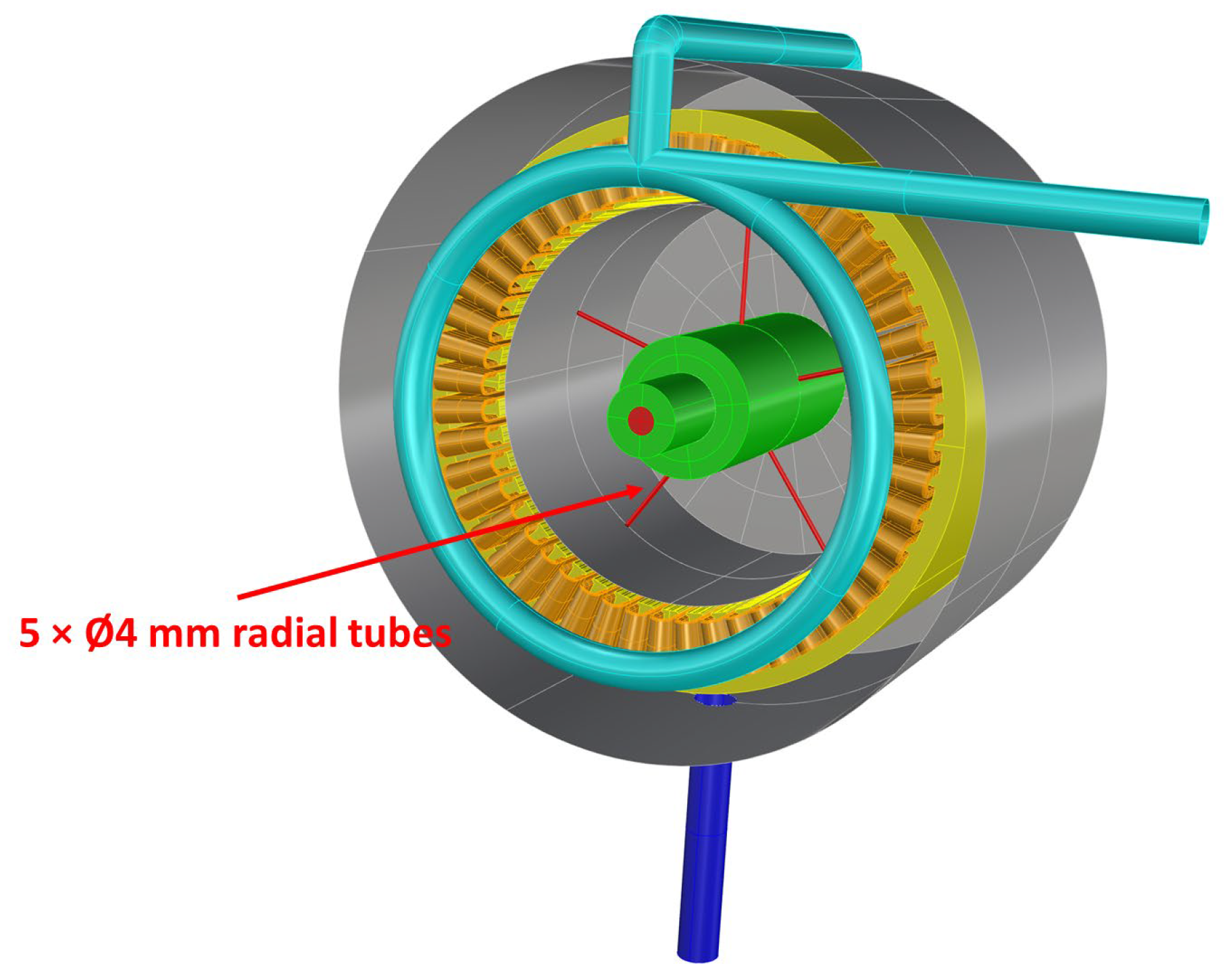
The electric motor studied in the present work, and described in detail in [11], is a 900 kW—20 krpm Permanent Magnet (PM) electric machine with 48 poles. This equipment has been developed by the University of Nottingham (UNOTT), the coordinating partner of the ORCHESTRA project. UNOTT provided the architecture as well as the thermal loads of each component of the electric motor. Using the data provided by UNOTT, CIRA designed a proper TMS based on impinging oil jets to assure that the maximum operative temperature would not exceed a maximum value of 523 K. TMS layout is composed of a delivery pump and two circular pipes of equal diameter connected by a duct placed outside the external electric motor case. Cooling oil is injected on end windings through holes located in the circular pipe, before being collected at the bottom side of the external case, thus exiting through a duct. Although the maximum temperature in the permanent magnet cavity is still limited in cases with higher flow rates, the thermal gradient induced can generate mechanical stresses and fatigue on the entire system over the operating time and problems of non-uniform thermal expansion. Thus, to better cool down this central area of the engine, a hollow shaft is used to drive additional oil in the permanent magnet cavity through five radial oil channels equally spaced by 72°, as shown in Figure 2. These radial tubes have a diameter of 4 mm and are used to inject coolant thanks to the action of the centrifugal forces generated by the rotation of the rotor.

4. Numerical Results

4.1. CFD Setup

The analysis of the TMS for the proposed configuration needs the resolution of a conjugated conductive–convective problem.
The fluid flow evolution is simulated by means of RANS (Reynolds Averaged Navier–Stokes) equations by using a coupled implicit approach and the κ-ε two-equations model as a turbulence model. The transport equations in fluid regions have the following dimensional form:
Mass equation
t ρ + · ρ v = 0
Momentum equation
t ρ v + · ρ v v = p + · τ ̿ + ρ g + S
Energy equation
t ρ h + · v ρ h = · κ f T + S h
A finite volume formulation is used to discretize Equations (1)–(3), which are solved by using the FLUENT® COUPLED algorithm associated with a well-assessed Algebraic Multigrid model. Spatial domain is discretized by means of a second-order spatial numerical upwind scheme. All the meshes used for the several evaluations were generated to use standard wall functions (near wall solution). The dimensional form of the energy transport equation in solid regions is as follows:
t ρ s h + · v ρ s h = · κ s T + S h
where
  • h: sensible enthalpy, T r e f T c p d T [kJ/kgK].
  • k: thermal conductivity [W/mK].
  • T: temperature.
  • Sh: volumetric heat source.
  • ρ: density [kg/m3].
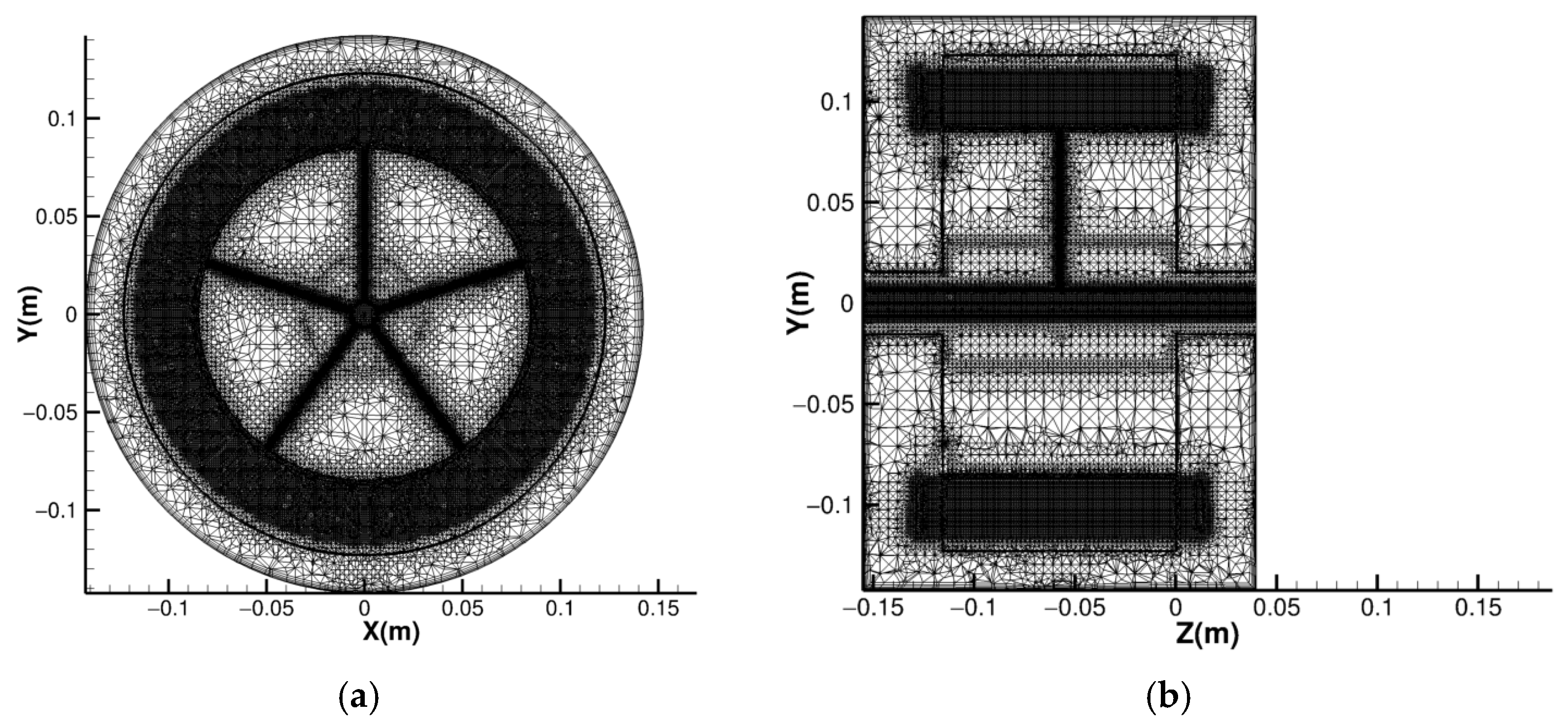
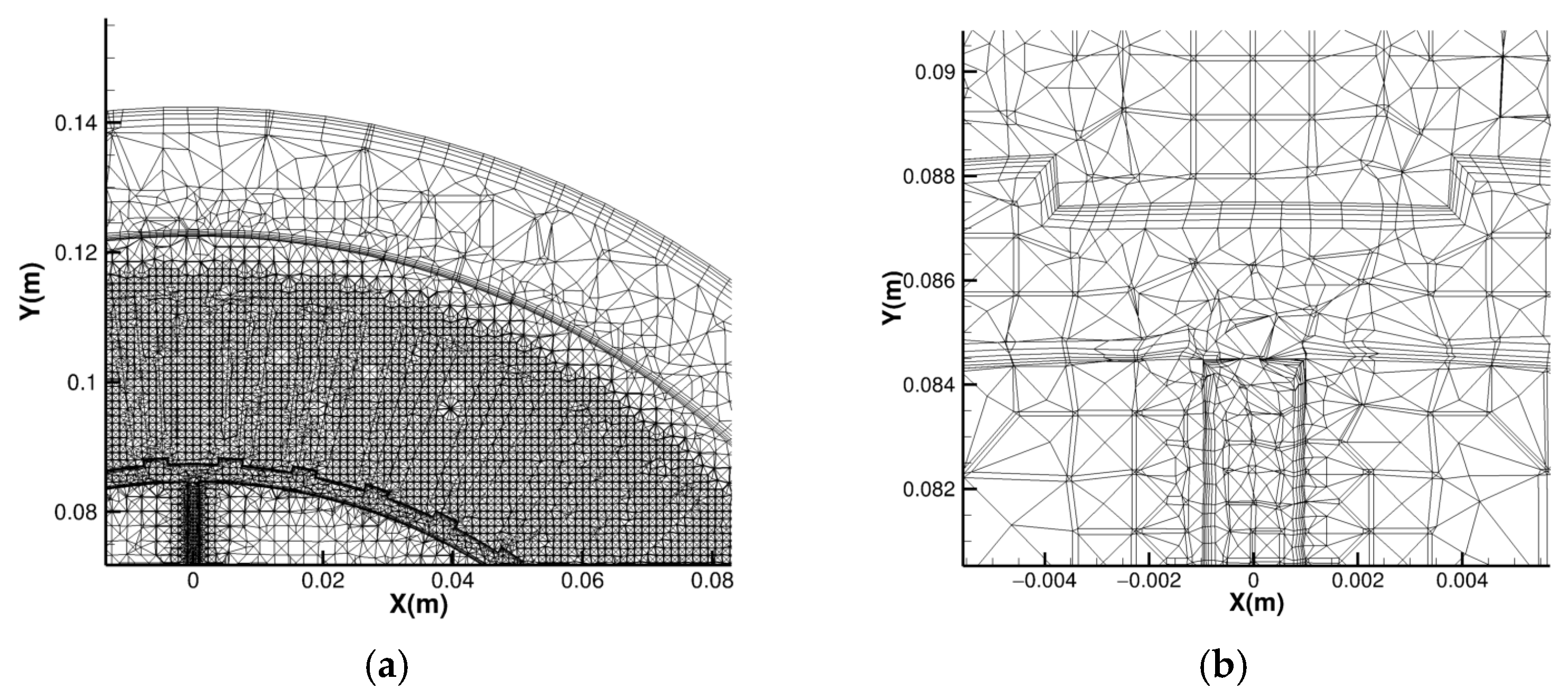
Computational mesh consists of five prismatic layers generated on each wall in the fluid domain. The mesh in the radial direction includes ten prismatic layers, while it has five layers on the rotor wall and on the stator wall, and two or three layers of tetrahedrons, used to deal with complex parts of the geometry to carry out analysis, since they effectively conform to intricate shapes while maintaining computational efficiency. Solid domains (windings and parts in ferromagnetic materials) and fluid parts where it was not possible to use prism layers are characterized by the presence of tetrahedrons, with refinements in the zones where a greater temperature gradient was expected. Figure 3a,b show the views of the mesh at constant vertical (z) and longitudinal (x) axes. It is possible to notice the refinement near the air gap, end windings and radial tubes. Figure 4 and Figure 5 show zooming of the mesh around the stator, teeth, windings and radial tubes.
Table 1 shows the boundary conditions (BCs) used for the simulations performed on grids with 35 mln cells. In particular, three mesh levels were considered: 17 million cells for the coarse mesh, 35 million cells for the medium mesh and 70 million cells for the fine mesh. The results obtained showed that the maximum difference among the results obtained using the three mesh levels was about 2%, similarly to what was found in [11]. Thus, the medium mesh was used for the numerical simulations, since it represents a proper compromise between results accuracy and numerical effort.

4.2. Planned Simulations

The simulations planned for this investigation were performed in continuity with the previous investigation concerning the originally conceived TMS, which, as already mentioned, was based on oil jets impinging the motor end windings [11]; the latter configuration is here called the baseline and is referred for comparison. Among all the simulations performed on the baseline configuration, three of them are considered to evaluate the performance of the radial tube configuration; parameters that differentiate the simulations are presented in Table 2. The label identifying a simulation includes the suffix ‘-TR’ when referring to the radial tube configuration (for example, the labels Run 4 and Run 4-TR are used to distinguish the simulations on the baseline configuration from the radial tube one). The main simulation results on the radial tube configuration for the cases described in Table 2 are reported in Table 3 where they are compared with those relating to the baseline configuration.

4.3. Results and Future Works

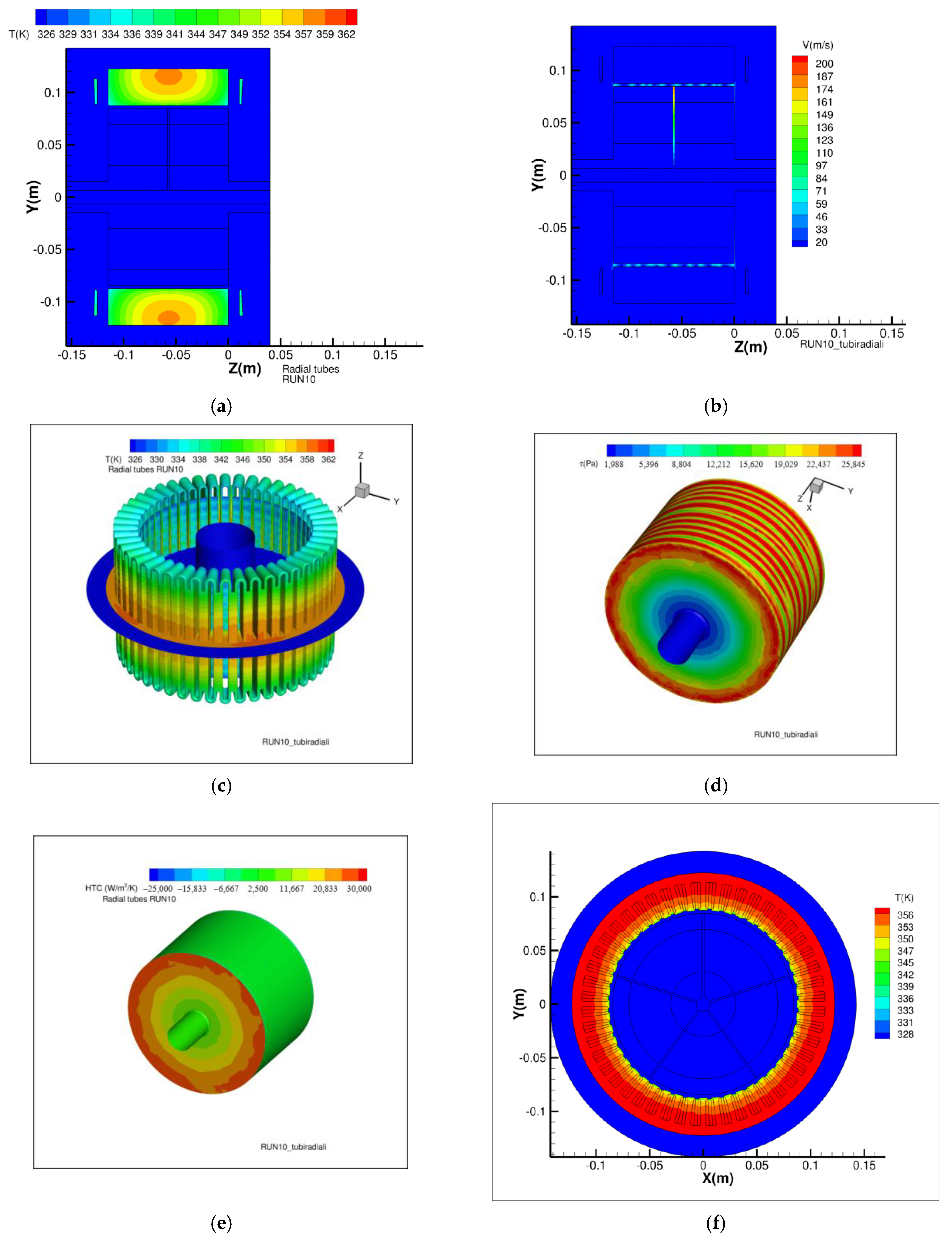
Figure 6, Figure 7 and Figure 8 show some contour maps for the discussion of results. In particular, each figure displays a number of illustrations concerning (a) the temperature and streamlines in a longitudinal plane (constant x), (b) speed magnitude in the same plane, (c) temperature on windings, (d) the Wall Shear Stress (WSS) acting on the rotor; (e) the rotor Heat Transfer Coefficient (HTC); (f) the temperature in the motor mid-section (constant z), (g) stator HTC and (h) zoomed speed magnitude at the section at constant x.
In more detail, focusing on the z-section in Figure 6, the temperature contours indicate low values in the rotor. This is attributed to the high velocities occurring in the air gap, which result from the centrifugal forces acting on the oil flowing through the radial tubes. However, higher temperatures are still observed in the middle of the stator, while the end windings receive cooling from the main oil jets.
The average and maximum values of skin friction are lower due to the centrifugal movement of the oil, which enhances the flow. Heat exchange is more significant in the rotor and the teeth, where the cooling effect of the oil coming from the shaft is particularly strong. Additionally, Taylor vortices are absent because the Reynolds number (Re) in the air gap is out of the typical range.
Figure 7 illustrates effects similar to those observed in Figure 6, but here the resin reduces even more the temperatures. In contrast, Figure 8 demonstrates how a higher flow rate of oil leads to even lower temperatures and enhanced heat exchange on the rotor and tooth surfaces. However, it is important to note that Taylor vortices emerge in the air gap, resulting in skin friction losses that are slightly greater than those in the baseline case.
Convective heat exchange coefficient along the curvilinear abscissa of a winding turn is shown in Figure 9 and Figure 10 where results from RUN4 baseline/RUN4-TR and RUN10 baseline/RUN10-TR are compared.
Figure 9 shows that the HTC values are higher for the radial tube configuration, reaching a local average increase of even 100%. This depends on a more uniform temperature distribution, an increase in convective motions in the motor housing and the fact that the overall oil flow rate is doubled, since there is an additional flow injection working in cooperation with the one exiting from the 96 circular holes. Another difference highlighted by the results shown is the asymmetry of the heat flow and the HTC on the two right and left end-windings. This is due to the fact that the motion field is not symmetrical when the rotor is rotating. Therefore, higher convective flows will be experienced on one side compared to the other, following a relative speed between the rotor and the exhaust from the outlet hole. The same asymmetry is noted between the lower and upper graphs with respect to the exit hole. The final effect is respected and the symmetries as before are not verified.
Figure 10 shows that the trends are confirmed also for the test case with larger inlet diameter and higher oil injection velocity.
The numerical studies proposed in this work are aimed at the exploration of innovative solutions to cool electric motors, and represent the first step of the design process for TMSs, which, to be considered viable, need to be verified and confirmed through experimental tests. These tests will be performed at CIRA by means of a dedicated test bench, which is currently under development within the CIRA GREENING research program. During the tests, the effect of the introduction of pipes and hollow shafts on system weight/space allocation will also be addressed, following the structural analyses that will be carried out before tests and will provide preliminary assessment of such topics.

5. Conclusions and Remarks

The commitment of aeronautic industries in contributing to the green-house carbon footprint reduction has pushed both academia and companies to investigate breakthrough technologies to meet stringent and demanding goals set by international community. Among the several breakthrough technologies proposed, a promising one is based on electrification of aircraft propulsion.
The aeronautic community has to face some challenges to accommodate the introduction and the large-scale use of such technologies. Among the main challenges to address, this paper focuses on the design of a proper TMS suitable for the thermal management of a megawatt class electric motor for future electric regional aircraft. Temperature rise, in fact, is an important factor limiting the performance of electric motors.
The present paper presents an innovative hollow shaft oil injection cooling structure for a 1 MW motor/generator developed by the University of Nottingham within the EU co-funded research project ORCHESTRA. The proposed TMS is a variant of the baseline TMS based on the impinging jet designed by CIRA for the proposed motor/generator.
In this paper, the influence of the novel hollow shaft oil injection cooling structure on the average winding temperature and the difference in injection rate at both ends of the motor has been analyzed. Considering various operating conditions, the optimization scheme of the cooling structure is determined for three cases defined in Table 2 (Run 4, Run 5, and Run 10).
As can be seen in Figure 2, there are five radial tubes connected to the hollow shaft and these are equally spaced by 72°. These holes have a diameter of 4 mm, and by centrifugal force, they inject oil in the middle of the electric motor in the airgap just below the stator. This zone, in the baseline configuration, for a TMS based on impinging jets acting on motor end windings, is not sufficiently cooled. Although in cases with a higher flow rate, the maximum temperature in this central area is still limited, a thermal gradient is generated here that can generate mechanical stresses and fatigue on the entire system over the operating time and problems of non-uniform thermal expansion.
Three different test cases have been analyzed, modifying both impinging jet diameter and cooling injection speed.
The results obtained by applying high-fidelity CFD analysis for the configuration with radial tubes have been compared with the one of the baseline TMS configuration.
The results show that the radial tube configuration guarantees higher values of HTC, due to the more uniform temperature distribution, the increased convective motions in the motor housing and the doubling of the overall oil flow rate.
A similar trend can be seen by evaluating the WSS on the tooth wall: the increase in turbulent motions stabilizes the flow and smooths out the peaks due to the Taylor vortices typical of configurations without radial tubes. On average, WSS with radial tubes is lower by about 25% with respect to the baseline configuration, generating a reduction in mechanical losses.
The radial tube configuration allows us to reduce the peak temperature in the airgap of about 40 K compared to the baseline design.

Author Contributions

Conceptualization, G.D.L., D.G.R. and A.C.; data curation, G.D.L.; formal analysis, G.D.L., D.G.R., A.P. and A.C.; investigation, G.D.L. and A.C.; methodology, G.D.L. and A.C.; project administration, A.P.; software, A.C.; supervision, A.P.; validation, G.D.L., A.C. and D.G.R.; writing—original draft, G.D.L., D.G.R., A.C. and A.P.; writing—review and editing, G.D.L., D.G.R. and A.P. All authors have read and agreed to the published version of the manuscript.

Funding

This research was funded by CIRA grant number 21-COM-0059 under the framework of PRO.R.A., the national (Italian) aerospace research programme, of which the ELECTROPLANE project is part.

Data Availability Statement

The authors declare that the data may be made available upon request by the interested party.

Acknowledgments

The authors thank all the ELECTROPLANE team members whose participants have provided (and continue to provide) valuable and constructive suggestions for the development of this research work.

Conflicts of Interest

The authors declare no conflicts of interest.

References

  1. United Nations Climate Action. Available online: https://www.un.org/en/climatechange/paris-agreement (accessed on 23 April 2025).
  2. European Council—Council of the European Union. Paris Agreement on Climate Change. Available online: https://www.consilium.europa.eu/en/policies/paris-agreement-climate/ (accessed on 23 April 2025).
  3. United Nations Climate Change. Available online: https://unfccc.int/sites/default/files/english_paris_agreement.pdf (accessed on 23 April 2025).
  4. ICAO Long Term Global Aspirational Goal (LTAG) for International Aviation. Available online: https://www.icao.int/environmental-protection/Pages/LTAG.aspx (accessed on 23 April 2025).
  5. IAG Flightpath Net Zero. Available online: https://www.iairgroup.com/media/jnmlfzxr/flightpath-net-zero-en-v3.pdf (accessed on 23 April 2025).
  6. IATA Net Zero Roadmaps. Available online: https://www.iata.org/en/programs/sustainability/roadmaps/ (accessed on 23 April 2025).
  7. Karpenko, M.; Stosiak, M.; Deptuła, A.; Urbanowicz, K.; Nugaras, J.; Królczyk, G.; Żak, K. Performance evaluation of extruded polystyrene foam for aerospace engineering applications using frequency analyses. Int. J. Adv. Manuf. Technol. 2023, 126, 5515–5526. [Google Scholar] [CrossRef]
  8. McKinsey&Company. Decarbonizing Aviation: Executing on Net-Zero Goals. Available online: https://www.mckinsey.com/industries/aerospace-and-defense/our-insights/decarbonizing-aviation-executing-on-net-zero-goals (accessed on 23 April 2025).
  9. ASUENE Blog: ICAO’s Path to Aviation Decarbonization: Strategy, Mechanisms, and Outlook. Available online: https://asuene.com/us/blog/icaos-path-to-aviation-decarbonization-strategy-mechanisms-and-outlook (accessed on 23 April 2025).
  10. EASA Pro. European Aviation Environmental Report 2025: Turning Goals into Action is Critical for Future of Aviation. Available online: https://www.easa.europa.eu/en/newsroom-and-events/press-releases/european-aviation-environmental-report-2025-turning-goals-action (accessed on 23 April 2025).
  11. CORDIS—European Commission. ORCHESTRA Project. Available online: https://cordis.europa.eu/project/id/101006771 (accessed on 23 April 2025).
  12. Di Lorenzo, G.; Romano, D.G.; Carozza, A.; Pagano, A. Cooling of 1 MW Electric Motors through Submerged Oil Impinging Jets for Aeronautical Applications. Aerospace 2024, 11, 585. [Google Scholar] [CrossRef]
  13. Ministero Dell’università e Della Ricerca. Available online: http://www.ricercainternazionale.mur.gov.it/spaziale/prora.aspx (accessed on 23 April 2025).
  14. Di Lorenzo, G.; Romano, D.G.; Carozza, A.; Pagano, A. Nanofluids as Coolants to Improve the Thermal Management System of a High-Power Aircraft Electric Motor. Electronics 2025, 14, 911. [Google Scholar] [CrossRef]
  15. Smithsonian National Air and Space Museum. 1903 Wright Flyer. Available online: https://airandspace.si.edu/collection-objects/1903-wright-flyer/nasm_A19610048000#:~:text=On%20December%2017%2C%201903%2C%20the,at%20Kitty%20Hawk%2C%20North%20Carolina (accessed on 23 April 2025).
  16. Anderson, J.D. The Airplane: A History of Its Technology; American Institute of Aeronautics and Astronautics: Reston, VA, USA, 2002. [Google Scholar]
  17. Wikipedia: Aeolipile. Available online: https://en.wikipedia.org/wiki/Aeolipile (accessed on 23 April 2025).
  18. Espacenet: Whittle Patent. Available online: https://worldwide.espacenet.com/patent/search/family/009723409/publication/GB347206A?q=GB347206A (accessed on 23 April 2025).
  19. Sir Frank Whittle. The First Patent. Available online: https://frankwhittle.co.uk/the-first-patent/ (accessed on 23 April 2025).
  20. ThoughtCo. The History of the Jet Engine. Available online: https://www.thoughtco.com/history-of-the-jet-engine-4067905 (accessed on 23 April 2025).
  21. Google Patents. Available online: https://patents.google.com/patent/US2404334A/en (accessed on 23 April 2025).
  22. Gunston, B. The Development of Jet and Turbine Aero Engines; Haynes Publishing: Yeovil, UK, 2006. [Google Scholar]
  23. Mattingly, J.D.; Heiser, W.H.; Boyer, K.M.; Haven, B.A.; Pratt, D.T. Aircraft Engine Design, 3rd ed.; American Institute of Aeronautics and Astronautics, Inc.: Reston, VA, USA, 2018. [Google Scholar]
  24. Sayyaadi, H.; Mehrabipour, R. Efficiency enhancement of a gas turbine cycle using an optimized tubular recuperative heat exchanger. Energy 2012, 38, 362–375. [Google Scholar] [CrossRef]
  25. Siddique, M.; Khaled, A.-R.A.; Abdulhafiz, N.I.; Boukhary, A.Y. Recent Advances in Heat Transfer Enhancements: A Review Report. Int. J. Chem. Eng. 2010, 2010, 28. [Google Scholar] [CrossRef]
  26. Chapman, J.W.; Hasseeb, H.; Schnulo, S. Thermal Management System Design for Electrified Aircraft Propulsion Concepts; NASA/TM-20205011477, March 2021; NASA—Glenn Research Center: Cleveland, OH, USA, 2021. [Google Scholar]
  27. Alsouda, F.; Bennett, N.S.; Saha, S.C.; Salehi, F.; Islam, M.S. Vapor Compression Cycle: A State-of-the-Art Review on Cycle Improvements, Water and Other Natural Refrigerants. Clean Technol. 2023, 5, 584–608. [Google Scholar] [CrossRef]
  28. Swain, B.; Memon, S.A.; Achari, A.M.; Mehta, V. A review on analysis and modelling of impinging jets. J. Mech. Eng. Res. Dev. (JMERD) 2019, 42, 43–51. [Google Scholar] [CrossRef]
  29. THERMOPEDIA. Available online: https://www.thermopedia.com/content/872/ (accessed on 10 July 2024).
  30. Chen, Q.; Zhang, X.; Zhang, J. Effects of Reynolds and Prandtl Numbers on Heat Transfer Around a Circular Cylinder by the Simplified Thermal Lattice Boltzmann Model. Commun. Comput. Phys. 2015, 17, 937–959. [Google Scholar] [CrossRef]
  31. Rey, C.; Rosant, J.-M. Reynolds Number and Prandtl Number Influence on the Determination of Isotropic Velocity and Temperature Turbulent Length Scales. In Advances in Turbulence; Comte-Bellot, G., Mathieu, J., Eds.; Springer: Berlin/Heidelberg, Germany, 1987; pp. 209–214. [Google Scholar]
  32. Shukla, A.K.; Dewan, A. Flow and thermal characteristics of jet impingement: Comprehensive review. Int. J. Heat Technol. 2017, 35, 153–166. [Google Scholar] [CrossRef]
  33. Darwish, A.M.; El-Kersh, A.-F.; El-Sheikh, M.N.; El-Moghazy, I.M. A Review on Nanofluid Impingement Jet Heat Transfer. Int. J. Nanotechnol. Allied Sci. 2017, 1, 1–15. [Google Scholar]
  34. Fitzgerald, J.A.; Garimella, S.V. A study of the flow field or a confined and submerged impinging jet. Int. J. Heat Mass Transfer. 1998, 41, 1025–1034. [Google Scholar] [CrossRef]
  35. Lupton, T.L.; Murray, D.B.; Robinson, A.J. The Effect of Varying Confinement Levels on the Heat Transfer to a Miniature Impinging Air Jet; Eurotherm: Eindhoven, The Netherlands, 2008. [Google Scholar]
  36. Hogan, B.E. Convective Heat Transfer in Rotating, Circular Channels. Bachelor of Science in Engineering as Recommended by the Department of Mechanical Engineering; Massachusetts Institute of Technology: Cambridge, MA, USA, 2002. [Google Scholar]
  37. Abdulrahman, G.A.Q.; Alharbi, S.M. Laminar and turbulence forced heat transfer convection correlations inside tubes. A review. arXiv 2024, arXiv:2401.02998v1. [Google Scholar] [CrossRef]
  38. Zhang, Z.-C.; Song, Q.; Bilal, A. Innovative Design of the Cooling Topologies for Electric Vehicle Motors. IOP Conf. Ser. Mater. Sci. Eng. 2019, 533, 012021. [Google Scholar]
Figure 1. (a) Jet engine, (b) turbojet engine and (c) turboprop engine.
Energies 18 03390 g001
Figure 2. TMS oil cooling design (green: hollow shaft; red radial tubes and oil jet; yellow: stator; orange: end windings; cyan: oil inlet piping; blue: oil outlet; grey: case).
Energies 18 03390 g002
Figure 3. Details of the mesh, in the case with the presence of resin between the windings and d = 2 mm; (a) section at z = cost; (b) section at x = cost.
Energies 18 03390 g003
Figure 4. Mesh details: (a) stator; (b) windings along z-axis.
Energies 18 03390 g004
Figure 5. Mesh details: (a) teeth and airgap; (b) radial tube.
Energies 18 03390 g005
Figure 6. Contour maps for Run 4-TR: (a) temperature and streamlines at x = const.; (b) velocity magnitude; (c) temperature on windings; (d) WSS on the rotor; (e) HTC on rotor; (f) temperature at section at z = const.; (g) HTC on the complete stator; (h) zoomed velocity magnitude at section at x = const.
Energies 18 03390 g006aEnergies 18 03390 g006b
Figure 7. Contour maps for Run 5-TR: (a) temperature and streamlines at x = const.; (b) velocity magnitude; (c) temperature on windings; (d) WSS on the rotor; (e) HTC on rotor; (f) temperature at section at z = const.; (g) HTC on the complete stator; (h) zoomed velocity magnitude at section at x = const.
Energies 18 03390 g007aEnergies 18 03390 g007b
Figure 8. Contour maps for Run 10-TR: (a) temperature and streamlines x = const.; (b) velocity magnitude; (c) temperature on windings; (d) WSS on the rotor; (e) HTC on rotor; (f) temperature at section at z = const.; (g) HTC on the complete stator; (h) zoomed velocity magnitude at section at x = const.
Energies 18 03390 g008aEnergies 18 03390 g008b
Figure 9. HTC for upper (a) and lower (b) winding. Comparison between baseline (red) and radial tube configuration (green) from test cases RUN4 baseline and RUN4-TR, respectively.
Energies 18 03390 g009
Figure 10. HTC for (a) upper (#1) and (b) lower (#25) winding. Comparison between baseline (red) and radial tube configuration (green) from test cases RUN10 baseline and RUN10-TR, respectively.
Energies 18 03390 g010
Table 1. Boundary condition considered for CFD analyses.
Boundary ConditionsZones
Mass flow inletInlet holes
OutflowExit hole
Moving wallExternal rotor surfaces
Wall/no slipThe remainder
Constant heat fluxTeeth
Uniform heat power source (W/m3)Stator yoke, end-winding, copper
Table 2. Meaningful parameters of simulations performed to compare TMSs with/without radial tubes.
Id. Case Inlet Diameter [mm]Oil Injection Speed [m/s]
Run 420.5
Run 521
Run 1041
Table 3. CFD results for the three evaluations.
Run/OutputRUN4RUN4-TRRUN5RUN5-TRRUN10 RUN10-TR
Vout [m/s]−0.568−0.95−1.15−1.05−4.49−3.70
Vout_theor [m/s]−0.57−1.00−1.15−1.15−4.52−4.00
Tout, ave [K]372328325327331325
WSS, ave [Pa]14,14310,02317,29310,03917,58515,983
WSS, max [Pa]33,51730,19635,71834,44239,41641,500
Tmax (stator) [K]402.3363.6379.8363.0360.8358.5
Tave (stator) [K]395.0356.0372.5355.4354.1350.8
Tmax (EW) [K]402.3363.6379.8363.0360.8358.2
Tave (EW) [K]392.7353.3370.2352.7351.8347.7
Tmax (Tooth) [K]402.3357.8379.8357.5360.8351.8
Tave (Tooth) [K]385.6343.6362.9343.1344.6337.3
Tmax (Rotor) [K]377.3332.8353.8332.9336.7325.5
Tave (Rotor) [K]375.8330.2352.3329.6334.7325.2
Tmax [K]402.3363.6379.8363.0360.8358.5
ΔTMax (%)-1.55-1.39-0.13
Disclaimer/Publisher’s Note: The statements, opinions and data contained in all publications are solely those of the individual author(s) and contributor(s) and not of MDPI and/or the editor(s). MDPI and/or the editor(s) disclaim responsibility for any injury to people or property resulting from any ideas, methods, instructions or products referred to in the content.