Abstract
A significant portion of energy losses in industrial systems arises from the inefficient use of high-temperature exhaust gases, emphasizing the need for enhanced heat recovery strategies. This study aims to improve energy efficiency by examining the effects of radiation-intensifying inserts on combined radiative and convective heat transfer in flue-gas heated channels. A systematic literature review revealed a research gap in understanding the interaction between these mechanisms in flue-gas heat exchangers. To address this, analytical calculations were conducted for two geometries: a radiation-intensifying plate between parallel plates and the same insert in a circular pipe. The analysis covered a range of gas-flue and wall temperatures (560–1460 K and 303–393 K, respectively), flow velocities, and spectral emissivity values. Key performance metrics included Reynolds and Nusselt numbers to assess flow resistance and heat transfer. Results indicated that flue-gas temperature has the most significant effect on total rate of heat transfer, and the insert significantly enhanced radiative heat transfer by over 60%, increasing flow resistance. A local Nusselt number minimum at a length-to-diameter ratio of approximately 26 suggested transitional flow behavior. These results provide valuable insights for the design of high-temperature heat exchangers, with future work planned to validate the findings experimentally.
1. Introduction
In recent years, the rising global population, combined with efforts to improve living standards, has led to an unprecedented increase in energy demand [1]. Significant amounts of energy from energy-intensive industries are lost through flue-gas emissions. According to the U.S. Department of Energy (US DOE), industries lose nearly half (~50%) of their input energy via exhaust gases and cooling water [2]. Perhaps the most significant topic discussed in recent decades is the limited amount of fossil fuels, which, at current consumption rates, may be depleted within the next century, depending on the type of fuel [3,4]. In the context of modern economic development, it is critical to find ways to combine growth with environmental goals. Thus, sustainable economic growth can only be achieved by enhancing energy efficiency through technologies that improve heat transfer and consequently reduce industrial heat production emissions [5].
Active and passive heat transfer improvement techniques are commonly applied to enhance energy efficiency. Active heat transfer enhancement methods involve supplying external energy to boost the thermal efficiency of latent heat thermal energy storage (LHTES) systems. Such methods encompass mechanical devices, vibrations, jet impingement, injection, and other externally powered interventions [6]. On the other hand, passive methods enhance thermal efficiency without needing extra power, making them economical and dependable in energy conversion systems [7,8]. These techniques effectively improve thermal performance in systems without increasing energy usage or requiring additional energy [9].
Passive heat transfer enhancement methods involve the application of inserts like twisted tapes, conical strips, baffles, and winglets, as well as porous materials, coil/helical/spiral tubes, roughened surfaces (corrugated or ribbed), extended surfaces (fins), and nanofluids [7,10]. Twisted tape inserts are particularly effective at improving heat transfer performance without negatively affecting the overall system efficiency [11]. Passive techniques create swirl flows, decrease thermal resistance, and extend fluid residence times, significantly benefiting both laminar and turbulent flow conditions [12]. However, it should be noted that using inserts leads to increased pressure drop, so it is essential to evaluate the overall enhancement of thermal performance carefully. Both active and passive heat transfer enhancement methods are critically important in industrial sectors, including thermal power plants, to achieve higher energy savings and enhance the economic efficiency of thermal systems [13].
Many researchers analyze the heat transfer and fluid dynamics in various engineering systems, often using numerical modeling (CFD) and analyzing different ways to enhance heat transfer in pipes and channels [14,15,16]. The field most studied when improving heat transfer efficiency using passive techniques is convective heat transfer, as most deal with the heat exchange between a moving fluid and a solid surface. Convection is the main heat transfer mechanism in such situations. Significantly few authors have addressed radiative heat transfer [14,17,18].
A systematic literature review was used to determine whether increasing heat transfer efficiency using radiation-enhancing inserts has been sufficiently studied. A systematic literature review (SLR) is a rigorous and methodologically structured approach used to identify, select, and critically evaluate existing studies to address a clearly defined research question [19]. This process is guided by a predefined protocol, including explicit inclusion and exclusion criteria established before the review. An SLR involves a comprehensive and transparent search across multiple academic databases, thereby ensuring reproducibility and enabling verification by other researchers. The method requires a well-defined search strategy tailored to the specific research objective, and the retrieved data are systematically organized and analyzed within a specified timeframe. To ensure methodological transparency, the review must provide detailed documentation of the search terms, strategies, database sources, platforms used, search dates, and any limitations applied during the process. The research question was chosen using the PICO method, a structured approach that aids in formulating research questions [20]. This method is popular in many fields, from medicine to social sciences and thermodynamics. PICO stands for population, problem, source of information (P), intervention, factors (I), comparison, circumstances, situation (C), and outcome, the main point of interest (O). Researchers widely utilize this framework to develop precise research questions and streamline literature reviews. In this study, the research question formulated using the PICO strategy was, “How does the heat transfer change due to radiation when a radiation-intensifying turbulator is placed in the fire-tube at high temperature?”
Once the research question was formulated, the next step involved identifying relevant scientific articles. The term “eligibility” is defined as the fact of having the necessary qualities or satisfying the required conditions [21]. Selecting appropriate articles requires determining the most relevant keywords. These keywords were established based on predefined inclusion criteria, which in this context included the application of turbulators, heat transfer methods, heat transfer intensifier, article type, the purpose of the applied technology, the fluid used in the system, and the search area. Inclusion criteria define an article’s essential elements to qualify it for inclusion in a systematic literature review. The number of articles was reduced by using inclusion and exclusion criteria.
Appropriate articles were examined again carefully to ensure a deeper analysis. As a result, it was decided to read the selected scientific publications more comprehensively, which allowed to identify several key ideas. These articles focus on different aspects of heat transfer enhancement and system performance, each addressing specific issues and challenges relevant to the field.
The sources collectively explore methods and analyses to improve heat transfer in various engineering applications, particularly within heat exchangers and thermoelectric generator (TEG) systems. The research employs both experimental [17,22,23,24,25,26,27,28] and numerical approaches, notably computational fluid dynamics (CFD) [14,17,23,24,26,27,29,30,31]. A detailed review of the selected articles reveals several recurring thematic areas, each addressing specific aspects of heat transfer enhancement, system applications, and performance evaluation methodologies.
A primary focus across the sources is enhancing heat transfer through various passive strategies. Turbulators, or inserts, are widely recognized for their ability to create turbulent motion and improve heat exchange [31,32]. Examples of inserts studied include twisted tapes [23,31,32,33,34,35,36,37,38,39]. Twisted tapes combined with rings or other modifications like perforations [37,39], wire coils [28,29,40], ribs [30], vortex generators [41], winglets (such as delta winglets) [26,42,43], obstacles [32], pin fins [32,44,45], dimples (spherical, cylindrical) [46], and semi-circular inserts [30]. These inserts disrupt the flow and induce vortices, increasing mixing and heat transfer, often at the expense of increased pressure drop [47].
Furthermore, porous media are investigated as a means to enhance heat transfer, potentially acting as a convection–radiation converter in laminar flow [48]. The characteristics of pulsating flows (frequency, amplitude, turbulence intensity) in pipes are also noted as influencing gas-dynamic and heat-exchange perfection [49].
The research covers diverse heat exchange systems and their applications. Fire-tube boilers/generators are analyzed through experimental studies and modeling [17,24,27], particularly focusing on heat transfer (convective and radiative) and pressure loss in the fire-tube [17]. Thermoelectric generator (TEG) systems are investigated for waste heat recovery by converting temperature differences into electrical energy [22], with studies focusing on configurations involving multiple TE modules placed between hot and cold ducts, examined under varying inlet air temperatures, mass flow rates, module connection types, and the presence or absence of turbulating inserts. These systems could also be widely used in waste heat recovery, power plants, chemical reactors, cooling electronic components, and turbine blades.
Numerical modeling, predominantly using computational fluid dynamics (CFD), is a crucial tool for analyzing flow and heat transfer phenomena [17,26,30]. The Reynolds-averaged Navier–Stokes (RANS) equations are commonly employed for turbulent flow simulations [41,50,51]. A critical aspect of CFD is the meshing process, which must be suitable for accurately calculating essential variables in the governing equations. Mesh independence analysis is performed to determine an appropriate mesh structure that balances accuracy and computational efficiency [52]. The quality of the mesh is assessed using criteria like skewness and aspect ratio [52]. CFD models are often validated by comparing their predictions with experimental data [17,27] or established empirical correlations [23,30]. Software like ANSYS Fluent 2025 R1 is used for simulations in [29].
Experimental investigations are conducted to gather data on the performance of heat exchange systems and enhancement techniques [17,22,24,25,26,28,35]. These experiments involve measuring key parameters such as temperature (inlet, outlet, wall, flue-gas, water) [53], mass flow rate [15] pressure drop, current, and voltage. Specialized experimental setups, such as those for testing TEG systems or fire-tube heat generators, are constructed. The experimental setup is validated by comparing results for baseline configurations (e.g., smooth pipes).
Evaluating the effectiveness of enhancement methods involves calculating parameters like the Nusselt number (Nu) for heat transfer [15,26,30,35,37,39,53]. While these inserts effectively increase heat transfer, this typically comes at the cost of a higher pressure drop due to increased flow resistance [16,37,40,46,54,55,56]. Various performance indicators are used, such as the thermal enhancement factor (TEF), which considers the trade-off between heat transfer enhancement and pressure drop increase [53]. Optimization processes are employed to find the best parameters for heat exchanger designs, often utilizing techniques like Genetic Algorithms (GA) [17,27,29,57]. Also, Artificial Neural Networks (ANN) can be used to model performance characteristics to support optimization [37,57,58]. Different objective functions are considered in optimization, aiming to maximize heat exchange, minimize pressure losses, or optimize parameters based on thermal efficiency, exergy efficiency, or economic considerations.
After conducting a systematic literature review and noting that there are too little articles examining in detail the sum of convective and radiative heat transfer mechanisms in the flue-gas/water exchanger‘s tubes of boilers, it was decided to create a calculation methodology to determine the influence of radiation. This study investigates how radiation enhances heat transfer in two different scenarios. The first scenario calculates the sum of convective and radiative heat transfer when a radiation-intensifying plate (shield) is placed between two infinite plates, and the flue-gas passes through it. The second scenario calculates the sum of convective and radiative heat transfer when the radiation-intensifying plate is inserted into the tube of the fire-tube boiler. Both models were simulated, and calculations were made, using the MATLAB 2025 R1 programming language. Analytical analysis and visualizations helped to comprehend the overall influence of using the inserted plate.
Although passive heat transfer enhancement methods have been widely studied, the combined effect of convection and radiation, particularly in flue-gas boiler tubes with radiation-intensifying inserts, remains insufficiently explored. Most research focuses on convective mechanisms, while radiation, which can significantly influence heat transfer at high temperatures, is often overlooked. To address this gap, the present study develops an analytical methodology using MATLAB to evaluate the combined heat transfer performance in two configurations: between two infinite plates and within a flue-gas boiler tube. The outcomes provide valuable insights into the role of radiation in overall heat transfer, offering a foundation for more accurate thermal performance predictions and improved system design. The following sections describe the mathematical modeling, simulation process, and analysis of results.
2. Analytical Model
An analytical model was developed and applied to two configurations to evaluate the effect of radiative heat transfer on overall thermal performance. Initially, a simplified geometry—an insert placed between two infinite parallel plates—was used to assess the fundamental impact of radiation enhancement. In the second stage, the model was extended to a more practical configuration by placing the radiation-intensifying insert inside a pipe to apply the results to shell boiler systems, where hot flue-gas typically flows through internal tubes. The first model represents a simplified 2D configuration between infinite parallel plates, while the second approximates a real 3D cylindrical pipe, modeled under axial symmetry assumptions. These systems often employ turbulators to enhance convective heat transfer; however, such elements significantly increase aerodynamic resistance and energy consumption for flue-gas transport. Flat plate-type inserts in high-temperature regions offer a potential solution by enhancing radiative heat transfer while minimizing pressure losses.
Flue-gas is characterized by low emissivity, meaning that heat transfer from the gas to the boiler tubes in conventional water-heating systems occurs primarily through convection. When straight plate-type inserts are placed inside the tubes carrying the flue-gases, these inserts absorb heat from the convective flow and subsequently transfer it to the water-cooled tube walls via thermal radiation. Radiation-enhancing inserts can be effectively applied in shell boilers and other similar thermal equipment to increase the overall heat transfer efficiency. By promoting radiative heat exchange, such inserts help reduce the energy required for flue-gas transport through the boiler, as their aerodynamic resistance is significantly lower than conventional turbulators, which typically increase flow turbulence through vortex generation or flow disruption.
Calculations were performed for a typical composition of combustion products, where the flue-gas mainly consists of diatomic gases that do not radiate heat, meaning their presence or changes in quantity have little effect on the radiation intensity of the flue-gas flow. The radiating part of the flue-gas comprises only gases containing triatomic atoms or more and solid particles. In our calculations, the composition of the radiating gases from natural gas combustion products is CO2 = 13%, H2O = 11%. The rest are non-radiative diatomic gases, such as nitrogen.
In both modeled cases, the surrounding medium was hot flue-gas, with temperatures ranging from 573.15 K to 1473.15 K. Simulations were conducted assuming a wall spectral emissivity of ε = 0.9, flue-gas spectral emissivity εd = 0.2, and flue-gas flow absorptivity Ad = 0.2. The radiation-intensifying plate used in this study is made of steel, commonly used in high-temperature heat exchangers due to its thermal stability and mechanical strength. For radiative heat transfer calculations, the emissivity of the plate surface was assumed to be 0.9, reflecting its high capacity to emit thermal radiation. The operating conditions used in the analytical model were chosen to represent typical thermal and flow parameters found in industrial flue-gas heat recovery systems. The temperature range of 560–1460 K for the flue gases and 303–393 K for the pipe walls corresponds to combustion products from natural gas and standard cooling water temperatures, respectively. Emissivity and absorptivity values were selected based on the radiative properties of combustion gases and commonly used metallic surfaces to ensure the model’s relevance to real-world high-temperature applications.
Throughout this paper, the term “heat transfer rate” is used to denote the overall thermal performance of the system, expressed in kilowatts (kW), including all modes of heat transfer involved. It reflects the total heat transfer rate associated with the flue-gas flow, accounting for both convective and radiative components and their combined effect on heat exchange efficiency. The values were obtained by integrating the local heat transfer over the surface area of the tube wall under different flue-gas flow conditions. The plotted heat transfer rate values represent the net thermal output as a function of flue-gas flow temperature and velocity. Presenting the results regarding heat transfer rate provides a comprehensive and quantifiable measure of heat transfer intensity across various operating regimes.
2.1. Boundary Conditions When the Radiation-Intensifying Plate Is Placed Between Two Infinite Plates
The radiation-intensifying plate is inserted between two infinite plates. To simplify the simulations, the temperature of these plates is assumed to be equal to the temperature of the fluid receiving the heat transfer. Flue-gas flows between the plates at temperatures ranging from 573.15 K to 1473.15 K. The simulations are conducted under steady-state flow conditions over a selected area of 1 m2. The spectral emissivity of the wall is set at ε = 0.9, the spectral emissivity of the flue-gas flow at εd = 0.2, and the absorption coefficient of the flue-gas flow at Ad = 0.2. The geometry of the channel with an inserted infinite radiation-intensifying plate is shown in Figure 1.
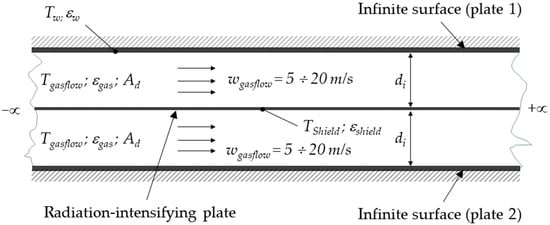
Figure 1.
Geometry of a channel with infinite plates with an inserted plate.
2.2. Governing Equations for Heat Transfer Calculations
Calculations of Reynolds number:
where w—velocity of flue-gas (m/s), di—characteristic dimension of channel (m) or the distance between the wall and the shield, υ—kinematic viscosity (m2/s) [59,60].
Calculations of Nusselt number:
When the flow is laminar, Re < 2000:
where Pr—Prandtl number.
Grashof number is defined:
where β—thermal expansion coefficient of the fluid volume (1/K), g—the acceleration due to gravity (g = 9.81 m/s2), ∆T—the temperature difference that results in natural convection (K). Index f and p show at which temperature the physical parameters of the fluid are taken in the criteria, i.e., either at the fluid or surface temperature.
When the flow is transitional, 2000 < Re < 10,000:
When the flow is turbulent, Re > 10,000:
Heat transfer coefficient by convection:
where λ—thermal conductivity coefficient (W/m·K).
Calculations of the shield wall temperature:
The temperature of the inserted infinite shield (plate) is found by balancing the heat received by the shield and the heat given to the shield. The shield receives the heat by convection from the flue-gas flow:
where Fshield—surface area of shield (m2), α—heat transfer coefficient (W/m2·K), Tgasflow—temperature of flue-gas, and Tshield—temperature of shield (K).
The shield receives the heat by radiation from flue-gas:
where εgasflow—flue-gas spectral emissivity εgasflow = 0.2, Ad—absorption of flue-gas Ad = 0.2, εshield—spectral emissivity of shield εshield = 0.9, σ0—Stefan–Boltzmann constant (σ0 = 5.67 10−8 W/m2·K4) [24]
The shield radiates the heat to the walls:
where φshield—angular coefficient of radiation from the shield φshield = 1, C0—absolutely black body radiation coefficient C0 = 5.67 W/m2·K4.
In this analytical model, the view factor between the radiation-intensifying plate and the adjacent wall is assumed to be φ = 1. This assumption is appropriate for idealized geometries where the radiating surface faces a large, unobstructed opposing surface. It simplifies the radiative exchange calculation and allows direct analytical expressions without complex numerical integration.
εt—the supposed emissivity of the surface system:
where εw emissivity of wall surface εw = 0.9.
Calculations of the shield temperature:
Balance equation for calculating the temperature of the shield:
Qcon—heat transfer rate from flue-gas flow by convection, Qrad—heat transfer rate from flue-gas flow by radiation, Qrshield—heat transfer rate from shield to wall by radiation.
Calculations of heat flows:
Heat transfer rate from the shield to the wall by radiation:
where Tw—temperature of the wall (K).
Heat transfer rate from flue-gas flow by radiation:
where εs is the emissivity of the wall, and Fw is the wall surface area, m2.
Heat transfer rate from flue-gas flow by convection:
2.3. Boundary Conditions When the Radiation-Intensifying Plate Is Placed into the Tube of the Flue-Gas Boiler
The radiation-intensifying plate is inserted into the tube of the flue-gas boiler, as shown in Figure 2. The calculations are made by varying the flue-gas flow rate, the pipe diameter, and the water temperature to which the heat is transferred. The flue-gas flow temperature is varied from 573.15 K to 1473.15 K, the flue-gas flow velocity is varied from 5 m/s to 10 m/s, the diameter of the pipe is varied from 0.05 m to 0.1 m, and the wall temperature is varied from 303.15 K to 393.15 K. The calculations assume that the wall temperature of the pipe is the same as the temperature of the water cooling the pipes, the body spectral emissivity of the inserted plate and the wall is ε = 0.9, the spectral emissivity of the flue-gas is εd = 0.2, and the flue-gas absorption coefficient Ad = 0.2.
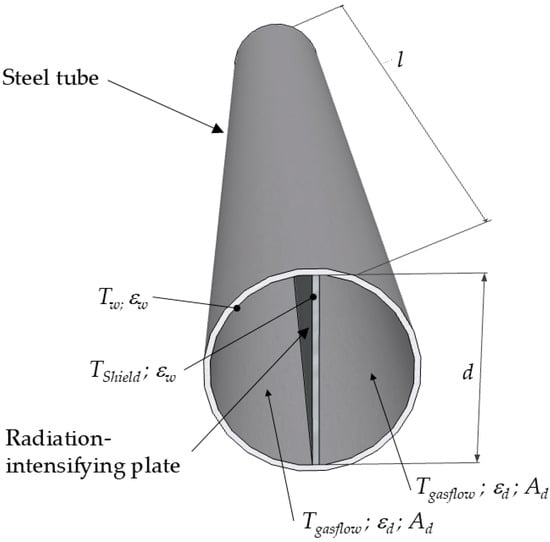
Figure 2.
Geometry of a channel with a radiation-intensifying plate into the tube of the flue-gas boiler.
2.4. Governing Equations for Heat Transfer Calculations
Calculations are made by dividing the pipe into individual sections, the length of the sections being 0.1 m; see Figure 3.
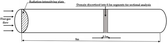
Figure 3.
Schematic of the computational domain with flue-gas flow, radiation-intensifying plate, and discretization into 0.1 m segments for sectional analysis.
Calculations of Reynolds number:
where w—velocity of flue-gas (m/s), dek—characteristic dimension of channel (m) or the distance between the wall and the shield, υ—kinematic viscosity (m2/s)
Calculations of characteristic channel dimension:
where f is the cross-sectional area of the channel (m2):
P is the perimeter of the channel (m):
where d is the diameter of the channel (m):
Calculations of Nusselt number:
When the flow is laminar, Re < 2000:
Grashof number is defined:
where β—thermal expansion coefficient of the fluid volume (1/K), g—the acceleration due to gravity (g = 9.81 m/s2), ∆T—the temperature difference that results in natural convection (K).
The multiplier evaluates the variation of the heat release coefficient in the stabilization section, and its values are given in Table 1.

Table 1.
Multiplier values for laminar flow.
When the flow is transitional, 2000 < Re < 10,000, the Nu number can be calculated by the Equation (4).
When the flow is turbulent, Re > 10,000:
The multiplier evaluates the variation of the heat release coefficient in the stabilization section, and its values are given in Table 2.
Table 2.
Multiplier values for turbulent flow.
The calculation of the plate temperature is based on Equation (11).
Calculations of the heat flows in the pipe are performed using Equations (12)–(14), which estimate the heat flow from the shield to the wall by radiation, the heat flow from the gas by radiation, and the heat flow from the gas by convection.
2.5. Limitations of the Analytical Approach
While the analytical model provides valuable insights into radiative and convective heat transfer mechanisms, several limitations should be acknowledged. The geometries were simplified using two-dimensional or axially symmetric assumptions, which may not capture complex three-dimensional flow structures or localized effects. Material properties such as emissivity and absorptivity were assumed to be constant, although in real systems they can vary with temperature and surface conditions. The use of a grey-body radiation model excludes spectral variations, which may be significant in high-temperature gas mixtures. Additionally, the absence of experimental validation means the model’s predictive accuracy remains theoretical. These simplifications are necessary for analytical tractability but should be considered when interpreting the results and applying them to real-world systems.
3. Results
3.1. The Case of the Radiation-Intensifying Plate Is Positioned Between Two Infinite Plates
The graph presented in Figure 4 illustrates the variation of heat transfer rate (W) as a function of flue-gas flow temperature (K) for different flue-gas flow rates (w = 5, 10, 15, and 20). The x-axis represents the flue-gas flow temperature in K, ranging from approximately 550 K to 1500 K, while the y-axis represents the heat transfer rate in watts (W), spanning from approximately 5 kW to 155 kW. The data show a positive correlation between flue-gas flow temperature and heat transfer rate, indicating that as the flue-gas flow temperature increases, the heat transfer rate also increases for all tested flue-gas flow rates. The plotted curves demonstrate that higher flue-gas flow rates (W) produce greater heat transfer rate values at any given temperature. Notably, the difference in heat transfer rate between different flue-gas flow rates becomes more pronounced at higher temperatures. The correlation suggests that convective heat transfer is significantly influenced by both flue-gas flow temperature and flue-gas flow rate, with increasing flue-gas flow rates amplifying the heat transfer rate. This behavior aligns with expectations based on convective heat transfer principles, where an increase in mass flow rate enhances the convective heat transfer coefficient, thereby augmenting the overall heat transfer rate.
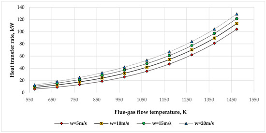
Figure 4.
Total heat transfer rate comparison at different flue-gas flow rates.
Figure 5 illustrates the relationship between heat transfer (W) and flue-gas flow temperature (K) under varying wall temperatures (Ts = 303 K, 333 K, 363 K, and 393 K). The x-axis denotes the flue-gas flow temperature, approximately 550 K to 1550 K, while the y-axis represents the corresponding heat transfer rate, ranging from 5 kW to 125 kW. The results indicate an exponential increase in heat transfer rate with rising flue-gas flow temperature. This increase becomes more significant at higher temperatures, reflecting an intensification of convective and radiative heat transfer processes. Although the influence of wall temperature is observable, it remains relatively small; higher wall temperatures give slightly increased heat transfer rate values at a given flue-gas flow temperature, but the change is insignificant. The close clustering between the data curves shows that the flue-gas flow temperature significantly influences the heat flow, whereas changes in wall temperature produce only marginal effects. This behavior is consistent with established heat transfer theory, which posits that convective heat transfer rate is predominantly determined by the temperature gradient between the gas and the wall, in conjunction with the convective heat transfer coefficient. Closer analysis reveals a transition region around 900–1000 K, where radiative heat transfer begins to dominate over convection. Below this range, convection remains the main mechanism, while above it, the rapid increase in heat transfer rate reflects the growing influence of radiation, consistent with its T4 dependence. This shift is evident from the widening separation between heat transfer rate curves at higher gas temperatures, despite minimal changes in wall temperature.

Figure 5.
Total heat transfer rate comparison at different wall temperatures.
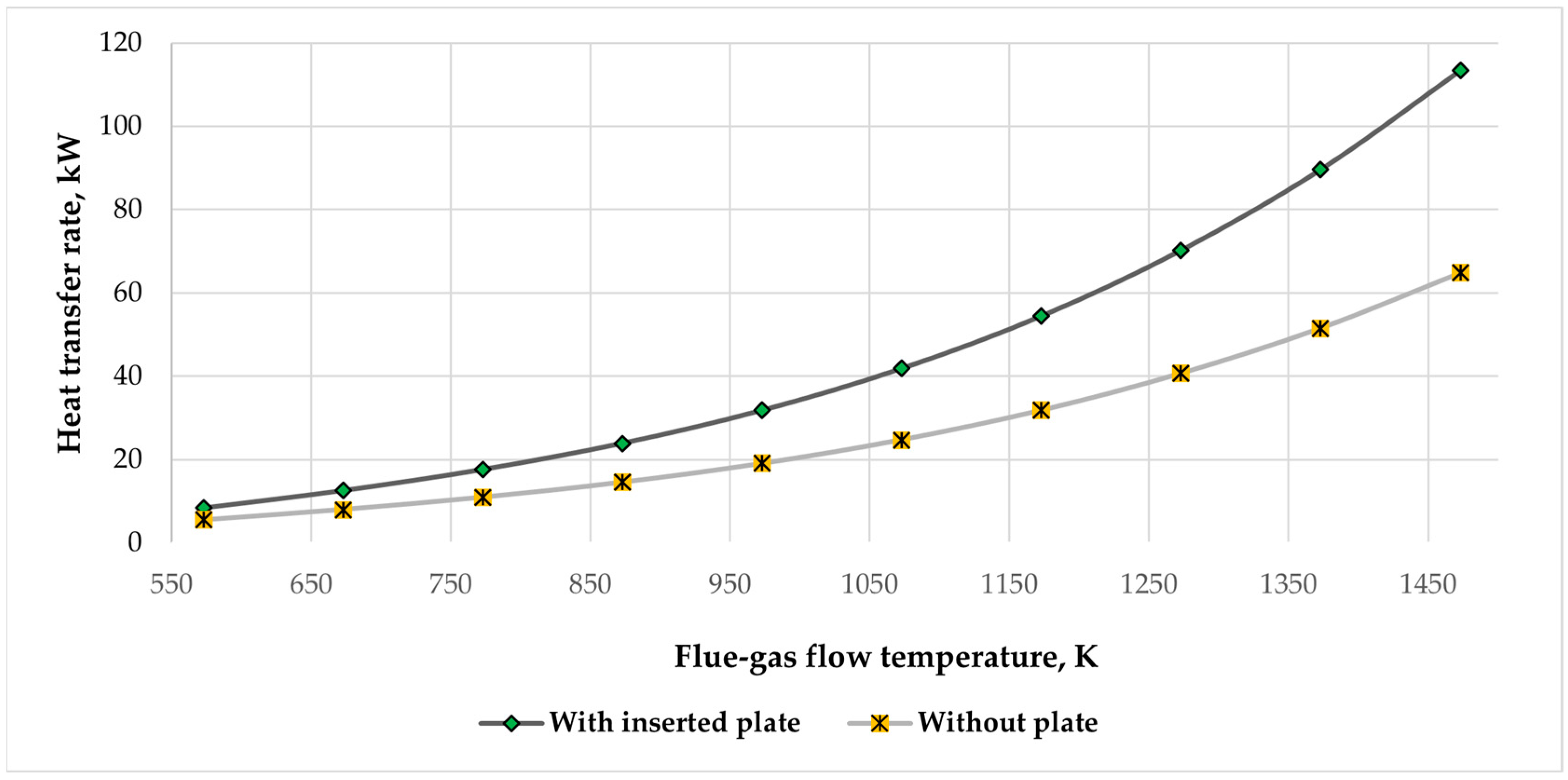
Figure 6 illustrates the dependency of heat transfer rate (W) on flue-gas flow temperature (K), comparing it in two cases: with an inserted radiation-intensifying plate and without a plate. The x-axis represents the flue-gas flow temperature in K, while the y-axis shows the corresponding heat transfer rate in W. The data clearly indicate that heat transfer rate increases with rising flue-gas flow temperature in both cases, following an exponential dependence. However, a significant enhancement in heat transfer is observed when a radiation-intensifying plate is inserted into the system. Across the entire temperature range, the configuration with the inserted plate consistently exhibits higher heat transfer values than without a plate. For instance, at approximately 1350 K, the heat transfer rate with the inserted plate exceeds 105,000 W. In contrast, the value without the plate remains around 65,000 W. From this, we can conclude that the heat transfer at the mentioned temperature increased by more than 60%. This significant change is due to the radiation-intensifying surface, where the hot flue-gas heats the plate, and it starts radiating. As we can see from the graph, the impact of radiation is perceived from ~600 K, but its influence increases as the flue-gas flow temperature increases. In conclusion, the calculation results support the hypothesis that inserting a plate into the heat exchange system significantly improves heat transfer efficiency over the examined temperature range.
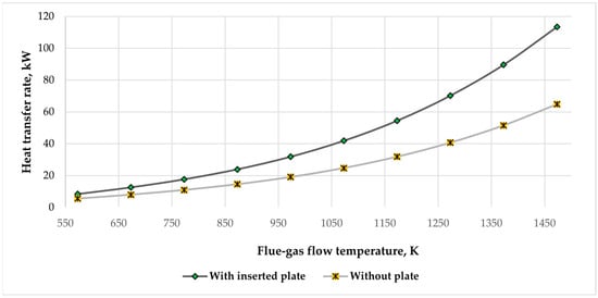
Figure 6.
Total heat transfer rate comparison when using a radiation-intensifying plate vs. without a radiation-intensifying plate.
These findings are relevant in applications involving high-temperature flue-gas flow systems, such as industrial heat exchangers, combustion chambers, and thermal energy recovery systems. The observed tendency provides insights into optimizing heat transfer performance by adjusting operational parameters such as flue-gas flow rate and temperature.
3.2. The Case of the Radiation-Intensifying Plate Is Positioned in the Pipe
Figure 7 illustrates the correlation between heat transfer rate and flue-gas flow temperature in a pipe fitted with a radiation-intensifying plate, showcasing the roles of various heat transfer mechanisms. The x-axis denotes the flue-gas flow temperature in kelvins, ranging from 560 K to 1460 K, while the y-axis represents the heat transfer rate in watts, peaking at 2500 W. The data reveal that total heat transfer rate, which includes radiation from flue-gas, convection, and radiation from the radiation-intensifying plate, significantly decreases as gas temperature declines, demonstrating the strong relationship between heat transfer efficiency and thermal conditions. Radiative heat transfer from flue-gas exhibits a similar downward trend and constitutes the largest share of the total heat transfer rate, especially at higher temperatures. In contrast, convective heat transfer is notably lower and diminishes with temperature, emphasizing its limited impact on the overall heat transfer process. The radiative contribution from the radiation-intensifying plate is also significant, particularly at elevated temperatures, indicating a notable performance in light of the thermal gradient. Figure 7 establishes that radiation, mainly from flue-gas, is the primary heat transfer mechanism at high temperatures. Conversely, at lower temperatures, convection’s role becomes more pronounced in sustaining the total heat transfer rate. These insights are crucial for the design of industrial tubular heat exchangers operating at high temperatures. Recognizing the dominance of radiative heat transfer above approximately 1000 K enables engineers to optimize exchanger surfaces and materials for maximum radiative efficiency. The continuous contribution of the radiation-intensifying plate indicates that such inserts can be tactically employed to improve performance without increasing surface area. Moreover, understanding the limited influence of convection at elevated temperatures can assist in avoiding over-sizing the system’s convective components, resulting in more compact and cost-efficient heat exchanger designs.
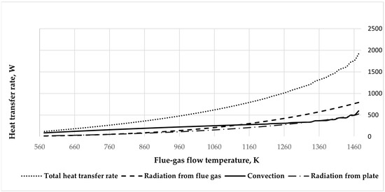
Figure 7.
Amount of heat transferred by different heat transfer methods.
3.2.1. Heat Transfer Rate Comparison at Different Temperatures of the Pipe Wall
Figure 8a–c provide a comprehensive analysis of the effect of pipe wall surface temperature on total heat transfer rate and the corresponding percentage increase in heat transfer under varying flue-gas flow temperatures. The four different cases of wall temperature are analyzed: 303 K, 333 K, 363 K, and 393 K, covering a flue-gas flow temperature range from approximately 1460 K to 560 K. Figure 8a,b illustrate the total heat transfer rate at different wall temperatures; it is evident that total heat transfer rate decreases with decreasing flue-gas temperature across all cases. This pattern highlights the essential role of the temperature gradient between the hot flue-gas and the pipe wall in governing radiative and convective heat transfer. While increased wall temperatures (Ts = 393 K) lead to a modest reduction in heat transfer rate compared to lower wall temperatures (Ts = 303 K), the resulting differences are minimal at elevated flue-gas temperatures but become increasingly significant as the gas temperature declines. Figure 8c quantitatively captures this difference by presenting the percentage increase in heat transfer rate when comparing the lowest and highest wall temperatures (393 K vs. 303 K). The results show an exponential rise in percentage gain as the gas temperature decreases. The percentage difference is minimal at the highest flue-gas temperatures (around 3–5%). Still, as the gas temperature drops below approximately 900 K, the influence of wall temperature becomes more substantial, with the heat transfer rate increase exceeding 40% at the lowest measured gas temperature (560 K). This behavior can be clarified by the decrease in the driving temperature gradient at higher wall temperatures, which suppresses radiative and convective transfer rates. However, the relative effect of increasing wall temperature becomes more significant at lower gas temperatures, where the absolute temperature difference between flue-gas and wall becomes less significant, leading to a substantial percentage gain in heat transfer rate. This effect can be explained by the fact that, although the absolute heat transfer rate is lower at reduced gas temperatures, the relative impact of wall temperature becomes more pronounced, leading to a significantly higher percentage increase.
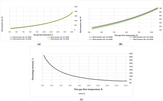
Figure 8.
Heat transfer rate comparison at different temperatures of the pipe wall. (a) Heat transfer rate comparison to varying temperatures of the pipe wall, (b) heat transfer rate comparison in different pipe wall temperatures (flue-gas flow temperature varies between 560 K and 1460 K), and (c) percentage increase in heat transfer rate, comparing 393 K vs. 303 K wall temperature.
3.2.2. Heat Transfer Rate Comparison in Different Spectral Emissivities of Flue-Gas Flow
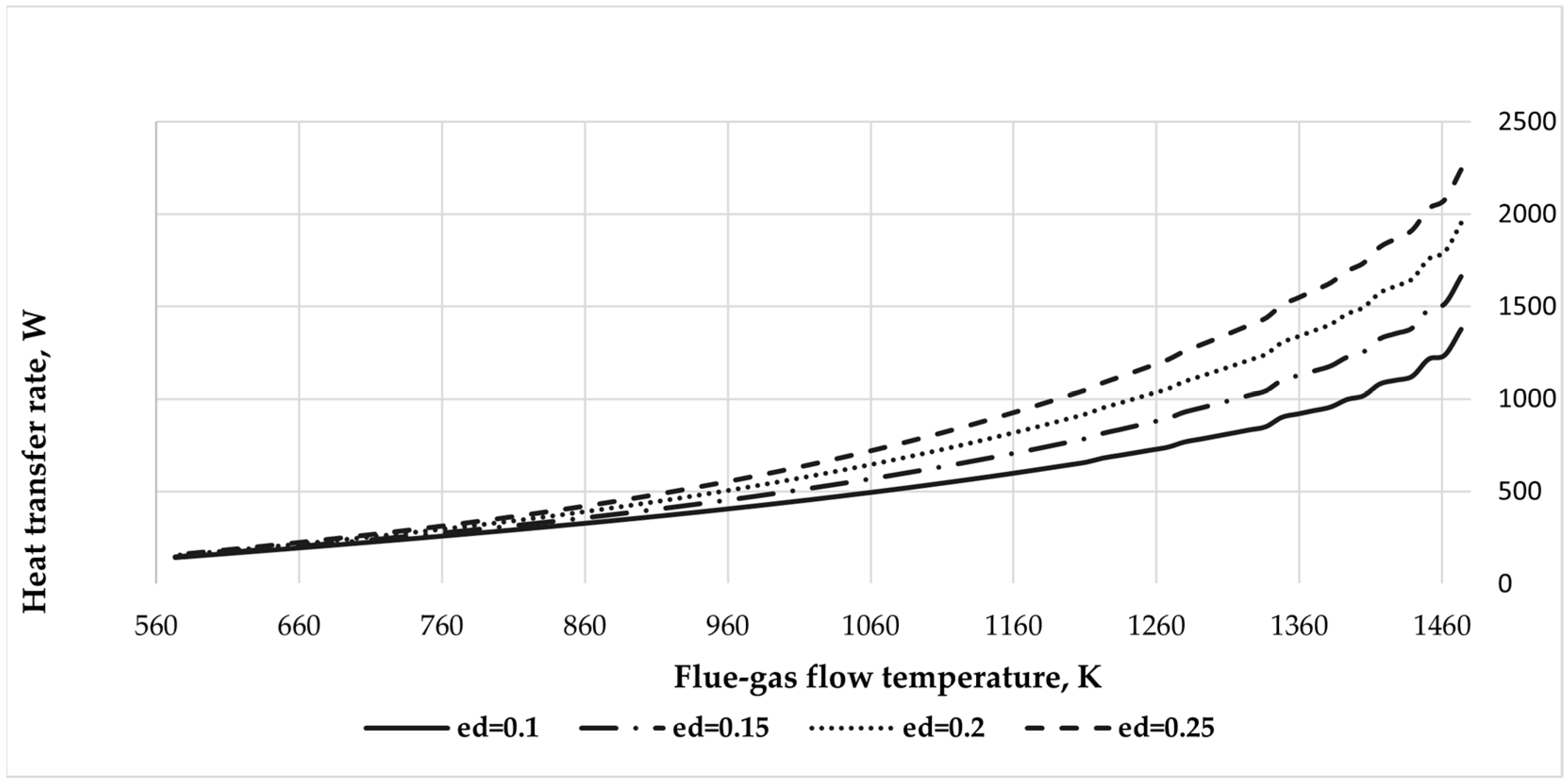
Figure 9 presents the effect of flue-gas spectral emissivity εd on the total heat transfer rate across a range of flue-gas flow temperatures. The x axis shows gas temperature in Kelvin, spanning from 560 K to 1460 K, while the y axis indicates total heat transfer rate in Watts, with values reaching up to 2500 W. The data include four distinct curves corresponding to emissivity values of 0.10, 0.15, 0.20, and 0.25. The results show that the total heat transfer rate decreases in the same pattern with decreasing flue-gas temperature for all considered emissivity values. This behavior indicates the strong dependence of radiative heat transfer on the fourth power of temperature, as the Stefan–Boltzmann law describes. Higher emissivity values result in significantly higher heat transfer rate at any flue-gas temperature. For example, when flue-gas temperatures rise above 1200 K, the heat transfer rate corresponding to εₑ = 0.25 significantly exceeds that for εₑ = 0.10. The divergence between the curves becomes more noticeable at higher flue-gas temperatures, indicating that the effect of emissivity on heat transfer intensifies with increasing thermal radiation potential. Conversely, at lower gas temperatures, the curves converge, and the influence of emissivity becomes less dominant. This is consistent with the reduced contribution of radiation at lower thermal levels, where convective mechanisms may become comparatively more relevant.
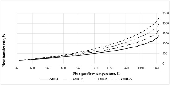
Figure 9.
Heat transfer comparison in different spectral emissivities of flue-gas flow.
3.2.3. Heat Transfer Rate Comparison in Different Body Spectral Emissivity of Pipe and Inserted Plate Material
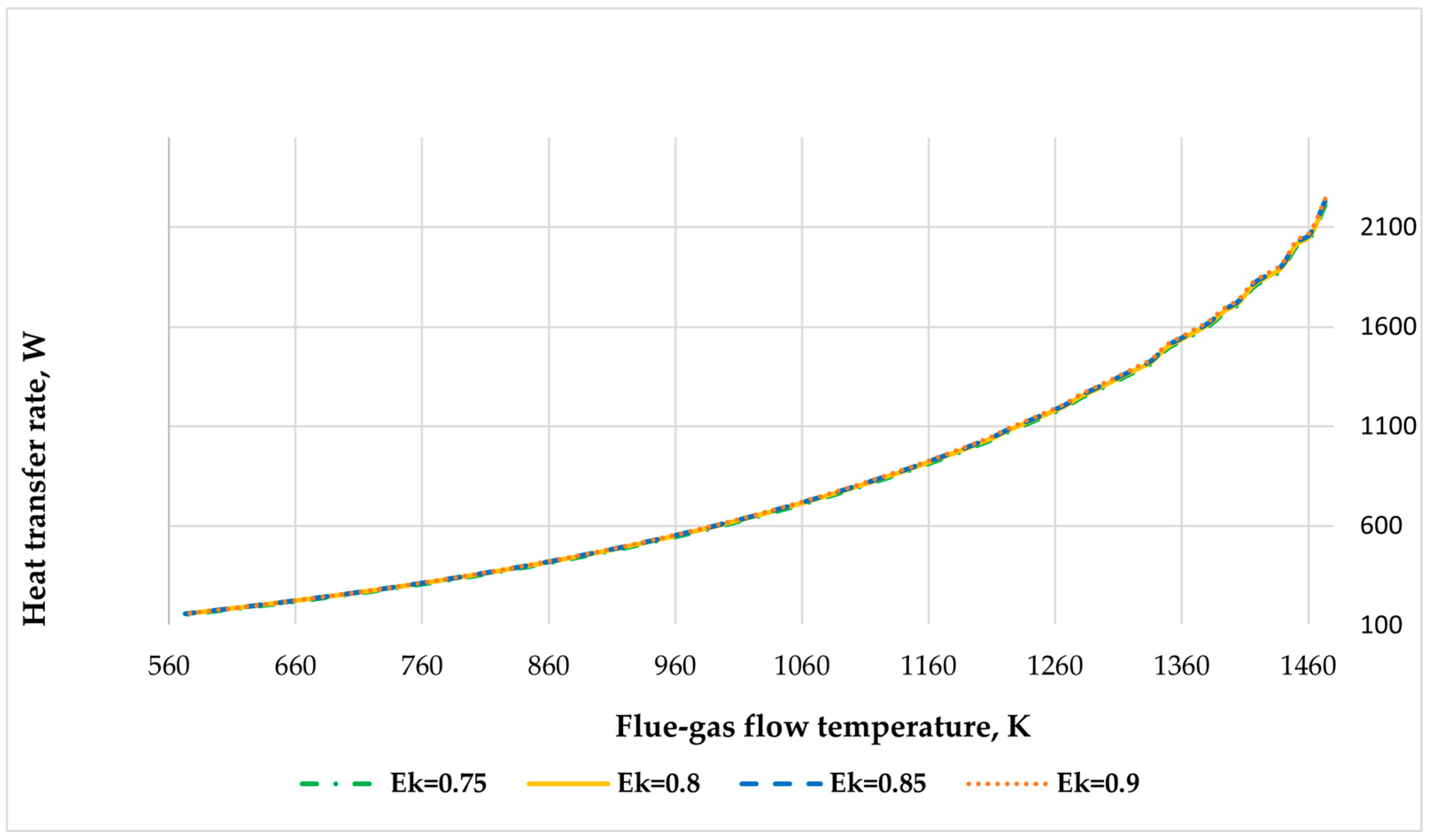
Figure 10 presents the relationship between flue-gas flow temperature (K) and heat transfer rate (W) for different emissivities (ε) of the surfaces of a pipe and an inserted plate. The x-axis shows the flue-gas flow temperature in kelvins, while the y-axis shows the corresponding heat transfer rate in watts. Four emissivity values are compared: ε = 0.75, 0.8, 0.85, and 0.9. The results indicate a clear correlation between flue-gas flow temperature and heat transfer rate. The heat transfer rate decreases significantly as the flue-gas flow temperature decreases, following a nonlinear correlation. This behavior is consistent across all considered emissivity values. Comparing the total heat transfer rate when the emissivity is 0.75 and 0.9, the values differ from 1.29% to 1.48%. Thus, it can be concluded that the emissivity of the pipe surface and the inserted plate do not significantly impact the total heat transfer rate. This graph demonstrates that while the emissivity of the surface materials has a minor effect on heat transfer rate, particularly at higher gas temperatures, the dominant factor affecting heat transfer in this configuration is the flue-gas flow temperature. The results suggest that optimizing emissivity does not significantly influence thermal performance, but controlling temperature is more critical for maximizing heat transfer.
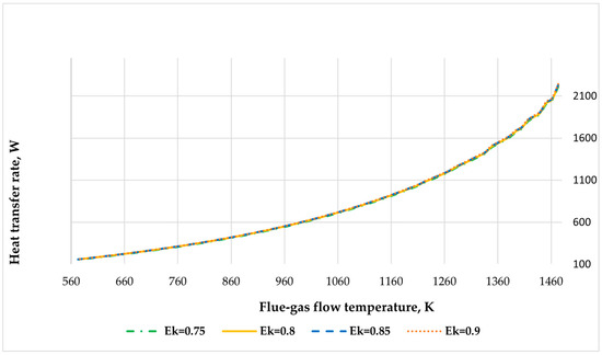
Figure 10.
Heat transfer rate comparison in different body spectral emissivity of the pipe and the inserted plate material.
3.2.4. Correlation of Reynolds and Nusselt Numbers with Geometrical Ratios
Figure 11 presents the Reynolds number (Re) variation as a function of the dimensionless geometrical parameter l/d for two cases: with and without a radiation-intensifying plate. The x-axis represents the ratio of characteristic dimensions, while the y-axis indicates the Reynolds number, characterizing the flow regime within the system. In both configurations, the Reynolds number increases with increasing l/d, which suggests that larger cross-sectional dimensions show higher flow velocities or reduced viscous effects. However, there is a striking difference between the two cases under consideration. The system without the radiation-intensifying plate consistently exhibits higher Reynolds numbers across the entire range of l/d values. This decrease in Re when the plate is inserted represents that the plate creates additional flow resistance or disrupts the velocity profile, lowering the overall flow rate. At the maximum investigated l/d value (~160), the Reynolds number exceeds 11,000 without the plate, whereas it only reaches approximately 6700 when the plate is present. These results demonstrate that inserting a radiation-intensifying plate leads to noticeable changes in flow dynamics, particularly in reducing the Reynolds number, which could shift the flow toward a more laminar regime depending on operating conditions.
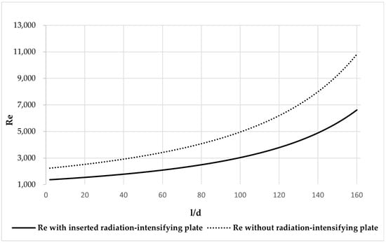
Figure 11.
Variation of the Reynolds number with and without a radiation-intensifying plate.
Figure 12a,b illustrate the Nusselt number (Nu) variation concerning the dimensionless parameter l/d, for configurations with and without an inserted radiation-intensifying plate. These figures provide insights into the convective heat transfer performance under varying geometric ratios. As shown in Figure 12a, the Nusselt number shows an increasing tendency with rising l/d for both examined configurations. Nevertheless, the research without the radiation-intensifying plate consistently gives higher Nu values throughout the entire l/d interval. This disparity becomes particularly significant at higher l/d values, where Nu exceeds 28 in the absence of the plate, while remaining below 20 when the plate is present. Including the radiation-intensifying plate appears to disrupt the flow and increase hydraulic resistance, which diminishes the efficiency of convective heat transfer, as indicated by the reduced Nusselt numbers. Figure 12b provides a magnified view of the lower l/d region (0–30), where the differences in Nu are more subtle. In this range, the Nusselt number with the inserted radiation-intensifying plate initially decreases to Nu = 6.09, at which point l/d equals 26. Afterwards, the Nu values start to increase. In contrast, the configuration without the plate gradually increases Nu with increasing l/d. These results suggest that the inserted plate causes local flow instabilities, leading to oscillations in Nu, particularly noticeable for l/d < 30.
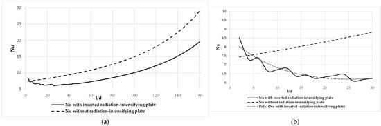
Figure 12.
Nu number comparison when using and without radiation-intensifying plate: (a) variation of Nu number with and without the radiation-intensifying plate; (b) variation of Nu number with and without the radiation-intensifying plate when l/d varies between 0 and 30.
3.2.5. Comparison of the Overall Heat Transfer Rate Increase
Figure 13a presents the total heat transfer rate (W) as a function of the dimensionless length-to-diameter ratio (l/d). Two cases are compared: with and without using a radiation-intensifying plate. The results show that using the plate significantly increases the total heat transfer rate across the entire range of l/d values. As l/d increases, the total heat transfer rate decreases in both cases; however, the configuration with the radiation-intensifying plate consistently exhibits higher heat transfer rate values. This demonstrates the effectiveness of the inserted plate in enhancing heat transfer, particularly in regions closer to the channel inlet.
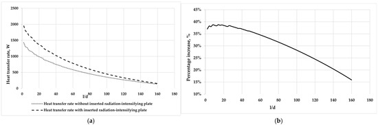
Figure 13.
Total heat transfer rate comparison when using a radiation-intensifying plate vs. without a radiation-intensifying plate in the tube. (a) Total heat transfer rate comparison when using vs. without radiation-intensifying plate; (b) percentage increase in heat transfer rate when using a radiation-intensifying plate in the tube.
Figure 13b illustrates the relative percentage increase in heat transfer rate due to using the radiation-intensifying plate, again plotted against the l/d ratio. The data indicate that the enhancement effect is most pronounced at lower l/d ratios, reaching up to approximately 40%, and gradually diminishes with increasing l/d. Despite the decreasing trend, the use of the plate yields a substantial improvement in heat transfer performance even at larger l/d values, indicating its potential benefit for longer tubes or channels.
3.3. Summary of the Results
The results provide a comprehensive understanding of how various thermal and geometric parameters influence heat transfer performance in systems with and without a radiation-intensifying plate. The calculations demonstrated that flue-gas flow temperature is the dominant factor affecting total heat transfer rate, while flue-gas flow rate and wall temperature also play significant, though secondary, roles. The insertion of a radiation-intensifying plate significantly enhances radiative heat transfer, especially at higher flue-gas temperatures, but simultaneously introduces flow resistance, reducing convective effectiveness, as reflected by lower Reynolds and Nusselt numbers. The influence of material emissivity was found to be minimal for the pipe and plate surfaces, yet more pronounced for the flue-gas itself at elevated temperatures. Additionally, the analysis of dimensionless parameters revealed that the radiation-intensifying plate changes flow behavior and convective dynamics, particularly in the transitional l/d range. A comparison of total heat transfer rates for configurations with and without the radiation-intensifying plate across different l/d ratios demonstrates the plate’s ability to enhance heat transfer, particularly in the inlet region of the channel. The greatest improvement is observed at smaller l/d ratios, reaching around 40%. Yhe effect remains notable even at higher l/d values, indicating that the radiation-intensifying plate provides consistent benefits across a broad range of geometrical configurations.
These results establish a solid foundation for further analysis and interpretation. The following section discusses the physical implications of these findings, evaluates potential trade-offs between radiative and convective performance, and outlines recommendations for thermal system optimization in practical engineering applications.
4. Discussion and Key Findings
The results of this study highlight the dominant role of flue-gas flow temperature in determining total heat transfer rate, with both convective and radiative contributions increasing significantly at high temperatures. Integrating a radiation-intensifying plate led to an over 60% improvement in heat transfer at high temperatures due to enhanced radiation, notably when the gas temperature exceeded 1000 K. However, this enhancement introduced additional flow resistance, reducing the Reynolds and Nusselt numbers and compromising convective efficiency, especially at higher l/d ratios.
A local minimum in the Nusselt number observed around l/d ≈ 26 suggests transitional flow behavior and boundary layer disturbances caused by the plate. As the flow developed downstream, Nu values increased again, highlighting the influence of geometric design on flow stability.
At lower flue-gas temperatures, wall temperature effects became more pronounced. An increase from 303 K to 393 K resulted in an over 40% gain in heat transfer rate at 560 K, emphasizing the importance of surface temperature control in low-temperature regimes. This relative impact is greater when the absolute heat transfer rate is low, making wall temperature a critical factor under part-load or fluctuating conditions.
Furthermore, gas spectral emissivity had a notable impact on radiative heat transfer, while variations in surface emissivity showed only marginal effects (<1.5%). These findings suggest that optimization should focus on gas-phase radiative properties for high-temperature applications.
Overall, the study demonstrates the potential of radiation-enhancing components in improving thermal system performance and identifies key trade-offs in convective behavior that must be addressed during design.
5. Conclusions and Future Scope
This study presented a comprehensive analysis of radiative and convective heat transfer in gas-heated systems with and without a radiation-intensifying plate, based on a systematic literature review that helped identify key knowledge gaps and define the scope of the analytical investigation. The results revealed that flue-gas flow temperature is the key parameter influencing total heat transfer, with exponential growth in heat transfer rate observed as temperature increases. Inserting a radiation-intensifying plate significantly improved radiative heat transfer, resulting in over a 60% increase in heat transfer rate at elevated temperatures. However, this enhancement was accompanied by increased flow resistance, as evidenced by reduced Reynolds and Nusselt numbers, indicating a lower convective heat transfer.
Wall temperature and flue-gas flow emissivity also affected heat transfer, particularly under lower wall temperature conditions, where their relative influence became more significant because of the higher temperature gradient. The analysis of dimensionless parameters (Nu and Re) revealed transitional flow behavior and local instabilities, emphasizing the importance of geometric optimization when incorporating radiation-enhancing components.
These findings are significant for developing industrial applications like heat exchangers, combustion chambers, and waste heat recovery systems. These systems require enhanced thermal efficiency, and these findings could be one of the passive heat transfer enhancement methods. The combined results of the systematic literature review and analytical analysis emphasize the complicated character of coupled heat transfer mechanisms in high-temperature systems.
Future work will focus on experimental and numerical validation of the presented results, essential for verifying model accuracy and further analyzing flow and thermal behavior under real operating conditions. These experimental studies will support model refinement and contribute to developing practical design guidelines for thermal systems utilizing radiation-enhancing elements.
Author Contributions
Writing—original draft preparation, visualization, investigation, formal analysis, methodology, J.M.; project administration, supervision, R.J.; funding acquisition, A.B.; methodology, data curation, L.P.; methodology, K.B. All authors have read and agreed to the published version of the manuscript.
Funding
This research received no external funding.
Data Availability Statement
The original contributions presented in this study are included in the article. Further inquiries can be directed to the corresponding author(s).
Conflicts of Interest
The authors declare no conflicts of interest.
Nomenclature
| Ad | absorption coefficient of the flue-gas flow | Re | Reynolds number |
| C0 | absolutely black body radiation coefficient, W/m2·K4 | SLR | systematic literature review |
| d | characteristic dimension of channel, m | Tgasflow | flue-gas temperature, K |
| dek | characteristic dimension of channel, m | Tshield | temperature of inserted shield, K |
| f | cross-sectional area of the channel, m2 | Tw | temperature of wall, K |
| Fs | wall surface area, m2 | w | velocity of flow gas, m/s |
| Fshield | surface area of shield, m2 | α | heat transfer coefficient, W/K |
| Fshield | surface area of shield, m2 | β | thermal expansion coefficient of the fluid volume, 1/K |
| g | gravity acceleration, m/s2 | Δ | difference |
| Gr | Grashof number | ε | spectral emissivity of the wall |
| l | length of pipe, m | εd | spectral emissivity of the gas flow |
| Nu | Nusselt number | εl | multiplier for laminar flow |
| P | the perimeter of the channel, m | εt | emissivity of the surface system |
| Prf | Prandtl number of flue-gas flow | εt | multiplier for turbulent flow |
| Prp | Prandtl number of wall | λ | thermal conductivity coefficient, W/m∙K |
| Qcon | amount of heat received by convection from the flue-gas flow, W | σ0 | Stefan–Boltzmann constant, W/m2·K4 |
| Qr | amount of heat received by radiation from the flue-gas flow, W | υ | kinematic viscosity, m2/s |
| Qrshield | amount of heat radiated from shield to the walls, W | φshield | angular coefficient of radiation from the shield |
References
- Darbandi, T.; Risberg, M.; Westerlund, L. Enhancing particle segregation in stem wood combustion flue gas wet scrubbers: Experimental investigation of operational conditions. Case Stud. Therm. Eng. 2024, 64, 105427. [Google Scholar] [CrossRef]
- Ilona, J.; Choate, W.T.; Davidson, A. Waste Heat Recovery. Technology and Opportunities in US Industry; BCS, Inc.: Laurel, MD, USA, 2008. [Google Scholar]
- Suanes, G.; Bolonio, D.; Cantero, A.; Yenes, J.I. Principles for the Design of a Biomass-Fueled Internal Combustion Engine. Energies 2024, 17, 1700. [Google Scholar] [CrossRef]
- Belousov, A.; Lushpeev, V.; Sokolov, A.; Sultanbekov, R.; Tyan, Y.; Ovchinnikov, E.; Shvets, A.; Bushuev, V.; Islamov, S. Experimental Research of the Possibility of Applying the Hartmann–Sprenger Effect to Regulate the Pressure of Natural Gas in Non-Stationary Conditions. Processes 2025, 13, 1189. [Google Scholar] [CrossRef]
- Zhien, C.Y.; Al-attab, K.A.; Enagi, I.I.; Mohamed, A.R.; Badruddin, I.A.; Kamangar, S.; Baig, M.A.A. Numerical evaluation of low-grade producer gas flow and combustion characteristics in swirl combustor. Case Stud. Therm. Eng. 2025, 69, 106008. [Google Scholar] [CrossRef]
- Shank, K.; Tiari, S. A review on active heat transfer enhancement techniques within latent heat thermal energy storage systems. Energies 2023, 16, 4165. [Google Scholar] [CrossRef]
- Nitturi, L.K.; Kapu, V.K.S.; Gugulothu, R.; Kaleru, A.; Vuyyuri, V.; Farid, A. Augmentation of heat transfer through passive techniques. Heat Transf. 2023, 52, 4422–4449. [Google Scholar] [CrossRef]
- Kakaç, S.; Pramuanjaroenkij, A. Review of convective heat transfer enhancement with nanofluids. Int. J. Heat Mass Transf. 2009, 52, 3187–3196. [Google Scholar] [CrossRef]
- Garg, M.O.; Nautiyal, H.; Khurana, S.; Shukla, M.K. Heat transfer augmentation using twisted tape inserts: A review. Renew. Sustain. Energy Rev. 2016, 63, 193–225. [Google Scholar]
- Marzouk, S.A.; Al-Sood, M.M.A.; El-Said, E.M.; Younes, M.M.; El-Fakharany, M.K. A comprehensive review of methods of heat transfer enhancement in shell and tube heat exchangers. J. Therm. Anal. Calorim. 2023, 148, 7539–7578. [Google Scholar] [CrossRef]
- Deshmukh, P.W.; Kasar, S.V.; Prabhu, S.V. A comprehensive compendium on passive augmentation techniques for enhancement of single-phase heat transfer coefficients in heat exchanger tubes under laminar and turbulent flow conditions. Heat Transf. Eng. 2023, 44, 530–579. [Google Scholar] [CrossRef]
- Xin, Z.; Chen, J.; Gu, S.; Li, K. Passive enhancement of heat transfer in a microchannel by an adjoint system of cylinder and flexible beam. Numer. Heat Transf. Part A Appl. 2022, 82, 765–787. [Google Scholar] [CrossRef]
- Sagar, J.P.; Ankith, B.; Rao, P.S.; Reddy, P.R.; Elipey, M.K. A review on heat transfer enhancement methods for a heat exchanger. In Proceedings of the 8th Annual International Seminar on Trends in Science And Science Education (AISTSSE) 2021, Medan, Indonesia, 3 November 2022; Volume 2648. [Google Scholar]
- Pavel, B.I.; Mohamad, A.A. An experimental and numerical study on heat transfer enhancement for gas heat exchangers fitted with porous media. Int. J. Heat Mass Transf. 2004, 47, 4939. [Google Scholar] [CrossRef]
- Hong, Y.; Du, J.; Li, Q.; Xu, T.; Li, W. Thermal-hydraulic performances in multiple twisted tapes inserted sinusoidal rib tube heat exchangers for exhaust gas heat recovery applications. Energy Convers. Manag. 2019, 185, 271. [Google Scholar] [CrossRef]
- Neshumayev, D. Experimental and Numerical Investigation of Combined Heat Transfer Enhancement Technique in Gas-Heated Channels; Tallinn University of Technology Press: Tallinn, Estonia, 2005. [Google Scholar]
- Morelli, A.; Tognoli, M.; Ghidoni, A.; Najafi, B.; Rinaldi, F. Reduced FV modelling based on CFD database and experimental validation for the thermo-fluid dynamic simulation of flue gases in horizontal fire-tubes. Int. J. Heat Mass Transf. 2022, 194, 123033. [Google Scholar] [CrossRef]
- Jasinski, P.B. Numerical Study of Heat Transfer Intensification in a Circular Tube Using a Thin, Radiation-Absorbing Insert. Part 2: Thermal Performance. Energies 2021, 14, 4533. [Google Scholar] [CrossRef]
- Dewey, A.; Drahota, A. Introduction to Systematic Reviews: Online Learning Module Cochrane Training. 2016. Available online: https://www.cochrane.org/learn/courses-and-resources/interactive-learning/module-1-introduction-conducting-systematic-reviews (accessed on 15 March 2025).
- Cooke, A.; Smith, D.; Booth, A. Beyond PICO: The SPIDER tool for qualitative evidence synthesis. Qual. Health Res. 2012, 22, 1435–1443. [Google Scholar] [CrossRef]
- Cambridge Dictionary. Volume 2025, No. 02.11. Available online: https://dictionary.cambridge.org/dictionary/english/eligibility (accessed on 10 May 2025).
- Ma, X.; Hu, S.; Hu, W.; Luo, Y.; Cheng, H. Experimental investigation of waste heat recovery of thermoelectric generators with temperature gradient. Int. J. Heat Mass Transf. 2022, 185, 122342. [Google Scholar] [CrossRef]
- Vahidifar, S.; Banihashemi, S. Experimental and numerical evaluation of heat transfer enhancement by internal flow excitation. Int. J. Therm. Sci. 2023, 192, 108395. [Google Scholar] [CrossRef]
- Bisetto, A.; Del Col, D.; Schievano, M. Fire tube heat generators: Experimental analysis and modeling. Appl. Therm. Eng. 2014, 78, 236. [Google Scholar] [CrossRef]
- Azari, A.; Derakhshandeh, M. An experimental comparison of convective heat transfer and friction factor of Al2O3 nanofluids in a tube with and without butterfly tube inserts. J. Taiwan Inst. Chem. Eng. 2015, 52, 31. [Google Scholar] [CrossRef]
- Awais, M.; Bhuiyan, A.A. Heat transfer enhancement using different types of vortex generators (VGs): A review on experimental and numerical activities. Therm. Sci. Eng. Prog. 2018, 5, 524. [Google Scholar] [CrossRef]
- Morelli, A.; Ghidoni, A.; Lezzi, A.M.; Noventa, G. Integrated approach based on surrogate optimization and CFD for the design of helical turbulators. Therm. Sci. Eng. Prog. 2023, 39, 101741. [Google Scholar] [CrossRef]
- Subirana, A.M.; Solano, J.P.; Herrero-Martín, R.; García, A.; Pérez-García, J. Mixed convection phenomena in tubes with wire coil inserts. Therm. Sci. Eng. Prog. 2023, 42, 101839. [Google Scholar] [CrossRef]
- Sharifi, K.; Sabeti, M.; Rafiei, M.; Mohammadi, A.H.; Ghaffari, A.; Asl, M.H.; Yousefi, H. A good contribution of computational fluid dynamics (CFD) and GA-ANN methods to find the best type of helical wire inserted tube in heat exchangers. Int. J. Therm. Sci. 2020, 154, 106398. [Google Scholar] [CrossRef]
- Louahdi, M.; Salhi, J.; Essaouini, H.; Zarrouk, T.; Lahlaouti, M.L. Three-dimensional analysis for optimizing thermo-hydrodynamic performance of heat exchangers with perforated semi-circular inserts. Case Stud. Therm. Eng. 2024, 60, 104611. [Google Scholar] [CrossRef]
- Javadi, S.M.; Banihashemi, S. Study of thermal performance and optimization of city gas station heaters equipped with turbulator in the fire tube section. Therm. Sci. Eng. Prog. 2022, 37, 101573. [Google Scholar] [CrossRef]
- Kamaei, R.; Izadi, M.; Altnji, S.; Majdoub, F.; Hajjar, A.; Alqurashi, F.; Mohamed, M.H.; Hamida, M.B.B. All-around review on applying passive strategies to improve heat exchanger performance using inserts and turbulators applied in thermal storage. Int. Commun. Heat Mass Transf. 2024, 159, 108234. [Google Scholar] [CrossRef]
- Neshumayev, D.; Ots, A.; Laid, J.; Tiikma, T. Experimental investigation of various turbulator inserts in gas-heated channels. Exp. Therm. Fluid Sci. 2004, 28, 877. [Google Scholar] [CrossRef]
- Neshumayev, D.; Tiikma, T. Radiation heat transfer of turbulator inserts in gas heated channels. Heat Transf. Res. 2008, 39, 403–412. [Google Scholar] [CrossRef]
- Murthy, H.M.S.; Hegde, R.N.; Rai, N. Effect on performance of a CTHE by using twisted tapes and Al2O3 nanofluids: An experimental study and correlation development. Sādhanā 2024, 49, 205. [Google Scholar] [CrossRef]
- Abd-Elhady, M.S.; Malayeri, M.R. Mitigation of Soot Deposition in Exhaust Gas Recirculation Coolers Using a Spiral Insert. Aerosol Sci. Technol. 2014, 48, 184. [Google Scholar] [CrossRef]
- Qudah, S.A.; Radwan, A.; El-Sharkawy, I.I. Experimental analysis of heat transfer in a circular tube fitted with new twisted tape insert with rings using response surface methodology. Int. J. Heat Fluid Flow 2025, 112, 109713. [Google Scholar] [CrossRef]
- Abbas, A.; Ayub, Z.; Ayub, A.; Li, W.; Khan, S. Comparing single-phase thermal hydraulic performance of a right and left turn twisted tape insert in a tube. J. Braz. Soc. Mech. Sci. Eng. 2021, 43, 123. [Google Scholar] [CrossRef]
- Ifraj, N.F.; Fahad, M.K.; Tahsin, S.H.; Haque, M.R.; Haque, M.M. Numerical investigation of the thermal performance optimization inside a heat exchanger tube using different novel combination of perforations on Y-shaped insert. Int. J. Therm. Sci. 2023, 194, 108583. [Google Scholar] [CrossRef]
- Maleki, N.M.; Pourahmad, S.; Tavousi, E.; Perera, N.; Talebizadehsardari, P.; Keshmiri, A. Thermal-frictional behavior of solid magnetic strip turbulator and helical coiled wire turbulator inside a double tube heat exchanger. Int. Commun. Heat Mass Transf. 2025, 161, 108406. [Google Scholar] [CrossRef]
- Ifraj, N.F.; Akter, F.; Fahad, M.K.; Ahmed, D.H. Thermal-hydraulic performance enhancement with minimum entropy generation of a heat exchanger using fidget spinner vortex generators. Int. Commun. Heat Mass Transf. 2025, 162, 108610. [Google Scholar] [CrossRef]
- Khoshvaght-Aliabadi, M.; Akbari, M.H.; Hormozi, F. An empirical study on vortex-generator insert fitted in tubular heat exchangers with dilute Cu–water nanofluid flow. Chin. J. Chem. Eng. 2016, 24, 728. [Google Scholar] [CrossRef]
- Sharma, B. Effect of flow structure on heat transfer in compact heat exchanger by using finite thickness winglet at acute angle. J. Therm. Eng. 2017, 3, 1149–1162. [Google Scholar] [CrossRef]
- Keshari, V.; Maiya, M.P. Design and investigation of hydriding alloy based hydrogen storage reactor integrated with a pin fin tube heat exchanger. Int. J. Hydrogen Energy 2018, 43, 7081. [Google Scholar] [CrossRef]
- Zhao, Y.; Lu, M.; Li, Y.; Wang, Y.; Ge, M. Numerical investigation of an exhaust thermoelectric generator with a perforated plate. Energy 2022, 263, 125776. [Google Scholar] [CrossRef]
- Al-haidari, S.R.; Al-obaidi, A.R. Evaluation of hydraulic thermal flow and heat performance augmentation in a 3D tube fitted with varying concavity dimple turbulator configurations. Heat Transf. 2024, 54, 420. [Google Scholar] [CrossRef]
- Banihashemi, S.; Assari, M.; Javadi, S.; Vahidifar, S. The Effect of Flow Excitation with Stationary and Rotating Obstacles in a Heat Exchanger Tube on Thermal–Hydraulic Characteristics. Iran. J. Sci. Technol. Trans. Mech. Eng. 2022, 46, 465–480. [Google Scholar] [CrossRef]
- Zhang, J.M.; Sutton, W.H.; Lai, F.C. Enhancement of heat transfer using porous convection-to-radiation converter for laminar flow in a circular duct. Int. J. Heat Mass Transf. 1997, 40, 39–48. [Google Scholar] [CrossRef]
- Plotnikov, L.; Osipov, L. The Influence of Gas-Dynamic Non-Stationarity of Air Flow on the Heat Transfer Coefficient in Round and Triangular Straight Pipes with Different Turbulence Intensities. Appl. Sci. 2024, 14, 7758. [Google Scholar] [CrossRef]
- Rinik, R.A.; Bhuiyan, A.A.; Karim, M.R. Enhancement of heat transfer using elliptical twisted inner pipe with convergent conical ring turbulator for turbulent flow in double pipe heat exchanger. Int. J. Therm. Sci. 2025, 210, 109558. [Google Scholar] [CrossRef]
- Salman, Z.; Kadhim, Z.; Khalaf, K. Numerical study of helical tape inserts for air to oil double pipe heat exchanger. J. Mech. Eng. Res. Dev. 2021, 44, 207–220. [Google Scholar]
- Güngör, A.; Khanlari, A.; Sözen, A.; Variyenli, H.I. Numerical and experimental study on thermal performance of a novel shell and helically coiled tube heat exchanger design with integrated rings and discs. Int. J. Therm. Sci. 2022, 182, 107781. [Google Scholar] [CrossRef]
- Mei, B.; Abed, A.M.; Patel, P.; Kulshreshta, A.; Ayed, H.; Mouldi, A.; Mahariq, I. A numerical investigation for heat transfer enhancement possibility for a novel perforated twisted hyperbolic turbulator (PTHT) inside a heated tube. Case Stud. Therm. Eng. 2024, 65, 105666. [Google Scholar] [CrossRef]
- Banihashemi, S.; Assari, M.; Javadi, S.; Vahidifar, S. Study the effect of innovative active and passive methods on thermal characteristics and turbulent flow behaviour in a heat exchanger pipe. J. Therm. Anal. Calorim. 2024, 149, 777–797. [Google Scholar] [CrossRef]
- Pulin, A.; Laptev, M.; Kortikov, N.; Barskov, V.; Roschenko, G.; Alisov, K.; Talabira, I.; Gong, B.; Rassokhin, V.; Popovich, A.; et al. Numerical Investigation of Heat Transfer Intensification Using Lattice Structures in Heat Exchangers. Energies 2024, 17, 3333. [Google Scholar] [CrossRef]
- Assari, M.; Banihashemi, S.; Setareh, M.; Joudakinia, M. Investigating the Performance and Thermal Characteristics of Turbulent Flow in a Heat Exchanger Tube with Gridded Oval Slant Inserts. Iran. J. Sci. Technol. Trans. Mech. Eng. 2024, 48, 629–645. [Google Scholar] [CrossRef]
- Karami, A.; Ranjbar, B.; Rahimi, M.; Mohammadi, F. Novel hybrid neuro-fuzzy model to anticipate the heat transfer in a heat exchanger equipped with a new type of self-rotating tube insert. Eur. Phys. J. E 2022, 45, 92. [Google Scholar] [CrossRef] [PubMed]
- Wang, S.; Yang, L.; Su, Z.; Song, J.; Liu, S.; Li, X. Research progress on boiling heat transfer of nanofluids with emphasis on IVR-ERVC strategy. Therm. Sci. Eng. Prog. 2023, 39, 101716. [Google Scholar] [CrossRef]
- Hukkeri, K. VDI Heat Atlas: With 1011 Figures and 539 Tables; Springer: Berlin/Heidelberg, Germany, 2010. [Google Scholar]
- Gimbutis, G.; Kajutis, K.; Krukonis, V. Šiluminė Technika; Mokslas: Vilnius, Lithuania, 1993. [Google Scholar]


Disclaimer/Publisher’s Note: The statements, opinions and data contained in all publications are solely those of the individual author(s) and contributor(s) and not of MDPI and/or the editor(s). MDPI and/or the editor(s) disclaim responsibility for any injury to people or property resulting from any ideas, methods, instructions or products referred to in the content. |
© 2025 by the authors. Licensee MDPI, Basel, Switzerland. This article is an open access article distributed under the terms and conditions of the Creative Commons Attribution (CC BY) license (https://creativecommons.org/licenses/by/4.0/).