Article

Environmental Impact Assessment of Heat Storage System in Rock-Bed Accumulator

1
Department of Bioprocess Engineering, Power Engineering and Automation, Faculty of Production and Power Engineering, University of Agriculture in Kraków, 30-149 Kraków, Poland
2
Department of Microbiology and Biomonitoring, University of Agriculture in Krakow, 30-059 Kraków, Poland
*
Author to whom correspondence should be addressed.
Energies 2025, 18(13), 3360; https://doi.org/10.3390/en18133360
Submission received: 3 May 2025 / Revised: 19 June 2025 / Accepted: 24 June 2025 / Published: 26 June 2025

Abstract

The use of a rock-bed accumulator for a short-term heat storage and air exchange in a building facility is an economical and energy-efficient technological solution to balance and optimize the energy supplied to the facility. Existing scientific studies have not addressed, as yet, the environmental impacts of using a rock bed for heat storage. The purpose of the research is the environmental life cycle assessment (LCA) of a heat storage system in a rock-bed accumulator supported by a photovoltaic installation. The boundaries of the analyzed system include manufacturing the components of the storage device, land preparation for the construction of the accumulator, the entire construction process, including transportation of materials, and its operation in cooperation with a horticultural facility (foil tunnel) during one growing season, as well as the photovoltaic installation. The functional unit in the analysis is 1 square meter of rock-bed accumulator surface area. SimaPro 8.1 software and Ecoinvent database were used to perform the LCA, applying the ReCiPe model to analyze environmental impact. The analysis showed the largest negative environmental impact occurs during raw materials extraction and component manufacturing (32.38 Pt). The heat stored during one season (April to October) at a greenhouse facility reduces this negative impact by approx. 7%, mainly due to the reduction in the use of fossil fuels to heat the facility. A 3 °C increase in average air temperature results in an average reduction of 0.7% per year in the negative environmental impact of the rock-bed thermal energy storage system.

1. Introduction

As a result of the growing demand for electricity and heat, the EU Member States have set the goal of implementing the circular economy (CE) system by 2030, the essential elements of which include reducing the consumption of natural resources, e.g., by replacing traditional fuels with renewable energy sources (RES) and eco-design [1,2]. In addition, the global economy, especially in the EU, is moving toward sustainable, green and economical energy use [3,4]. The depletion of natural resources and the growing importance of RES resulted in the development of energy storage technologies perceived as the key challenge nowadays. There are many methods of energy storage, from the simplest and the most popular systems, e.g., Absorbed Glass Mat (AGM) batteries and domestic hot water (DHW) tanks, to more elaborate systems such as pumped storage power stations [5,6].
Systems for energy storage from RES in DHW tanks involves heating domestic hot water with solar panels or an electric heater powered by the energy generated by a photovoltaic (PV) system or a domestic wind turbine. Moreover, the surplus of electricity from PV and a domestic wind turbine can be transferred to the distribution system operator and “stored” there [7,8,9]. Apart from RES systems that convert solar energy, there are also ground source heat pumps, allowing energy to be stored in the ground or groundwater. During the heating season, these devices supply buildings with central heating (CH) and DHW by extracting energy from the environment. In summer, on the other hand, the heat pump cools the building facility based on a reverse cycle. The energy extracted from the building can be stored in the ground or groundwater, to be reused in the winter season [10,11].
Rechargeable batteries such as lead–acid, valve-regulated lead–acid, lead–carbon, lithium-ion, lithium iron phosphate, and sodium-ion are the commonly known and used batteries for electricity storage. Secondary cells, or rechargeable batteries, store and release electricity through electrochemical reversibility. In the charging process, electricity is converted into chemical energy, which can later be recovered, converting it back into electricity. Batteries of this type are characterized by a limited lifespan (charging cycles) [12]. Other less-known batteries of this type include flow batteries, the so-called vanadium flow batteries. They differ from classic batteries in construction and the principle of operation. Electricity is stored in flow batteries in the form of chemical compounds dissolved in a liquid, which allows increasing capacity using a larger tank [13,14]. Compared to the previously mentioned electrochemical energy storage system, supercapacitors are characterized by a lower energy density. As a result, the initial installation cost is higher, but it is possible to achieve energy densities comparable to batteries. Their main advantage, however, is a much longer life cycle, up to 100 times longer than that of lithium-ion and lead–acid batteries [5,15].
Liquid air is also used as one of the alternative methods for energy storage. Liquid air energy storage (LAES) works by sucking in ambient air, which is then compressed and cooled to the temperature of −196 °C, resulting in its condensation. The condensed air is stored in insulated, low-pressure tanks. During discharge, electricity is recovered by pumping, evaporating, and expanding the liquid air stream through a set of turbines [16,17]. This solution is characterized by the absence of significant site constraints, as the power generation cycle can be driven by available heat sources such as waste heat or ambient temperature, thus avoiding CO2 emissions. In addition, the storage does not contain harmful chemicals, making it an environmentally safe solution. The disadvantages of this solution include low frequency of energy storage and low efficiency of storage compared to, e.g., pumped storage power stations [16,17].
Pumped thermal energy storage (PTES) systems use electrical grid and heat pumps to alternately heat and cool the material in tanks, thus creating an energy resource which can be reused to generate electricity when needed. The PTES systems are characterized by their long life cycles (up to 30 years), lack of geographic restrictions, elimination of fossil fuels, and possibility to integrate with traditional fossil fuel-based power plants [16,18].
Pumped hydro energy storage (PHES) plants are definitely the largest electricity storage facilities. Hydropower plants are designed to store excess electricity and return it to the grid at times of increased demand. In the course of electricity generation, water flows by gravity through turbines located between the upper and lower reservoirs. PHES operation is based on the cyclic charging and discharging processes. The total energy storage efficiency of PHES, taking into account the charging and discharging processes, ranges from 70 to 87% [16,19]. The lifespan of such energy storage facilities is estimated to be approx. 60 years. The primary function of hydropower plants is to maintain the balance of power within an electrical grid. The construction of such facilities depends on several critical factors, including access to a water source and an electrical grid [16,19].
Energy storage technologies are continuously improved, and their development allows for mitigating the problems caused by unstable weather-dependent RES energy production [20]. Modern advancements in this field support sustainable energy storage and use, which are essential for achieving climate neutrality goals. Energy storage also enables flexible response to the variable nature of RES operation in electric power systems [5]. To balance energy production and energy demand effectively, it is necessary to develop and implement various storage technologies. They allow storing excess energy and releasing it at times of increased demand. A lesser-known, yet innovative, method of energy storage is using the system based on a rock bed, which can work with, e.g., greenhouses for plant cultivation, where often excess heat generated during a sunny day has to be dissipated outside the facility [21,22] and thus wasted irretrievably.
The idea behind storing thermal energy in a rock-bed heat accumulator is to suck in warm air resulting from increased temperature in the facility. The heated air is directed through a system of perforated ventilation ducts to the rock bed, where the heat is stored. At the time of increased heat demand (during the night in the case of greenhouses), the stored heat is returned to the facility via perforated pipes. In domestic conditions, this solution is employed in greenhouses and foil tunnels, helping to reduce reliance on non-renewable energy sources, especially during colder periods [21,22].
Life cycle assessment (LCA) computer software is used to assess the environmental impact of new products, investments, and equipment, especially when examining their life cycle holistically. The commonly known environmental impact assessment tools are SimaPro, GaBi, OneClickLCA, openLCA, CAALA, and Umberto [23]. These software programs use specific models to predict the environmental impact of products or processes, calculating emissions expressed through various impact and damage indicators. Tools such as SimaPro and GaBi are considered comprehensive for the full life cycle assessment, as they offer not only a broad database but also advanced analysis options [4,23]. This software enables continuous improvement and assessment of the impact of current methods for electrical and thermal energy storage.
Díaz-Ramírez et al. [24], using SimaPro 8 software, version Analyst 8.5.0.0 and the ReCiPe 2016 midpoint model, assessed the potential benefits of recycling steel, copper, aluminum, and plastics in battery production. Umberto LCA+ and the CML-2001 method was used by Blume et al. [25] to assess the environmental impact of an industrial so-called vanadium flow battery from a technical and electrochemical perspective. Wickerts et al. [26] conducted an environmental analysis of sodium-ion batteries using OpenLCA (GreenDelta, version 1.10.3) and the ReCiPe 2016 model, excluding the end-of-life stage. Open LCA was also used by Peters et al. [27] to assess sodium-ion batteries with a capacity of 1 kWh and an assumed lifespan of 2000 charge cycles. An analysis of the environmental impact of one of the largest energy storage systems, i.e., PHES, was conducted by Zhang et al. [28], focusing on the system construction and operation stages. However, to the best of our knowledge, no environmental analyses of rock-bed accumulators for heat storage have been reported in the literature so far.
Previous studies have shown that rock-bed accumulators can effectively store heat meeting the thermal demand of facilities within a certain range of ambient air temperatures [21]. Kurpaska et al. [21] proved that the application of this type of system has a beneficial effect on the energy balance of facilities such as greenhouses and foil tunnels, outperforming standard heating systems in this regard and resulting in economic benefits. Assessing the environmental impact of a heat accumulator remains the key issue.
The purpose of this study is to assess the environmental benefits of a heat storage system in a rock-bed accumulator. The analysis covers nearly the entire life cycle of the system (excluding the end-of-life phase), including its production, assembly, transportation of materials, and the use phase, i.e., repeated charging and discharging (heat exchange). The key contribution of this research is the application of life cycle analysis (LCA), which enables a comprehensive assessment of the environmental impacts related to the implementation of a thermal energy storage system in greenhouses.

2. Materials and Methods

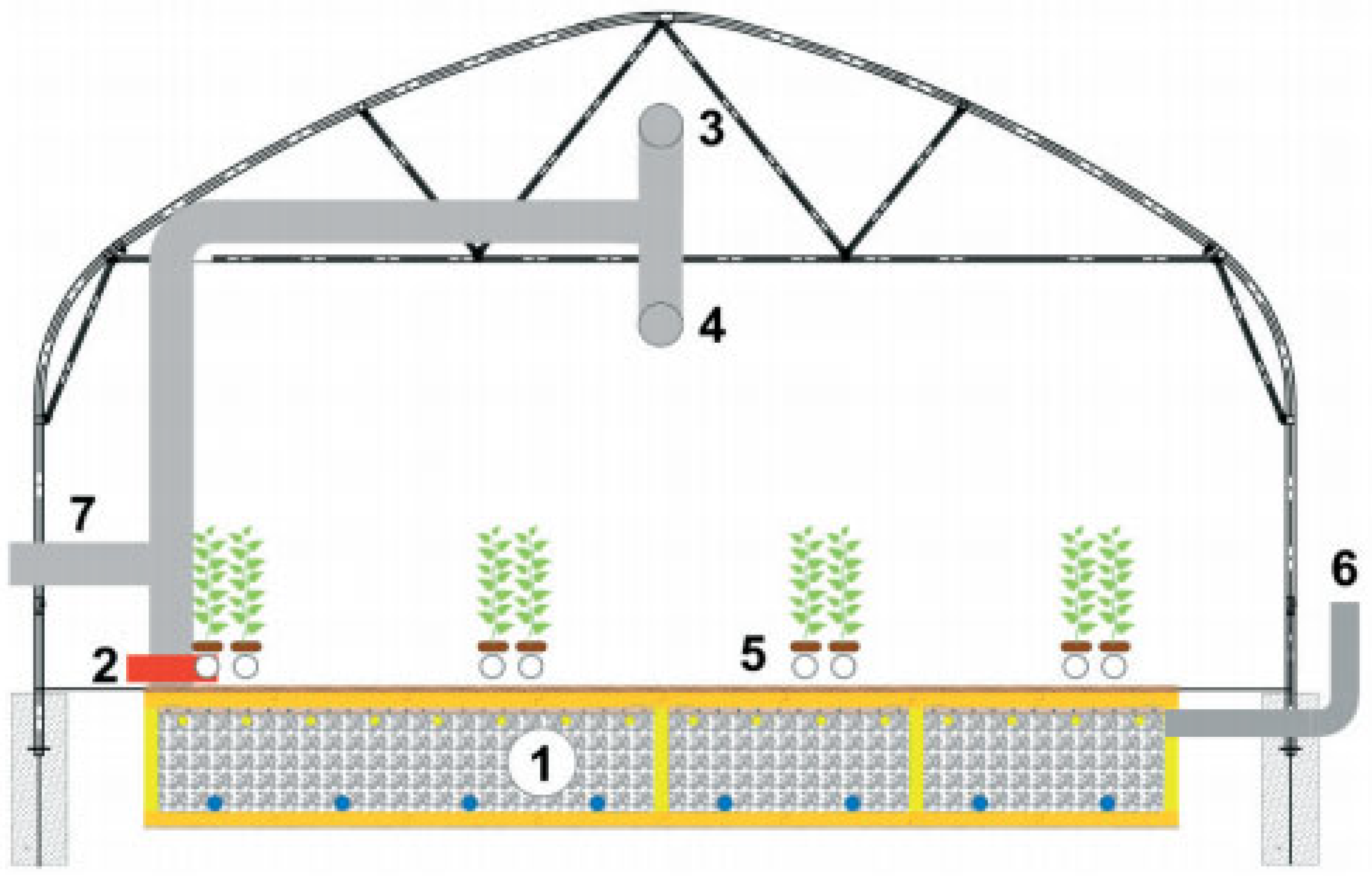
2.1. Characteristics of the Analyzed Object

The analyzed rock-bed heat accumulator, which serves as a heat storage in a foil tunnel, is located in Krakow (Poland) (N 50.07966; E 19.86766). The average air temperature at this location, from April to October, is about 15 °C, and insolation reaches 955 kWh·m−2·year−1 [29]. Average precipitation, from April to October, is 380 mm, with 77 rainy days. The average wind speed fluctuates around 2.8 m·s−1, and the approximate number of days with snowfall is 3 [30].
A rock-bed accumulator is made of stones resembling the ballast used in the construction of railroad embankments (Figure 1). The analyzed accumulator consists of four segments of 18.7 m2 each and a rock layer 0.7 m deep. The entire device is insulated with polystyrene foam. Sensors installed in the accumulator and the facility transmit information about temperature and humidity within the accumulator and the foil tunnel to the computer control system. Warm air at the top of the tunnel is drawn in and forced into the bed using a fan system, thereby charging the accumulator. When the greenhouse temperature drops significantly, the accumulator can be discharged: outside air passes through the bed, heats up, and is then transferred into the greenhouse. This process is automatic, and the heat stored in the bed can be utilized even several days after loading. Additionally, the accumulator can be used to cool the plants during periods of rapid temperature increase inside the greenhouse in the morning. A damper control system, which manages the position of dampers directing airflow, is an integral part of the accumulator, alongside the ventilation ducts, rock bed, and fans. During periods of high sunlight, a PV system supplies power to auxiliary equipment such as the fan.

2.2. Scope of Analyses
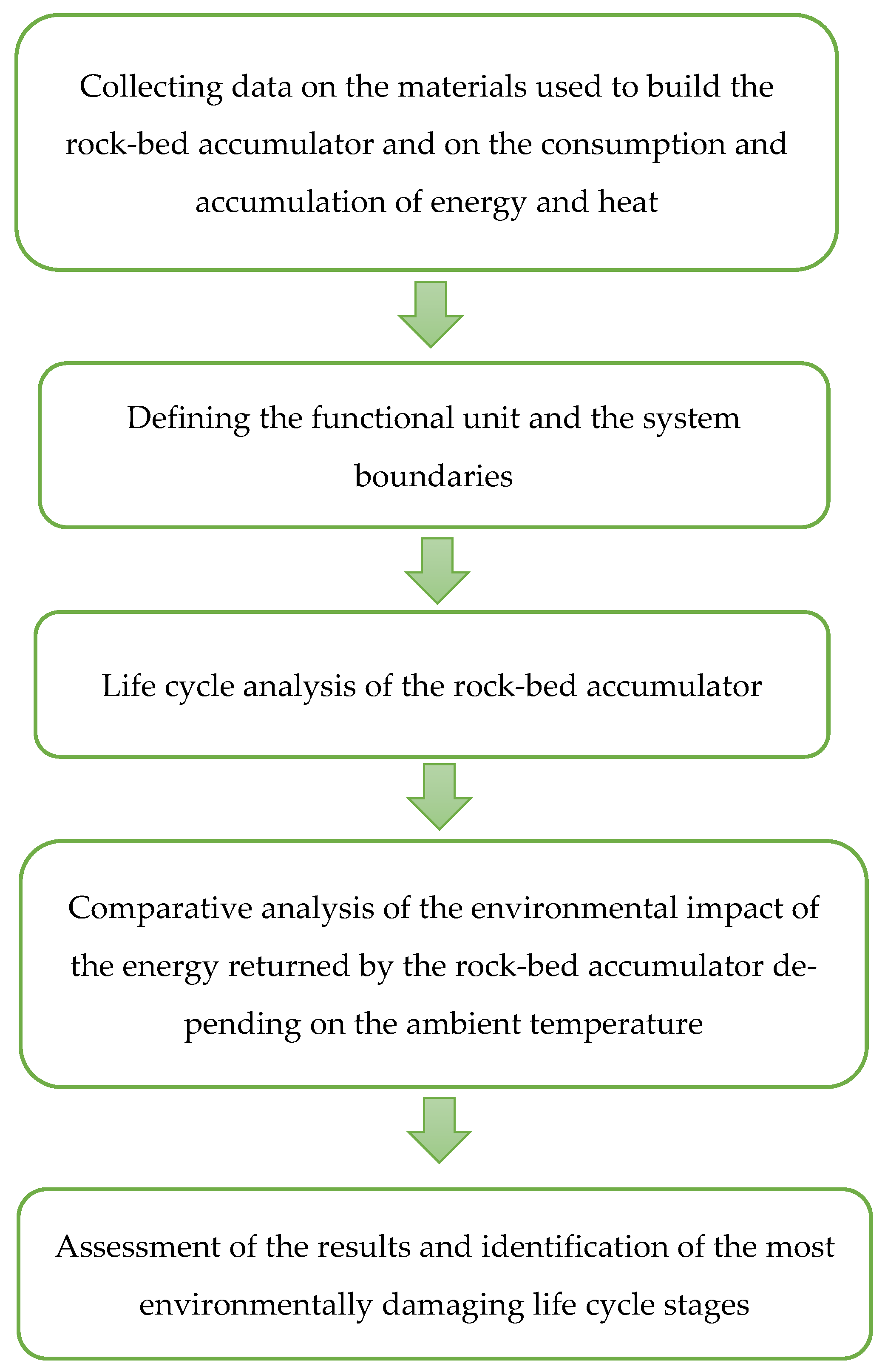
The schematic diagram of the conducted analysis is illustrated in Figure 2. As part of the life cycle analysis in accordance with ISO 14040 [32] and ISO 14044 [33], the functional unit and system boundaries were defined, allowing for understanding which processes and stages are important in assessing the environmental impact of the accumulator [34]. In addition, the study presents a comparative analysis of the device’s environmental performance, taking into account the impact of changing average air temperature (from −3 to +3 °C) during one season (April to October) of rock-bed accumulator operation.

2.3. LCA Modelling

2.3.1. Purpose, Scope, Functional Unit, System Boundaries, and Life Cycle Inventory

The purpose of the study is the environmental impact assessment of a heat storage system in a rock-bed accumulator cooperating with a greenhouse facility and a PV installation. The analysis covers the production of the accumulator, its installation, transportation of materials, and the use phase (one season), including the stored thermal energy usage. The functional unit in this analysis was adopted based on LCA studies in the construction sector, described in the publications by Zsembinszki et al. [35] and Llantoy et al. [36] as 1 m2 of rock-bed accumulator surface area used through 1 season of work (April to October).
The LCA methodology requires a precise definition of the system boundaries, which allows identifying the key inputs and outputs, such as raw materials and energy, in the subsequent phases of the process. The life cycle analysis of a rock-bed accumulator covers obtaining raw materials needed to manufacture the accumulator, their transportation to the site, and site preparation, as well as the energy consumption and accumulation data.
The conducted analyses did not address the environmental impacts exerted by the construction of the greenhouse facility, focusing instead on aspects related to the rock-bed heat accumulator itself. The boundaries of the analyzed system also do not take into account the environmental impacts associated with the demolition of the foil tunnel, growing plants, and the disassembly of the accumulator (end-of-life phase). These elements were excluded for the following reasons: the rock-bed heat accumulator is still in the operational phase and has not yet been dismantled; the foil tunnel and crop cultivation are not integral parts of the thermal storage system but rather components of the agricultural setup, which was not within the scope of this analysis.
The analysis is focused on an environmental impact assessment covering the extraction of raw materials, their processing to produce the accumulator parts and components, transportation of materials and finished components to the project site, earthworks, and one season of accumulator operation. In addition, the electricity generated by the PV installation, which works with the heat storage (providing electricity to power the fan system sucking warm air into the accumulator), is included within the system boundaries. The range of rock-bed heat accumulator construction data used is illustrated in Table 1, Table 2 and Table 3.
The life cycle inventory (LCI) covers quantitative data on the consumption of raw materials, other materials, and fuel, as well as electricity and heat within the boundaries of the analyzed system. The values used in the environmental analysis were obtained during an interview with the facility manager. The data on the consumption of materials for the construction of the rock-bed accumulator were expressed in kilograms per square meter of the heat storage area [kg·m−2]. The transportation of materials and the construction equipment work was determined in ton-kilometer per square meter [tkm·m−2], and the amount of thermal energy obtained from the accumulator in kilowatt-hours per square meter [kWh·m−2]. The collected data were then entered into SimaPro 8.1 (PRé Sustainability BV, Amersfoort, The Netherlands) for further analyses.
The mechanism of the rock-bed accumulator operation consists in storing and releasing thermal energy, which reduces temperature fluctuations and improves the internal microclimate. Tests were carried out at the facility over a 7-month time interval (April–October), and a total of 801 cycles were analyzed (418 charging and 383 discharging cycles of the accumulator). Details of the conducted research, the measurement apparatus as well as the control algorithm were presented by Kurpaska et al. [37]. Basically, the control principle was as follows: if the difference between the sucked air temperature and the bed temperature, or the difference between the bed temperature and the outlet temperature, exceeded 2K, then an accumulator charging cycle or a discharging cycle followed, respectively. In the charging cycle, heat was stored in the accumulator, while in the discharging cycle, heat from the accumulator was directed inside the tunnel.
The equipment installed in the greenhouse heating system is powered by electricity from two sources: PV panels and the electrical grid. The installation of PV panels allows the facility to be partially independent of traditional energy sources, thereby reducing greenhouse gas emissions and other pollutants. The PV power plant, with a total capacity of 14 kWp, is located on the premises of the Faculty of Production and Power Engineering at the University of Agriculture in Krakow, near the rock-bed accumulator covered by this study. It was built as a research project aimed at comparing three types of panels (monocrystalline silicon, polycrystalline silicon, and CIGS) and currently supplies power to the university facilities, with surplus energy sold back to the grid. The capacity of the PV installation was sufficient to meet the electricity demand during daytime, when the accumulator was being charged. Conversely, discharging processes that occur at night require energy supplied from the grid. Therefore, in the analysis, it was assumed that the energy needed to charge the accumulator comes from the PV system, while energy for discharging is supplied from the grid. Table 4 and Table 5 present information on the accumulated and discharged heat from the rock-bed heat accumulator, as well as the electricity obtained to operate the system from both the PV installation and the grid.

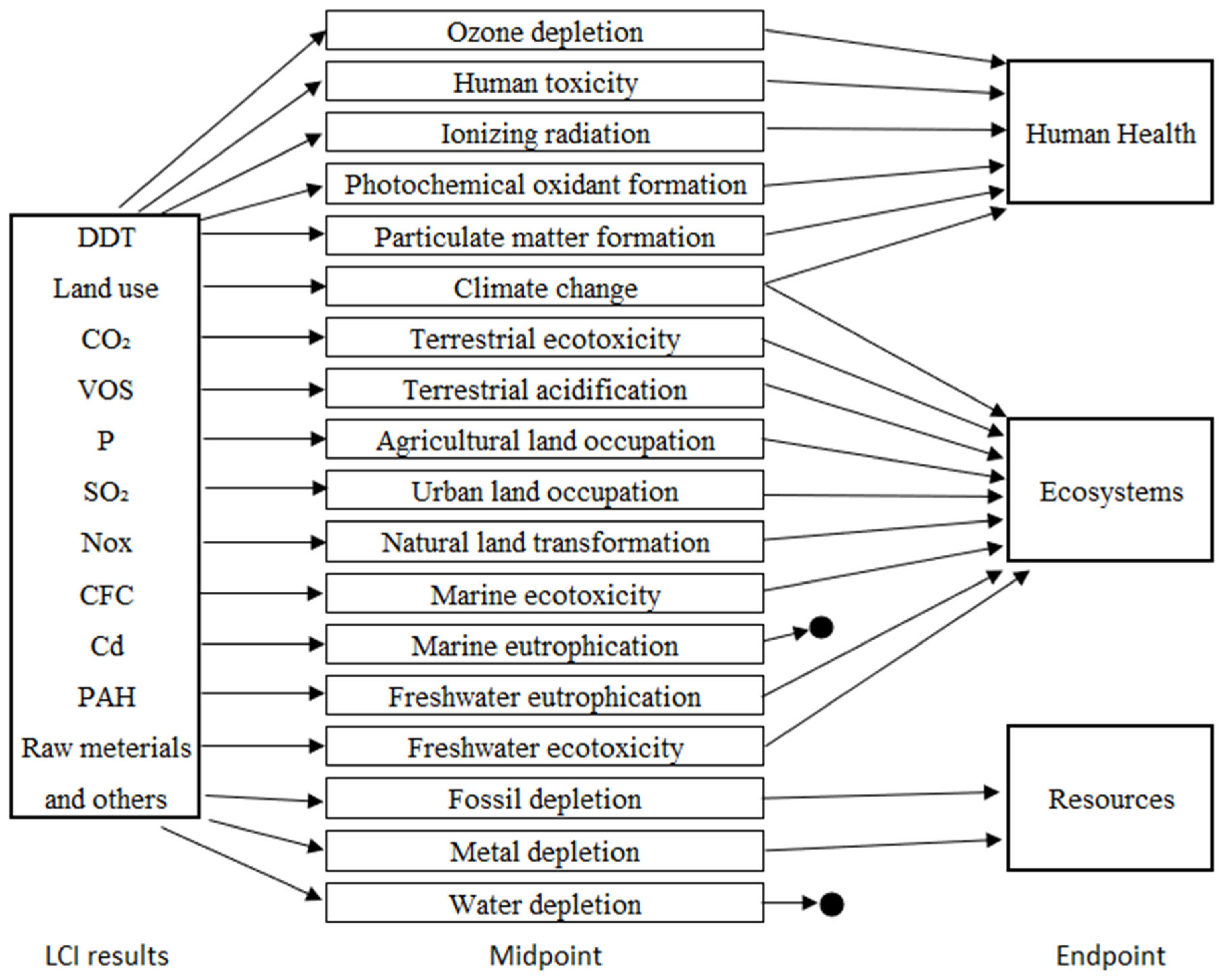
2.3.2. Environmental Impact Assessment

The life cycle assessment was carried out using SimaPro (PRé Sustainability BV, Amersfoort, The Netherlands) and the Ecoinvent 3.0 database. The ReCiPe 2016 model, which assesses environmental impact at two levels: midpoint and endpoint (Figure 3), was used to perform the analysis. The model was developed in 2008 by RIVM, Radboud University Nijmegen, Leiden University and PRé Consultants. It combines previous methods, such as Eco-Indicator 99 and CML, to create consistent assessment boundaries.
The ReCiPe 2016 Midpoint (H) V1.12 model was applied to assess environmental impact using 18 impact categories (consumption and emissions of various substances into the environment). Midpoint indicators refer to specific environmental problems occurring along the cause–effect pathway, such as climate change, acidification, eutrophication, or toxicity. They are characterized by a strong relationship to environmental flows and lower levels of uncertainty. The ReCiPe 2016 Midpoint (H) model reflects the hierarchical perspective, which assumes an intermediate position in terms of time horizon and cultural outlook. This approach provides a balanced and widely used framework for LCA studies. The impact score Im for each midpoint category m was calculated using the following governing equation [38]:
I m = i = 1 n E i · C F i , m
where
  • Im—total impact in midpoint category m (e.g., kg CO2 eq, kg 1,4-DB eq, kg SO2 eq);
  • Ei—quantity of elementary flow (e.g., emission or resource use) i (e.g., kg);
  • CFi,m—characterization factor linking flow i to impact category m;
  • n—total number of elementary flows considered.
For example, in the climate change midpoint category (Global Warming Potential, GWP), the calculation is [38]:
G W P = m E G H G m · C F E , m
where
  • EGHGm—total emissions of greenhouse gas m (e.g., CO2, CH4, N2O);
  • CFE,m—characterization factor converting emissions of gas m into CO2-equivalent (where for GWP100 (for a 100-year horizon): CO2 = 1, CH4 = 25 and N2O = 298).
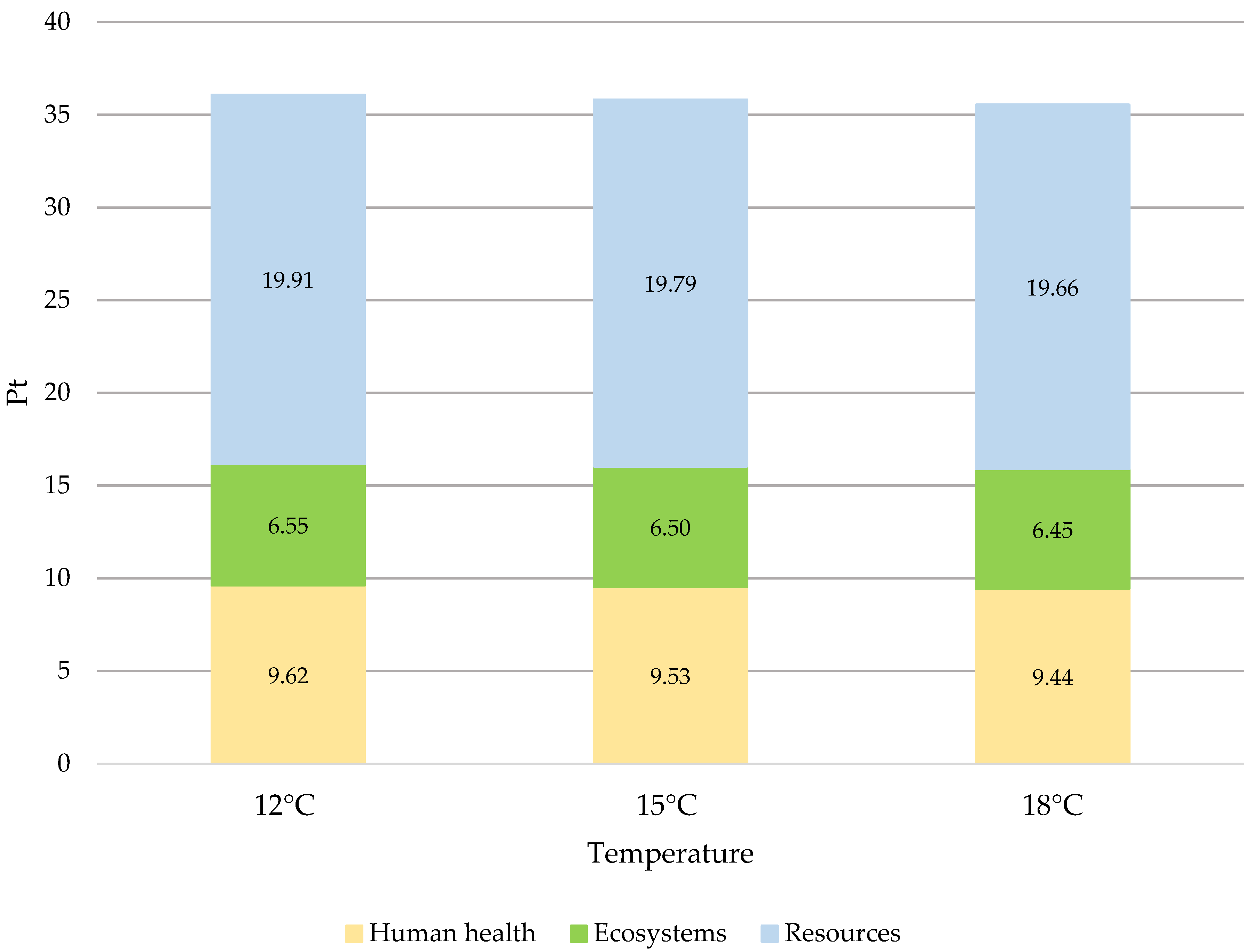
All calculations were performed within SimaPro using default characterization factors provided by the ReCiPe 2016 Midpoint (H) method.
The ReCiPe 2016 Endpoint model, in turn, takes into account three assessment endpoints, i.e., impacts on human health, ecosystems, and resources. Although the endpoint allows for a simplified and more understandable interpretation of the LCIA results, it is associated with a higher level of uncertainty due to the aggregation of effects in the modeling [39,40,41]. The ecopoint (Pt), also referred to as the “person equivalent” (PE), is the master unit in the ReCiPe model. One Pt represents one thousandth of the annual environmental impact of an average European [41].

3. Results

The conducted LCA analysis indicated that the operation of the rock-bed accumulator results in negative environmental impact, having assumed its operation for one season. The rocks used in the accumulator, insulation materials, and ventilation system components are the sources of greenhouse gas emissions and pollutants from their production and transportation processes. Installation of the system requiring the use of construction equipment also generates additional environmental burdens, mainly related to emissions from fossil fuel consumption. During the accumulator operation phase, the installed fans are powered by electricity, which also contributes to the increased negative impact. The use of PV panels only partially compensates for the electricity demand obtained from the electrical grid.
On the other hand, the system reduces primary energy consumption due to efficient heat accumulation and release, which lowers the need for the greenhouse-intensive heating in colder weather and its cooling in summer periods. At the same time, the use of PV in the studied facility reinforces the environmental effect by reducing the dependence on fossil-fuel-based energy.
The conducted life cycle analysis (LCA) indicated that in a single cycle of operation (one season), the energy absorbed and returned by the rock-bed accumulator does not fully compensate for the emissions and other environmental impacts associated with the manufacturing, transportation, and assembly processes of this device. The findings show that the environmental benefits provided by the accumulator are clear; however, they are not enough to offset its total environmental impact (Table 6 and Figure 4).
Based on the life cycle analysis (Table 6), a conclusion can be drawn that the phase of obtaining materials needed for the construction of the rock-bed heat accumulator has the greatest negative impact on the environment of all the phases analyzed. The production of these materials significantly burdens such impact categories as climate change (320.4 kg CO2 eq), metal depletion (55.5 kg Fe eq), human toxicity (61.069 kg 1,4-DB eq), and fossil depletion (87.5 kg oil eq). In turn, the impact categories such as agricultural land occupation, marine ecotoxicity, freshwater ecotoxicity, and freshwater eutrophication are most affected by the electricity obtained from the electrical grid.
CFC, the characterization factor for ozone layer depletion, accounts for the destruction of the stratospheric ozone layer by anthropogenic emissions of ozone-depleting substances. 1,4-DB, the characterization factor of human toxicity and ecotoxicity, accounts for the environmental persistence (fate), accumulation in the human food chain (exposure), and toxicity (effect) of a chemical. NMVOC, the unit of human health ozone formation potential, is the characterization factor determined from the change in the intake rate of ozone due to change in emission of precursors. And kBq U235, the characterization factor of ionizing radiation, accounts for the level of exposure for the global population [38].
As shown by the analysis of the ReCiPe 2016 Endpoint model (Figure 4), the environmental impact resulting from manufacturing 1 m2 of a rock-bed heat accumulator amounts to 32.38 Pt. The second most significant source of negative impact is the consumption of electricity from the grid, estimated at 6.45 Pt. Transportation of the materials required for the construction the accumulator contributes 3.55 Pt to the overall impact. It is worth noting that the use of RES in the system provides environmental benefits, reducing emissions by 4.27 Pt. In addition, the heat stored in the rock-bed accumulator and subsequently released into the facility partially offsets its negative impact, reducing the environmental burden by 2.29 Pt. This offset accounts for approximately 5.3% of the combined impacts from manufacturing, transportation, and grid electricity.
The LCA analysis showed that out of the three main categories of environmental damage, the greatest burden refers to resource impacts, which is related to the exploitation of raw materials and primary energy generation from non-renewable sources.
In order to strengthen the credibility of the presented life cycle analysis (LCA) results, the baseline method ReCiPe Midpoint was validated by comparing its outputs with those obtained using other recognized life cycle impact assessment methods, namely ILCD 2011 Midpoint+, CML-IA baseline, and EPD 2013. Particular emphasis was placed on the cli-mate change category, as it is the most significant and widely used environmental impact indicator in the assessment of energy technologies, especially in the context of EU climate policy and sustainable development goals. The values obtained for the analyzed rock-bed accumulator system were nearly identical across the ReCiPe, ILCD, CML, and EPD methods, confirming the consistency and reliability of the chosen baseline method. The differences between methods did not exceed 0.003%, reinforcing the robustness of the environ-mental conclusions.
The experiment (Table 7) analyzing the impact of changing the average ambient temperature from 12 °C to 18 °C (15 °C base temperature), showed that an increase in temperature leads to a reduction in environmental impacts in all analyzed categories. Higher temperatures result in higher accumulator efficiency (storing more thermal energy) and thus reduced environmental impact. The data show that in the case of the ionizing radiation category, the negative impact dropped by approx. 11%. In turn, in such categories as agricultural land occupation, freshwater ecotoxicity, marine ecotoxicity, freshwater eutrophication, and terrestrial acidification, an average decline of more than 2% was recorded. The data presented in Figure 5 allow assessing the changes in the environmental impact of the rock-bed accumulator as a function of the average ambient air temperature ranging between 12 °C and 18 °C. Due to small differences in the results, the values for 12 °C, 15 °C, and 18 °C are presented. As the ambient temperature increases by 3 °C (from 15 to 18 °C), the environmental impact decreases by an average of 0.7%. Similarly, a drop in temperature by 3 °C (from 15 to 12 °C) results in a higher environmental impact by approx. 0.7% as well, compared to the baseline value.
CFC, the characterization factor for ozone layer depletion, accounts for the destruction of the stratospheric ozone layer by anthropogenic emissions of ozone depleting substances. 1,4-DB, the characterization factor of human toxicity and ecotoxicity, accounts for the environmental persistence (fate), accumulation in the human food chain (exposure), and toxicity (effect) of a chemical. NMVOC, the unit of human health ozone formation potential, is the characterization factor determined from the change in the intake rate of ozone due to change in emission of precursors. And kBq U235, the characterization factor of ionizing radiation, accounts for the level of exposure for the global population [42].

4. Discussion

The life cycle analysis (LCA) of a rock-bed heat accumulator showed that its operation during one season does not compensate for the negative environmental impact of the device (especially the stage related to obtaining materials and the accumulator construction). It means that the environmental balance of the rock-bed accumulator is significantly influenced by the assumptions regarding the duration of its operation, basically the number of seasons of operation. The positive environmental effect of using the rock-bed heat accumulator can be observed only after the 14th season of operation, having assumed its functioning at an average ambient temperature of 15 °C from April to October.
When comparing the results with other energy storage technologies, it is noticeable that vanadium redox batteries are characterized by relatively low greenhouse gas emissions considering 20,000 cycles. Blume et al. [25] analyzed vanadium batteries of 8 MWh net capacity, showing emissions 90% lower than the rock-bed accumulator. In turn, Weber et al. [43] analyzed vanadium batteries of 50% reduction in electrolyte and assuming 60% fewer discharge cycles, which resulted in comparable findings to those of Blume et al. [25]. An interesting aspect refers to the differences in the results obtained for sodium-ion cells related to the energy sources used in their production. Wickerts et al. [26] showed that the emissions associated with the production of these batteries range from 65 to 140 kg CO2 eq, depending on the energy mix used (wind power vs. EU mix) and the approach to emissions allocation. This highlights the importance of not only the design of the heat accumulator itself but also how the energy is sourced in assessing environmental impacts. Díaz-Ramírez et al. [24] compared lithium–manganese oxide and vanadium-redox batteries in terms of emissions over a 20-year lifetime. The results indicate that lithium–manganese batteries generate 0.0010 to 0.0012 kg CO2 eq, whereas vanadium batteries are characterized by lower emissions of 0.00028 to 0.00042 kg CO2 eq. Peters et al. [27] showed that the production of sodium-ion batteries with a storage capacity of 1 kWh results in the emissions of 140.33 kg CO2 eq, which is a higher value than in the case of many other technologies. On the other hand, an analysis conducted by Zhang et al. [28] to assess PHES energy storage systems showed that the emissions generated in the construction of the system are as low as 2.24 kg CO2 eq, while the emissions related to its operation reach 347.64 kg CO2 eq assuming a 60-year lifetime. Similarly, Jasper et al. [44] estimated the environmental impact of manufacturing cells used in PV systems for energy storage. The results showed that lithium iron phosphate (LFP) batteries generate emissions of 31.71 kg CO2 eq, while sodium-ion batteries (SIB) present a higher value of 68.85 kg CO2 eq. For lithium–nickel–manganese–cobalt (NMC) batteries, the emissions range from 28.07 kg CO2 eq for NMC 622 to 29.95 kg CO2 eq for NMC 811.
Zsembinszki et al. [35] compared traditional and innovative energy storage systems in buildings. The traditional system consisted of a flat-plate solar collector, a DHW storage tank, and a gas boiler as a backup heat source. The innovative system, in turn, used linear Fresnel collectors to power a sorption cooler in summer and provide thermal energy for heating and DHW production. In addition, it included a phase-change material (PCM) thermal energy storage tank and an electricity accumulator for increased energy efficiency. The findings show that in 20 years of operation, the innovative system generates emissions of 800 kg CO2 eq, whereas the traditional reference system generates as much as 1400 kg CO2 eq. Llantoy et al. [36] assessed the PV system with energy storage for DHW purposes. The emissions of this system amounted to 482 kg CO2 eq, while a more advanced system that combines sensible thermal energy, latent thermal energy, and electricity storage reached only 343 kg CO2 eq over a 20-year lifetime. This innovative solution allows a significant reduction in electricity consumption by as much as 30%.
The energy storage technologies analyzed earlier differ significantly in terms of capacity and environmental impacts, both in production and operation. These results emphasize the need for further optimization of manufacturing processes and the use of recycling as well as RES in the battery manufacturing process.

5. Conclusions

A greenhouse heating system supported by a rock-bed heat accumulator, powered by electricity from PV panels and the electrical grid, exhibits a negative environmental impact based on a single season of operation. The rock-bed heat accumulator, operating from April to October, effectively stores and releases thermal energy, thereby stabilizing temperature in a greenhouse. This reduces the need for primary energy during cold days or at night. Furthermore, PV panels contribute to making the system operation partially independent of fossil fuels, thus reducing greenhouse gas emissions. The life cycle analysis of the rock-bed heat accumulator indicates that the construction phase and the acquisition of materials are associated with the highest negative environmental impacts. Consequently, the resources category emerges as the most environmentally burdened.
In the long term, the rock-bed heat accumulator brings about benefits to its heat storage capabilities and partial independence from the electrical grid. Extending its operational lifespan to at least 14 seasons would help offset the negative environmental impacts associated with its construction. Future studies should consider analyzing the environmental impacts of the accumulator’s operation over longer seasons (e.g., 9–10 months), potentially in combination with other energy storage solutions (such as paraffin PCM storage) and additional renewable energy sources.

Author Contributions

Conceptualization, M.M.; methodology, M.M., S.B. and S.F.; software, M.M.; validation, S.B., S.F., D.H. and Z.B.; formal analysis, S.B., S.F., D.H., S.K. and H.L.; investigation, S.K. and H.L.; resources, S.K. and H.L.; data curation, Z.B.; writing—original draft preparation, M.M., S.B. and S.F.; writing—review and editing, M.M., S.B., S.F., S.K. and H.L.; visualization, S.B.; supervision, M.M.; project administration, M.M.; funding acquisition, M.M. All authors have read and agreed to the published version of the manuscript.

Funding

This research received no external funding. The APC was funded by the Ministry of Science and Higher Education of the Republic of Poland.

Data Availability Statement

Data are contained within the article.

Conflicts of Interest

The authors declare no conflicts of interest.

References

  1. Sowa, S. Odnawialne źródła energii jako źródło energii zużywanej. Inst. Gospod. Górnik Surowcami Energ. PAN 2018, 105, 187–196. [Google Scholar] [CrossRef]
  2. Riesener, M.; Kuhn, M.; Hellwig, F.; Ays, J.; Schuh, G. Design for Circularity—Identification of Fields of Action for Ecodesign for the Circular Economy. Procedia CIR 2023, 116, 137–142. [Google Scholar] [CrossRef]
  3. Gawlik, L.; Mokrzycki, E. Fossil fuels in the national power sector—Problems and challenges. Energy Policy J. 2017, 20, 6–26. [Google Scholar]
  4. Bodziacki, S.; Malinowski, M.; Famielec, S.; Krakowiak-Bal, A.; Basak, Z.; Łukasiewicz, M.; Wolny-Koładka, K.; Atılgan, A.; Artun, O. Environmental Assessment of Energy System Upgrades in Public Buildings. Energies 2024, 17, 3278. [Google Scholar] [CrossRef]
  5. Jamrozik, A.; Głuszek, A.; Olejnik, A. Modern methods of energy storage. J. Civ. Eng. Environ. Archit. 2014, 61, 227–236. [Google Scholar] [CrossRef]
  6. Elalfy, D.A.; Gouda, E.; Kotb, M.F.; Bureš, B.E.; Sedhom, B.E. Comprehensive review of energy storage systems technologies, objectives, challenges, and future trends. Energy Strategy Rev. 2024, 54, 101482. [Google Scholar] [CrossRef]
  7. Mikola, A.; Kõiv, T.-A.; Maivel, M. Production of domestic hot water with solar thermal collectors in north-European apartment buildings. Int. J. Mech. Eng. Technol. (IJMET) 2016, 7, 58–66. [Google Scholar]
  8. Hyvönen, J.; Santasalo-Aarnio, A.; Syri, S.; Lehtonen, M. Feasibility study of energy storage options for photovoltaic electricity generation in detached houses in Nordic climates. J. Energy Storage 2022, 54, 105330. [Google Scholar] [CrossRef]
  9. Zsiborács, H.; Vincze, A.; Pintér, G.; Baranyai, N.H. The potentials of thermal energy storage using domestic electric water heater technology with PV systems in the EU countries. MRS Energy Sustain. 2024, 11, 74–91. [Google Scholar] [CrossRef]
  10. Ferrara, M.; Fabrizio, E. Optimized design and integration of energy storage in Solar-Assisted Ground-Source Heat Pump systems. Build. Simul. 2023, 16, 1933–1948. [Google Scholar] [CrossRef]
  11. Larwa, B.; Kupiec, K. Heat transfer in the ground with a horizontal heat exchanger installed—Long-term thermal effects. Appl. Therm. Eng. 2020, 164, 114539. [Google Scholar] [CrossRef]
  12. Ajibade, H.; Ujah, C.O.; Nnakwo, K.C.; Kallon, D.V.V. Improvement in battery technologies as panacea for renewable energy crisis. Discov. Appl. Sci. 2024, 6, 374. [Google Scholar] [CrossRef]
  13. Wojciechowski, H. Energy storage technologies. Part II. INSTAL 2017, 3, 16–27. [Google Scholar]
  14. Trovò, A.; Rugna, M.; Poli, N.; Guarnieri, M. Prospects for industrial vanadium flow batteries. Ceram. Int. 2023, 49, 24487–24498. [Google Scholar] [CrossRef]
  15. Mbendane, B.; Abe, B.; Richards, C. Analysis of Supercapacitors in Renewable Energy Systems for Managing Power Fluctuations. Int. J. Energy Res. 2024, 1, 4575761. [Google Scholar] [CrossRef]
  16. Vecchi, A.; Li, Y.; Ding, Y.; Mancarella, P.; Sciacovelli, A. Liquid air energy storage (LAES): A review on technology state-of-the-art, integration pathways and future perspectives. Adv. Appl. Energy 2021, 3, 100047. [Google Scholar] [CrossRef]
  17. Damak, C.; Leducq, D.; Hoang, H.M.; Negro, D.; Delahaye, A. Liquid Air Energy Storage (LAES) as a large-scale storage technology for renewable energy integration—A review of investigation studies and near perspectives of LAES. Int. J. Refrig. 2020, 110, 208–218. [Google Scholar] [CrossRef]
  18. Rabi, A.M.; Radulovic, J.; Buick, J.M. Pumped Thermal Energy Storage Technology (PTES): Review. Thermo 2023, 3, 396–411. [Google Scholar] [CrossRef]
  19. Blakers, A.; Stocks, M.; Lu1, B.; Cheng, C. A review of pumped hydro energy storage. Prog. Energy 2021, 3, 022003. [Google Scholar] [CrossRef]
  20. De Felice, M.; Koolen, D.; Kanellopoulos, K.; Busch, S.; Zucker, A. Climate variability on Fit for 55 European power systems. PLoS ONE 2023, 18, e0289705. [Google Scholar] [CrossRef]
  21. Kurpaska, S.; Knaga, J.; Latała, H.; Cupiał, M.; Konopacki, P.; Hołownicki, R. The Comparison of Different Types of Heat Accumulators and Benefits of Their Use in Horticulture. Sensors 2020, 20, 1417. [Google Scholar] [CrossRef]
  22. Kurpaska, S.; Wolny-Koładka, K.; Malinowski, M.; Tomaszek, K.; Latała, H. Thermal-Mass and Microbiological Analysis of Forced Air Flow through the Stone Heat Accumulator Bed. Energies 2023, 16, 4456. [Google Scholar] [CrossRef]
  23. Bach, R.; Mohtashami, N.; Hildebrand, L. Comparative Overview on LCA Software Programs for Application in the Facade Design Process. J. Facade Des. Eng. 2019, 7, 13–25. [Google Scholar] [CrossRef]
  24. Díaz-Ramírez, M.C.; Ferreira, V.J.; García-Armingol, T.; López-Sabirón, A.M.; Ferreira, G. Battery Manufacturing Resource Assessment to Minimise Component Production Environmental Impacts. Sustainability 2020, 12, 6840. [Google Scholar] [CrossRef]
  25. Blume, N.; Becker, M.; Turek, T.; Minke, C. Life cycle assessment of an industrial-scale vanadium flow battery. J. Ind. Ecol. 2022, 26, 1796–1808. [Google Scholar] [CrossRef]
  26. Wickerts, S.; Arvidsson, R.; Nordelöf, A.; Svanström, M.; Johansson, P. Prospective life cycle assessment of sodium-ion batteries made from abundant elements. J. Ind. Ecol. 2024, 28, 116–129. [Google Scholar] [CrossRef]
  27. Peters, J.; Buchholz, D.; Passerini, S.; Weil, M. Life cycle assessment of sodium-ion batteries. Energy Environ. Sci. 2016, 9, 1744–1751. [Google Scholar] [CrossRef]
  28. Zhang, K.; Zheng, M.; Mo, J. Life Cycle Environmental Impact of Pumped Hydro Energy Storage. E3S Web Conf. 2023, 441, 02004. [Google Scholar] [CrossRef]
  29. EU Science Hub. Available online: https://re.jrc.ec.europa.eu/pvg_tools/en/#TMY (accessed on 2 April 2025).
  30. Weather Online. Available online: https://www.weatheronline.pl (accessed on 2 April 2024).
  31. Konopacki, P. System Magazynowania Ciepła w Akumulatorze ze Złożem Kamiennym—Analiza Energetyczna i Wpływ na Mikroklimat w Tunelu Foliowym; Inżynieria Rolnicza: Kraków, Poland, 2019; pp. 3–114. [Google Scholar]
  32. ISO 14040:2006; Environmental Management—Life Cycle Assessment—Principles and Framework. ISO: Geneva, Switzerland, 2006.
  33. ISO 14044:2006; Environmental Management—Life Cycle Assessment—Requirements and Guidelines. ISO: Geneva, Switzerland, 2006.
  34. Soleymani Angili, T.; Grzesik, K.; Jerzak, W. Comparative Life Cycle Assessment of Catalytic Intermediate Pyrolysis of Rapeseed Meal. Energies 2023, 16, 2004. [Google Scholar] [CrossRef]
  35. Zsembinszki, G.; Llantoy, N.; Palomba, V.; Frazzica, A.; Dallapiccola, M.; Trentin, F.; Cabeza, L.F. Life Cycle Assessment (LCA) of an Innovative Compact Hybrid Electrical-Thermal Storage System for Residential Buildings in Mediterranean Climate. Sustainability 2021, 13, 5322. [Google Scholar] [CrossRef]
  36. Llantoy, N.; Zsembinszki, G.; Palomba, V.; Frazzica, A.; Dallapiccola, M.; Trentin, F.; Cabeza, L.F. Life Cycle Assessment of an Innovative Hybrid Energy Storage System for Residential Buildings in Continental Climates. Appl. Sci. 2021, 11, 3820. [Google Scholar] [CrossRef]
  37. Kurpaska, S.; Latała, H.; Kiełbasa, S.; Sporysz, M.; Gliniak, M.; Famielec, S.; Łapczyńska-Kordon, B. Experimental and modeling approach to heat and mass transfer in a porous bed of a rock-bed heat accumulator. Int. J. Heat Mass Transf. 2021, 179, 121654. [Google Scholar] [CrossRef]
  38. Huijbregts, M.A.J.; Steinmann, Z.J.N.; Elshout, P.M.F.; Stam, G.; Verones, F.; Vieira, M.; Zijp, M.; Hollander, A.; van Zelm, R. ReCiPe 2016: A harmonized life cycle impact assessment method at midpoint and endpoint level. Int. J. Life Cycle Assess. 2017, 22, 138–147. [Google Scholar] [CrossRef]
  39. Goedkoop, M.; Heijungs, R.; Huijbregts, M.; De Schryver, A.; Struijs, J.; van Zelm, R. ReCiPE 2008: A Life Cycle Impact Assessment Method Which Comprises Harmonised Category Indicators at the Midpoint and the Endpoint Level; Ministry of VROM: The Hague, The Netherlands, 2009; Volume 1, pp. 1–126. [Google Scholar]
  40. Shu, X.; Guo, Y.; Yang, W.; Wei, K.; Zhu, G. Life-cycle assessment of the environmental impact of the batteries used in pure electric passenger cars. Energy Rep. 2021, 7, 2302–2315. [Google Scholar] [CrossRef]
  41. Marcinkiewicz, P.; Famielec, S.; Bodziacki, S. Środowiskowa ocena procesów produkcyjnych wybranych karm dla zwierząt domowych. Infrastrukt. Ekol. Teren. Wiej. 2023, 18, 254–276. [Google Scholar] [CrossRef]
  42. Database & Support Team at PRé Sustainability. SimaPro Database Manual Methods Library; Pré Sustainability: Amersfoort, The Netherlands, 2022; pp. 1–56. [Google Scholar]
  43. Weber, S.; Peters, J.F.; Baumann, M.; Weil, M. Life Cycle Assessment of a Vanadium Redox Flow Battery. Environ. Sci. Technol. 2018, 52, 10864–10873. [Google Scholar] [CrossRef]
  44. Jasper, F.B.; Späthe, J.; Baumann, M.; Peters, J.F.; Ruhland, J.; Weil, M. Life cycle assessment (LCA) of a battery home storage system based on primary data. J. Clean. Prod. 2022, 366, 132899. [Google Scholar] [CrossRef]
Figure 1. Construction of the rock-bed accumulator cooperating with a foil tunnel: 1—accumulator, 2—fan supplying air to the bed, 3—air intake spigot from the upper part of the tunnel, 4—air intake spigot from the inside of the tunnel, 5—air control and distribution system, 6—air discharge tube with temperature unfavorable for plant growth, 7—spigot supplying the tunnel with ambient air Source: Konopacki [31].
Energies 18 03360 g001
Figure 2. Stages of analysis.
Energies 18 03360 g002
Figure 3. Relationship between LCI parameters (left), midpoint indices, and endpoint indices in the ReCiPe 2016 model. Source: own elaboration based on [38,39,40,41].
Energies 18 03360 g003
Figure 4. Environmental impact of the particular life cycle stages of a rock-bed accumulator using the ReCiPe Endpoint model.
Energies 18 03360 g004
Figure 5. Temperature-dependent environmental impact of a rock-bed accumulator using the ReCiPe 2016 Endpoint model.
Energies 18 03360 g005
Table 1. List of materials used in the construction of the rock-bed accumulator.
No.Type of MaterialQty.Unit
1Rock1078.075kg·m−2
2Insulation (styrodur)11.353kg·m−2
3Black film0.248kg·m−2
4110 mm diameter PVC pipes1.318kg·m−2
580 mm diameter drainage pipes0.214kg·m−2
6Agrotextile0.164kg·m−2
7Sand166.631kg·m−2
8Reinforced concrete retaining slabs 6 cm thick0.107kg·m−2
9Concrete posts for slabs0.120kg·m−2
Source: own materials.
Table 2. List of materials needed to prepare the ground for the rock-bed accumulator.
No.Type of MaterialQty.Unit
1Sand292.620kg·m−2
2Agrotextile0.059kg·m−2
3Transport of materials and excavator operation146.88tkm∙m−2
Source: own materials.
Table 3. List of materials used to construct the airflow control system through the rock-bed accumulator.
No.Type of MaterialQty.Unit
1300 mm diameter galvanized pipe0.582kg·m−2
2300 mm diameter PCV0.767kg·m−2
3250 mm diameter PCV0.914kg·m−2
4300 mm diameter damper0.064kg·m−2
5250 mm diameter damper0.080kg·m−2
6Servo motor for dampers0.225kg·m−2
7–plastic0.037kg·m−2
8–electronics0.016kg·m−2
9–metal0.171kg·m−2
107.5 kW motor1.003kg·m−2
11–including copper0.160kg·m−2
12Centrifugal fan1.136kg·m−2
13250 mm diameter galvanized damper0.032kg·m−2
14200 mm diameter galvanized damper0.043kg·m−2
15Servo motor for dampers0.168kg·m−2
16–plastic0.028kg·m−2
17–electronics0.012kg·m−2
18–metal0.128kg·m−2
19250 mm diameter PCV pipe0.686kg·m−2
20200 mm diameter PCV pipe0.610kg·m−2
21160 mm diameter PCV pipe0.225kg·m−2
22110 mm diameter PCV pipe0.647kg·m−2
Source: own materials.
Table 4. The amount of electricity consumed by the rock-bed accumulator equipment.
MonthCharging
(Electricity from PV)
Discharging
(Electricity
from the Grid)
TotalUnit
April8.1224.3732.49kWh·m−2
May4.483.968.44kWh·m−2
June4.891.676.56kWh·m−2
July12.283.8316.11kWh·m−2
August6.410.476.88kWh·m−2
September4.6712.6917.36kWh·m−2
October1.889.9311.81kWh·m−2
Average6.108.1314.23kWh·m−2
Season total42.7356.9299.65kWh·m−2
Source: own materials.
Table 5. Thermal effects when using the rock-bed accumulator.
MonthCharging Discharging Unit
April7.9116.50kWh·m−2
May5.402.50kWh·m−2
June10.101.50kWh·m−2
July21.604.70kWh·m−2
August14.102.40kWh·m−2
September3.909.20kWh·m−2
October2.408.90kWh·m−2
Average9.346.53kWh·m−2
Season total65.4145.70kWh·m−2
Source: own materials.
Table 6. Normalized environmental impact of the particular life cycle stages of a rock-bed accumulator—the ReCiPe 2016 Midpoint model.
SelImpact CategoryUnitObtaining
Materials and
Construction of
a Rock-Bed
Accumulator
Transport of MaterialsElectricity from the GridHeat Stored in the
Accumulator
Obtaining Energy from Photovoltaic Panels
1Climate changekg CO2 eq320.42932.26066.603−22.174−45.732
2Ozone depletionkg CFC-11 eq0.0025.71 × 10−67.58 × 10⁻⁷−1.39 × 10−66.82 × 10−8
3Terrestrial acidificationkg SO2 eq0.8330.1050.349−0.160−0.231
4Freshwater eutrophicationkg P eq0.0380.0030.072−0.010−0.051
5Marine eutrophicationkg N eq0.0430.0050.020−0.006−0.013
6Human toxicitykg 1,4-DB eq61.0696.36648.713−9.820−30.761
7Photochemical oxidant formationkg NMVOC1.1040.1260.144−0.069−0.091
8Particulate matter formationkg PM10 eq0.3300.0480.102−0.057−0.066
9Terrestrial ecotoxicitykg 1,4-DB eq0.0090.0070.002−0.0010.005
10Freshwater ecotoxicitykg 1,4-DB eq1.5820.2362.112−0.736−0.825
11Marine ecotoxicitykg 1,4-DB eq1.5370.2511.935−0.655−0.771
12Ionizing radiationkBq U235 eq6.2342.5631.833−4.848−0.744
13Agricultural land occupationm2a1.4810.4262.345−0.791−1.556
14Urban land occupationm2a1.7791.3940.298−0.162−0.179
15Natural land transformationm20.0200.0110.002−0.003−0.001
16Water depletionm38.2410.0950.128−0.1630.048
17Metal depletionkg Fe eq55.4661.5270.940−1.9710.871
18Fossil depletionkg oil eq87.50611.39717.586−5.812−12.081
Table 7. Effect of ambient temperature change on environmental impact categories during use of a rock-bed accumulator—the ReCiPe 2016 Midpoint model.
SelImpact CategoryUnit12 °C15 °C18 °C
1Climate changekg CO2 eq354.001351.387348.780
2Ozone depletionkg CFC-11 eq0.0020.0020.002
3Terrestrial acidificationkg SO2 eq0.9150.8960.877
4Freshwater eutrophicationkg P eq0.0540.0520.051
5Marine eutrophicationkg N eq0.0500.0490.049
6Human toxicitykg 1,4-DB eq76.72475.56674.412
7Photochemical oxidant formationkg NMVOC1.2221.2141.206
8Particulate matter formationkg PM10 eq0.3650.3580.351
9Terrestrial ecotoxicitykg 1,4-DB eq0.0210.0210.021
10Freshwater ecotoxicitykg 1,4-DB eq2.4552.3682.282
11Marine ecotoxicitykg 1,4-DB eq2.3752.2982.221
12Ionizing radiationkBq U235 eq5.6095.0384.468
13Agricultural land occupationm2a1.9981.9041.811
14Urban land occupationm2a3.1503.1313.111
15Natural land transformationm20.0300.0300.029
16Water depletionm38.3688.3498.330
17Metal depletionkg Fe eq57.06556.83356.601
18Fossil depletionkg oil eq99.28298.59797.914
Disclaimer/Publisher’s Note: The statements, opinions and data contained in all publications are solely those of the individual author(s) and contributor(s) and not of MDPI and/or the editor(s). MDPI and/or the editor(s) disclaim responsibility for any injury to people or property resulting from any ideas, methods, instructions or products referred to in the content.

