Article

Adaptive Damping PTO Control of Wave Energy Converter for Irregular Waves Supported by Wavelet Transformation

1
School of Ocean Engineering, Harbin Institute of Technology, Weihai 264209, China
2
School of Mechatronics Engineering, Harbin Institute of Technology, Harbin 150001, China
*
Author to whom correspondence should be addressed.
Energies 2025, 18(13), 3328; https://doi.org/10.3390/en18133328
Submission received: 26 April 2025 / Revised: 29 May 2025 / Accepted: 18 June 2025 / Published: 25 June 2025
(This article belongs to the Section A3: Wind, Wave and Tidal Energy)

Abstract

The power take-off (PTO) control strategy plays a crucial role in the heave response and power absorption of wave energy converters (WECs). This paper presents an adaptive damping PTO system to increase the power absorption of an oscillating-float WEC considering irregular wave conditions. A mathematical model of the WEC is established based on linear wave theory and validated by the Co-simulation of AMESIM and STAR-CCM+. The heave response and the power absorption of the WEC are calculated by the mathematical model, and an optimal damping database for the PTO system is constructed. The wavelet transformation is applied to analyze the frequencies distribution versus time history of irregular waves. The proposed optimal damping control (ODC) is employed to optimize the power absorption of the adaptive damping PTO system under two types of irregular waves. The results show that ODC can improve power absorption by allowing the WEC to adapt to different sea states. Compared to constant damping control (CDC), optimal damping control (ODC) increases the power absorption of the float by 62.5% in combined waves and up to 30 W in irregular waves.

1. Introduction

Renewable energy has gained significant attention in research conducted by numerous academic institutions and industries [1,2,3], with the global increase in energy demand. As a crucial component of renewable energy, marine energy resources offer substantial potential for development, sustainable utilization, and environmentally friendly advantages. Moreover, wave energy also has a high energy density and a wide spatial distribution.
Wave energy converters (WECs) have enormous development potential and an economic market. In recent years, this topic has attracted interest from researchers, as it has become a prominent research topic and given rise to a variety of design concepts [4,5,6]. WECs employ different structures to harness wave energy, which is subsequently converted into mechanical or hydraulic power using a power take-off (PTO) system [7]. The generated power is then utilized to drive an electricity generator. There are various forms of WECs, including the oscillating float type, overtopping type, and oscillating water column type. Oscillating float WECs have gained widespread application due to their simple structure, strong array capability, and easy installation [8,9,10,11]. However, the existing oscillating float WECs suffer from low energy conversion efficiency and the inability to adjust power absorption according to real-time sea conditions.
To address this challenge, the efficiency could be improved by optimizing the hydrodynamic performance of the float and adjusting the parameters of the PTO system and generator [12,13]. However, it is difficult to subsequently modify or adjust the hydrodynamic performance optimization and generator selection for an operated WEC, since these processes are typically conducted during the WEC design phase. Fortunately, the PTO system allows for efficient wave utilization by enabling rapid adjustments of hardware damping parameters [14].
The PTO system converts the mechanical energy of the float into electrical energy for utilization. From a mathematical perspective, the PTO system could be simplified as a stiffness-damping system for analysis. The performance analysis of a PTO system usually involves theoretical analysis and numerical simulations. Çelik A [15] found through experimental tests that changing the PTO damping has a crucial effect on improving the OWC efficiency. Zhang et al. [16] obtained the optimal PTO system damping based on a single cylinder float heave motion dynamics model and analyzed the impact of the PTO system on the heave response amplitude operator (RAO). He et al. [17] found that the segmented control strategy achieves greater power absorption compared to the continuous control strategy through a comparison of four different damping control strategies. Gadelho J F M et al. [18] conducted several experiments combining conventional incident wave and PTO damping conditions, and showed that the reflection coefficient is also dependent on the PTO damping characteristics.
It is challenging to simulate the performance of a WEC under incident wave excitation because the float and the PTO system are usually calculated independently [19,20]. Therefore, real-time feedback from the operating state of the PTO system and the hydrodynamic side of the float is required. The Co-simulation approaches can be used to effectively couple the hydrodynamic side and the PTO system to improve the analysis of WEC performance. Various control strategies have been proposed for PTO systems to enhance the energy capture efficiency of oscillating float WECs under regular waves [21,22,23]. However, there has been little focus on control strategies for variable damping under irregular waves. Jeff Grasberger et al. [24] perform a sensitivity analysis of PTO systems and guide the design of related components by controlling the optimization of relevant components. Liang et al. [25] proposed a model predictive control method for the optimal PTO force and demonstrated improved energy capture performance. Feng et al. [26] presented a frequency–amplitude control strategy for maximizing the power point tracking of WEC systems, verifying its feasibility through simulation results. Mathematical investigations on the heave motion of WECs in irregular waves are relatively scarce [27,28], with a focus mainly on oscillating floats. The waves in real sea conditions are irregular, with the greatest amount of wave energy contained in low-frequency waves.
The PTO system with a constant damping setting is unable to adapt to the varying damping requirements in real time under irregular wave conditions. Consequently, this mismatch leads to unstable energy transmission and suboptimal energy conversion efficiency in WECs. To enhance the overall power absorption of a WEC, it is essential to adjust and optimize the significant parameters of the PTO system based on the prevailing sea conditions. This adaptive approach ensures that the PTO system is finely tuned to the specific wave characteristics, resulting in improved energy conversion efficiency and increased power from the WEC. To study the influence of PTO system damping on motion and power absorption performance in irregular waves, Liu et al. [29] mainly investigated the effect of PTO stiffness on power output and achieved the optimal power output by changing the PTO parameters. Wei et al. [30] experimentally investigated the effect of different PTOs on wave energy conversion and attenuation efficiency under regular and irregular wave conditions. Li et al. [31] studied the parameterization of an adaptive WEC in irregular waves by controlling the damping coefficient of the spring and PTO system. Ni et al. [32] defined adaptive damping as a function of wave parameters, performed a numerical simulation of adaptive damping, and verified the optimization effect of the control strategy. Raza et al. [33] analyzed the dynamic characteristics of PTO-mooring systems with different numbers of coupled elements across various periods and assessed the performance through energy generation, covariance, and capture width ratio. Vakili et al. [34] applied an optimal control strategy to calculate the PTO torques in real time, achieving a threefold increase compared to PID control and a tenfold increase compared to the uncontrolled system. Different optimal PTO damping strategies can significantly increase the power absorption of WECs under irregular wave conditions.
The studies above have reached insightful conclusions. However, several critical issues remain to be addressed, particularly the necessity of implementing fast adaptive damping regulation in irregular wave conditions. Therefore, the optimal damping control (ODC) is proposed in this paper to study the PTO system power absorption under irregular wave excitation. The study focuses on the optimally damped PTO system for an oscillating float-type hydroelectric generator, and the wavelet transform is used to study the power absorption performance and wave response of the hydroelectric generator in irregular waves.
This paper considers a typical oscillating float-type wave energy generator, as shown in Figure 1. The model is developed based on linear wave theory, incorporating calculations of the PTO system in AMESIM in Section 2. Furthermore, an optimal damping database is constructed for different wave frequencies. The adaptive variable-damping PTO system is verified and calculated by AMESIM and the STAR-CCM+ Co-simulation in Section 3. The wavelet transform is used to analyze the irregular wave frequency, and the power absorption of the adaptive variable-damping PTO system in irregular waves is studied in Section 4. The optimization effect of the ODC on the power absorption performance of the WEC in irregular waves is analyzed in detail. Finally, the above conclusions are summarized and discussed in Section 5.

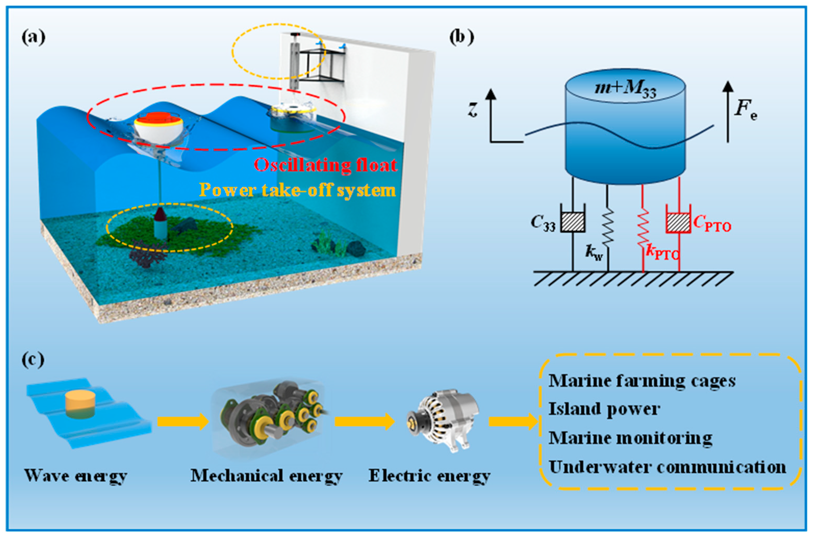
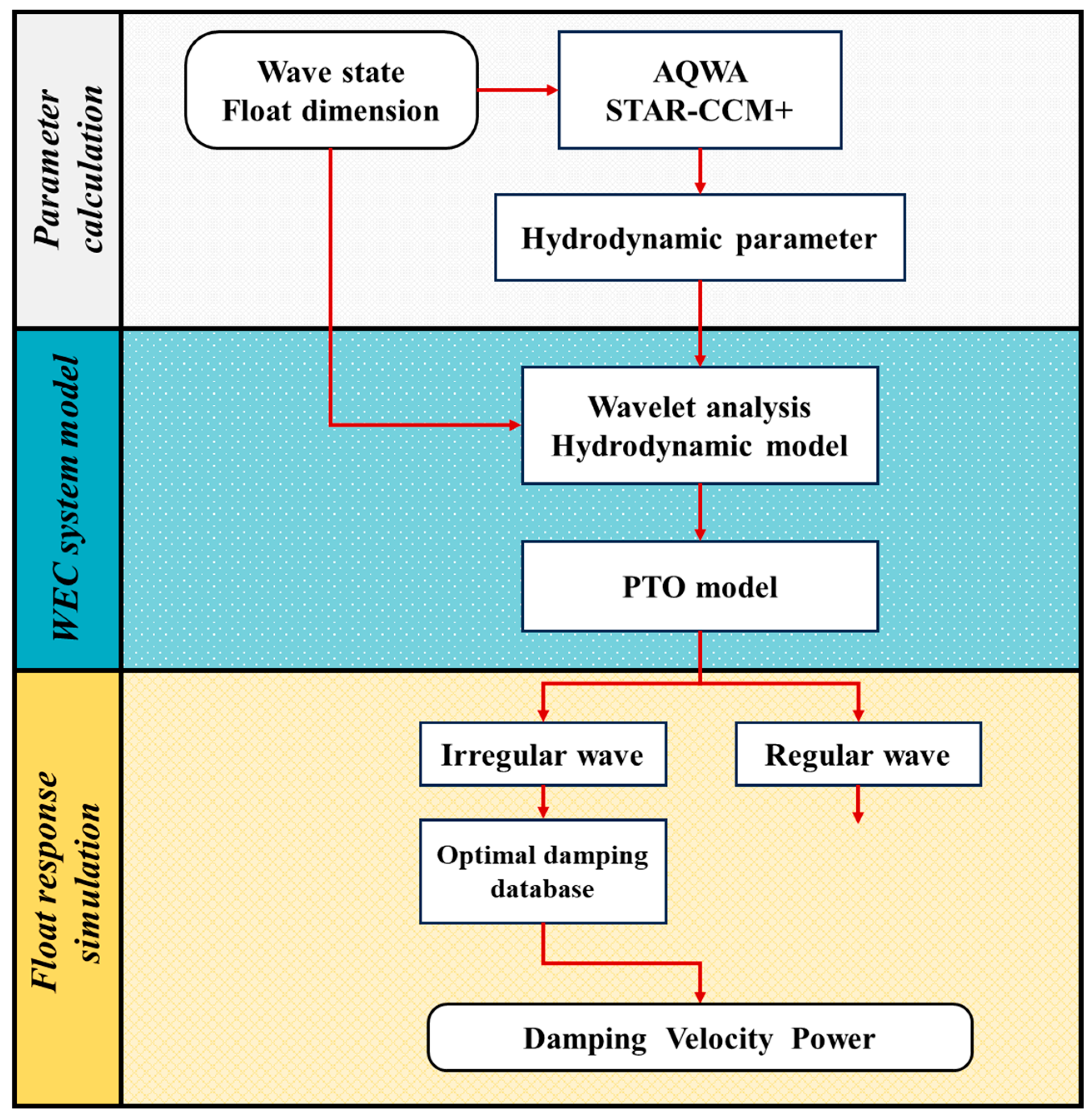
2. Modeling the Adaptive Damping PTO System

In this section, the motion equation of the float under regular wave conditions is derived in detail, laying a theoretical foundation for subsequent system modeling and analysis. Figure 2 clearly illustrates the modeling process of the adaptive variable-damping PTO (power take-off) system and highlights the core ideas and innovations of this study. Through numerical simulations and calculations under regular wave conditions, the motion responses of the float under various working conditions were obtained. Based on these results, an optimal damping database for the PTO system was established, providing key parameter support for efficient energy conversion under complex sea conditions.
To further enhance the system’s performance under irregular wave conditions, wavelet transform technology was employed to extract the frequency components of irregular waves, which were then used as input signals to the optimal damping database. In this way, the system can dynamically adjust its damping parameters in real time according to the actual sea conditions, thereby maximizing the absorption and conversion of wave energy. The optimal damping coefficients were calculated based on detailed analyses under regular wave conditions. Through extensive numerical experiments and optimization algorithms, optimal damping values under different wave frequencies and amplitudes were obtained and stored in the database. In practical applications, the database can quickly respond to changes in the frequency of irregular waves, providing accurate damping parameters for real-time system control, thereby significantly improving the efficiency of wave energy conversion.

2.1. Mathematical Model of the WEC

The model considers only the primary heave hydrodynamic response under wave conditions. The mathematical models for the float heave motion and the PTO system have been established in AMESIM.
The mathematical model adopts the assumption of linear wave theory. The fluid is incompressible, non-viscous, and the water depth is much greater than the wavelength. Figure 3 gives the Co-simulation analysis flow chart of WEC and the internal PTO system. The WEC model mainly includes the following forces: the wave excitation force Fe, the wave radiation force Fr, the wave hydrostatic force Fh, and the PTO system damping force FPTO.
According to Newton’s second law, the motion equation of a float in a wave can be formulated as follows:
m z ¨ = F r ( t ) + F s ( t ) + F e ( t ) + F PTO ( t )
where m is the mass of the float, and z is the heave motion of the float.
According to linear wave theory, Fr can be decomposed into the added mass force related to the float acceleration and the radiation damping force related to the velocity.
F r ( t ) = M 33 z ¨ + C 33 z ˙
The vertical wave excitation force Fe can be expressed as follows:
F e ( t ) = C e A sin ( ω t )
where Ce is the excitation force coefficient of the unit wave amplitude on the float; A is the amplitude ω is the wave frequency, and t is the time. The hydrostatic force Fs can be expressed as follows:
F s = k w z = ρ g π R 2 z
where kw is the hydrostatic stiffness; ρ is the density of sea water; πR2 is the waterline area of the cylindrical float. For simplified hydraulic systems, the load force FPTO can be expressed in terms of the load damping CPTO and stiffness kPTO:
F PTO = k PTO z + C PTO z ˙
Based on Equations (1) to (5), the above equations can be rearranged to obtain the float heave motion equation:
( m + M 33 ) z ¨ + C 33 z ˙ + k w z = F e ( t ) + F P T O ( t )
The power generated by the PTO system is related to the equivalent damping CPTO. The power generation is related to the equivalent damping coefficient of the electric generator and its rotational velocity, and the power generated by the PTO system can be written as follows:
P cap = C PTO z ˙ 2
The float heave motion model and PTO system model are established by combining Equation (6) with Equation (7) based on the AMESIM calculation model. Figure 4 shows the numerical simulation model of the oscillating float WEC and its PTO system, which can be used for regular wave and irregular calculations.
The construction of an appropriate damping database and WEC model design both depend on frequency domain analysis, which is a crucial stage in the WEC design process. It is necessary to perform frequency-domain analysis to obtain the corresponding hydrodynamic coefficients. The hydrodynamic coefficients are calculated by AQWA in this section, and the calculation simulation model has been verified. Figure 5 shows a grid of floats in AQWA with a height of 1 m, a draught of 0.5 m, and a diameter of 2 m.
According to the average sea state of the “National Shallow Sea prototype testing site (Weihai)”, the main hydrodynamic coefficients for the frequency range of ω = 0–5 rad/s are calculated in AQWA. The hydrodynamic coefficients M33, C33, and Ce are obtained as shown in Figure 6. The obtained hydrodynamic coefficients are stored as parameters to determine the float heave motion.
Using the wave conditions and hydrodynamic coefficients presented in Table 1, we calculated the wave motion response of the floats in the AMESIM model. The errors are defined as the discrepancies between the results obtained from AMESIM and those from the two software, AQWA (ANSYS 2022 R1) and STAR-CCM+ (2019). Figure 7 shows the heave displacement of the float changing over time, calculated by three solvers, AMESIM, AWQA, and STAR-CCM+. The maximum error between the time-domain AMESIM model and the AQWA is 1.01%, whereas the maximum error with STAR-CCM+ is 3.17%. The errors fall within an acceptable range, validating the utilization of the AMESIM model for subsequent power calculations and investigations into variable damping.

2.2. Establishing the Optimal Damping Database in Regular Waves

The mathematical model is developed for regular waves with frequency ω ranging from 0.5 to 4.0 rad/s and wave height H = 0.56 m, to calculate the capture power for several sea states. Figure 8 shows that the optimal damping coefficient for maximum power absorption of the float decreases as frequency increases within the 0–4 rad/s range. The red surface represents high capture power conditions, while the blue surface represents low capture power conditions. The maximum power absorption is diagonally distributed in the diagram, and gradually decreases to both sides.
To clearly show the optimization effect of an adaptive variable-damping PTO system, we compared power optimization and damping adjustment of the PTO system across various wave frequencies. The selected optimal damping coefficient of 15,000 N-(s/m) corresponds to the most common frequency of the Weihai sea state. The PTO system compares power absorption for optimization damping control (ODC), PODC, and a 15,000 N-(s/m) constant damping control (CDC) PCDC. Pc is used to indicate the percentage of power optimization. The damping adjustment ratio Dc is defined as equal to the damping variation coefficient of DODC compared to that of the DCDC:
P c = P ODC P CDC P CDC
D c = D ODC D CDC
Figure 9 shows the power optimization percentage Pc, and the damping adjustment ratio Dc in the wave state at wave height H = 0.56 m. Figure 9 shows Pc decreases as the wave frequency increases until it reaches the optimal damping frequency, after which it increases and then decreases again. Dc decreases initially until it reaches the natural frequency of the float, and then increases. As the frequency of the wave increases, Dc decreases with increasing frequency until it reaches the natural frequency of the float, after which it begins to increase. As the wave frequency continues to rise, Dc falls below 1 after 1.5 rad/s, which is consistent with the results shown in Figure 8. Pc and Dc reach the extreme point of the curve at 3.0 rad/s. This shows that when the RAO reaches its maximum, the heave response of the float also reaches its maximum, allowing more energy to be extracted from the wave with minimal damping. The values of Pc and Dc are directly related to the constant damping coefficient, and the power optimization coefficient Pc is always greater than 0, therefore, the optimization effect is always positive.
The optimal damping, which corresponds to the optimal power absorption, is situated within the diagonal region. The extracted optimal damping aligns with its corresponding power absorption. Figure 10 shows the optimal damping coefficient in the frequency domain and the corresponding optimal power absorption. The optimal damping coefficient first decreases and subsequently increases with increasing wave frequency. The optimal damping coefficient reaches a minimum in the resonant sea state (ω = 3.1 rad/s). The maximum power absorption first increases and then decreases with increasing wave frequency, and the change is relatively stable in the range of 1.5–3.2 rad/s, which is suitable for generating electricity.
The PTO optimal damping database of the wave frequency response is established, and the PTO system adjusts the damping of the PTO system according to the different wave frequencies of the WEC. The optimal damping database uses cubic spline interpolation to provide the corresponding optimal damping for the wave frequencies in the calculated interval. This facilitates the realization of an adaptive variable-damping function. Figure 11 shows the specific workflow of the adaptive variable-damping PTO system. First, the wave frequency is obtained by the WEC; then, the information is transmitted to the PTO optimal damping database to determine the optimal damping parameter, and the PTO system is adjusted to the optimal damping. Therefore, the wave frequency is resampled at every fixed time interval to readjust the PTO damping. Finally, the optimal variable-damping control of the PTO system is realized, and the power absorption of the wave energy generation device is optimized.

2.3. Irregular Wave Frequency Extraction Based on the Wavelet Transform

To extract the optimal damping from the PTO optimal damping database, the frequency of wave should be known in real time for irregular waves. The wavelet transform will be the solution, which compensates for the shortcomings of the Fourier transform. The frequency resolution and temporal resolution can be balanced according to the frequency, and the frequency response signal with time can be obtained.
To enhance the understanding of the application of the wavelet transform in this article, we provide a demonstration using an example of step frequencies. Figure 12 shows the workflow of applying the wavelet transform in this paper to extract the wave frequency.
This section sets the input signal to a combination of sinusoidal signals and provides the following expression:
z ( t ) = sin ( t )   0 <   t   60 sin ( 2 t )   60 <   t   120 sin ( 4 t )   120 <   t   180
In the wavelet transform, the selection of the mother wavelet function is highly important to the analysis results. In this paper, the Morlet wavelet is used to transform the wave data. The Morlet wavelet is a complex plane wave that has good locality in both the time domain and frequency domain. The expression is as follows:
ψ 0 ( t ) = π 1 / 4 exp ( t 2 2 ) exp ( i ω 0 t )
The input time series z(t) is subjected to the wavelet transform, and the wavelet transform result WT(τ, i) is expressed as follows:
W T ( τ , i ) = 1 i z ( t ) ψ ( t τ i ) d t
According to the wavelet transform result WT(τ,i), the wavelet energy spectrum PWT, i) is solved.
P W T τ , i = W T τ , i 2 i
The point (τmax, imax) of the wavelet energy spectrum PWT(τ, i) with the maximum energy scale at each time t is the wavelet ridge point. The connection of several wavelet ridge points is called the wavelet ridge line, and the frequency at the wavelet ridge line can be used as the instantaneous frequency of the signal. The wavelet energy spectrum curve is proposed, corresponding to the frequency coordinate, and the frequency time domain diagram of the wave curve is obtained. The accuracy of the wavelet transform is assessed by comparing the input wave frequency with the output wave frequency derived from the wavelet transform, thereby evaluating the discrepancies between the two. The average error in the wave frequency obtained by the wavelet change is 4.26% at 0–60 s, 2.87% at 60–120 s, and 1.85% at 120–180 s. The errors are within a reasonable range. In the subsequent calculation, the wavelet transform is used to extract the wave frequency history for irregular waves.

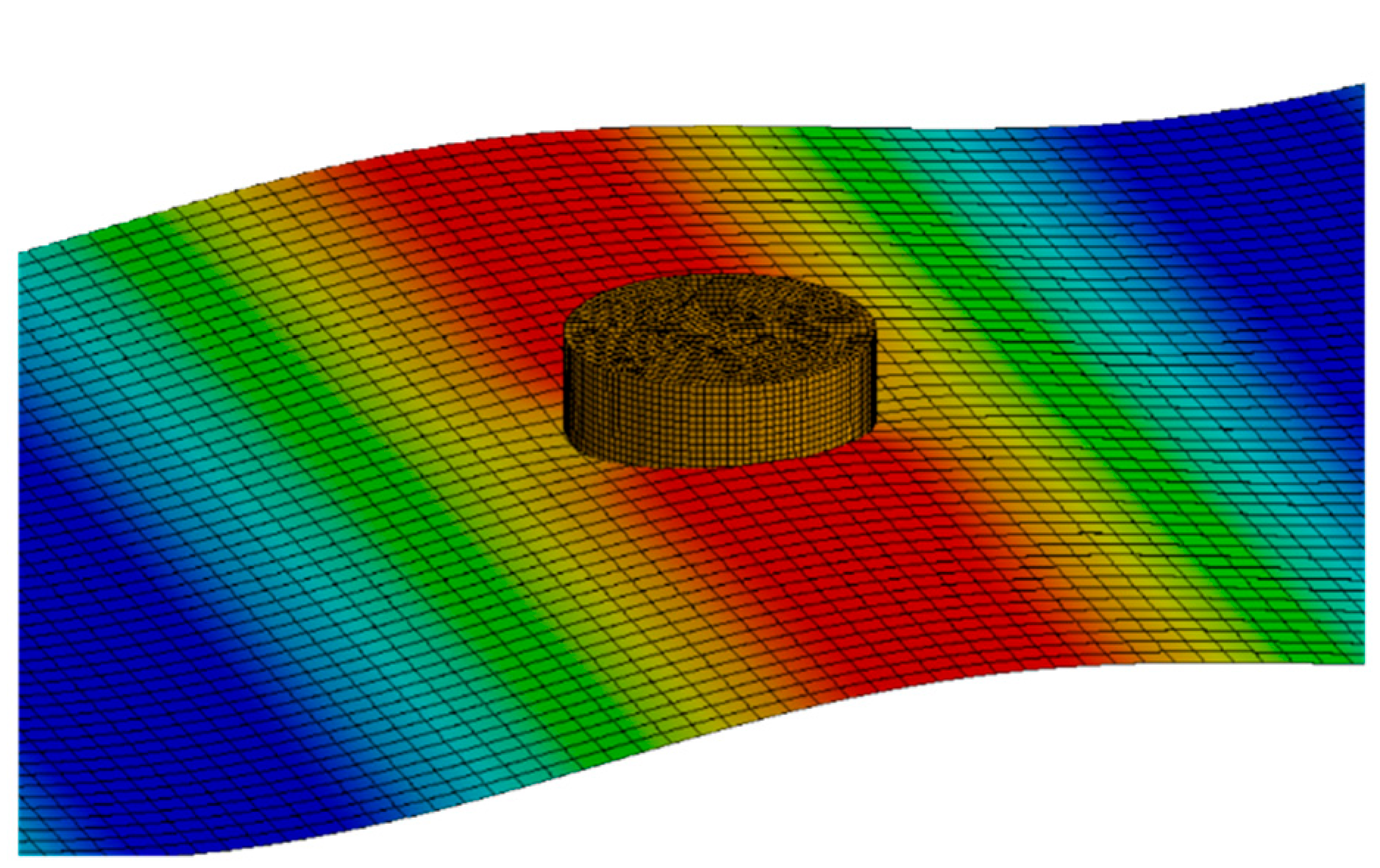
3. Validation of the Optimal Damping Database and Wavelet Transform

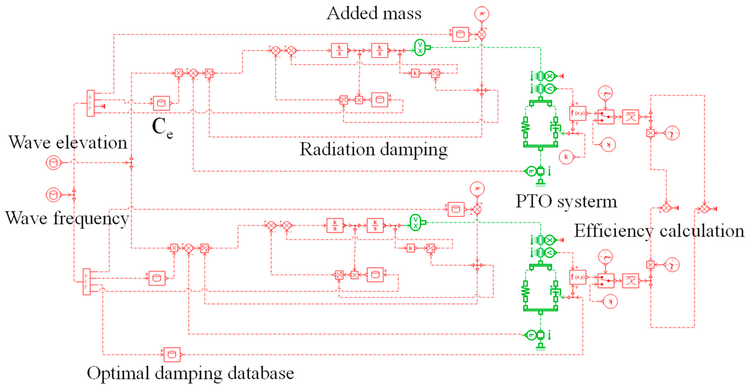
3.1. Co-Simulation to Verify the PTO Optimal Damping Database

The CFD method can be widely used to simulate the complex interaction between strongly nonlinear waves and floating bodies [33]. CFD is known to be a better choice for analyzing the hydrodynamic performance of a WEC under real sea conditions. In recent years, the commercial CFD solver STAR-CCM+ has become more popular in ocean engineering and can be used to simulate the motion of floats in waves. To verify the rationality of the PTO optimal damping database, the Co-simulation of STAR-CCM+ and AMESIM is used for verification. The hydrodynamic calculation of STAR-CCM+ is used to replace the float motion equation of AMESIM. Figure 13 shows the workflow of the Co-simulation model. The STAR-CCM+ numerical model can simulate the heave motion response of the float in waves well, and AMESIM can control the damping of the power absorption system.
Figure 14 shows the numerical model of float heave motion established in STAR-CCM +, in which the wave frequency is ω = 1.5 rad/s and H = 0.56 m. Numerical pool with velocity inlet on the left, pressure outlet on the right and slip walls on both sides.
The grid convergence has been performed in this section in three directions for wave simulation. Table 2 lists the three grid types, namely mesh A, mesh B, and mesh C. The time step and mesh size convergence of the model are verified.
Figure 15 shows the results of mesh size convergence verification. Three grid size meshes A, mesh B, and mesh C both have good performance in wave elevation. Considering the numerical calculation accuracy and calculation cost, mesh B is adopted in subsequent research. The time step of the above three mesh models is 0.01 s.
The time-step convergence with mesh B is verified, and the wave conditions remain unchanged. The wave heights at time steps t = T/836 (0.005 s), t = T/418 (0.01 s), and t = T/366 (0.015 s) are 0.352 m, 0.342 m, and 0.344 m, respectively. Figure 16 shows the time history curves for the time steps. The smaller the time step is, the closer the simulated wave is to the actual design value. Considering that the waves simulated by t = T/836 and t = T/418 are the same, but that the time cost increases significantly, in the subsequent simulation, the time step is t = T/418.
Figure 17 shows the heave response of the float when the damping coefficient is 15,000 N-s/m in AMESIM and Co-simulation. After the float stabilizes, the wave peak error of the heave response and the Co-simulation is 9.8%, and the period error is 0.5%. The error is caused by the AMESIM model not considering wave viscosity, which is in line with the expected error. The calculation results verify the reliability of the influence of the optimal damping database on the float heave response. Figure 18 verifies the relationship between the power absorption and the damping coefficient at 1.5 rad/s. When the sea state is determined, the power absorption first increases and subsequently decreases with increasing damping coefficient, and there is an optimal damping corresponding to the optimal power absorption. The power absorption value calculated via Co-simulation is smaller than that calculated via AMESIM due to the consideration of high-order waves and viscosity. For the same wave frequency, the optimal damping and power generation variations obtained are essentially the same, which verifies the reliability of the PTO optimal damping database. However, due to the large amount of calculations and the massive time cost of Co-simulation, more accurate optimal damping can be obtained via AMESIM calculations.

3.2. Verification of Wavelet Transform

The wavelet transform method mentioned earlier can be used to extract the frequency of irregular wave cases. To verify the accuracy of the wavelet transform extraction frequency, we used the AMESIM random function to construct the irregular wave module for calculation. Figure 19 shows the main mathematical model of the irregular wave module, which mainly involves setting the wave frequency and wave height through two random seeds.
Irregular waves are generated by setting random seeds of frequency and wave height, and the setting parameters are shown in Table 3. The frequency setting should meet the frequency range corresponding to the PTO optimal damping database, and the wave height setting should meet the transformation range of the local sea state.
Figure 20a shows the 1800 s irregular wave curve randomly generated by AMESIM, and the sampling time of the waves is 60 s. The verification process involves the application of the wavelet transform program to extract the wave frequency corresponding to the wave and compare it with the set frequency. Figure 20b shows the set frequency and the wave frequency extracted by the wavelet transform. The time series of the wave frequency obtained by the wavelet transform is compared with the wave frequency set by AMESIM. In the initial state, the wave extraction is unstable. The change is quick and positive after 60 s, with the wavelet transform-extracted wave frequency essentially matching the specified wave frequency. The average error between the wavelet transformation extraction frequency and the input frequency signal is 11.9%. The main cause of this inaccuracy is the decrease in the accuracy of the numerical calculations induced by various wave transitions. This error indicates that the wavelet transform program used in this study can accurately reflect the frequency of irregular waves.

4. Results of Different Waves Efficiency with the Wavelet Transform

4.1. Calculation of Combined Waves

The improved effect of the combined waves model constructed by the random signal in AMESIM on the optimal damping database is shown in Figure 21. Based on the hydrological data of the National Shallow Sea prototype testing site (Weihai), combined waves with a wave frequency of 0.5–4 rad/s and a wave amplitude of 0.05–0.4 m were constructed from random seeds. The PTO optimal damping database was established by the optimal damping coefficients of each frequency calculated in Chapter 2. A comparison is made between the power of two PTO systems, constant damping and optimal damping, using combined waves.
Figure 22a shows the frequency and amplitude changes in the range of 0–3600 s under random sea conditions. The random signal-generated curve fits the requirement for creating combined waves. To achieve short-term transformation of the simulated waves, we set the random variation in the wave frequency and height to 30 s. Figure 22b shows the combined waves under random signals and the corresponding float heave response. The heave motion 1 adopts the fixed damping strategy, and the optimal damping is 15,000 N-s/m under a damping coefficient of 1.5 rad/s. For heave motion 2, the optimal damping variable strategy is adopted. In the middle and high frequency regions, the heave motion of the float is larger for displacement 1 than for motion 2. This is because the constant damping is too large, which inhibits the movement of the float.
A heave response of 200 s at 2500–2700 s is extracted for local amplification analysis. Figure 23 shows the time history of the wave frequency and amplitude. Figure 24 shows the wave conditions and two heave responses under these conditions. Since the damping coefficient set by the control group is the optimal damping coefficient when the damping coefficient is 1.5 rad/s, 1.5 rad/s is an important reference value in the analysis. Moreover, the change in the optimal damping of the PTO system directly affects the heave displacement of the float. At 2500 s, the wave frequency is close to 1.5 rad/s, and the damping coefficient of PTO system 1 is close to that of PTO system 2, so the heave response is relatively close. When the wave frequency is greater than 1.5 rad/s, the optimal damping coefficient of PTO system 2 decreases, which increases the heave displacement of the float. When the wave frequency is less than 1.5 rad/s, the optimal damping coefficient of PTO system 2 increases, which suppresses the heave displacement of the float.
Figure 25 shows that the instantaneous captured power of the optimized variable-damping PTO is greater than that of the constant-damping PTO, and the magnification has a strong relationship with the amplitude and frequency of the wave. A PTO with improved variable-damping control may consistently output more power during different combined waves. There is a brief numerical instability at the time of wave frequency switching. This result has little effect on the calculation of average power and can still be applied. At different frequencies, the optimal damping can control the optimal speed response of the float to ensure that the generated power can be maximized.
Figure 26 depicts the variation in the optimal damping coefficient with the wave frequency response. The PTO’s optimal damping database allows for rapid adjustment of the PTO system damping corresponding to the changing wave frequencies. Figure 27 shows the improved power absorption results achieved through the adaptive variable-damping method. The optimization of the total power approximates a linear change. The average power absorption over 1 h is 245.04 W with constant damping control (CDC), while it increases to 398.24 W with optimal damping control (ODC). The WEC device with ODC can generate a total power absorption increase of 62.5% than the CDC. The results demonstrate that the optimal damping strategy of PTO can adjust the damping of the PTO system.

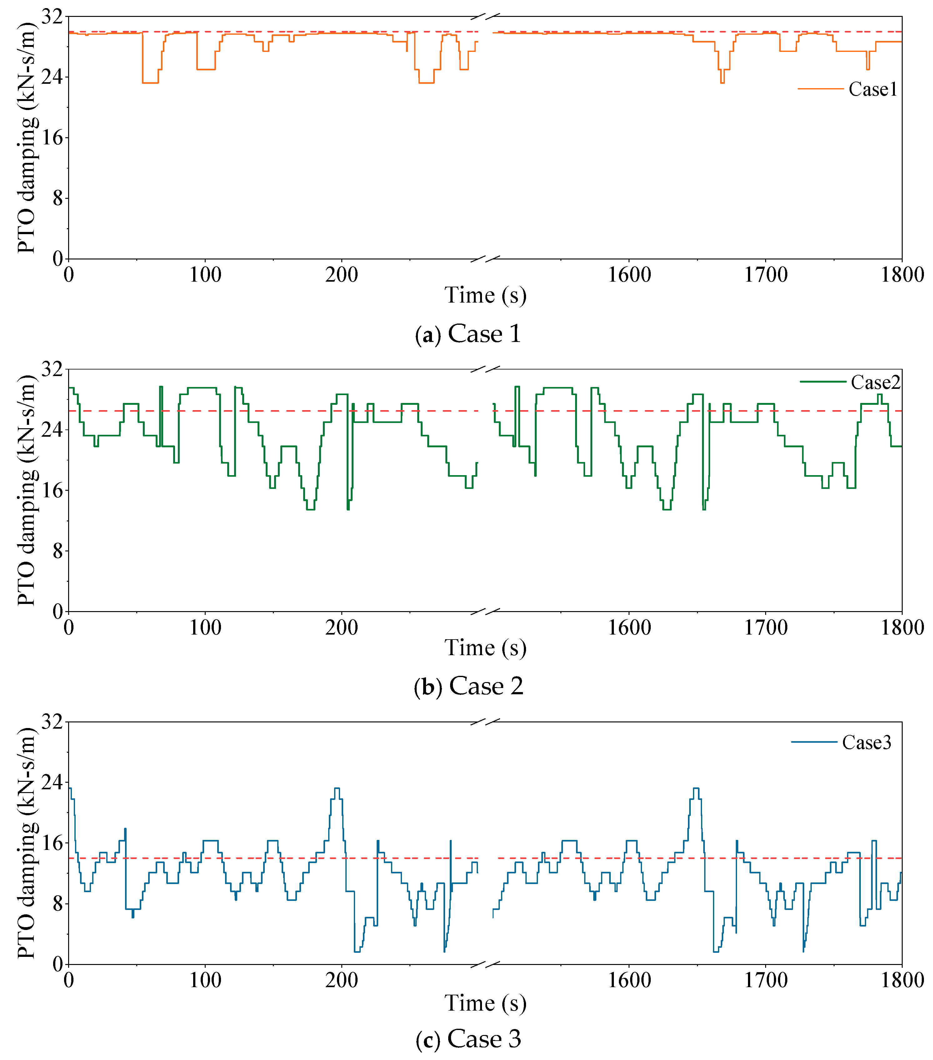
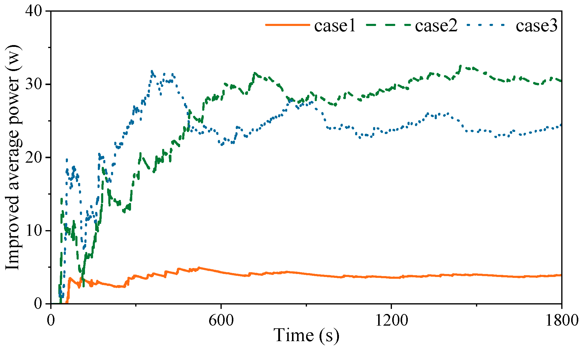
4.2. Calculation of Irregular Waves

The PTO system requires different damping adjustments due to the peak period and frequency range of irregular waves, resulting in varying degrees of power optimization. Therefore, investigating the impact of multiple irregular waves on the performance of an adaptive variable-damping PTO system holds practical engineering significance [35,36]. We further discuss the optimization of power absorption by the adaptive variable-damping PTO system in response to irregular waves, with the irregular waves computed using STAR-CCM+ software for a simulation time of 1800 s.
The STAR-CCM+ software produces three different irregular waves with varying significant wave heights and effective periods based on the JONSWAP spectrum. These waves are divided into three cases to study the performance of the adaptive variable-damping PTO system. The three irregular wave curves with different dominant frequencies are characterized primarily by their effective periods and wavelengths (Table 4).
Figure 28 shows the calculated wave elevation of Cases 1–3, which reveals a high degree of irregularity. Under actual sea conditions, the speed of wave transformation is more stable than that of STAR-CCM + irregular wave transformation. Therefore, the wave is used to calculate the optimal damping database of the PTO system, which can better ensure that it can be applied under actual sea conditions.
Figure 29 presents the spectra of three irregular waves after Fourier transformation and smoothing. A comparison between the estimated spectra and theoretical spectra indicates a good fit, thereby demonstrating that the selected irregular waves meet the requisite criteria for wave generation.
The irregular waves are numerically processed to generate frequency–time-domain information that can be used in the PTO optimal damping database. Through wavelet transform, three kinds of irregular waves generate the wavelet energy spectrum as shown in Figure 30. The wavelet energy spectrum shows the area with high energy in the irregular wave, which can intuitively reflect the change in wave energy.
The highest point of the wavelet energy spectrum of the three irregular wave curves is extracted as the main frequency of the wave at the corresponding time. Figure 31 shows the frequency variation in Cases 1–3, and the frequency distribution of each case is mainly by the setting parameters.
The wave elevation and its corresponding frequency are set as input signals for the AMESIM adaptive variable-damping PTO system model for calculation. Figure 32 shows the time history of the damping of the adaptive variable-damping PTO system model. Moreover, under the action of variable damping, the velocity of the float also changes accordingly, as shown in Figure 33.
To intuitively obtain the optimization effect of the adaptive variable-damping PTO system, the average improved power can be calculated using Formula (14), and the optimization effect under irregular wave conditions can be performed:
P IMP = P ODC P CDC
Figure 34 shows the optimization effect of the average power absorption within 1800 s. Case 1 increased the average power by 4.00 W, Case 2 increased the average power by 30.46 W, and Case 3 increased the average power by 24.64 W. Under the two PTO systems in irregular waves, the adaptive variable-damping PTO system absorbed more wave energy than the constant-damping PTO system. The increase in the power absorption is not the same under different wave conditions, and the energy contained in irregular waves is different. Additionally, the accuracy of the wavelet transform is a crucial factor that affects the optimal power of an adaptive variable-damping PTO system.

5. Discussion

This research developed a mathematical model for an adaptive PTO system and investigated power absorption and heave response. The optimal PTO damping database under different wave frequencies is calculated by the model, and the viscous waves are verified by Co-simulation. The wavelet transform is used to extract the wave frequency of irregular waves timely manner, enhancing the power absorption of the PTO system. The influence of adaptive variable PTO damping with optimal damping control (ODC) on the power absorption performance is calculated for irregular waves. The following conclusions can be drawn from this study:
(1)
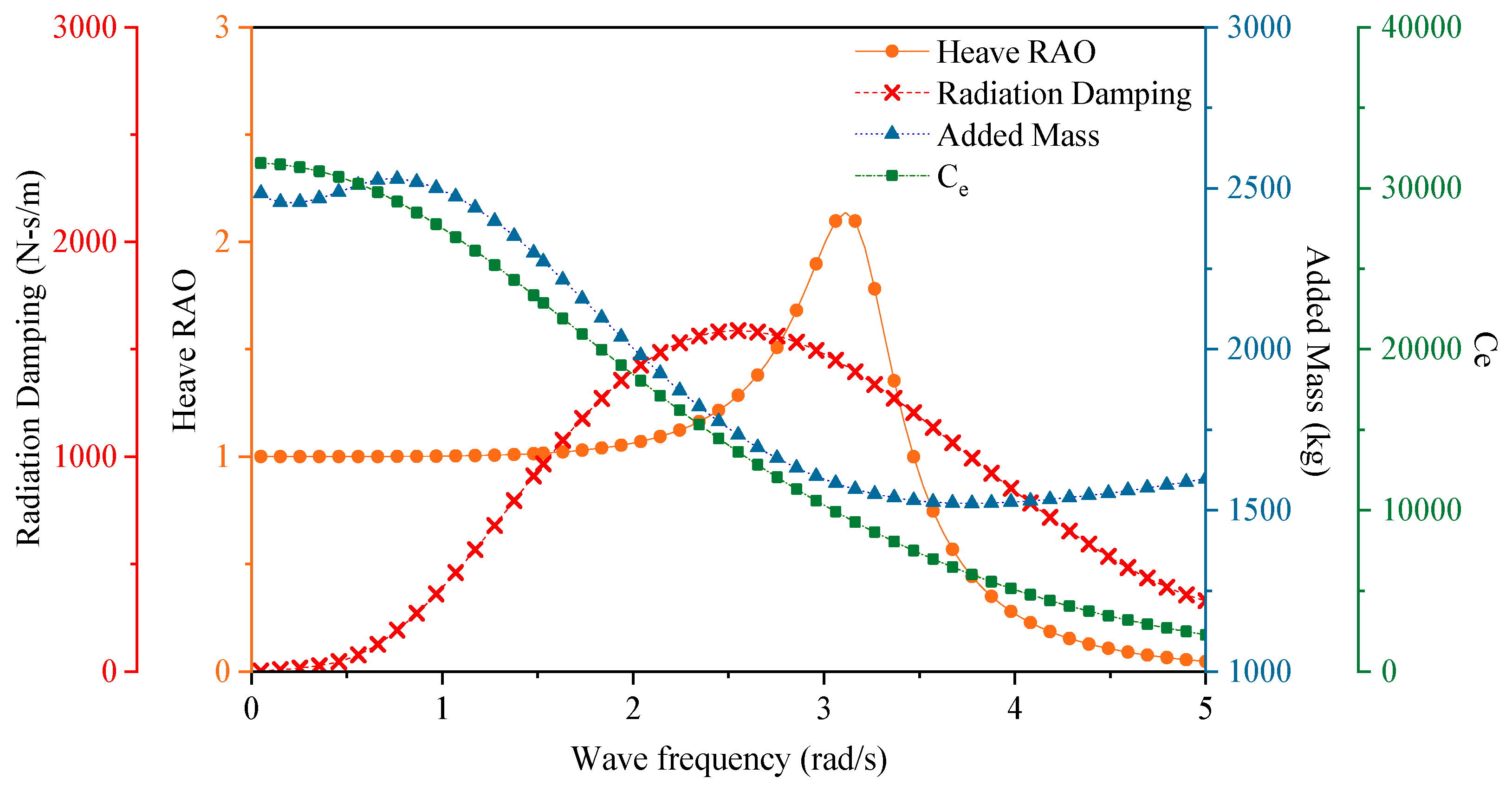
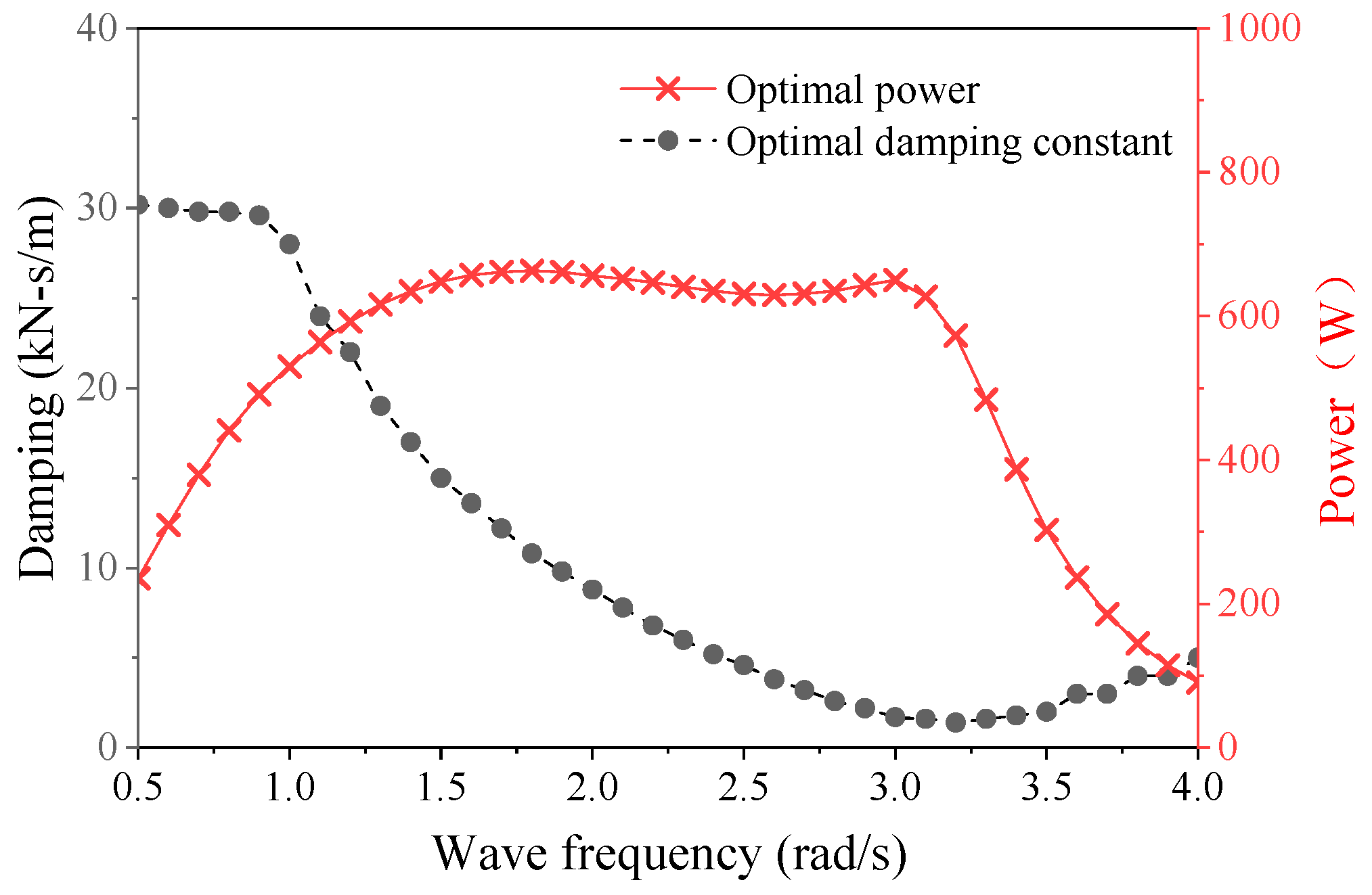
The effect of the optimal PTO damping for different wave frequencies is analyzed. ω = 1.5–3.0 rad/s is the better working sea state, because it captures more wave energy in a limited wave frequency range and specific optimal PTO damping. The obtained wave energy is relatively stable and provides good protection for the power absorption device, despite the larger range of PTO damping.
(2)
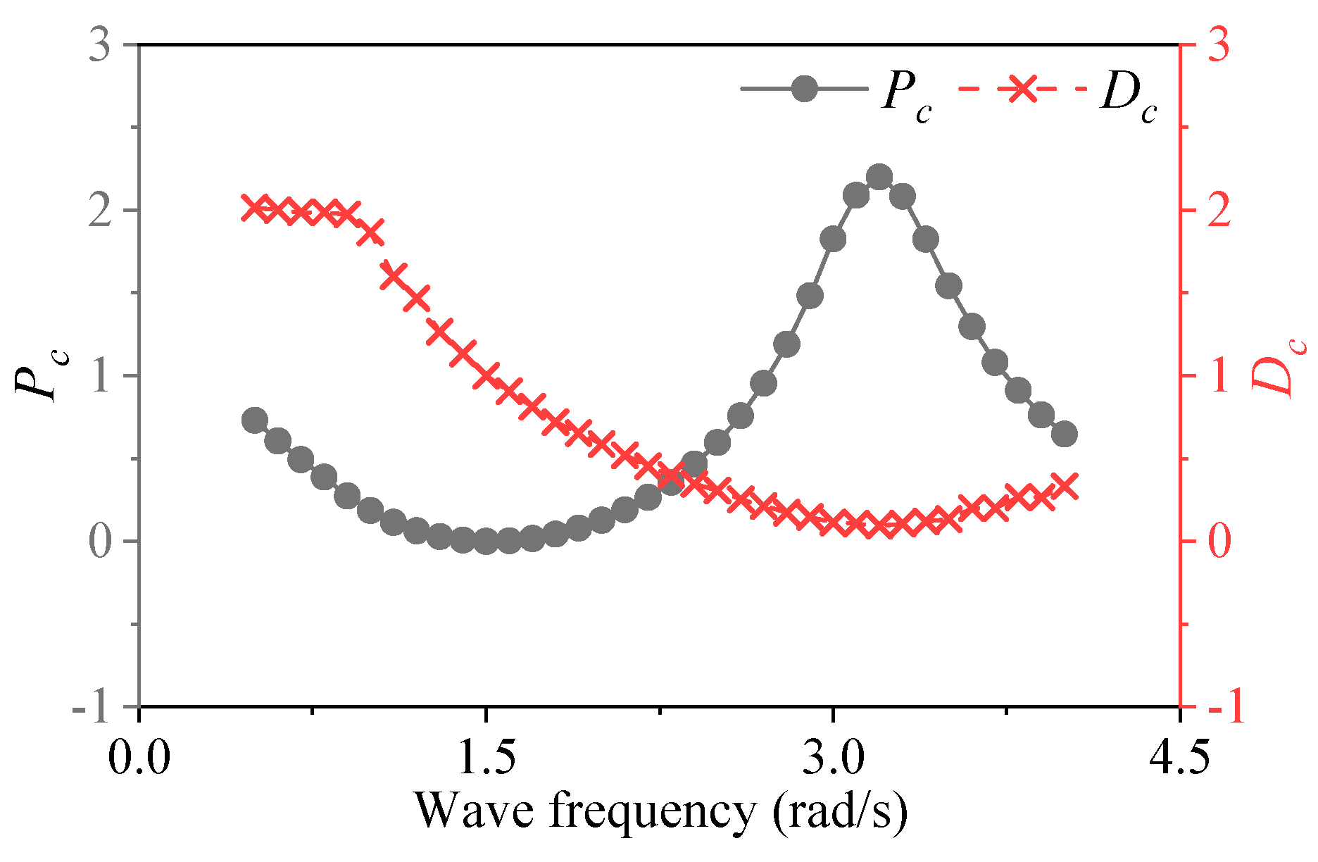
The use of dimensionless numbers Pc and Dc shows that the result of power optimization is positive optimization. When the wave frequency is close to the WECs intrinsic frequency, Dc reaches the minimum value, and the Pc is most obvious.
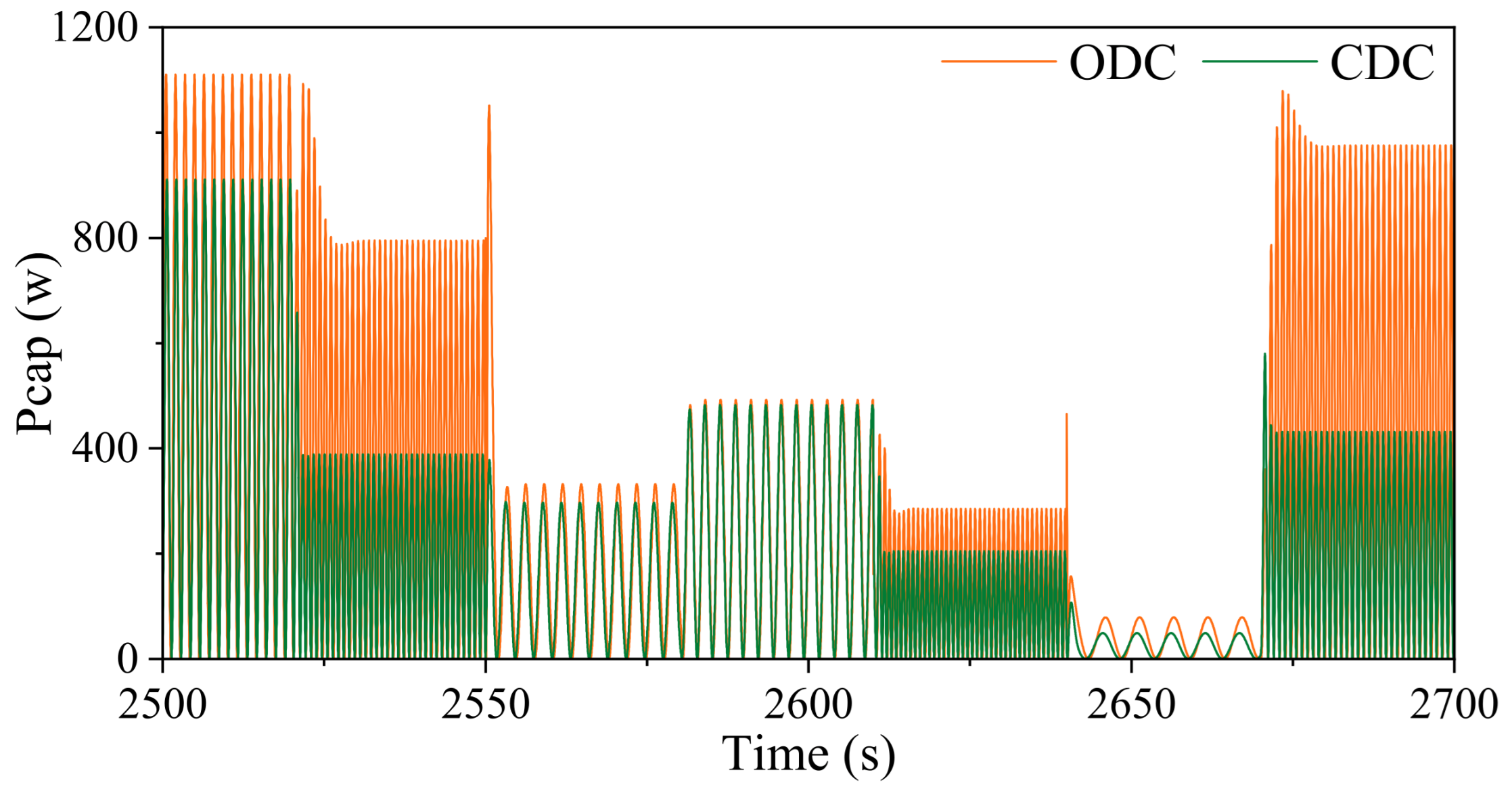
(3)
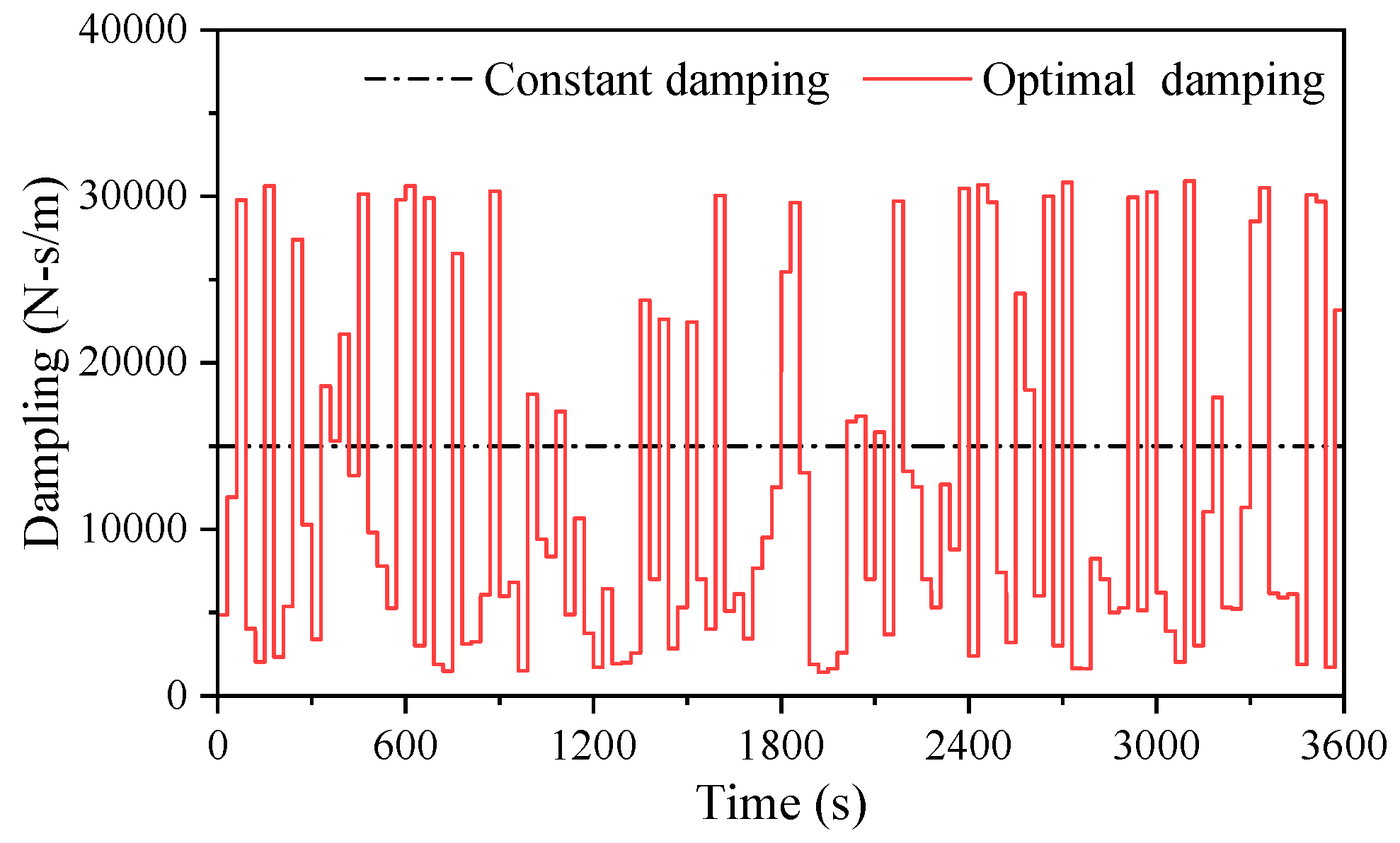
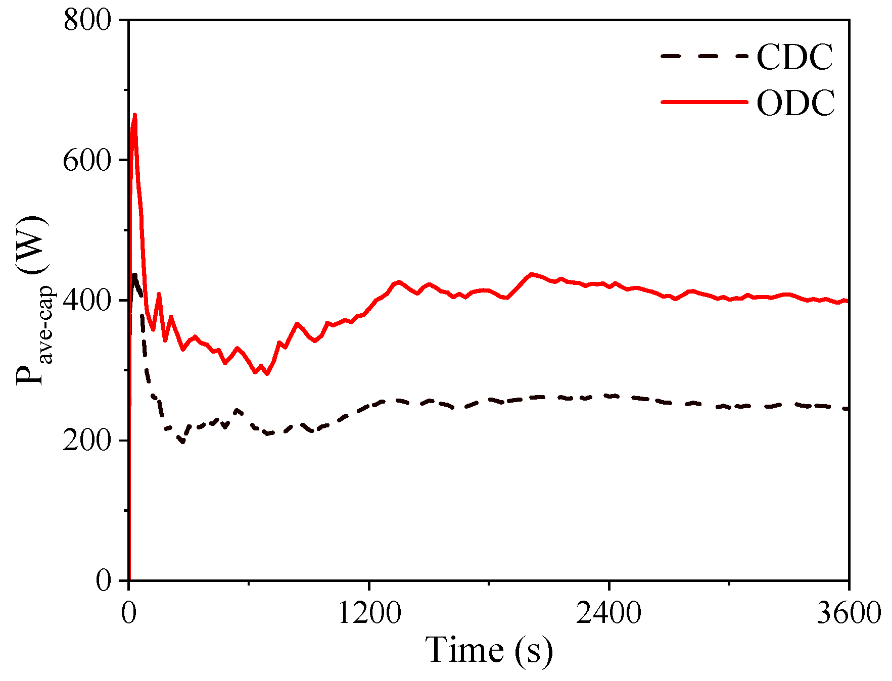
The effects of constant damping control (CDC) PTO and ODC PTO on AMESIM were compared. The optimization effect increases in average power absorption for 1 h, is approximately 0.15 kWh, and the total increase in power absorption is 62.5%. It has a good improvement effect in the relatively slow-changing wave environment.
(4)
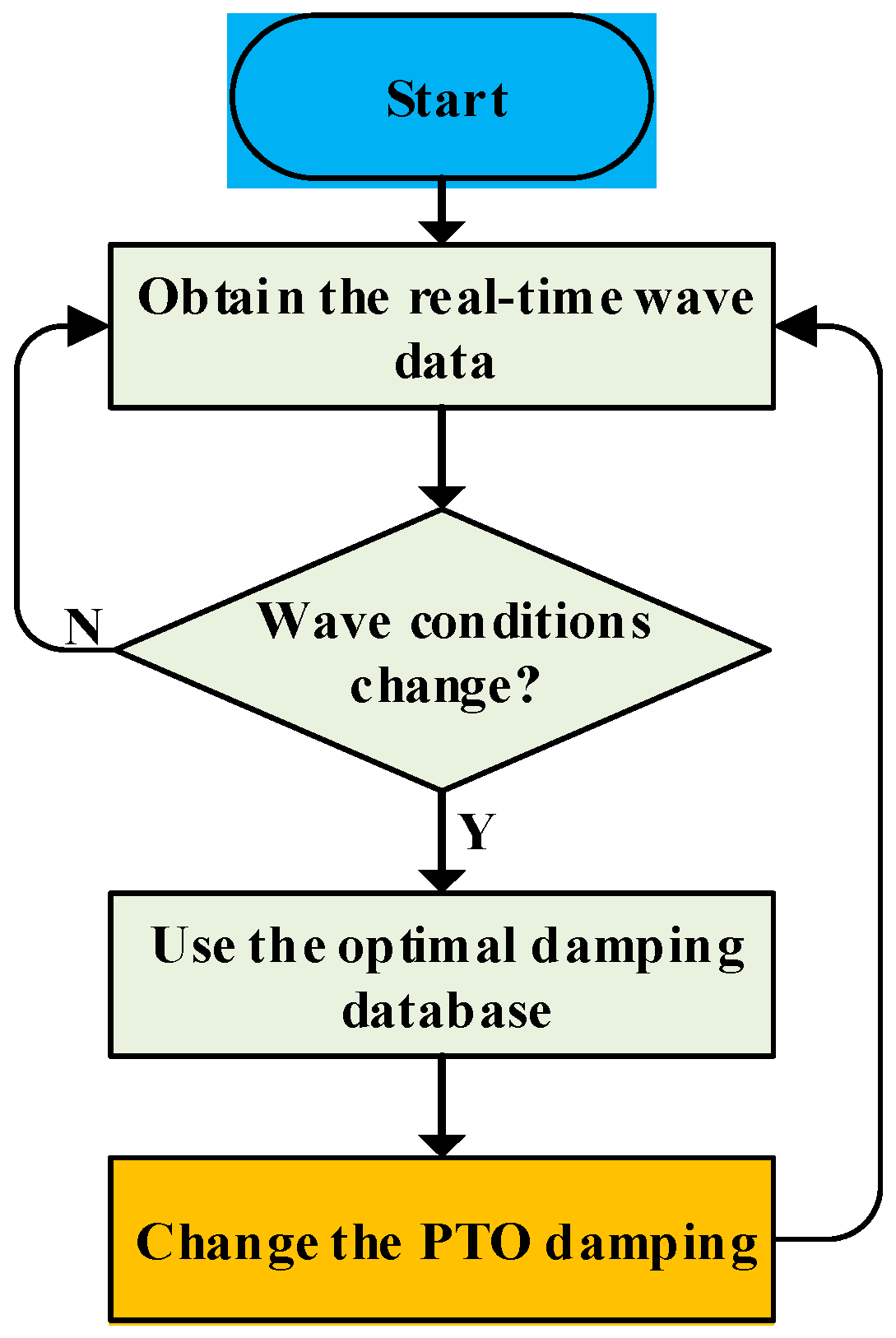
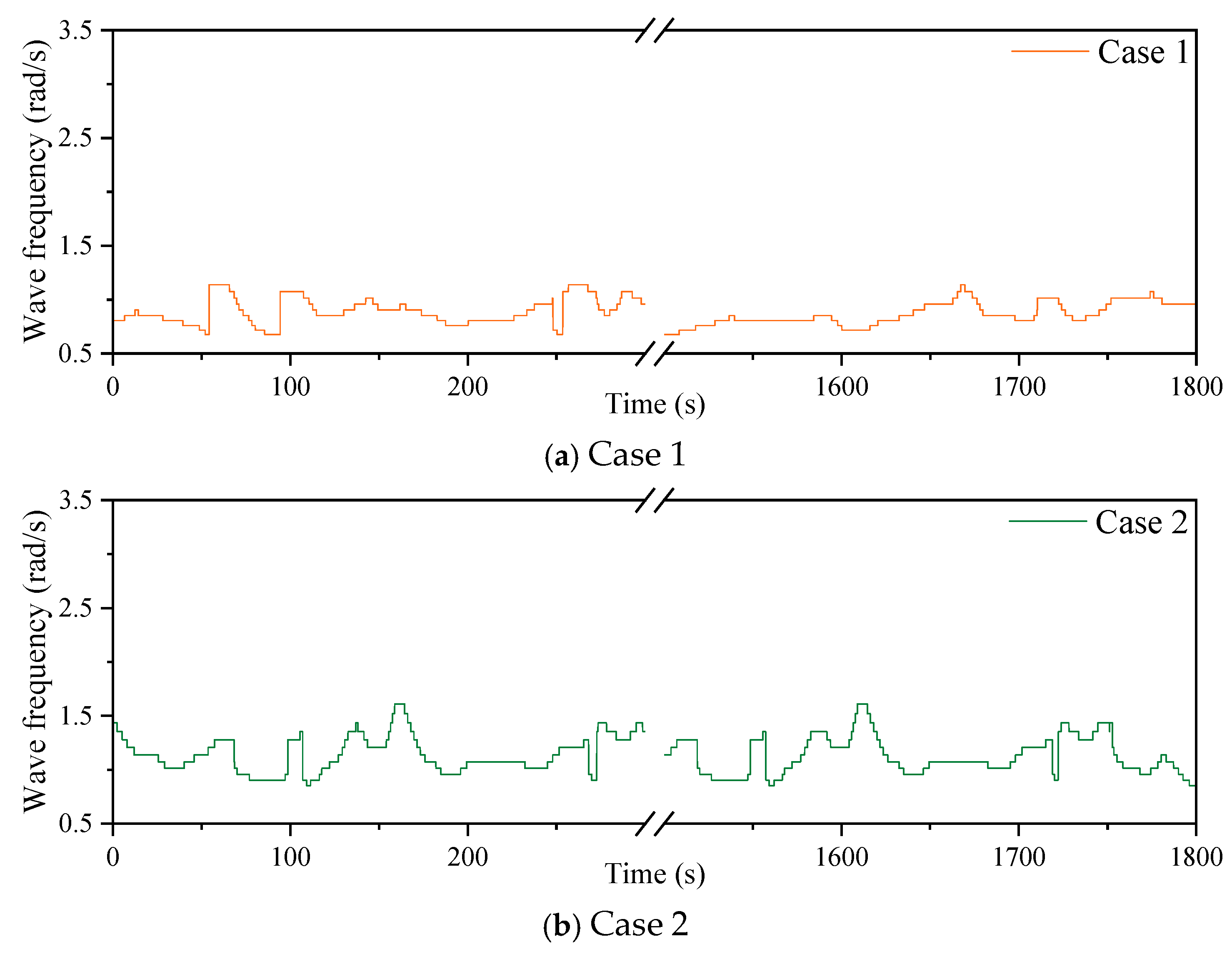
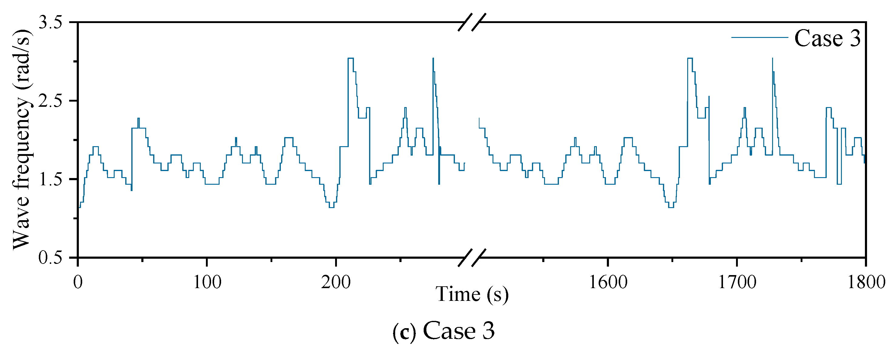
The results of the PIMP algorithm are all positive, and they are not the same for the three spectral peak periods. The wave height recorder can be used to obtain the frequency in real time to achieve better optimization results under actual sea conditions.
In practical applications, the wave frequency change rate in real waves is typically smaller than the frequency variation in numerical simulations of irregular waves. The adaptive variable-damping PTO system demonstrates high reliability, rapid response speed, and holds significant practical value. This study offers a solution to address the challenges of unstable power absorption and low wave capture efficiency encountered by oscillating float WECs in real wave conditions.

Author Contributions

Conceptualization, G.H. and R.H.; methodology, R.H. and P.J.; original draft, R.H. and G.H.; software, Z.L. and R.H.; writing—review and editing, G.H. and C.L. All authors have read and agreed to the published version of the manuscript.

Funding

This research was funded by the National Natural Science Foundation of China (52471326), National Key Research and Development Program (2023YFB4204200), State Key Laboratory of Offshore Wind Power Equipment and Wind Energy High-Efficient Utilization, the Shandong Provincial Natural Science Foundation (ZR2024QE096), and SKL - OWPE & WEHEU under Grants HFQZS2024-15.

Data Availability Statement

Data are contained within the article.

Conflicts of Interest

The authors declare no conflicts of interest.

Nomenclature

AWave amplitudeFrThe added mass and radiation damping force
M33Added massFsThe hydrostatic force
C33Radiation dampingFeVertical wave excitation force
mMass of floatFPTOPTO force
CeExcitation force coefficientPcapGenerated power
kwHydrostatic stiffness of floatHWave height
RThe radius of the floatPcPercentage of power optimization.
ρThe density of sea waterDcDamping adjustment ratio
ωwave frequencyttime
CPTOLoad damping of PTOPWT(τ,i)Wavelet energy spectrum
kPTOStiffness of PTOWT(τ,i)Wavelet transform result

References

  1. Yolcan, O.O. World energy outlook and state of renewable energy: 10-Year evaluation. Innov. Green Dev. 2023, 2, 100070. [Google Scholar] [CrossRef]
  2. He, G.; Zhao, C.; Liu, C.; He, R.; Luan, Z. Power absorption and dynamic response analysis of a hybrid system with a semi-submersible wind turbine and a Salter’s duck wave energy converter array. Energy 2024, 305, 132210. [Google Scholar] [CrossRef]
  3. Gaspar, J.F.; Pinheiro, R.F.; Mendes, M.J.C.; Kamarlouei, M.; Soares, C.G. Review on hardware-in-the-loop simulation of wave energy converters and power take-offs. Renew. Sustain. Energy Rev. 2024, 191, 114144. [Google Scholar] [CrossRef]
  4. Khojasteh, D.; Shamsipour, A.; Huang, L.; Tavakoli, S.; Haghani, M.; Flocard, F.; Farzadkhoo, M.; Iglesias, G.; Hemer, M.; Lewis, M.; et al. A large-scale review of wave and tidal energy research over the last 20 years. Ocean Eng. 2023, 282, 114995. [Google Scholar] [CrossRef]
  5. Barua, A.; Rasel, S. Advances and challenges in ocean wave energy harvesting. Sustain. Energy Technol. Assess. 2024, 61, 103599. [Google Scholar] [CrossRef]
  6. Gallutia, D.; Fard, M.T.; Soto, M.G.; He, J. Recent advances in wave energy conversion systems: From wave theory to devices and control strategies. Ocean. Eng. 2022, 252, 111105. [Google Scholar] [CrossRef]
  7. Ahamed, R.; McKee, K.; Howard, I. Advancements of wave energy converters based on power take off (PTO) Systems: A review. Ocean Eng. 2020, 204, 107248. [Google Scholar] [CrossRef]
  8. Ghaedi, A.; Sedaghati, R.; Mahmoudian, M.; Bazyari, S. Reliability modeling of wave energy converters based on pelamis technology. Electr. Power Syst. Res. 2024, 227, 109977. [Google Scholar] [CrossRef]
  9. Yang, B.; Duan, J.; Chen, Y.; Wu, S.; Li, M.; Cao, P.; Jiang, L. A critical survey of power take-off systems based wave energy converters: Summaries. Ocean Eng. 2024, 298, 117149. [Google Scholar] [CrossRef]
  10. Xi, Y.; Wang, J.; Zi, Y.; Li, X.; Han, C.; Cao, X.; Hu, C.; Wang, Z. High efficient harvesting of underwater ultrasonic wave energy by triboelectric nanogenerator. Nano Energy 2017, 38, 101–108. [Google Scholar] [CrossRef]
  11. He, G.; Luan, Z.; Zhang, W.; He, R.; Liu, C.; Yang, K.; Yang, C.; Jing, P.; Zhang, Z. Review on research approaches for multi-point absorber Wave energy converters. Renew. Energy 2023, 218, 119237. [Google Scholar] [CrossRef]
  12. Gao, H.; He, K.; Guo, W.; Gao, X.; Li, B.; Zou, J.; Ding, S.; Song, Y. Response power of floating three-body wave energy converter with different shapes. Sustain. Energy Technol. Assess. 2023, 57, 103225. [Google Scholar] [CrossRef]
  13. He, G.; Liu, C.; Zhang, W.; Luan, Z.; Zhang, Z. Numerical study of the effect of central platform motion on the wave energy converter array. Ocean Eng. 2023, 286, 115483. [Google Scholar] [CrossRef]
  14. Amini, E.; Mehdipour, H.; Faraggiana, E.; Golbaz, D.; Mozaffari, S.; Bracco, G.; Neshat, M. Optimization of hydraulic power take-off system settings for point absorber wave energy converter. Renew. Energy 2022, 194, 938–954. [Google Scholar] [CrossRef]
  15. Çelik, A. An experimental investigation into the effects of front wall geometry on OWC performance for various levels of applied power take off dampings. Ocean. Eng. 2022, 248, 110761. [Google Scholar] [CrossRef]
  16. Zhang, W.; Zhou, Y.H.; Zhou, X.G. Power take-off mechanism analysis of oscillating-buoy wave energy converter. J. Vib. Shock. 2020, 39, 38–44. [Google Scholar]
  17. He, G.; Liu, C.; Chen, B.; Ghassemi, H.; Liu, L.; Yang, K.; Luan, Z. Effect of piecewise damping torques and coefficients on power absorption of a point-absorber wave energy converter. Renew. Energy 2023, 219, 119440. [Google Scholar] [CrossRef]
  18. Gadelho, J.; Rezanejad, K.; Soares, C.G.; Santos, J.; Anastas, G.; Fortes, C. Experimental study of an onshore dual chamber oscillating water column device. Ocean Eng. 2024, 300, 117240. [Google Scholar] [CrossRef]
  19. Khatri, P.; Liu, Z.; Rudolph, J.; Wang, X. A study of a modified design of dumbbell-shaped flux switching tubular linear generator for regular wave energy conversion. Renew. Energy 2023, 208, 287–300. [Google Scholar] [CrossRef]
  20. Xu, J.; Yang, Y.; Hu, Y.; Xu, T.; Zhan, Y. MPPT Control of Hydraulic Power Take-Off for Wave Energy Converter on Artificial Breakwater. J. Mar. Sci. Eng. 2020, 8, 304. [Google Scholar] [CrossRef]
  21. Ghafari, H.R.; Ghassemi, H.; Neisi, A. Power matrix and dynamic response of the hybrid Wavestar-DeepCwind platform under different diameters and regular wave conditions. Ocean Eng. 2022, 247, 110734. [Google Scholar] [CrossRef]
  22. Harms, J.; Hollm, M.; Dostal, L.; Kern, T.A.; Seifried, R. Design and optimization of a wave energy converter for drifting sensor platforms in realistic ocean waves. Appl. Energy 2022, 321, 119303. [Google Scholar] [CrossRef]
  23. Liu, Y.; Cho, Y.-H.; Mizutani, N.; Nakamura, T. Simplified BEM-based mathematical model for bottom-hinged oscillating wave surge con-verters under large-amplitude regular waves. Ocean Eng. 2023, 272, 113893. [Google Scholar] [CrossRef]
  24. Grasberger, J.; Yang, L.; Bacelli, G.; Zuo, L. Control co-design and optimization of oscillating-surge wave energy converter. Renew. Energy 2024, 225, 120234. [Google Scholar] [CrossRef]
  25. Liang, H.; Qiao, D.; Wang, X.; Zhi, G.; Yan, J.; Ning, D.; Ou, J. Energy capture optimization of heave oscillating buoy wave energy converter based on model predictive control. Ocean Eng. 2023, 268, 113402. [Google Scholar] [CrossRef]
  26. Dong, F.; Pan, S.; Gong, J.; Cai, Y. Maximum power point tracking control strategy based on frequency and amplitude control for the wave energy conversion system. Renew. Energy 2023, 215, 118973. [Google Scholar] [CrossRef]
  27. Zhang, Y.; Zhao, Y.; Sun, W.; Li, J. Ocean wave energy converters: Technical principle. Renew. Sustain. Energy Rev. 2021, 141, 110764. [Google Scholar] [CrossRef]
  28. Zang, Z.; Zhang, Q.; Qi, Y.; Fu, X. Hydrodynamic responses and efficiency analyses of a heaving-buoy wave energy converter with PTO damping in regular and irregular waves. Renew. Energy 2018, 116, 527–542. [Google Scholar] [CrossRef]
  29. Liu, J.; Li, X.; Yang, L.; Wu, X.; Huang, J.; Mi, J.; Zuo, L. Achieving optimum power extraction of wave energy converters through tunable mechanical com-ponents. Energy 2024, 291, 130322. [Google Scholar] [CrossRef]
  30. Peng, W.; Zhang, Y.; Zou, Q.; Zhang, J.; Li, H. Effect of varying PTO on a triple floater wave energy converter-breakwater hybrid system: An experimental study. Renew. Energy 2024, 224, 120100. [Google Scholar] [CrossRef]
  31. Li, Y.; Zhang, X.; Xiao, L. Parametric study on power capture performance of an adaptive bistable point absorber wave energy converter in irregular waves. J. Ocean Eng. Sci. 2022, 7, 383–398. [Google Scholar] [CrossRef]
  32. Ni, W.; Zhang, X.; Zhang, W.; Liang, S. Numerical investigation of adaptive damping control for raft-type wave energy converters. Renew. Energy 2021, 175, 520–531. [Google Scholar] [CrossRef]
  33. Ali, R.; Meek, M.; Robertson, B. Submerged wave energy converter dynamics and the impact of PTO-mooring configuration on power performance. Renew. Energy 2025, 243, 122525. [Google Scholar] [CrossRef]
  34. Vakili, A.; Pourzangbar, A.; Ettefagh, M.M.; Haghghi, M.A. Optimal control strategy for enhancing energy efficiency of Pelamis wave energy converter: A Simulink-based simulation approach. Renew. Energy Focus 2025, 53, 100685. [Google Scholar] [CrossRef]
  35. Pourzangbar, A.; Vaezi, M. Optimal design of brace-viscous damper and pendulum tuned mass damper using Particle Swarm Optimization. Appl. Ocean Res. 2021, 112, 102706. [Google Scholar] [CrossRef]
  36. Pourzangbar, A.; Vaezi, M. Effects of pendulum tuned mass dampers on the dynamic response of jacket platforms. Ocean Eng. 2022, 249, 110895. [Google Scholar] [CrossRef]
Figure 1. Concept design of a WEC, (a) structural diagram of an oscillating float WEC, (b) dynamic model of float in waves, and (c) energy conversion and utilization.
Energies 18 03328 g001
Figure 2. Flow chart of WEC with adaptive PTO system in irregular wave.
Energies 18 03328 g002
Figure 3. Force analysis of the WEC.
Energies 18 03328 g003
Figure 4. Numerical simulation model of the WEC and PTO system in AMESIM.
Energies 18 03328 g004
Figure 5. The mesh of the wave float.
Energies 18 03328 g005
Figure 6. RAO, the wave excitation force coefficient, the added mass, and the radiation damping coefficient of the float.
Energies 18 03328 g006
Figure 7. Heave displacement in AMESIM, AQWA, and STAR-CCM +.
Energies 18 03328 g007
Figure 8. Schematic diagram of the power absorption.
Energies 18 03328 g008
Figure 9. Power relative gain ratio Pc and damping change factor Dc in wave states with H = 0.56 m.
Energies 18 03328 g009
Figure 10. Optimal damping coefficients and maximum power absorption.
Energies 18 03328 g010
Figure 11. Flow chart of the PTO optimal damping database.
Energies 18 03328 g011
Figure 12. The schematic of the extraction of the wavelet ridge for the signal.
Energies 18 03328 g012
Figure 13. Co-simulations in AMESIM and STAR-CCM+.
Energies 18 03328 g013
Figure 14. Numerical model of float heaving motion in STAR-CCM+.
Energies 18 03328 g014
Figure 15. Different mesh sizes model convergence.
Energies 18 03328 g015
Figure 16. Different time steps model convergence.
Energies 18 03328 g016
Figure 17. Displacement comparison.
Energies 18 03328 g017
Figure 18. Power absorption (ω = 1.5 rad/s).
Energies 18 03328 g018
Figure 19. Computational model of a float with an irregular wave in AMESIM.
Energies 18 03328 g019
Figure 20. (a). Irregular wave in AMESIM (b). Comparisons of the wavelet frequency with the input frequency signal.
Energies 18 03328 g020
Figure 21. Combined waves power calculation model.
Energies 18 03328 g021
Figure 22. Irregular wave signal and heave motion. (a) Combined waves input signal and frequency. (b) Wave surface lift and heave displacement of combined waves.
Energies 18 03328 g022
Figure 23. Input signal in AMESIM.
Energies 18 03328 g023
Figure 24. Heave motion of two types of PTOs in AMESIM.
Energies 18 03328 g024
Figure 25. PTO instantaneous captured power.
Energies 18 03328 g025
Figure 26. Damping with wave frequency.
Energies 18 03328 g026
Figure 27. Average power improvement in 1 h.
Energies 18 03328 g027
Figure 28. Three irregular waves in the STAR-CCM+.
Energies 18 03328 g028
Figure 29. Spectrum validation of three irregular waves.
Energies 18 03328 g029
Figure 30. Three irregular wave wavelet ridges in STAR-CCM+.
Energies 18 03328 g030
Figure 31. Three irregular wavelet frequencies in STAR-CCM+.
Energies 18 03328 g031aEnergies 18 03328 g031b
Figure 32. Three cases of PTO damping in an irregular wave.
Energies 18 03328 g032
Figure 33. Three float velocities in irregular waves.
Energies 18 03328 g033
Figure 34. Three case average power of the PTO system in STAR-CCM+.
Energies 18 03328 g034
Table 1. Sea state and hydrodynamic parameters.
Wave Height (m)Frequency (rad/s)H/LM33 (kg)C33 (N-s/m)Fe (N)Fh (N)FPTO (N)
0.561.50.022288.23933.706487.0431,541.30
Table 2. Mesh size and quality.
MeshBasic Size (m)Number of Cells Per WAVELENGTHNumber of Cells for Wave HeightTotal Number
A1.4080131,194,952
B1.00112182,285,504
C0.70160264,677,420
Table 3. Irregular wave frequency and amplitude setting parameters.
NameLowest Value (rad/s)Highest Value (rad/s)Interval Time (s)Total Duration (s)
Frequency0.15601800
Height0.051.0601800
Table 4. Parameters of three different irregular waves.
NamePeak Period (s)Significant Height (m)Frequency Range (rad/s)Constant Damping (Nm-s)Simulation Time (s)
Case 17.530.8960.5–1.530,0001800
Case 25.640.8960.75–2.026,5001800
Case 33.760.8961.0–3.014,0001800
Disclaimer/Publisher’s Note: The statements, opinions and data contained in all publications are solely those of the individual author(s) and contributor(s) and not of MDPI and/or the editor(s). MDPI and/or the editor(s) disclaim responsibility for any injury to people or property resulting from any ideas, methods, instructions or products referred to in the content.

