Abstract
In order to achieve the optimal stator–rotor combinations of conventional flux-switching permanent magnet (FSPM) machines, this paper proposes and analyzes a general principle with prime phase numbers. Based on the coil complementarity concept, the proposed methodology specifically addresses the phase symmetry of back electromotive force (back-EMF) and electromagnetic torque optimization, with comprehensive analysis conducted for two-phase, three-phase, and five-phase configurations. Firstly, the coil-EMF vectors and the concept of coil pairs of conventional FSPM machines are introduced. Then, based on the coil-EMF vectors, an analytical model determining the stator pole and rotor teeth combinations is proposed. Further, the combinations for conventional FSPM machines with prime phase numbers are synthesized and summarized on the basis of the results obtained by the proposed model. To validate the model and combination principles, the FSPM machines satisfying the principles have been verified to exhibit a symmetrical phase back-EMF waveform by finite element analysis (FEA) and experiments on prototypes. In addition, the winding factors of the conventional FSPM machines with different stator pole and rotor teeth combinations are calculated.
1. Introduction
Flux-switching (FS) permanent magnet (FSPM) machines with both magnets and armature windings located on the stator have been investigated in depth since they were reintroduced in 1997 [1,2]. And the studies mainly focus on new structures [3,4,5], winding structures [6,7], and control strategies [8,9]. In conventional FSPM machines, the stator consists of laminated “U”-shaped segments with circumferentially magnetized permanent magnets of alternating polarities placed between them. Each stator pole is composed of two adjacent stator teeth and a piece of magnet sandwiched, as seen in Figure 1, where a 12-stator poles/10-rotor teeth (12/10) FSPM machine is exampled. These machines are characterized by their “U”-shaped stator iron segments and double-layer concentrated windings, and are named as “conventional FSPM machines” in this paper.
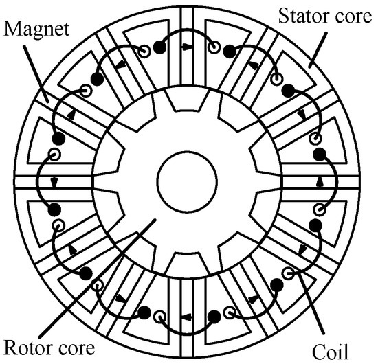
Figure 1.
The three-phase 12/10 conventional FSPM machine.
Recently, the operational principles and electromagnetic performance of FSPM machines, focusing on phase PM flux linkage, back electromotive force (EMF), cogging torque, winding inductances, electromagnetic torque, and torque ripple, have been widely and deeply analyzed [10,11,12,13]. However, as a relatively novel class of electrical machines, the design principles and parameter-determination procedures of FSPM machines are rather insufficient, especially for choosing the rules of the combinations of stator poles and rotor teeth, which limits further studies and applications of this kind of machine. J.T. Chen, and Z.Q. Zhu used an analytical method to evaluate the electromagnetic performance of FSPM machines with different stator pole and rotor teeth combinations, covering from two-phase to six-phase, and the corresponding winding factors of possible combinations were calculated [14,15]. The conclusion drawn in [14] is that the relationship between stator poles (Ps) and rotor teeth (Pr) is Pr = Ps ± 2 or Pr = Ps ± 1, which is definitely helpful for the design of FSPM machines. L. Shao and W. Hua analyzed 12-phase 24/20, 24/22, 24/26, and 24/26 FSPM machines, and found that the 24/26 machine exhibited the highest electromagnetic torque and efficiency, while the 24/22 one had the smallest cogging torque, torque ripple, and efficiency [16]. H. Chen investigated the effect of winding configurations on the performance of a five-phase outer-rotor FSPM machine, including single-layer, double-layer, and multi-layer winding configurations, and found that the FSPM machine with multi-layer winding exhibited better performance [17]. X. Zhu and W. Huang analyzed the feasible stator–rotor combination of five-phase FSPM machines considering flux leakage, back electromagnetic force quality, and unbalanced magnetic force [18]. D. Li, Y. Shi, and J. D. McFarland studied the Air-Gap Field Modulation theory, and then researched the optimal stator–rotor combinations of 6-, 12-, and 18-stator slot FSPM machines [19,20,21].
Despite these advances, there are still several limitations to the conclusions in the existing literature: (1) the investigated combinations are incomplete, such as the cases of Pr = Ps ± 3 (18/15, 18/21) and Pr = Ps ± 4 (24/20, 24/28) for conventional FSPM machines are not considered; (2) for some combinations, e.g., 6/4, 6/8, 18/16, and 18/20, the phase back-EMFs of armature windings are asymmetric because of no complementarity between coils, which are not covered; (3) the nature of “good” and “bad” combinations of stator poles and rotor teeth for conventional FSPM machines is not disclosed; and (4) a general principle to determine the optimal combinations of FSPM machines regardless of phase numbers is not proposed.
To address these gaps, this paper proposes an analytical model to optimize two critical static characteristics based on coil complementarity, namely symmetrical phase back-EMF and large electromagnetic torque. The analytical model enables the general determination of the optimal combinations of stator poles and rotor teeth for FSPM machines with prime phase numbers. Meanwhile, for the FSPM machines with composite phase numbers, such as four, six, nine, and twelve phases, the combinations can be derived from the machines with prime phase numbers. Notably, single-phase FSPM machines are excluded from this series, as the proposed prime phase principles apply to them directly.
The proposed principles are rooted in coil complementarity theory. Therefore, in the following, firstly, the coil complementarity and coil-EMF vectors are introduced and illustrated in Section 2. Then, a general model that can determine the optimal combinations of stator poles and rotor teeth for conventional FSPM machines with prime phase numbers is proposed and implemented by different examples, including two-phase, three-phase, and five-phase systems, where the predicted electromagnetic performances by 2-D finite element analysis (FEA) verify the feasibility and effectiveness of the general model in Section 3. Thereafter, in Section 4, the winding factors of the FSPM machines with prime phase numbers for different stator poles and rotor teeth combinations are calculated and evaluated. Finally, conclusions on stator pole and rotor teeth combination principles for flux-switching brushless machines with prime phase numbers are summarized in Section 5.
2. Coil Complementarity and Coil-EMF Vectors
For the FSPM machines, coil complementarity is an important characteristic [12], which is the basis of the following investigations on combinations of stator poles and rotor teeth.
2.1. Coil Complementarity and Coil Pair
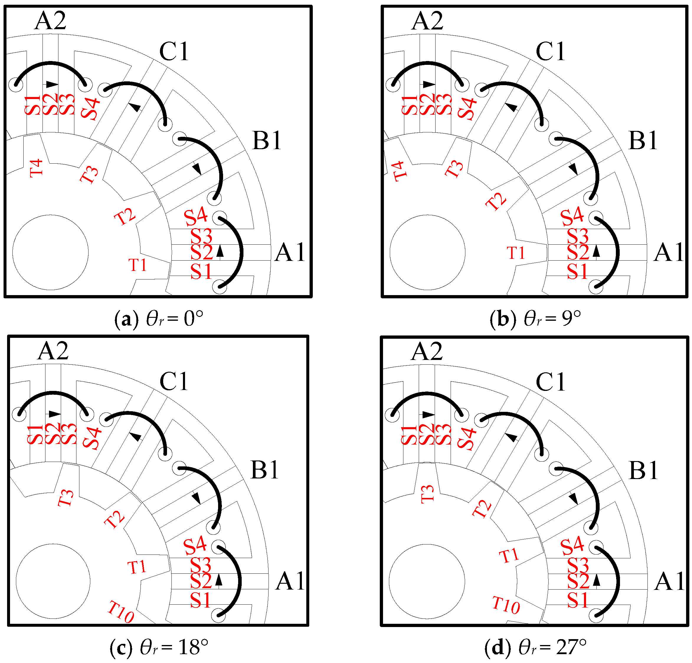
In order to gain a clearer understanding of coil complementarity, the three-phase 12/10 conventional FSPM machine shown in Figure 1 is exemplified to illustrate the phenomenon and effect of coil complementarity, and the detailed analysis process can be found in reference [12]. Since the rotor teeth number Pr = 10, the resultant electrical cycle of the 12/10 machine is 36° in mechanical degrees. Supposing the referenced direction of rotor rotation is anticlockwise and the initial rotor position θr = 0° is defined in Figure 2a, the rotor moves in the way of 0°→9°→18°→27°→36° (0°), which corresponds to the four typical rotor positions (a)→(b)→(c)→(d)→(a), as shown in Figure 2. For coil A1, the relative variation in the alignment region between the rotor tooth (T1) and the stator pole P1 wound by coil A1 is S1→S2→S3→S4→S1 (even when the corresponding rotor tooth is T10), whereas for the other coil A2, the alignment regions between the rotor teeth and the stator pole P2 wound by coil A2 are followed as S1→S2→S3→S4→S1.
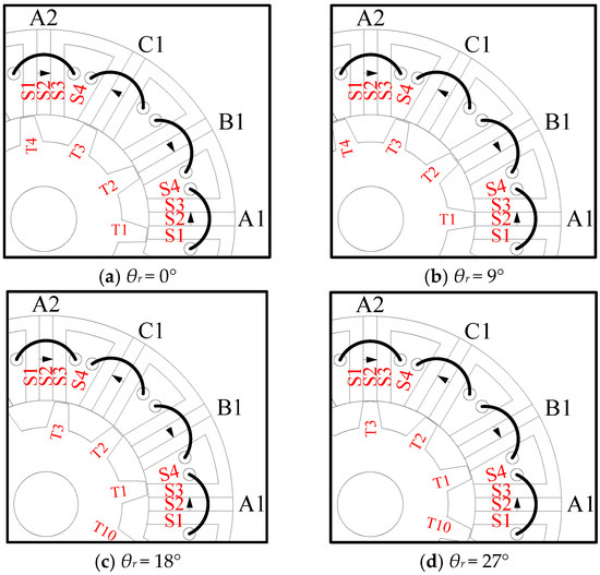
Figure 2.
Four typical rotor positions of the 12/10 FSPM machine.
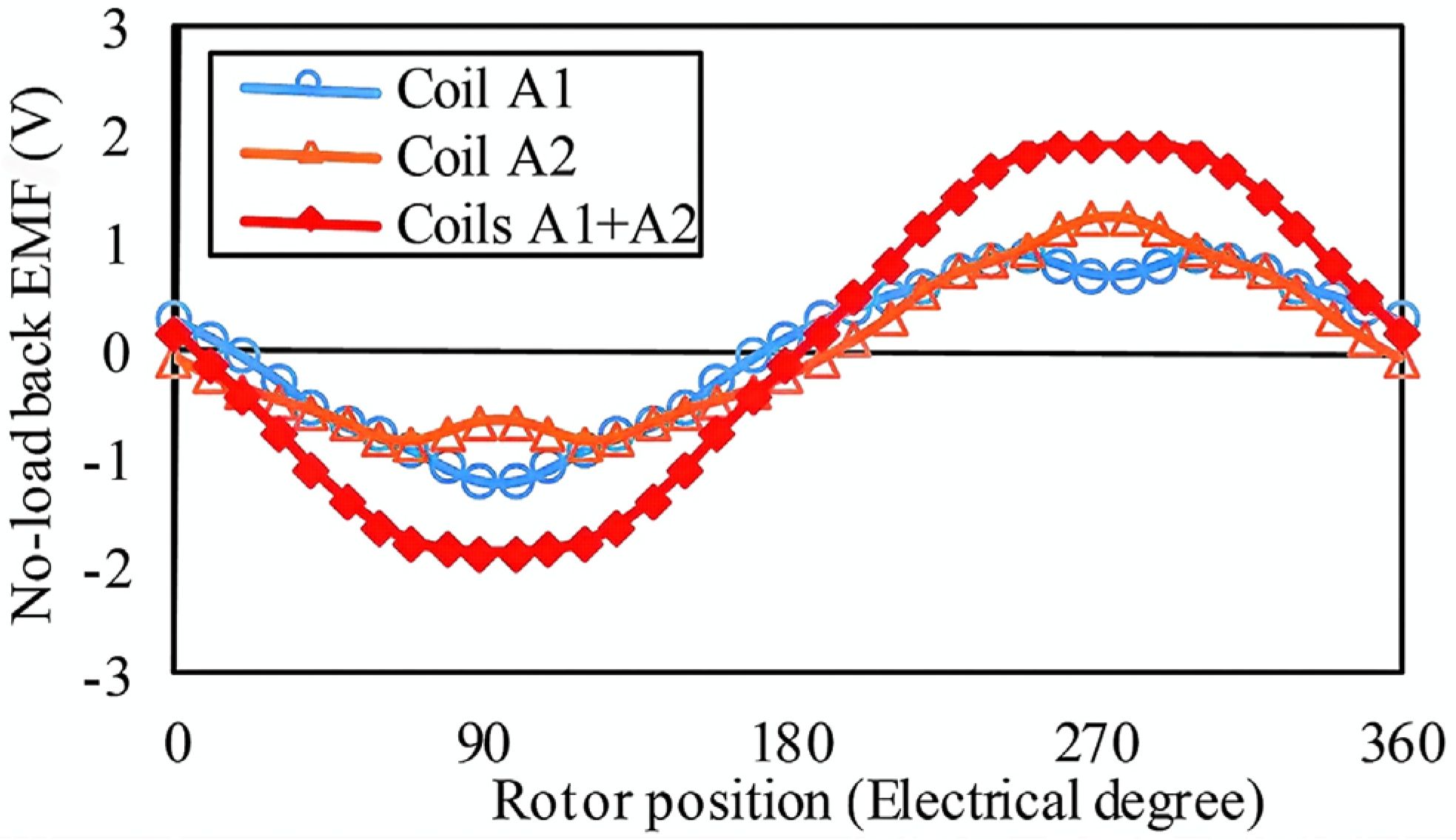
Comparing the variation processes of the above relative alignment region between the rotor teeth and coil A1 and coil A2, the variation directions are exactly reversed, which could be reflected by the back-EMF waveforms of coils A1 and A2 by FEA, as shown in Figure 3. Obviously, both back-EMF waveforms of coils A1 and A2 are asymmetrical; however, the combined coil group back-EMF waveform (coils A1 + A2) due to coils A1 and A2 is symmetrical and sinusoidal. Namely, the electromagnetic performances of coils A1 and A2 are complementary, and the dominant even-order harmonics can compensate each other, resulting in an improved coil group back-EMF waveform when the two coils are serially connected to form a coil group. Considering a symmetrical phase back-EMF is essential for the high-performance control of FSPM machines, coils A1 and A2 are defined as an impartible coil pair and connected serially to guarantee the symmetry of the phase back-EMF waveform, which is the basis for the following analysis.
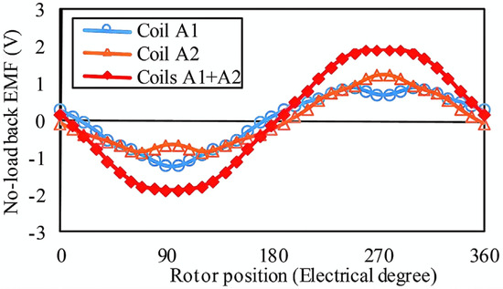
Figure 3.
Coil back-EMFs per turn of the 12/10 FSPM machine at 1500 r/min.
2.2. Coil-EMF Vectors
The coil-EMF vectors for the armature coils are the basis of coil connections. The coil-EMF vectors will be determined if the phase angles of the coil-EMF vectors are calculated. In the following analysis, the phase angles of the vectors are calculated first.
For conventional FSPM machines, each stator pole is wound by a concentrated armature coil, namely Ps = Psc, where Ps is the number of stator poles and Psc is the number of stator coils. The stator coils are anticlockwise marked as 1, 2, …, Psc − 1, Psc, and the mechanical angle between two adjacent coils, namely θs, is exhibited in Equation (1).
Moreover, θ(n) is defined as the phase angle of the coil-EMF vector of the stator coil n, and the phase angle of coil 1 is set as 0°, namely, θ(1) = 0°. When n is odd, the polarity of the permanent magnet wound by the coil n is the same as n = 1; otherwise, it is opposite when n is even. Hence, θ(n) can be generalized, as expressed by Equation (2), where Pr is the number of rotor teeth.
The number of coils per pole per phase (NCPP) q is a fraction, and can be expressed in a general term as
where nq, dq, q0, nq′ are integral numbers, respectively. nq and dq have no common divisor, and in the second form nq′ < dq. The fractional-slot winding can be equivalent to an integral-slot winding by multiplying dq for Equation (3), and the equivalent number of coils per pole per phase (ENCPP), namely q′, is
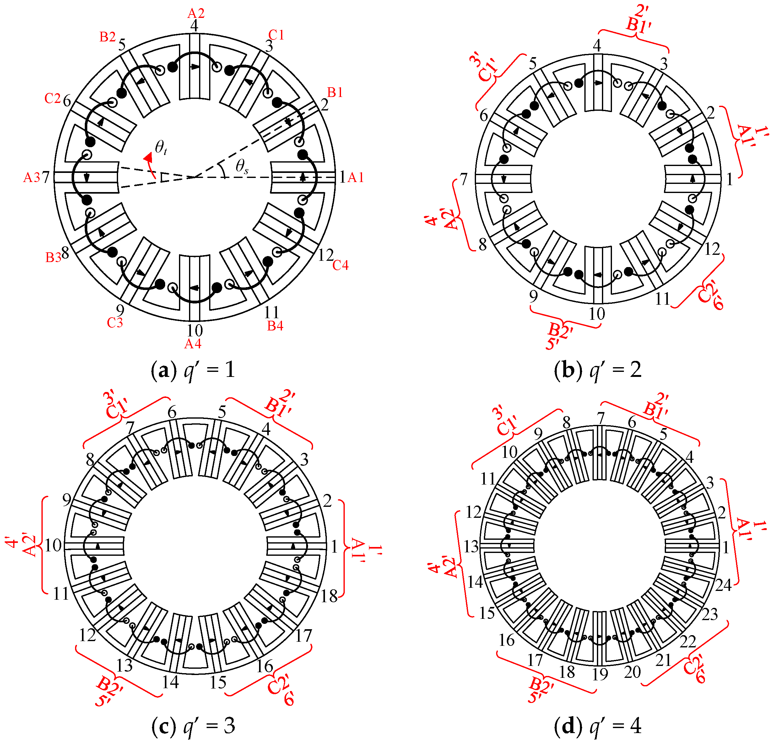
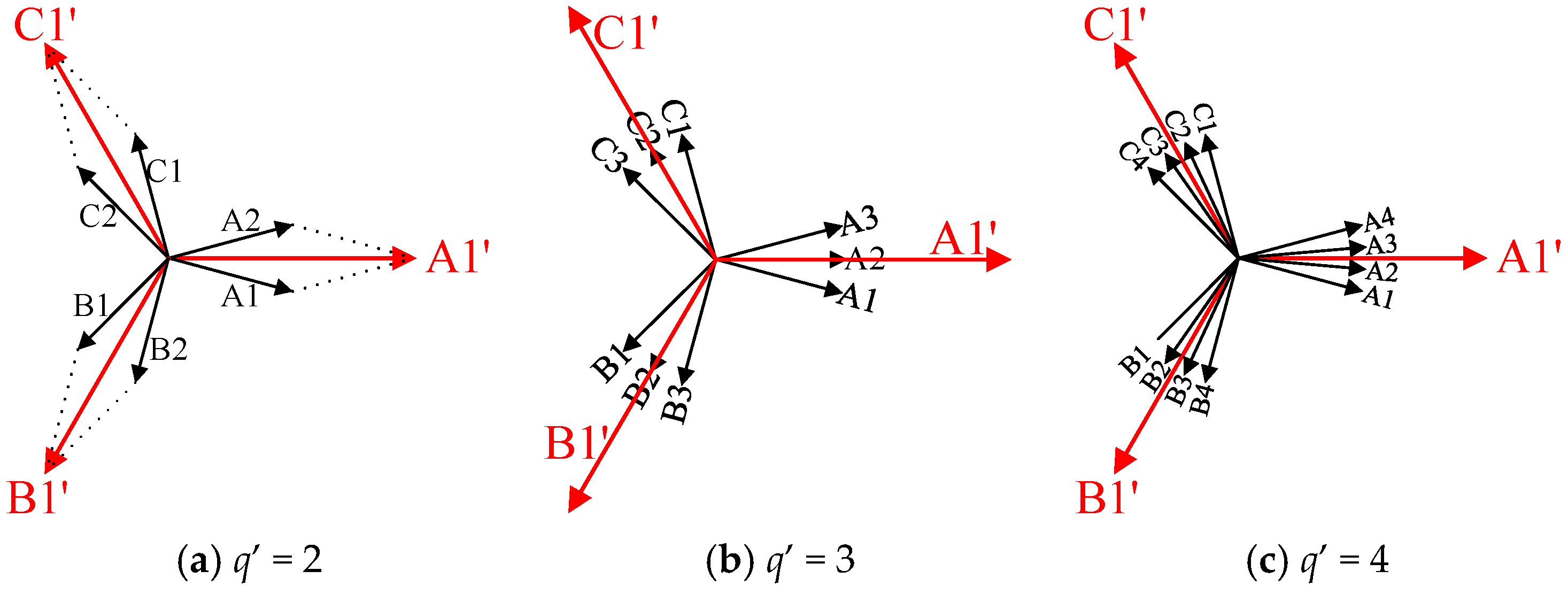
Four examples are taken in Figure 4 to illustrate the relationship between coil connections and q′, where the rotors of four machines are not shown to make the coil connections clearer. Figure 4a refers to a conventional 12/10 FSPM machine, where ENCPP q′ = 1 based on Equations (3) and (4) (Psc = 12, m = 3, Pr = 10, q = 1/5, nq = 1, dq = 5, q0 = 0, nq′ = 1, q′ = 1). Similarly, Figure 4b–d refer to the coil connections of conventional 12/11, 18/17, and 24/23 FSPM machines, where the ENCPPs are, respectively, q′ = 2, q′ = 3, and q′ = 4. It can be seen that for q′ = 1, the two adjacent coils belong to different phases, namely connection “A1B1C1”-“A2B2C2”-“A3B3C3”-“A4B4C4”, while for q′ = 2, q′ = 3, and q′ = 4, two, three, and four consecutively adjacent coils belong to the same phase, being the connections “AA-BB-CC”, “AAA-BBB-CCC”, and “AAAA-BBBB-CCCC”, respectively.
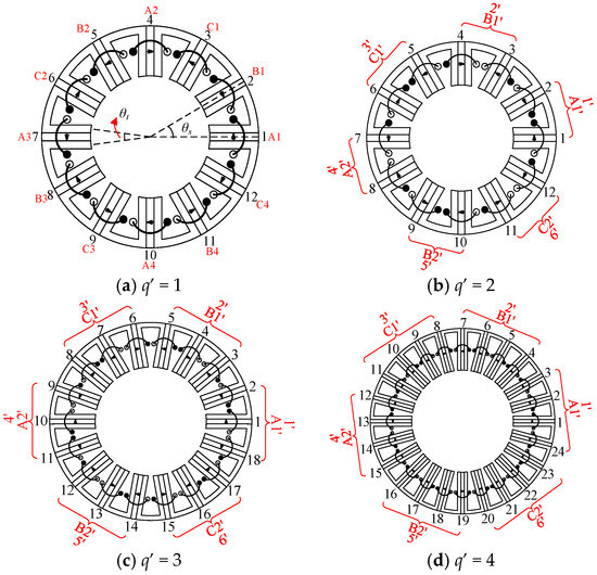
Figure 4.
Coil connections with different q′.
2.3. Equivalent Coil-EMF Vectors
For the FSPM machines with q′ > 1, such as the topologies in Figure 4b–d, the consecutively adjacent stator coils belonging to the same phase can be regarded as an equivalent coil to simplify the coil connections. Therefore, the mechanical angle of the adjacent two equivalent coils is defined as θs′, and all the equivalent coils are anticlockwise marked as 1′, 2′,3′, …. When q′ is even, the polarities of permanent magnets for all the equivalent coils are the same, e.g., q′ = 2 shown in Figure 4b, the polarities of the six equivalent coils are, respectively, NS, NS, NS, NS, NS, and NS, which are all the same. While q′ is odd, the polarities of permanent magnets for the adjacent equivalent coils are opposite. Such as q′ = 3 shown in Figure 4c, the polarities of the adjacent two equivalent coils are, respectively, NSN and SNS, which are opposite. Hence, the phase angle of the equivalent coil-EMF vector is defined as θ′(n′), where n′ is the number of equivalent coils.
When q′ is odd, θ′(n′) is
When q′ is even, θ′(n′) is
Hence, θ′(n′) can be expressed as
Based on the foregoing analysis, the phase angle of the coil-EMF vectors for coil n, namely θ(n), and the phase angle of the coil-EMF vectors for equivalent coil n′ with q′ > 1, namely θ′(n′), are calculated, which are used to establish the model determining the optimal combinations of stator poles and rotor teeth for conventional FSPM machines in the next section.
3. Stator Pole and Rotor Teeth Combinations of Conventional FSPM Machines
In this section, combinations of stator poles and rotor teeth for conventional FSPM machines with prime phase numbers, namely two, three, and five phases, are investigated by a model.
3.1. Combinations of Stator Poles and Rotor Teeth Model
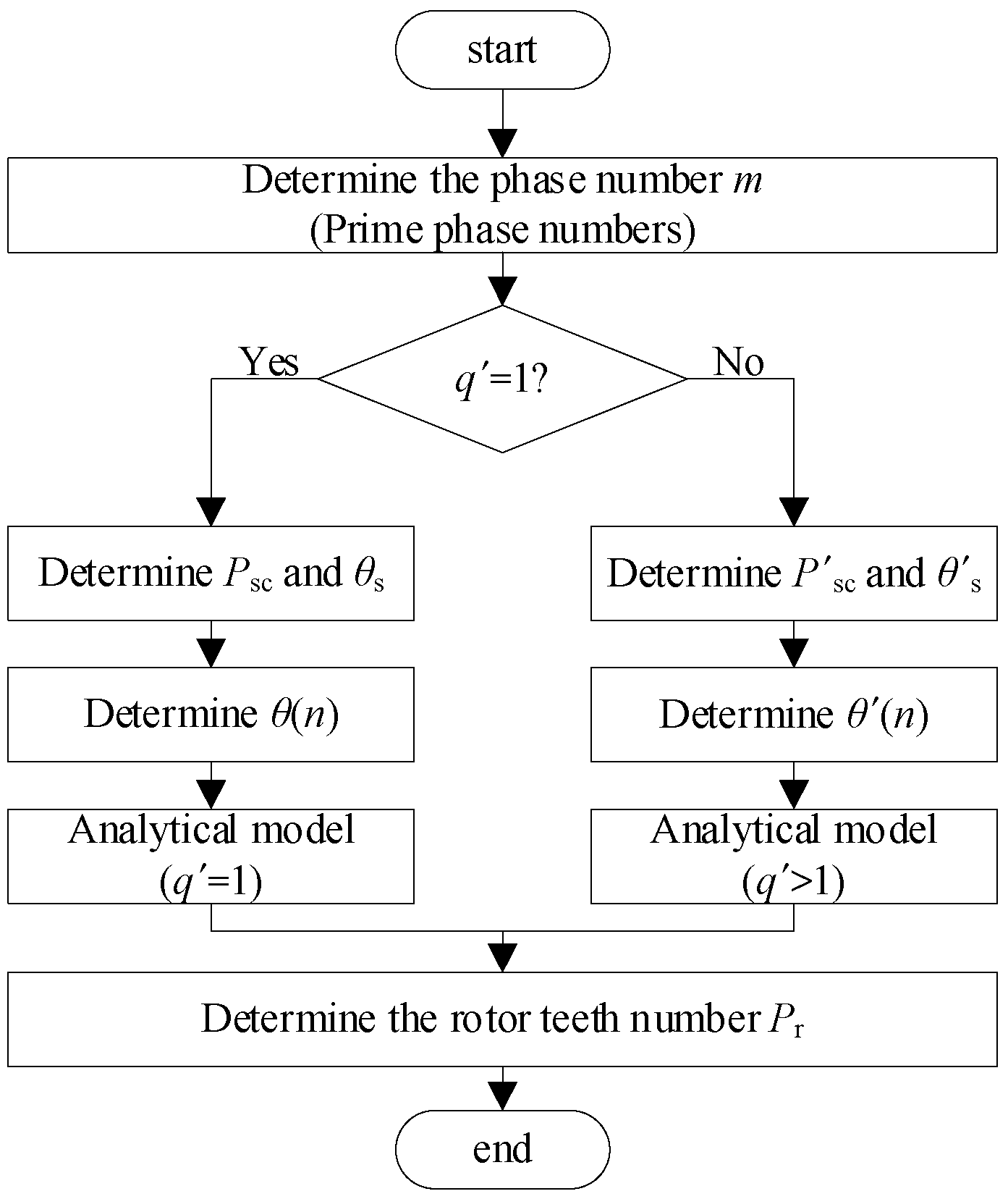
From the above analysis, it can be found that the winding connections can be briefly classed into two types, namely, q′ = 1 and q′ > 1, according to the number of consecutively adjacent coils belonging to the same phase. For the topologies with q′ > 1, the consecutively adjacent coils belonging to the same phase are considered as one equivalent coil. The flow chart of the analytical model for stator–rotor combinations is shown in Figure 5.

Figure 5.
Flow chart of analytical model for stator–rotor combinations.
3.1.1. q′ = 1
When q′ = 1, the number of all coils Psc is exhibited in Equation (8) where m is the phase number, and K is the number of coil pairs exhibiting complementarity, which is an integer, e.g., 1, 2, etc. Substituting Equation (8) into (1), the angle between two adjacent armature coils is obtained as Equation (9).
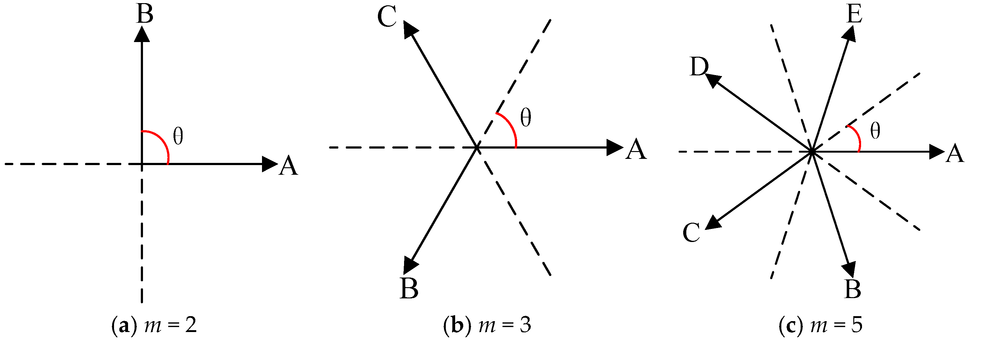
Figure 6 shows the minimum angles between two vectors for the machines with different phase numbers. For two-phase, three-phase, and five-phase machines, the minimum angles are θ = π/2, θ = π/3, and θ = π/5, namely θ = HCF (2π/m, π), where HCF is the highest common factor. For the topologies with q′ = 1, the two adjacent armature coils belong to different phase windings, namely, the coil-EMF vectors of two adjacent coils are different. Since the phase angle of the coil-EMF vector for coil 1 is 0°, namely, θ(1) = 0°, the phase angle of the coil-EMF vector for coil 2, namely θ(2), should be an integer multiple of the minimum angle θ, namely satisfying Equation (10). In addition, the phase angle of the coil-EMF vector for coil 2 should not be integer multiples of π, namely satisfying Equation (11), since it will just constitute a single-phase machine if θ(2) is an integer multiple of π.
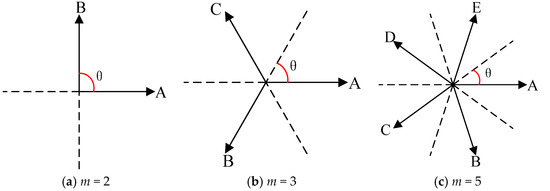
Figure 6.
Minimum angle between two vectors of FSPM machines with different phase numbers.
Moreover, it can be seen from Figure 2b,d, the coils A1 and A2, comprising a coil group, have complementarity, and when one coil aligns with the rotor teeth, the other coil will align with the rotor slot, namely the corresponding rotor positions for coils A1 and A2 are different. Hence, for the machine with K coil groups, Pr/K should be an odd number, namely satisfying Equation (12). Otherwise, the rotor positions corresponding to coils A1 and A2 are the same, resulting in coils A1 and A2 having no complementarity.
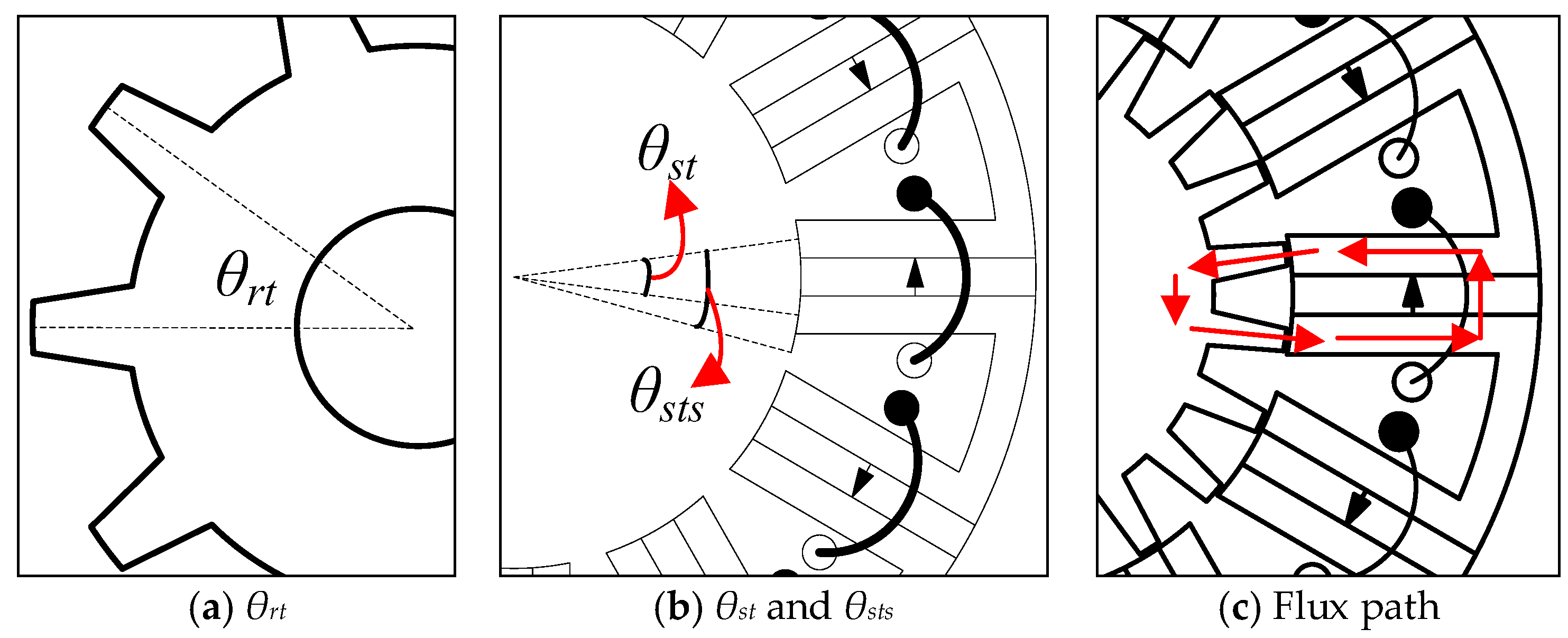
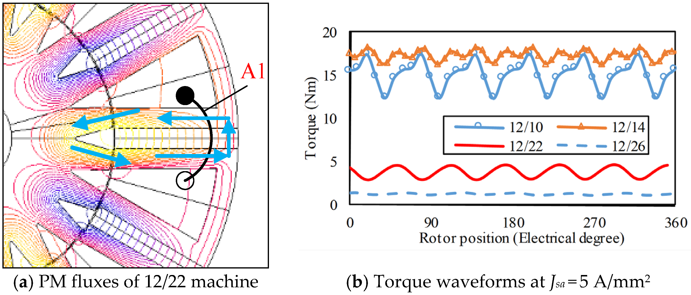
Figure 7 exhibits several parameters of the stator and rotor where θrt is the mechanical angle between two adjacent rotor teeth, θst is the mechanical angle between two stator teeth of one stator pole, and θsts is the mechanical angle between the stator tooth and stator slot, which is about 3θst/2. Three parameters are calculated, shown in Equations (13)–(15), where Ps = Psc since each stator pole is wound by a stator coil for conventional FSPM machines. In order to obtain enough electromagnetic torque, θrt should not be close to θst and θrt has to satisfy θrt ≥ θsts. If θrt and θst are close, as shown in Figure 7c, the PM flux linkage flows into and then flows out of the coil, leading to a smaller effective flux linkage of the armature coil. Taking q′ = 1 and m = 3 as an example (Psc = 12), the 12/10, 12/14, 12/22, and 12/26 FSPM machines all satisfy the Equations (10)–(12). But for 12/22 and 12/26 topologies, θrt and θst are quite close; the electromagnetic performances of four machines by FEA are shown in Figure 8, where the PM flux linkage of coil A1 flows into and then flows out of the coil, leading to a smaller effective flux linkage of coil A1, which causes the torques of the 12/22 and 12/26 machines to be distinctly smaller than those of the 12/10 and 12/14 ones.
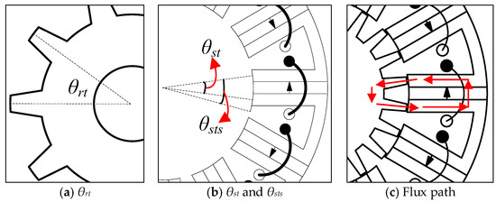
Figure 7.
Several parameters of the stator and rotor.
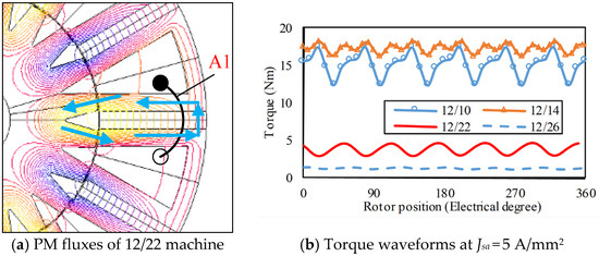
Figure 8.
Comparison of four FSPM machines with 12/10, 12/14, 12/22, and 12/26 combinations.
In addition, since the machine has K coil pairs, the number of rotor teeth, namely Pr, must be bigger than mK, namely θrt < 2π/mK. Hence, θrt has to satisfy Equation (16). Substituting Equations (13)–(15) into Equation (16), the range of Pr is obtained as Equation (17).
Through the above analysis, the back-EMF waveforms would be symmetrical if the number of rotor teeth Pr satisfies Equations (10)–(12) and Equation (17). Therefore, the model determining the stator pole and rotor teeth combinations for conventional FSPM machines with prime phase numbers where q′ = 1 is shown in Equation (18).
3.1.2. q′ > 1
When q′ > 1, the adjacent q′ coils belonging to the same phase are considered as one equivalent coil. Like the machine in Figure 4b–d, only if the equivalent coils A1′ and A2′ had complementarity could the back-EMF waveforms be symmetrical. Hence, the number of equivalent coils Psc′ and the mechanical angle of adjacent equivalent coils θs′ are shown in Equations (19) and (20), where parameter K is the number of equivalent coil pairs.
For the topologies with q′ > 1, the two adjacent equivalent coils belong to different phase windings, namely, the coil-EMF vectors of two adjacent equivalent coils are different. Since the phase angle of the coil-EMF vector for equivalent coil 1 is 0°, namely, θ′(1) = 0°, the phase angle of the coil-EMF vector for coil 2, namely θ′(2), should be integer multiples of the minimum angle θ and should not be integer multiples of π, namely satisfying Equations (21) and (22), which are similar to the topologies with q′ = 1. Similarly, Pr is also limited by Equations (12) and (17).
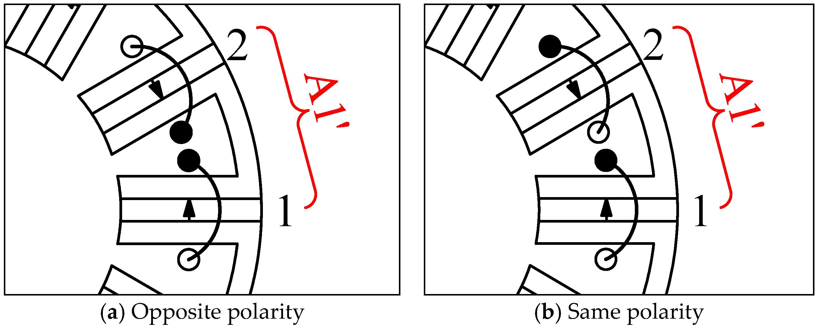
Comparing the equations with q′ = 1, some other equations need to be added. Firstly, the two adjacent coils in an equivalent coil should be connected in opposite polarity. Since the phase angle of coil 1 is θ(1) = 0°, the phase angle of coil 2, θ(2), has to satisfy Equation (23), where T is an integer number. Taking q′ = 2 as an example, the two adjacent coils belonging to the same phase will be connected into the opposite polarity shown in Figure 9a if satisfying Equation (23), and connected into the same polarity in Figure 9b if not satisfying (23). If the coils are connected in the same polarity, the currents in the stator slot between stator poles 1 and 2 are opposite, which leads to the uselessness of the slot. Secondly, the phase angle of coil 2, namely θ(2), should be as close to 180° as possible, namely the minimum of cos(θ(2)), shown in (24), to obtain a larger winding factor.
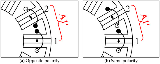
Figure 9.
Coil connections for q′ = 2.
Through the above analysis, the back-EMF waveforms would be symmetrical and the magnitude of the electromagnetic torque would be large enough if the number of rotor teeth Pr satisfies the Equations (12), (17), and (21)–(24). Therefore, the model determining the stator pole and rotor teeth combinations for conventional FSPM machines with prime phase numbers where q′ > 1 is shown in Equation (25).
Based on the models in (18) and (25), the obtained combinations of stator poles and rotor teeth satisfy Equation (26), where it should be noted that the parameter K is the number of coil pairs exhibiting complementarity for q′ = 1 and the number of equivalent coil pairs for q′ > 1.
In the following analysis, the conventional FSPM machines with prime phases, such as two, three, and five phases, are simulated by FEA to verify the conclusion obtained by the above models.
3.2. Three-Phase Conventional FSPM Machines
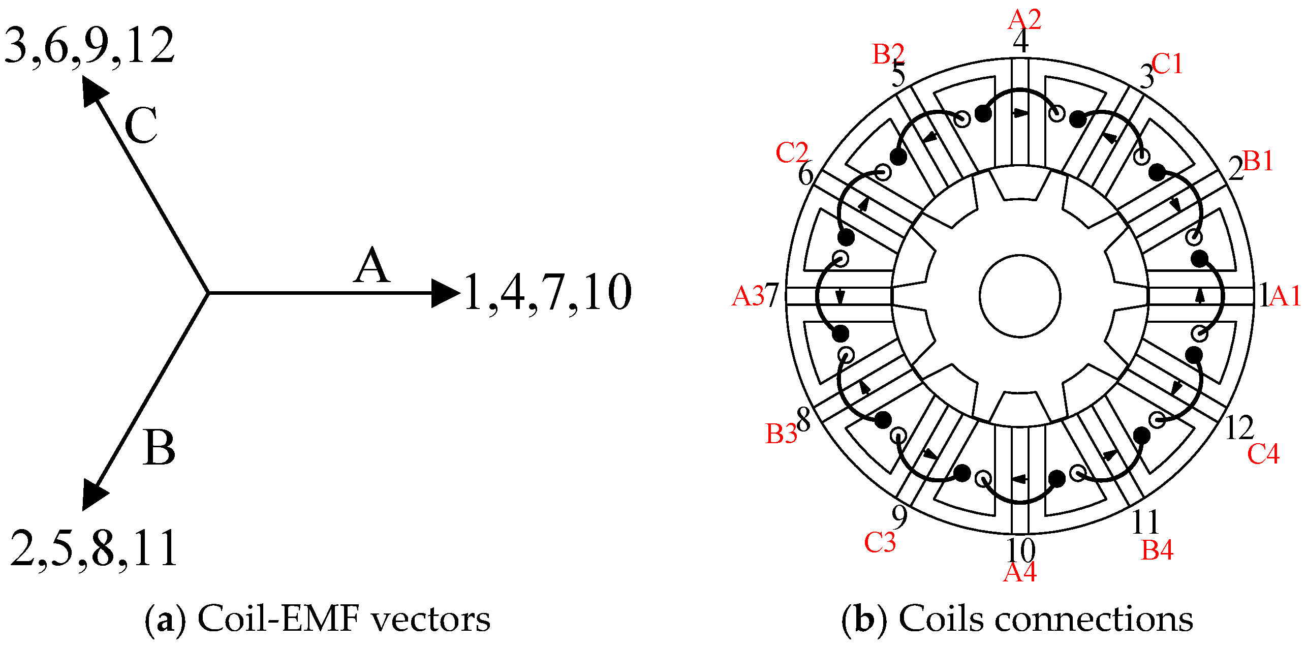
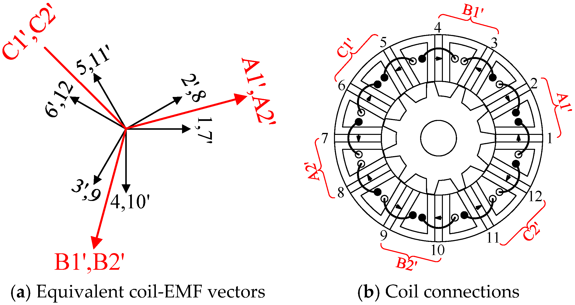
When q′ = 1, the stator coil connection is A-B-C-A. Based on the model in Equation (18), when K = 1, the optimal combinations of stator and rotor poles are 6/5 and 6/7, where the numbers of stator poles and rotor teeth, respectively, Ps and Pr, satisfy Equation (26). When K = 2, the obtained optimal combinations of stator poles and rotor teeth are 12/10 and 12/14, where the parameters Ps and Pr also satisfy Equation (26). And 18/15 and 18/21 are the optimal combinations for K = 3, while 24/24 and 24/28 are for K = 4. In addition, the parameters Ps and Pr satisfy Equation (26). Taking K = 2 as an example, the coil-EMF vectors and coil connections of the conventional 12/10 machine are listed in Figure 10.

Figure 10.
Winding configuration of the conventional 12/10 FSPM machine.
When q′ = 2, the stator coil connection is AA-BB-CC-AA. The two adjacent coil-EMF vectors synthesize into an equivalent coil-EMF vector, as shown in Figure 11a, where K is the number of equivalent coil pairs. Based on the model in Equation (25), when K = 1, the optimal combinations of stator poles and rotor teeth are 12/11 and 12/13, where Ps and Pr satisfy Formula (26). The combinations 24/22 and 24/26 are the optimal combinations for K = 2, while 36/33 and 36/39 are for K = 3, where the parameters Ps and Pr both satisfy Formula (26). The coil-EMF vector and coil connections of conventional 12/11 FSPM machines are listed in Figure 12 as an example.
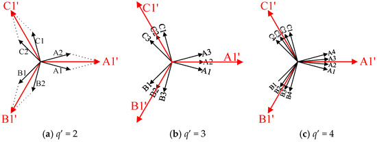
Figure 11.
Equivalent coil-EMF vectors of machines with different q′.
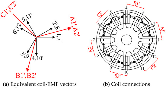
Figure 12.
Winding configuration of the conventional 12/11 FSPM machines.
When q′ = 3, the stator coil connection is AAA-BBB-CCC-AAA. The three adjacent coil-EMF vectors synthesize into an equivalent coil-EMF vector, as shown in Figure 11b. Based on the model in Equation (25), when K = 1, the optimal combinations of stator and rotor poles are 18/17 and 18/19, where Ps and Pr satisfy Equation (26). When K = 2, the obtained optimal combinations are 36/34 and 36/38, where the parameters Ps and P also satisfy Equation (26). The coil-EMF vectors and coil connections of conventional 18/17 FSPM machines are listed in Figure 13.
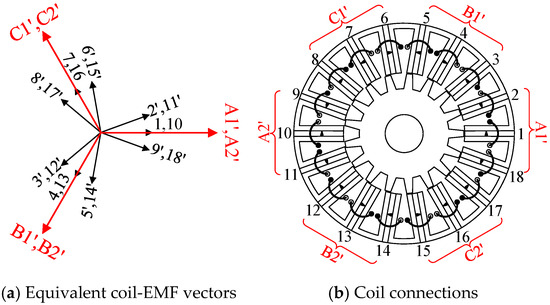
Figure 13.
Winding configuration of the conventional 18/17 FSPM machines.
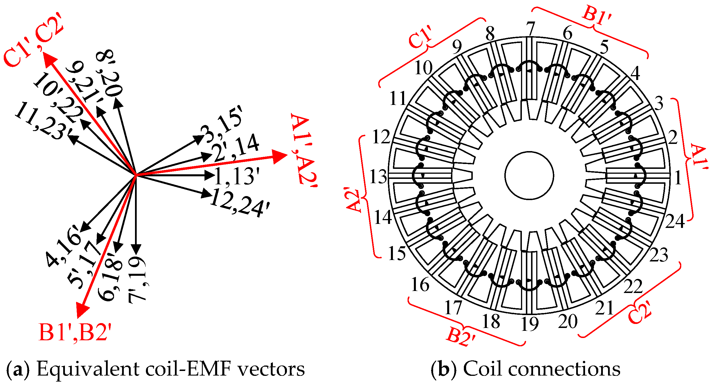
When q′ = 4, the stator coil connection is AAAA-BBBB-CCCC-AAAA. The four adjacent coil-EMF vectors synthesize into an equivalent coil-EMF vector, as shown in Figure 11c. Based on the model in Equation (25), when K = 1, the optimal combinations of stator poles and rotor teeth are 24/23 and 24/25, whose back-EMF waveforms are symmetrical and sinusoidal. And Ps and Pr satisfy Equation (26). When K = 2, the obtained optimal combinations of stator and rotor poles are 48/46 and 48/50, where the parameters Ps and Pr also satisfy Equation (26). The coil-EMF vectors and coil connections of the 24/23 machine are listed in Figure 14 as an example.
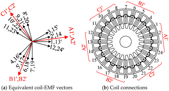
Figure 14.
Winding configuration of the conventional 24/23 machine.
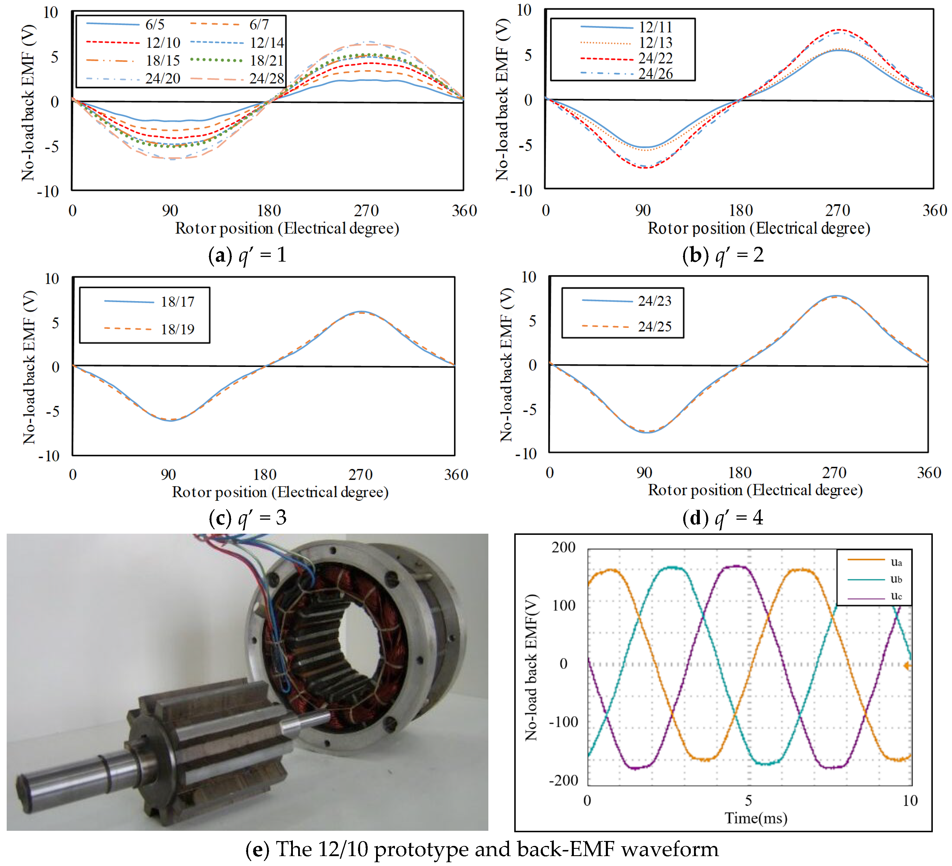
The simulated back-EMF waveforms by FEA of three-phase machines with q′ = 1, q′ = 2, q′ = 3, and q′ = 4 are, respectively, exhibited in Figure 15. And a 12/10 prototype and its back-EMF waveforms using a Tektronix oscilloscope are shown in Figure 15e, which shows that the back-EMF waveforms of the obtained combinations are all symmetrical.
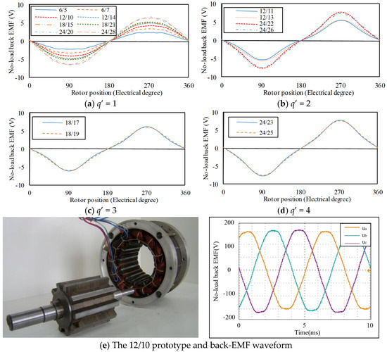
Figure 15.
Back-EMF waveforms of machines with different q′ and 12/10 prototype.
3.3. Two-Phase Conventional FSPM Machines
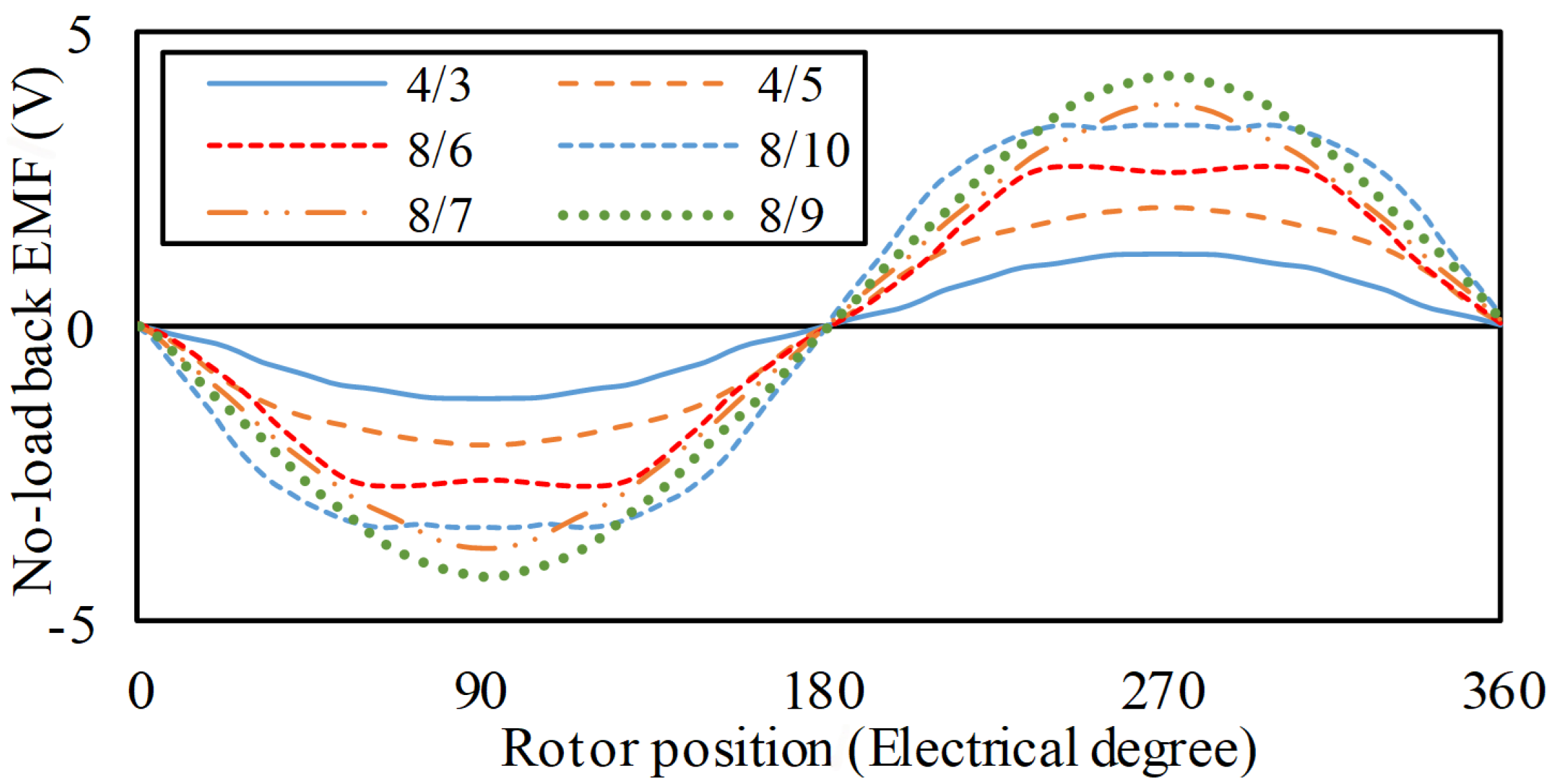
The models shown in Equations (18) and (25) are also suitable for two-phase machines. When q′ = 1, based on the model in Formula (18), the available configurations are 4/3 and 4/5 for K = 1, 8/6 and 8/10 for K = 2, and 12/9 and 12/15 for K = 3, which match with Equation (26). When q′ > 1, based on the model in Equation (25), the available configurations also match with Equation (26), for example, configurations 8/7 and 8/9 are suitable for q′ = 2 and K = 1, and configurations 16/14 and 16/18 are suitable for q′ = 2 and K = 2.
As is shown in Figure 16, the FE-predicted back-EMF waveforms of the conventional two-phase topologies with q′ = 1, namely, 4/3, 4/5, 8/6, and 8/10, and topologies with q′ = 2, namely, 8/7 and 8/10, are all symmetrical.
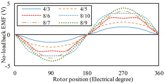
Figure 16.
FE-predicted back-EMF waveforms of two-phase topologies.
3.4. Five-Phase Conventional FSPM Machines
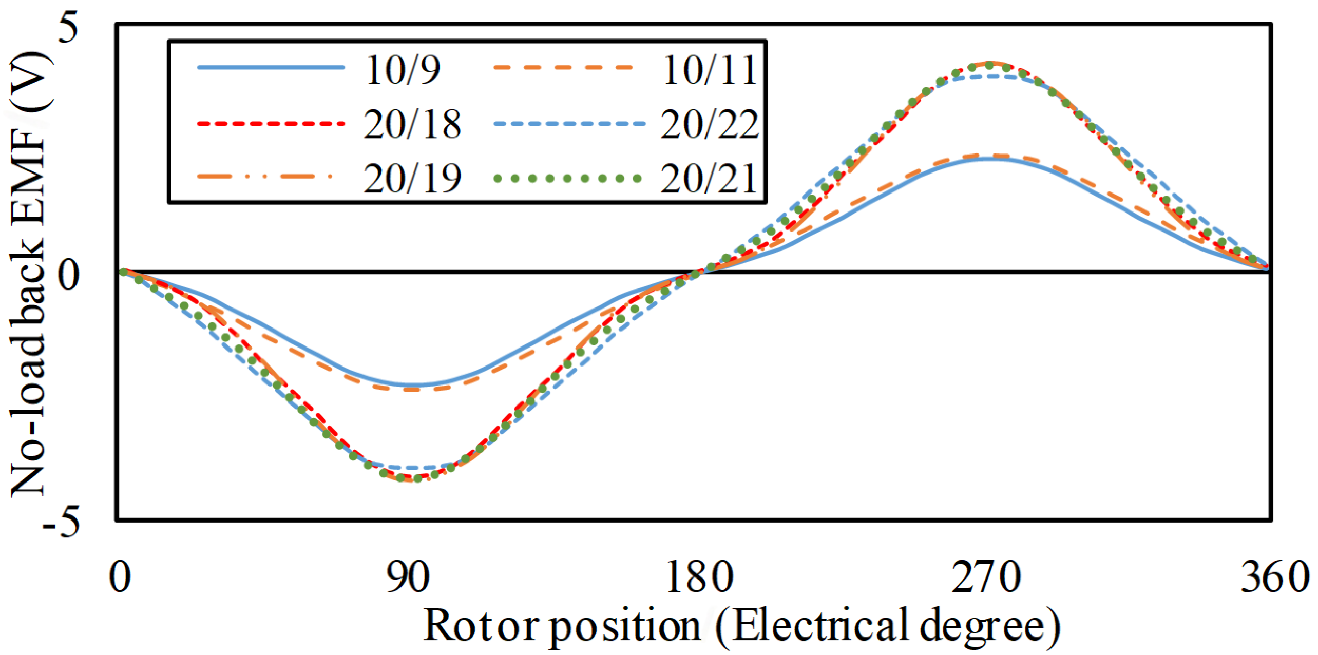
For five-phase conventional machines, the models (18) and (25) are also useful to determine the optimal stator pole and rotor teeth combinations. When q′ = 1 and K = 1, based on the model in Equation (18), the configurations 10/7, 10/9, 10/11, and 10/17 are obtained, whose back-EMFs are all symmetrical. Hence, for five-phase machines, more than two combinations have symmetrical back-EMF waveforms, whereas for two- and three-phase topologies, only two combinations have symmetrical back-EMF waveforms. Since the torque is larger when Pr is close to Ps, the configurations 10/9 and 10/11 are the most optimal stator and rotor pole combinations, which satisfy Formula (26). Similarly, when q′ = 1 and K = 2, the optimal stator pole and rotor teeth combinations are 20/18 and 20/22, which also satisfy Equation (26). When q′ = 2, the optimal stator pole and rotor teeth combinations are 20/19 and 20/21 for K = 1, and 40/38 and 40/42 for K = 2, which also satisfy Equation (26).
The five-phase topologies with q′ = 1 covering 10/9, 10/11, 20/18, and 20/22, and topologies with q′ = 2 including 20/19 and 20/21, are investigated by FEA. And the predicted back-EMF waveforms shown in Figure 17 are all symmetrical.
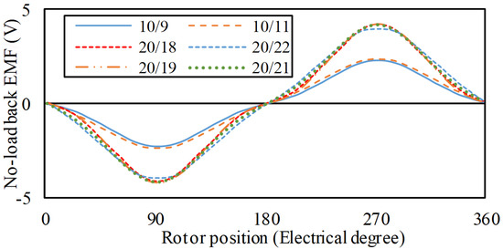
Figure 17.
FE-predicted back-EMF waveforms of five-phase topologies.
It can be distinctly seen from the above FE-predicted results that the conventional FSPM topologies with prime phase numbers, whose stator pole and rotor teeth combinations are determined by the proposed models, satisfy Pr = Ps ± K and exhibit symmetrical back-EMF waveforms, which illustrate the validity of the models.
4. Winding Factors
Winding factors include the distribution factor and pitch factor. The distribution factor kd is given in papers [14,22]:
where Q is the number of the fewest EMF vectors per phase, α is the angle between two adjacent vectors, and v is the order of the harmonic. The parameter α is given in Equation (28), and m is the phase number for prime phase machines.
For the prime phase, Q = q′. And finally, the distribution factor kd is expressed as Equation (29).
The pitch factor kp can be calculated as follows:
where Ps = Psc = 2mKq′ for conventional FSPM machines.
Therefore, the winding factor kw can be given as follows.
Equation (31) illustrates that for conventional FSPM machines with prime phase numbers, the fundamental winding factors are just related to the parameters of m and q′. And the winding factors are calculated and listed in Appendix A, covering two-, three-, and five-phase machines.
5. Conclusions
In this paper, firstly, to obtain the symmetrical back-EMF, a general model for determining the optimal stator pole and rotor teeth combinations of conventional FSPM machines with prime phase numbers, namely, two-, three-, and five-phase machines, is established. The concluded relationship between the stator poles and rotor teeth is Pr = Ps ± K. Then, the FE-predicted results of the conventional FSPM machines, whose stator pole and rotor teeth combinations are determined by the proposed models, are all symmetrical, verifying the effectiveness of the proposed models. Afterwards, the winding factors of the conventional FSPM machines with prime phases and different combinations of stator poles and rotor teeth are calculated.
In this paper, the stator pole and rotor teeth combinations of the conventional FSPM machines with prime phase numbers are determined by the proposed models based on coil complementarity. However, for the conventional FSPM machines with composite phase numbers, four-, six-, nine-, twelve-phase machines, etc., the optimal stator pole and rotor teeth combinations of them cannot be obtained by the models proposed in this paper, but they can be deduced from the results of the machines with prime phase numbers.
Author Contributions
Conceptualization, C.G. and X.J.; methodology, M.C.; software, W.H.; validation, C.G., X.J. and G.Z.; formal analysis, C.G. and X.J.; data curation, M.C.; writing—original draft preparation, C.G. and X.J.; writing—review and editing, W.H.; investigation, G.Z.; resources, W.H.; C.G. and X.J. contributed equally to this work and should be considered co-first authors. All authors have read and agreed to the published version of the manuscript.
Funding
This research was supported in part by the 973 Program of China under Project 2013CB035603, the National Natural Science Foundation of China under Projects 51137001, 51322705.
Data Availability Statement
The original contributions presented in this study are included in the article. Further inquiries can be directed to the corresponding author.
Conflicts of Interest
The authors declare no conflicts of interest.
Abbreviations
The following abbreviations are used in this manuscript:
| FSPM | Flux-switching permanent magnet |
| FS | Flux switching |
| EMF | Electromotive force |
| back-EMF | Back electromotive force |
| FEA | Finite element analysis |
| NCPP | Number of coils per pole per phase |
| ENCPP | Equivalent number of coils per pole per phase |
Appendix A
The stator pole and rotor teeth combinations of conventional FSPM machines with prime phases, covering two, three, and five phases, and the corresponding fundamental winding factors are listed in Table A1.

Table A1.
Stator and rotor pole combinations and fundamental winding factors of conventional FSPM machines.
Table A1.
Stator and rotor pole combinations and fundamental winding factors of conventional FSPM machines.
| (1) Two-Phase | |||||||
| q′ | K | Ps = Psc = 2Kmq′ | Pr = Ps ± K | kd | kp | kw | |
| 1 | 1 | 4 | 3 | 1 | 0.707 | 0.707 | |
| 5 | |||||||
| 2 | 8 | 6 | |||||
| 10 | |||||||
| 3 | 12 | 9 | |||||
| 15 | |||||||
| 4 | 16 | 12 | |||||
| 20 | |||||||
| 5 | 20 | 15 | |||||
| 25 | |||||||
| 2 | 1 | 8 | 7 | 0.924 | 0.924 | 0.854 | |
| 9 | |||||||
| 2 | 16 | 14 | |||||
| 18 | |||||||
| 3 | 24 | 21 | |||||
| 27 | |||||||
| 4 | 32 | 28 | |||||
| 36 | |||||||
| 3 | 1 | 12 | 11 | 0.911 | 0.966 | 0.88 | |
| 13 | |||||||
| 2 | 24 | 22 | |||||
| 26 | |||||||
| 3 | 36 | 33 | |||||
| 39 | |||||||
| 4 | 1 | 16 | 15 | 0.906 | 0.981 | 0.889 | |
| 17 | |||||||
| 2 | 32 | 30 | |||||
| 34 | |||||||
| (2) Three-phase | |||||||
| q′ | K | Ps = Psc = 2Kmq′ | Pr = Ps ± K | kd | kp | kw | |
| 1 | 1 | 6 | 5 | 1 | 0.866 | 0.866 | |
| 7 | |||||||
| 2 | 12 | 10 | |||||
| 14 | |||||||
| 3 | 18 | 15 | |||||
| 21 | |||||||
| 4 | 24 | 20 | |||||
| 28 | |||||||
| 5 | 30 | 25 | |||||
| 35 | |||||||
| 2 | 1 | 12 | 11 | 0.966 | 0.966 | 0.933 | |
| 13 | |||||||
| 2 | 24 | 22 | |||||
| 26 | |||||||
| 3 | 36 | 33 | |||||
| 39 | |||||||
| 4 | 48 | 44 | |||||
| 52 | |||||||
| 3 | 1 | 18 | 17 | 0.96 | 0.985 | 0.945 | |
| 19 | |||||||
| 2 | 36 | 34 | |||||
| 38 | |||||||
| 3 | 54 | 51 | |||||
| 57 | |||||||
| 4 | 1 | 24 | 23 | 0.958 | 0.991 | 0.95 | |
| 25 | |||||||
| 2 | 48 | 46 | |||||
| 50 | |||||||
| 3 | 72 | 69 | |||||
| 75 | |||||||
| 4 | 96 | 92 | |||||
| 100 | |||||||
| (3) Five-phase | |||||||
| q′ | K | Ps = Psc = 2Kmq′ | Pr = Ps ± K | kd | kp | kw | |
| 1 | 1 | 10 | 9 | 1 | 0.951 | 0.951 | |
| 11 | |||||||
| 2 | 20 | 18 | |||||
| 22 | |||||||
| 3 | 30 | 27 | |||||
| 33 | |||||||
| 4 | 40 | 36 | |||||
| 44 | |||||||
| 2 | 1 | 20 | 19 | 0.988 | 0.988 | 0.976 | |
| 21 | |||||||
| 2 | 40 | 38 | |||||
| 42 | |||||||
| 3 | 60 | 57 | |||||
| 63 | |||||||
| 3 | 1 | 30 | 29 | 0.985 | 0.995 | 0.98 | |
| 31 | |||||||
| 2 | 60 | 58 | |||||
| 62 | |||||||
| 3 | 90 | 87 | |||||
| 93 | |||||||
| 4 | 1 | 40 | 39 | 0.985 | 0.997 | 0.982 | |
| 41 | |||||||
| 2 | 80 | 78 | |||||
| 82 | |||||||
References
- Hoang, E.; Ahmed, B.; Lucidame, J. Switching flux permanent magnet polyphased synchronous machine. In Proceedings of the European Power Electronics Conference (EPE), Trondheim, Norway, 8–10 September 1997; pp. 903–908. [Google Scholar]
- Ozmen, T.; Ergun, B.; Gulbahce, M.; Onat, N. Rare-Earth Magnet Free Flux-Switching Generator for Wind Turbines in Micro-Grids: A Review. CES Trans. Electr. Mach. Syst. 2024, 8, 295–309. [Google Scholar] [CrossRef]
- Torkaman, H.; Ghaheri, A.; Keyhani, A. Design of Rotor Excited Axial Flux-Switching Permanent Magnet Machine. IEEE Trans. Energy Convers. 2018, 33, 1175–1183. [Google Scholar] [CrossRef]
- Nissayan, C.; Seangwong, P.; Chamchuen, S.; Fernando, N.; Siritaratiwat, A.; Khunkitti, P. Modeling and Optimal Configuration Design of Flux-Barrier for Torque Improvement of Rotor Flux Switching Permanent Magnet Machine. Energies 2022, 15, 8429. [Google Scholar] [CrossRef]
- Awah, C.C. Comparison of Partitioned Stator Switched Flux Permanent Magnet Machines Having Single- or Double-Layer Windings. IEEE Trans. Magn. 2016, 52, 9500310. [Google Scholar] [CrossRef]
- Du, Y.; Zou, C.; Zhu, X.; Zhang, C.; Xiao, F. A Full-Pitched Flux-Switching Permanent-Magnet Motor. IEEE Trans. Appl. Supercond. 2016, 26, 0604505. [Google Scholar] [CrossRef]
- Hwang, C.C.; Chang, C.M.; Hung, S.S.; Liu, C.T. Design of High Performance Flux Switching PM Machines with Concentrated Windings. IEEE Trans. Magn. 2014, 50, 4002404. [Google Scholar] [CrossRef]
- Mamashli, M.; Jamil, M. Enhanced Dynamic Control for Flux-Switching Permanent Magnet Machines Using Integrated Model Predictive Current Control and Sliding Mode Control. Energies 2025, 18, 1061. [Google Scholar] [CrossRef]
- Zhang, Z.; Guo, C. Model-Free Speed Control of Single-Phase Flux Switching Motor with an Asymmetrical Rotor. CES Trans. Electr. Mach. Syst. 2024, 8, 255–263. [Google Scholar] [CrossRef]
- Wu, Z.Z.; Zhu, Z.Q. Analysis of Air-Gap Field Modulation and Magnetic Gearing Effects in Switched Flux Permanent Magnet Machines. IEEE Trans. Magn. 2015, 51, 8105012. [Google Scholar] [CrossRef]
- Zhu, Z.Q.; Pang, Y.; Howe, D.; Iwasaki, S.; Deodhar, R.; Pride, A. Analysis of electromagnetic performance of flux-switching permanent magnet machines by non-linear adaptive lumped parameter magnetic circuit model. IEEE Trans. Magn. 2005, 41, 4277–4287. [Google Scholar] [CrossRef]
- Hua, W.; Cheng, M.; Zhu, Z.Q.; Howe, D. Analysis and optimization of back EMF waveform of a flux-switching permanent magnet motor. IEEE Trans. Energy Convers. 2008, 23, 723–733. [Google Scholar]
- Cheng, M.; Hua, W.; Zhang, J.Z.; Zhao, W.X. Overview of Stator-Permanent Magnet Brushless Machines. IEEE Trans. Ind. Electron. 2011, 58, 5087–5101. [Google Scholar] [CrossRef]
- Chen, J.T.; Zhu, Z.Q. Winding Configurations and Optimal Stator and Rotor Pole Combination of Flux-Switching PM Brushless AC Machines. IEEE Trans. Energy Convers. 2010, 25, 293–302. [Google Scholar] [CrossRef]
- Chen, J.T.; Zhu, Z.Q. Comparison of All- and Alternate-Poles-Wound Flux-Switching PM Machines Having Different Stator and Rotor Pole Numbers. IEEE Trans. Ind. Appl. 2010, 46, 1406–1415. [Google Scholar] [CrossRef]
- Shao, L.; Hua, W.; Zhu, Z.Q.; Tong, M.; Zhao, G.; Yin, F.; Wu, Z.; Cheng, M. Influence of rotor-pole number on electromagnetic performance in 12-phase redundant switched flux permanent magnet machines for wind power generation. IEEE Trans. Ind. Appl. 2017, 53, 3305–3316. [Google Scholar] [CrossRef]
- Chen, H.; Liu, X.; EL-Refaie, A.M.; Zhao, J.; Demerdash, N.A.O.; He, J. Comparative study of winding configurations of a five-phase flux-switching PM machine. IEEE Trans. Energy Convers. 2019, 34, 1792–1804. [Google Scholar] [CrossRef]
- Zhu, X.; Huang, W. Investigation of five-phase flux-switching permanent magnet machines for EV and HEV applications. IEEE Trans. Ind. Appl. 2024, 60, 1071–1082. [Google Scholar] [CrossRef]
- Li, D.; Qu, R.; Li, J.; Xu, W.; Wu, L. Synthesis of Flux Switching Permanent Magnet Machines. IEEE Trans. Energy Convers. 2016, 31, 1. [Google Scholar] [CrossRef]
- Shi, Y.; Jian, L.; Wei, J.; Shao, Z.; Li, W.; Chan, C.C. A New Perspective on the Operating Principle of Flux-Switching Permanent-Magnet Machines. IEEE Trans. Ind. Electron. 2016, 63, 1425–1437. [Google Scholar] [CrossRef]
- McFarland, J.D.; Jahns, T.M.; EL-Refaie, A.M. Analysis of the Torque Production Mechanism for Flux-Switching Permanent-Magnet Machines. IEEE Trans. Ind. Appl. 2015, 51, 3041–3049. [Google Scholar] [CrossRef]
- Bianchi, N.; Pr′e, M.D.; Alberti, L.; Fornasiero, E. Theory and Design of Fractional-Slot PM Machines; CLEUP: Padova, Italy, 2007. [Google Scholar]


Disclaimer/Publisher’s Note: The statements, opinions and data contained in all publications are solely those of the individual author(s) and contributor(s) and not of MDPI and/or the editor(s). MDPI and/or the editor(s) disclaim responsibility for any injury to people or property resulting from any ideas, methods, instructions or products referred to in the content. |
© 2025 by the authors. Licensee MDPI, Basel, Switzerland. This article is an open access article distributed under the terms and conditions of the Creative Commons Attribution (CC BY) license (https://creativecommons.org/licenses/by/4.0/).