Abstract
Aiming at the problem that the surface subsidence caused by coal mining in mountainous areas will pose a potential threat to the safe operation of gas pipelines in goaf subsidence areas, taking the geological conditions of Mugua Coal Mine in Shanxi Province as the research background, through the combination of similar simulation and finite element simulation, the deformation and stress characteristics of gas pipelines affected by subsidence in mountainous terrain are analyzed, and the failure law of gas pipelines in different terrains of the coal mining area is revealed. The results demonstrate that topographic stress convergence creates a maximum compression zone at the valley base of the central subsidence basin, causing significant pipeline depression. Hillslope areas primarily experience tension from soil slippage, while slope–valley transition zones exhibit a high-risk shear–tension coupling. Analysis via the pipe–soil interaction model reveals concentrated mid-subsidence pipeline stresses with subsequent relaxation through redistribution. Accordingly, the following zoned protection strategy is proposed: enhanced compression monitoring in valley segments, tensile reinforcement for slope sections, and prioritized shear prevention in transition zones. The research provides a theoretical basis for the safe operation and maintenance of gas pipeline networks in mountainous areas.
1. Introduction
In recent years, with the rapid development of gas pipeline projects [1,2], some routes inevitably pass through mining subsidence areas. A typical example is the intersection between the Mugua Coal Mine in Lishi District, Shanxi Province, and the gas pipeline above its mining area. After coal seam extraction in this region, the movement of rock strata forms a subsidence basin on the surface, causing the pipeline in the subsidence basin to lose soil support and appear as a suspended phenomenon. This phenomenon poses a significant threat to the operational safety of the pipelines [3,4]. In order to protect the safety of natural gas pipelines in the mining area more effectively, many scholars have studied the failure mechanism of pipelines in the subsidence area.
The subsidence magnitude and patterns of the subsidence basin within the mining area form the basis for analyzing gas pipeline deformation and stress evolution. Establishing an accurate model of the subsidence process and patterns of the basin is essential. Some scholars, based on the probability integral method [5,6,7], have developed surface subsidence models to analyze the influence of parameters such as the subsidence coefficient, subsidence basin range, and curvature on surface subsidence patterns. These studies calculated the affected area of surface subsidence and determined rational boundaries for mining face layouts. Building on this, the concept of time was introduced as a key factor in surface subsidence [8,9,10], leading to the establishment of time-dependent subsidence models and dynamic surface movement models. Further innovations in subsidence algorithms have enhanced model accuracy and applicability for complex settlement prediction. These advancements include segmented parameter adjustments [11,12], asymmetry corrections [13], spatiotemporal integration [14], and multi-source data fusion [15,16]. The research models remain heavily reliant on plain terrain assumptions, while the distinctive geomechanical characteristics of mountainous regions remain systematically understudied.
The deformation and mechanical evolution characteristics of gas pipelines must be analyzed based on the deformation of surrounding soil during subsidence, requiring the development of corresponding pipe–soil interaction models. Scholars [17,18] have reviewed theoretical analyses, experiments, and numerical simulations of buried pipelines under uneven surface subsidence, advancing research on pipe–soil interactions. Theoretical studies indicate that concentration of axial frictional stress at subsidence zone interfaces is the primary cause of pipeline tension–compression deformation [19,20]. By quantifying the effects of burial depth ratio and horizontal distance on pipeline strain under continuous subsidence [21,22,23], failure prediction models have been established. Continuous subsidence experiments [24,25,26] have revealed dynamic pipe–soil interaction mechanisms, enabling the construction of a multi-dimensional safety evaluation system integrating coal mining parameters and overlying rock properties [27,28]. At the modeling level, researchers have proposed the following: analytical solutions for lateral loads in heterogeneous soils [29]; exact solutions for pipe–soil interactions under static/dynamic loads [30]; and practical analytical methods combining the Winkler model with energy principles [31]. Dutta [32] further elucidated the lateral mechanical response mechanisms of pipelines in deep-sea clay through finite element simulations, providing multi-scale solutions for pipeline safety design under complex loading conditions. Bazaluk [33] mainly studies the influence of horizontal deformation of subsidence surface and its potential influence on pipeline safety and structural integrity. According to the mining conditions of natural gas pipeline area, the failure section is obtained, and it is suggested to reduce the density of soil around the pipeline before mining 200 m to protect the pipeline.
Current research on the failure characteristics of gas pipelines under subsidence influence primarily focuses on the impact during the development of subsidence basins. Gas pipelines are mainly laid in shallow soil layers above mining areas, where the surface topography significantly affects the pipeline. However, studies on the influence of topographic factors on gas pipelines remain limited. To investigate the effect of topographic factors during the subsidence process, this paper adopts the geological conditions of the Mugua Coal Mine in Shanxi Province and the gas pipeline traversing its mining area as the research context. Using the similarity simulation and numerical simulation methods, it analyzes the deformation and stress evolution characteristics of gas pipelines in mountainous terrain under subsidence influence. The findings aim to provide references for the laying, prevention, and protection of gas pipelines above mined-out areas in mountainous topography.
2. Project Overview
The gas pipeline operated by Shanxi Gas Industry Group Co., Ltd. (Taiyuan, China) traverses the goaf subsidence area of Mugua Coal Mine. This mine currently extracts the No. 9 coal seam—averaging 5.85 m thickness at 138.25 m burial depth—using full-seam mining. The immediate roof comprises limestone and mudstone, while the floor consists of sandy mudstone and mudstone, with corresponding physical and mechanical parameters detailed in Table 1. Surface strata feature pale yellow loess-like silty clay overlaying sandy loam.

Table 1.
Physical and mechanical parameters of coal rock strata.
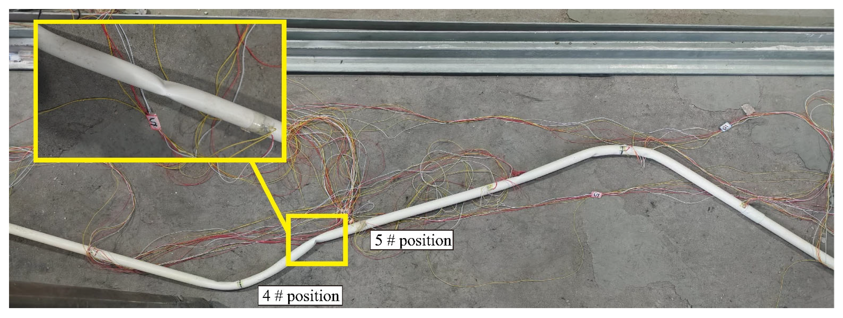
The gas transmission pipeline passing through the mining area of the Mugua Coal Mine has a diameter of 1000 mm, wall thickness of 20 mm, material density of 7850 kg/m3, an elastic modulus of 207 GPa, Poisson’s ratio of 0.3, and burial depth of approximately 3 m. As a long-distance transportation pipeline, the conveying pressure is determined as 10 MPa based on relevant sources [34]. The pipeline section spans from Stake SC051 to Stake SC075, covering a length of about 3000 m, and exhibits both crossing and parallel spatial relationships with the coal mining face. The underlying coal seam has an average thickness of 5.85 m, with a surface soil layer ranging from 40 to 90 m in thickness and an overlying mountain cover of 120–150 m. The characteristics of the pipelines in this area are as follows: the plane is mainly composed of curves, and the longitudinal terrain fluctuates frequently, which often constitutes a spatial curve. Figure 1 illustrates the observed damage to surface soils and the gas pipeline within the subsidence-affected goaf area.
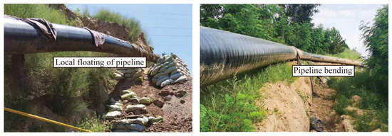
Figure 1.
Failure characteristics of gas pipeline in mountainous areas.
3. Similar Simulation Test on the Influence of Mountain Terrain Pipeline Under the Influence of Mining
3.1. Test Device Design
3.1.1. Calculation of Similar Simulation Parameters
To design a pipe–soil interaction test setup, the stratigraphic thickness of the coal mining area was proportionally scaled to determine the geometric similarity constants for the scaled model. Considering the pipeline traversing the subsidence basin and applying Saint Venant’s Principle, the disturbances to subsidence-induced stress caused by cross-section dimensions are negligible. Consequently, diameter effects are disregarded, while scaling focuses on length-to-height ratios of the model. Based on the research by Wang et al. [26] and the study background, the geometric similarity constants and mechanical property similarity constants between the prototype and the model were determined, as shown in Table 2.
Table 2.
Parameters of physical similarity simulation experiment.
3.1.2. Similar Simulation Pipeline Selection
The test pipe is made of PVC material, with a diameter of 50 mm and a wall thickness of 1.5 mm. The physical and mechanical properties of the PVC pipe are shown in Table 3.
Table 3.
Physical and mechanical parameters of pipeline.
Gas pipeline mechanical responses and failure modes exhibit significant terrain-dependent variations. In complex mountainous regions, pipelines encounter heightened mechanical complexity. To analyze deformation mechanisms under such conditions, this study employs curved PVC pipes, bent at 30°, to replicate typical engineering configurations simulating pipeline segments across distinct topographic zones. This approach enables systematic examination of stress distribution and deformation thresholds at slope transitions and valley interfaces.
3.2. Similar Test Bench and Monitoring System Layout
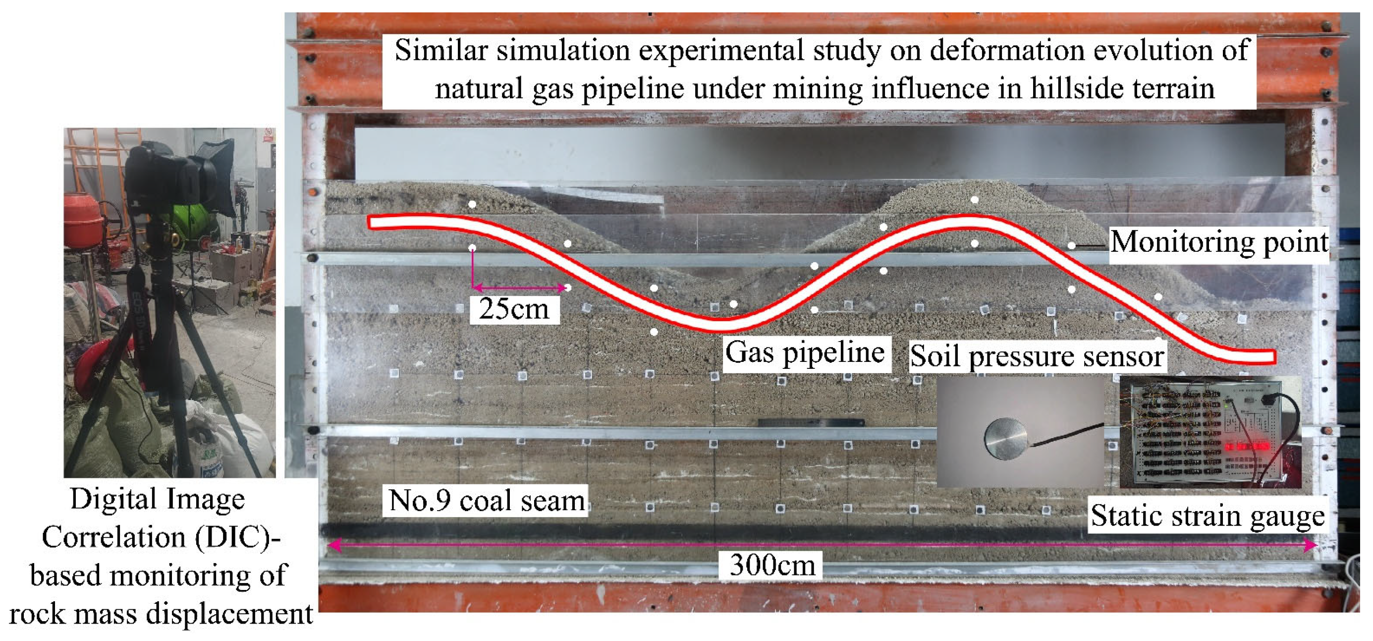
To investigate the impact of subsidence basins in mountainous terrain on gas pipeline deformation, a similarity simulation experiment was designed based on the geological conditions of the mining area where the pipeline is located. This experiment aims to simulate the deformation evolution of gas pipelines under mining-induced disturbances in slope terrain. The experimental system comprises three main components: a 3 m × 0.2 m × 1.4 m planar model frame serving as the simulation platform, a photographic monitoring system (including digital cameras, remote-controlled shooting systems, and fill lights) to visually document deformation processes, and a stress–strain acquisition system equipped with static resistance strain gauges, soil pressure cells, and strain gage rosettes to measure mechanical responses of the pipeline and surrounding soil. This setup enables detailed analysis of pipeline stress redistribution and failure mechanisms under dynamic subsidence conditions.
As shown in Figure 2, soil pressure sensors were employed to monitor the stress in the soil surrounding the pipeline. During soil pressure testing, these sensors must not make direct contact with the pipeline surface. To effectively distinguish stress variations in the soil adjacent to the pipeline, sensors were positioned 3 cm above and 3 cm below the model pipeline. To ensure comprehensive coverage of critical pipeline zones, the sensors were laterally spaced at 25 cm intervals. Collectively, 18 soil pressure sensors were deployed along the measurement line to monitor stress data in the pipeline -surrounding soil during subsidence development. A digital photogrammetric monitoring system was utilized to track settlement values of the soil surrounding the pipeline at various subsidence stages.
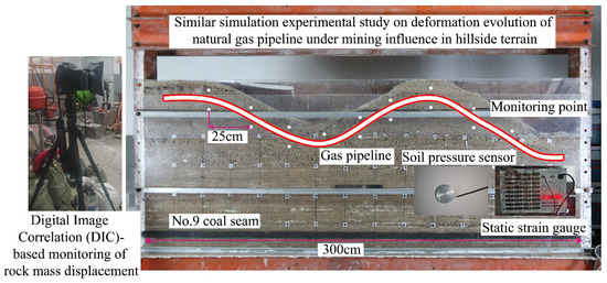
Figure 2.
Layout of test bed and soil stress monitoring system.
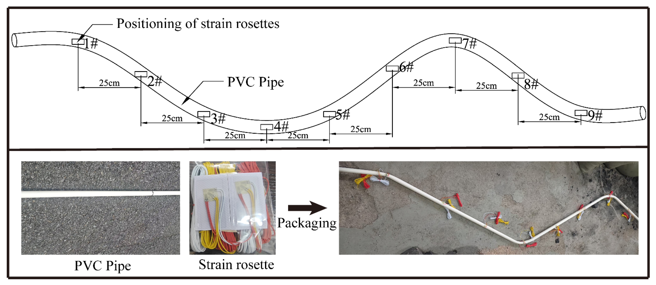
As shown in Figure 3, pipeline strain monitoring was conducted using strain gage rosettes. Prior to the test, the PVC pipeline was pre-bent, and strain gauges were installed at 25 cm intervals along the horizontal axis of the curved section, corresponding to the designated strain measurement points. The strain gage rosettes were sequentially labeled as Points from 1 # to 9 #, aligned with the positions of the soil pressure cells, to ensure spatial consistency in data acquisition. Prior to installation, strain gauges must maintain structural integrity and undergo bridge balancing and zero calibration to ensure the accuracy and integrity of the strain data during the measurement process.
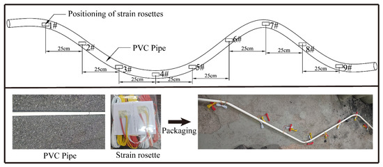
Figure 3.
Layout of pipeline strain monitoring system.
3.3. Observation of Rock Subsidence in the Process of Subsidence Development
Image processing software was utilized to analyze images captured during the subsidence process. By tracking the coordinate changes in pixels before and after excavation, the movement of rock strata was evaluated. The image analysis covered a pixel range of 5000 × 1600, corresponding to a physical model area of 3 m × 1.2 m, with a 50-pixel spacing between measurement points. This monitoring revealed the progressive movement of rock strata from the coal seam to the surface and the associated surface damage at different stages of working face excavation, as illustrated in Figure 4.
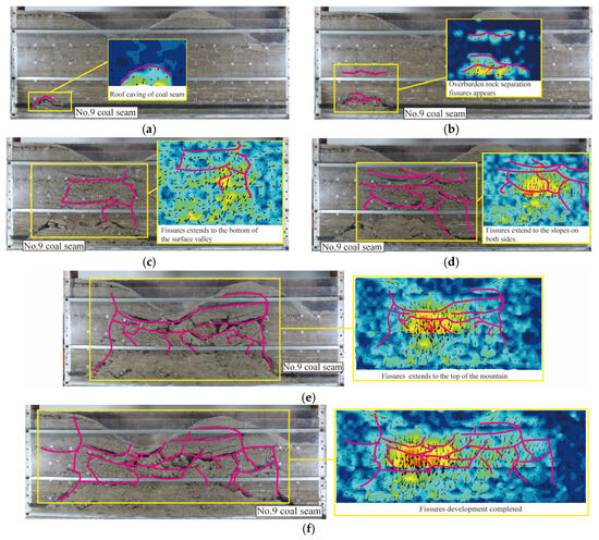
Figure 4.
Displacement changes in rock strata at each stage of mining in the face: (a) working face advancing 50 m; (b) working face advancing 100 m; (c) working face advancing 150 m; (d) working face advancing 200 m; (e) working face advancing 250 m; (f) working face advancing 300 m.
As illustrated in Figure 4, with the progressive advancement of the No. 9 coal seam working face from 50 m to 250 m and its eventual completion, the development of overlying rock fractures and surface subsidence exhibits the following phased evolutionary pattern:
- (1)
- Initial Development Stage: Fractures develop within the interior rock strata. During this phase, the immediate roof becomes unstable and collapses, while horizontal bed-separation fractures emerge in the overlying strata above the roof.
- (2)
- Subsidence Manifestation Stage: Fractures penetrate upward to the valley-bottom at the surface, making subsidence effects apparent. As the working face advances, fractures propagate laterally toward both mountain slopes. Rock strata in the goaf incline toward the subsidence center, with gradual compaction occurring near the mining line. Displacements in the central strata of the subsidence basin increase significantly.
- (3)
- Subsidence Stabilization Stage: The fracture network stabilizes, forming a multidirectional fracture system connecting the surface and goaf. The overall process demonstrates a dynamic coupling characteristic of “vertical penetration-lateral diffusion-compaction equilibrium”.
Overall, as the working face advances, fractures in the rock strata develop rapidly. The undulating mountainous terrain leads to uneven stress distribution in the soil under mining impacts, resulting in an irregular fracture network. Fewer fractures develop in slope areas, as the terrain gradient directs fracture propagation toward valley regions, forming localized fracture concentration zones. Based on fracture patterns observed in similarity simulations, pipelines in mountainous terrain experience significantly different stress conditions compared to those in flat terrains, primarily due to the combined effects of asymmetric subsidence, slope-driven fracture clustering, and dynamic soil–pipe interactions. This highlights the need for terrain to assess pipeline integrity in mining-affected mountainous regions.
3.4. Analysis of Soil Pressure and Pipeline Displacement in the Process of Subsidence
The bending deformation of gas pipelines during the development of a subsidence basin stems from the interaction between the pipeline and the surrounding soil. To analyze the deformation characteristics of gas pipelines under subsidence effects, it is critical to investigate the stress distribution in the soil around the pipeline. In the similarity simulation experiment, soil pressure cells were used to monitor stress variations in the surrounding soil, while strain gage rosettes were employed to measure pipeline deformation. This dual monitoring approach captures the dynamic interplay between soil stress redistribution and pipeline strain localization, providing insights into the mechanical coupling mechanisms driving pipeline bending in subsidence-affected terrains.
3.4.1. Upper Soil Pressure Distribution Along the Gas Pipeline
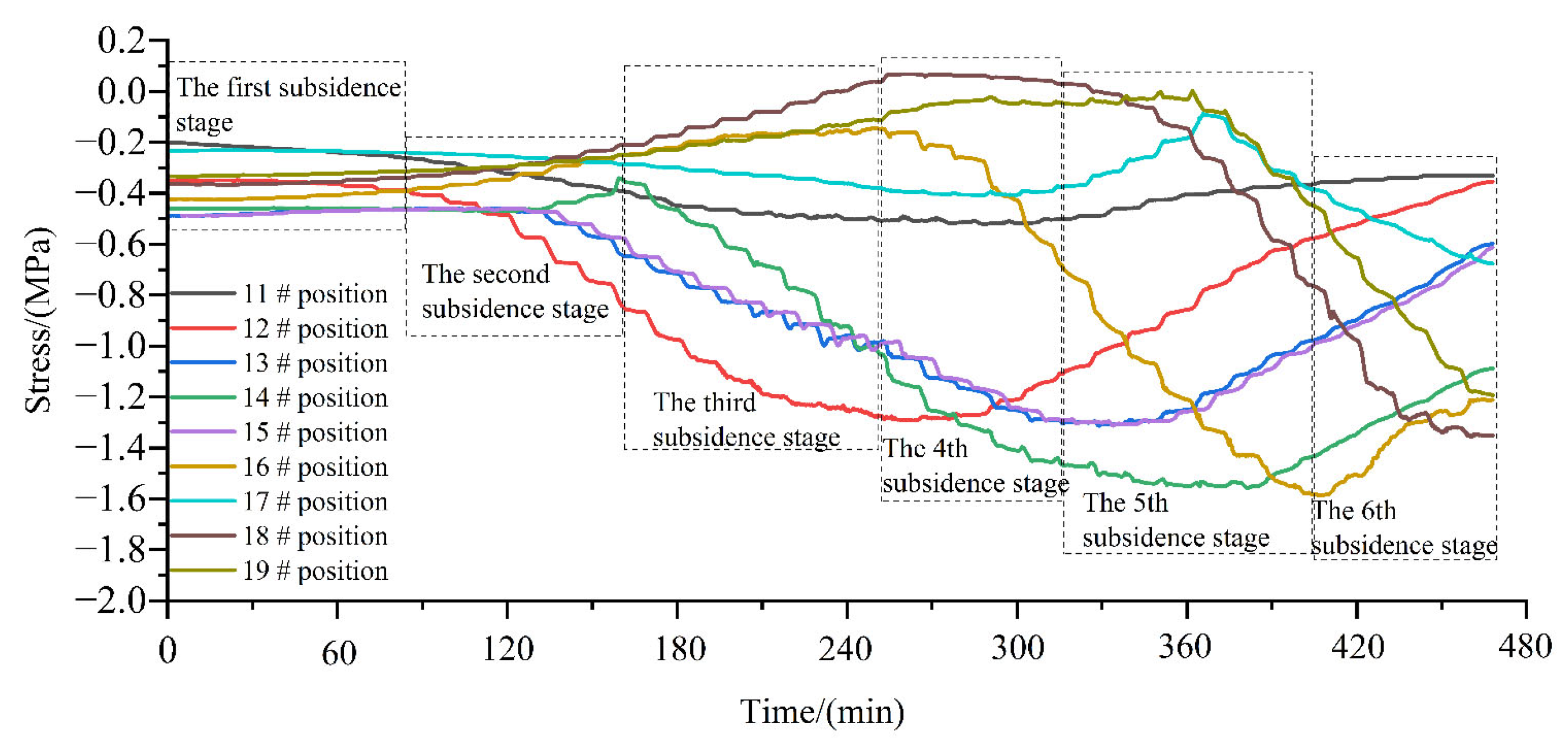
Soil pressure cells were installed above and below the simulated pipeline. The strain gauge system was used to balance and zero the soil pressure cells, ensuring that the monitored stress values directly reflected the actual soil pressure. For systematic analysis, the soil pressure cells above the pipeline were sequentially labeled 11 # to 19 # along the direction from the mining line to the stop line, enabling direct correlation with the corresponding soil pressure cells below the pipeline. This setup facilitated comparative studies of stress asymmetry and load transfer mechanisms between upper and lower soil layers during subsidence progression.
The stress evolution process of the soil measuring points on the upper part of the pipeline is shown in Figure 5. During the subsidence process, the soil pressure of each monitoring point on the upper part of the pipeline has different manifestations in different subsidence stages. Pressure cells 11 # and 17 # are located at the top of the mountain at the edge of the subsidence area. Due to the support of coal pillars and the influence of terrain, the stress changes little during the subsidence process. Pressure cell 14 # is located in the valley of the center of the subsidence area, where the earth pressure subsidence has a great influence. The soil stress continues to increase at the beginning of the second subsidence stage, and the stress reaches the maximum value of 1.6 MPa after reaching the fifth subsidence stage, and then rapidly decays to 1.1 MPa at the sixth subsidence stage. Pressure cells 12 #, 13 #, and 15 # are located in the middle of the mountain slope in the center of the subsidence basin, and the stress change trend is consistent. The stress reaches the maximum value of 1.4 MPa in the middle and late stages of subsidence, and then rapidly decays to about 0.5 MPa. Pressure cells 18 # and 19 # are located at the bottom of the valley at the edge of the subsidence basin. After the first four stages, the stress of the upper soil of the pipeline remains stable, and it begins to increase greatly in the fifth subsidence stage, reaching 1.3 MPa until the mining is completed.
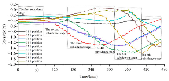
Figure 5.
Stress evolution process of the upper earth pressure box along the pipeline.
3.4.2. Soil Pressure Distribution Along the Lower Part of the Gas Pipeline
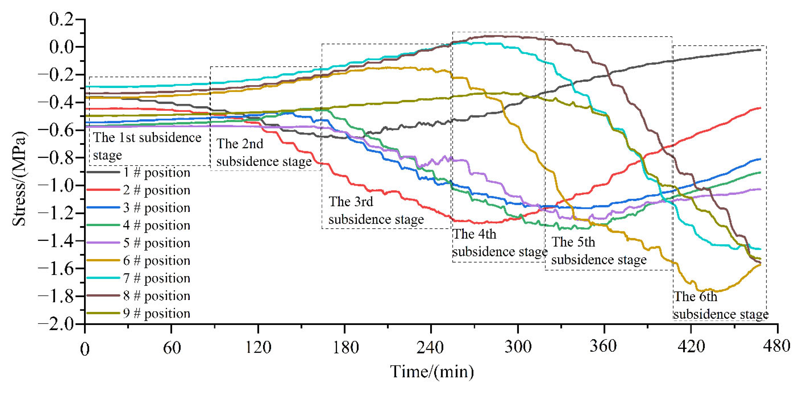
Soil pressure cells numbered 1 # to 9 # were installed in the soil beneath the pipeline to monitor changes in stress distribution along the lower section of the pipeline during the test. As shown in Figure 6, this illustrates the stress evolution process in the soil beneath the pipeline at different stages of subsidence.
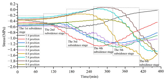
Figure 6.
Stress evolution process of the lower earth pressure box along the pipeline.
As shown in Figure 6, the stress evolution in the soil beneath the pipeline is analyzed as follows: Position 1 #, located at the edge of the subsidence basin with thick overlying strata, exhibits minimal stress variation due to limited subsidence impact. Positions 2 #~5 # show consistent stress trends, remaining stable in the initial mining phase, increasing during the third subsidence stage to a peak of 1.2 MPa, then gradually decreasing and stabilizing around 0.9 MPa. Positions 6 #~7 #, situated on the slope within the basin, experience slight stress reduction in the first three stages, followed by rapid stress escalation from the fourth stage, reaching a maximum of 1.6 MPa by mining completion. Positions 8 # and 9 #, at the mid-slope and valley-bottom of the basin edge, demonstrate aligned stress trends due to slope-to-valley stress transfer, with Position 8 # experiencing lower stress than 9 # during subsidence, though both ultimately attain 1.6 MPa.
In summary, after the subsidence basin stabilizes, the stress distribution and deformation of the gas pipeline exhibit significant terrain dependency: the central valley area forms a maximum compressive stress concentration zone due to vertical compression, accompanied by downward sagging deformation, representing a high-risk compressive failure zone; slope regions experience tensile stress from lateral soil displacement, leading to upward convex deformation and susceptibility to circumferential cracking; transitional zones, subjected to shear–tension coupling effects, emerge as secondary high-risk interfacial failure zones; while residual compressive stress concentrations at local inflection points along the basin edge necessitate vigilance against long-term fatigue damage.
3.4.3. Analysis of Deformation Characteristics of Gas Pipeline
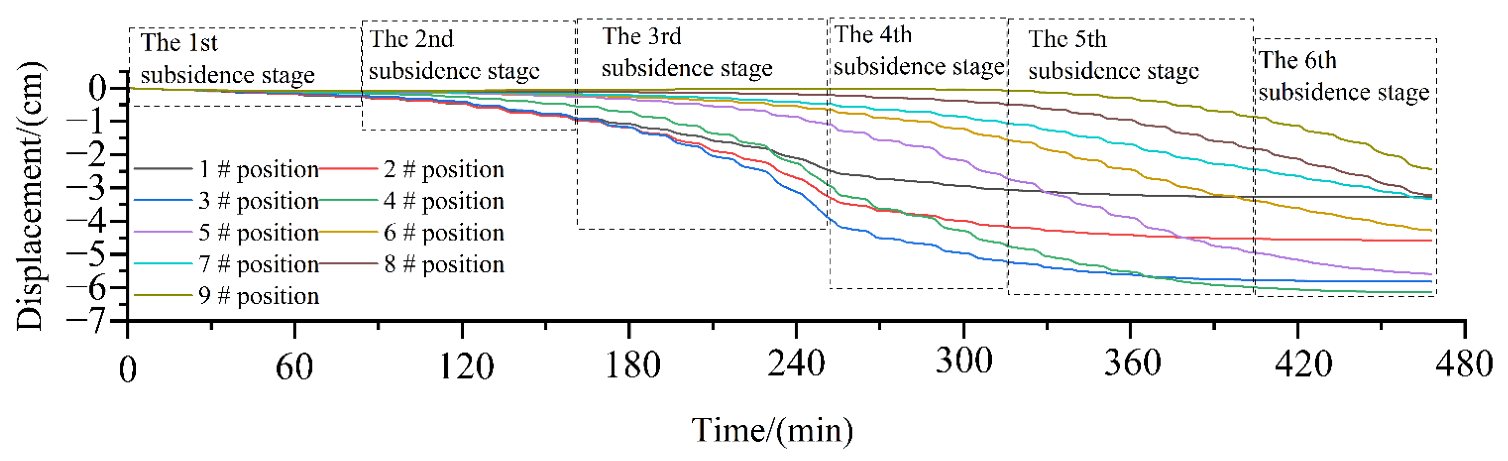
During the subsidence evolution of the soil along the pipeline route, the surrounding soil exerts axial stress on the pipeline, causing bending deformation under subsidence effects. Meanwhile, due to the reduced subsidence impact in partial areas of the mountainous terrain, localized soil provides supporting effects, leading to heterogeneous deformation patterns at different pipeline locations. Displacement values of the gas pipeline at various subsidence stages were collected via strain gauges installed on the PVC pipeline, and the variation patterns of pipeline deformation under subsidence in mountainous terrain were analyzed. The displacement curves are illustrated in Figure 7.
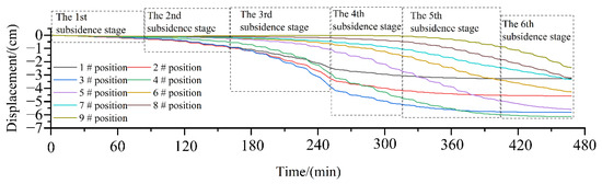
Figure 7.
Evolution process of vertical displacement in the middle of the pipeline.
As shown in Figure 7, during the development of the subsidence basin along the pipeline route, distinct displacement trends are observed in different topographic zones. The maximum displacement occurs at positions 3 #~5 # within the central valley of the subsidence basin. Specifically, position 4 #, located at the valley-bottom, experiences the highest displacement (6.5 cm) due to increased pressure from the inclined slopes on both sides converging toward the valley. Positions 2 # and 6 #, situated on the valley’s flanking slopes, exhibit a final displacement of 4 cm. The minimal displacement (2 cm) is observed at the right edge of the subsidence basin, attributed to reduced subsidence in the later mining stages caused by goaf compaction. Post-test disassembly of the PVC pipeline revealed significant bending deformation between positions 4 # and 5 #, as illustrated in Figure 8.

Figure 8.
Broken pipe in subsidence.
3.5. Force Analysis of Gas Pipeline in Mountainous Terrain
Through the stress analysis of the strain evolution process in the middle of the test pipeline, the stress of the pipeline is shown in Figure 9.
Figure 9.
Force characteristics of gas pipeline.
Mechanical analysis of the gas pipeline within the subsidence basin reveals distinct stress characteristics across the following different zones: the central valley segment experiences downward sagging bending deformation due to a compound compressive stress field from lateral mountain compression and overlying soil pressure, combined with its inherent tensile resistance; the central slope segment is dominated by tensile stress, leading to bidirectional stretching deformation; the edge slope segment undergoes tilted tensile deformation toward the basin center under the coupling of tensile stress and soil self-weight pressure; the edge valley segment bears low compressive stress due to minimal subsidence impact; while slope–valley transitional inflection zones exhibit tension–compression stress boundaries (tension near slopes and compression near valleys). This mechanical zoning law provides a theoretical basis for material selection, deformation-resistant structural design, and targeted protection of critical sections (e.g., valley sag zones and transitional inflection points) in mountainous gas pipelines.
4. Numerical Simulation of Mechanical Response of Gas Pipelines in the Process of Mountain Terrain Subsidence
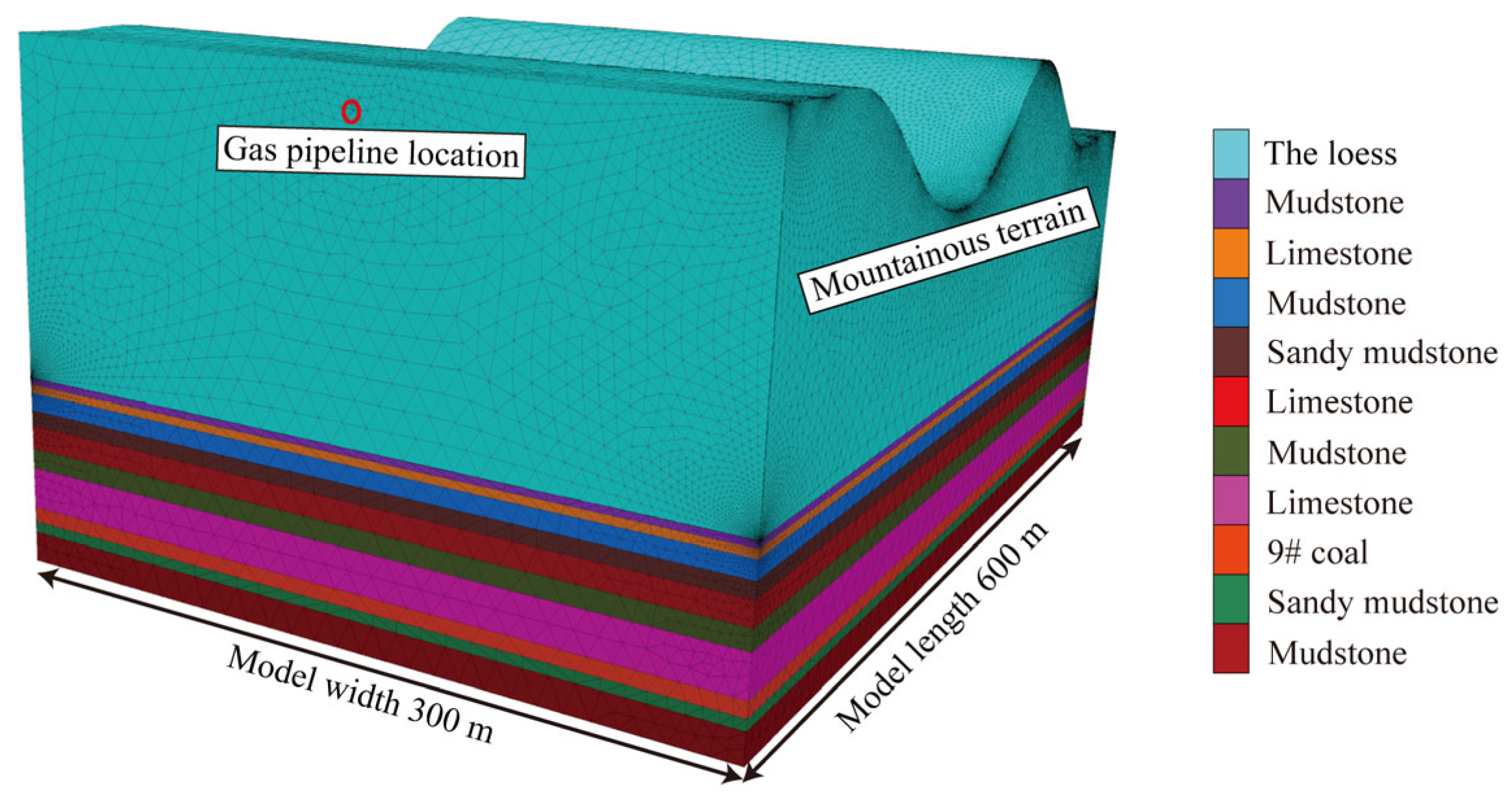
Based on the similarity simulation experiments of pipe–soil interaction under subsidence effects, it is demonstrated that failure locations of gas pipelines in mountainous terrain predominantly occur in the valley regions of collapse-induced subsidence basins. To quantitatively analyze the stress distribution in the pipeline, a surface soil damage and failure model was established using FLAC3D 9.0, incorporating the geological conditions of the Mugua Coal Mine. This model investigates the failure characteristics of surface soil and the stress–deformation behavior of the gas pipeline under mining-induced impacts. The model dimensions are 600 m in length, 300 m in width, with the upper surface simulating mountainous terrain. The mining face length is 200 m, and the total mining distance reaches 500 m. The Mohr–Coulomb constitutive model was adopted to simulate the coal-bearing strata. Horizontal constraints were applied to the four-side boundaries, and vertical displacement was restricted at the lower boundary. Based on the engineering geological conditions, the pipeline burial area primarily consists of loess with no distinct horizontal bedding, exhibiting near-homogeneous properties in its natural state. Consequently, the soil is modeled as an ideal elastoplastic material obeying the Mohr–Coulomb yield criterion [35], with soil stratification effects neglected. The gas pipeline is constructed using liner structures capable of absorbing uneven soil deformations, thereby reducing sensitivity to soil model accuracy. The overall configuration of the model is illustrated in Figure 10.

Figure 10.
Numerical model of pipeline in mountainous terrain.
4.1. Mechanical Response Analysis of Gas Pipeline Under Mining Influence
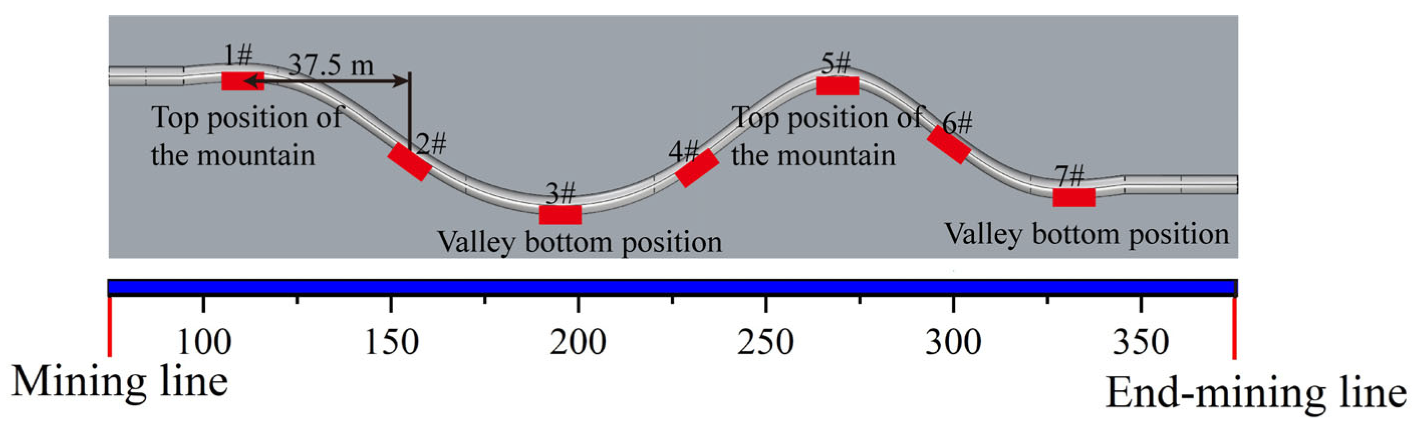
In the model, the FISH scripting language was employed to extract stresses at key nodes of the gas pipeline after each excavation stage. The position of the key nodes is shown on Figure 11. Each node monitors the stress at the bottom of the pipeline, and its horizontal spacing is 37.5 m.
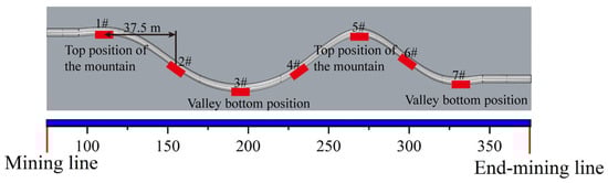
Figure 11.
Location distribution of key nodes.
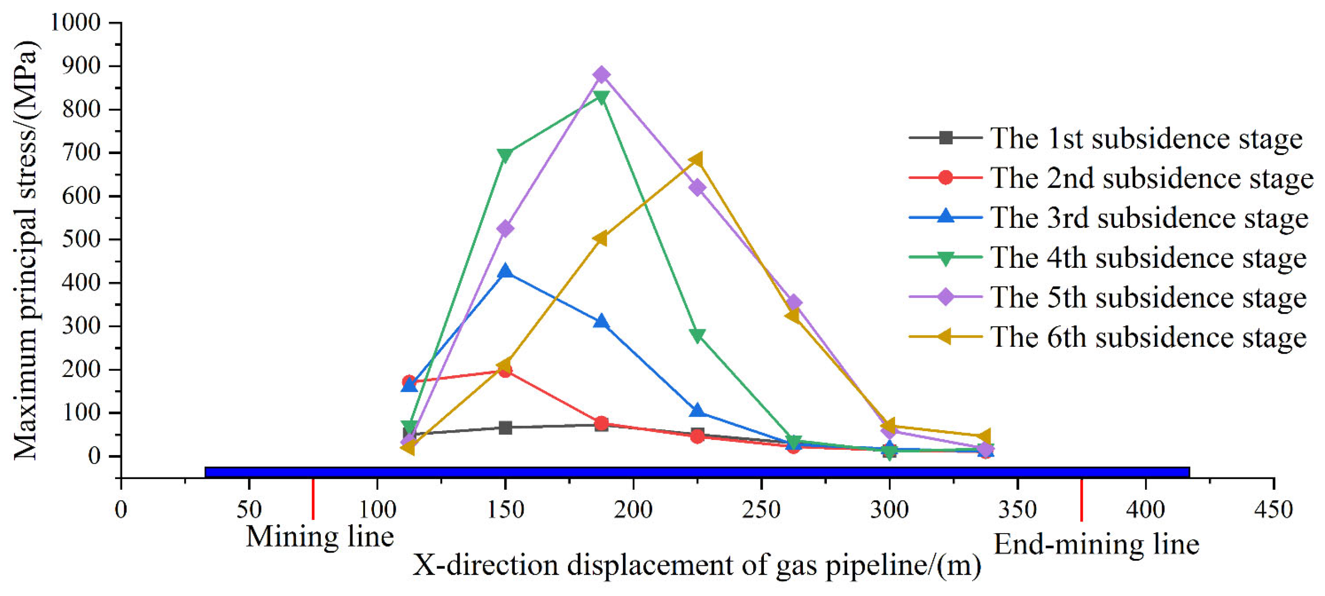
The stress characteristics of the pipeline during the advancement of the mining face were analyzed, revealing the mechanical response patterns of the pipeline under progressive mining. The calculated maximum principal stress of the pipeline during the development of the subsidence basin is illustrated in Figure 12.
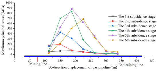
Figure 12.
The maximum principal stress evolution of pipeline in each subsidence stage.
It can be seen in Figure 12 that there is no obvious stress change in the gas pipeline during the first subsidence stage. The stress concentration phenomenon appeared in the second subsidence stage, and the stress of the monitoring points at the left mountain top (1 #) and the slope position (2 #) increased to 150 MPa. After reaching the third subsidence stage, the stress concentration range of the gas pipeline began to extend, and the stress of the monitoring point at the top of the left mountain remained unchanged. The stress of the monitoring points in the valley (3 #) and on both sides of the mountain (2 #, 4 #) increased, and the stress value of the 2 # monitoring point was the largest, reaching 400 MPa. In the fourth subsidence stage, the range of gas pipeline affected by subsidence did not increase, the stress of 1 # monitoring point decreased, the stress of 2 #~4 # monitoring point continued to increase, the position of the maximum stress point became the left valley, and the stress reached 870 MPa. In the fifth subsidence stage, the range of gas pipeline affected by subsidence increases to the right valley position, the stress of 2 # monitoring point decreases, the stress of 3 # monitoring point is still the maximum value, and the stress of 3 # monitoring point increases slightly to 920 MPa, and the stress of 4 # and 5 # monitoring points increases significantly. In the final sixth subsidence stage, the stress of the whole gas pipeline changed, and the maximum stress position moved to the right hillside. The stress value was 700 MPa, and the stress of the whole gas pipeline decreased.
In summary, the stress concentration phenomenon in pipelines under mountainous terrain exhibits the following distinct dynamic migration characteristics: during the initial stage, stress concentrates at the pipeline front; it shifts toward the mid-section in the intermediate phase and ultimately extends to the central region in the final stage. The maximum stress value of the gas pipeline follows an initial increase followed by a decrease, peaking at 920 MPa during Stage 5 of subsidence. In Stage 6, the overall stress decreases due to stress redistribution caused by plastic deformation or localized failure of the pipeline.
4.2. The Stress Distribution of Gas Pipeline Under the Influence of Mining
During the surface soil subsidence process, certain areas of the soil undergo continuous damage, and the gas pipeline laid in these regions is persistently affected by the degradation of the surrounding soil. To study the stress distribution state of the gas pipeline within the soil, Figure 13 illustrates the simulated pipe–soil deformation and pipeline stress distribution after the completion of the numerical model.
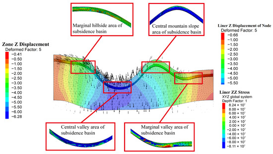
Figure 13.
Mountain terrain pipe–soil deformation and pipeline stress distribution map.
As illustrated in Figure 13, after the subsidence basin stabilizes, the stress distribution and deformation characteristics of the gas pipeline exhibit the following significant spatial heterogeneity: the central valley area forms a maximum compressive stress concentration zone due to vertical soil pressure and separation of the soil beneath the pipeline, resulting in downward sagging deformation of 5.5 m, identified as a high-risk compression failure zone; slope regions experience upward convex deformation dominated by tensile stress induced by lateral soil displacement, which predisposes the pipeline to tensile cracking; transitional zones between valleys and slopes, subjected to shear–tension/compression coupling effects, become secondary high-risk failure zones; while the basin edges exhibit lower overall stress, localized compressive stress concentrations and sagging deformation persist at valley inflection points. Overall, priority should be given to compressive reinforcement and deformation monitoring in stress-concentrated critical zones (valley–bottoms and transitional segments), whereas tensile-resistant measures and crack detection should be emphasized in tensile-dominated slope regions.
As shown in Figure 14, comparative analysis of the deformation results from similarity simulations and numerical modeling reveals remarkable consistency in the following displacement distribution patterns and failure characteristics: both methods demonstrate concentrated displacement extremes at the valley base of the subsidence basin center, progressively decreasing toward adjacent slopes with identical spatial distribution patterns. Consistent deformation zoning features are observed, with concentric elliptical settlement bands in valley regions and strip-shaped displacement mutation boundaries on slopes. This analysis confirms the reliability of using combined similarity experiments and numerical simulations to investigate pipeline bending deformation mechanisms in mountainous terrain.
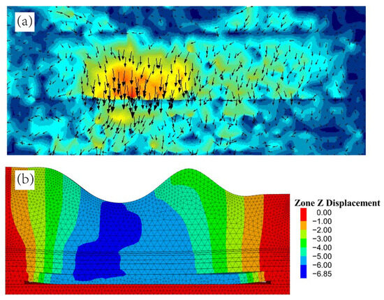
Figure 14.
Comparison of the deformation results between the similar test and numerical simulation. (a) similar simulation test; (b) numerical simulation.
5. Discussion
The findings of this study provide critical insights into the deformation characteristics and mechanical responses of gas pipelines in mountainous goaf areas, enhancing the understanding of pipeline safety under complex geological conditions. The combined approach of similarity simulation and numerical simulation effectively captured the dynamic interactions between pipeline deformation, soil–pipe settlement, and stress redistribution, establishing a framework for analyzing such geotechnical engineering challenges.
Mountainous pipelines develop the following terrain-specific stress-deformation responses: central valleys exhibit concentrated compression from topographic load transfer and adjacent slope actions, causing maximum downward deflection; slopes display tensile dominance consistent with differential subsidence. Valley–slope transitions form secondary high-risk zones with shear–tension coupling—mechanistically corroborating Kouretzis et al. [21]—due to stress redistribution and amplified lateral soil transfer inducing tensile-shear deformation.
The stress redistribution phenomenon observed in this study during subsidence: initial front-end stress concentration, subsequent mid-pipe stress migration, and eventual stress reduction, aligns with the dynamic stress evolution reported by Huang et al. [20] in analogous subsidence scenarios. Simultaneously, our findings emphasize terrain-driven mechanisms absent in plain-based studies. For instance, the irregular fracture networks in mountainous regions, shaped by slope-to-valley stress transfer, starkly contrast with the uniform fracture propagation observed in plains [14]. Additionally, compared to subsidence basin development in flat terrain, mountainous topography amplifies the spatial variation in overburden thickness, resulting in full-cycle delays in stress transfer, fracture propagation, and subsidence stabilization. The comparative results are presented in Table 4. The delayed stress response in thick-covered slope areas aligns with findings by Xu [9] on time-dependent settlement effects, though this concept is extended here to spatially variable terrain conditions.
Table 4.
Comparative results of surface thickness differences in different terrains.
The study identifies high-risk zones requiring engineering protection for pipeline installation in mined-out mountainous terrain, specifically the central valley and transition areas. For the central valley zone, high-strength steel pipelines can enhance compressive resistance while hydraulic self-adjusting support systems installed beneath the pipeline reduce subsidence impacts. Transition zones should utilize steel pipes with superior tensile properties, incorporating flexible joints to absorb shear deformation and installing anti-slide piles in surrounding soil to restrain lateral displacement. Adopting the segmentation strategy proposed by Jiang et al. [23] for goaf areas, pipelines in high-risk zones are divided into independent segments to mitigate post-failure repair scope.
Although this study proposes safety protection measures for pipelines in mountainous terrain, certain limitations warrant attention. The simplified homogeneous soil model used in simulations may underestimate heterogeneous soil–pipe interactions, particularly in layered strata with varying lithologies. This study simultaneously overlooks the bedding effects of rock strata, resulting in significant discrepancies that introduce errors in stress transfer within actual slope–valley transition zones; moreover, it overestimates the bearing capacity of valley–bottom soils, causing delayed pipe bending during experimentation. Additionally, factors such as seismic activity or thermal cycling, which could exacerbate long-term fatigue, were not considered. Future studies should integrate multi-physics coupling models to address these complexities. Long-term field monitoring using distributed fiber optic sensors could validate and refine the proposed mechanisms, while advanced materials (e.g., carbon–fiber composites) should be explored to enhance deformation tolerance in critical zones.
By elucidating the interactions between gas pipelines and surrounding soil during subsidence in mountainous terrain, this study lays the foundation for optimizing gas pipeline safety in topographically complex regions. The terrain-dependent stress transfer mechanisms and corresponding protection strategies provide engineers with actionable guidelines, effectively bridging the gap between theoretical models and field applications.
6. Conclusions
This study investigates gas pipeline safety mechanisms in mountainous terrain under coupled mining subsidence-topographic effects through comparative similarity–numerical modeling. Key conclusions indicate:
- (1)
- Through integrated similarity simulation and finite element modeling, this study elucidates the mechanical–deformation behavior of gas pipelines in mountainous terrain under subsidence. Topographic stress convergence from flanking slopes generates maximum compressive stress concentration in the central subsidence basin valley, inducing significant downward pipeline sagging deformation. Slope regions exhibit tensile-dominated stress regimes due to lateral soil displacement, producing upward convex deformation. Transition zones develop critical shear–tension coupled stress distributions, identified as high-risk areas. The research confirms synergistic evolution between terrain gradient and strata fracture development, with valley stress concentration notably exceeding slope manifestations.
- (2)
- By establishing a pipe–soil interaction model, this study clarifies the deformation and stress mechanisms of pipelines in mountainous terrain: the coordinated deformation stage exhibits synchronous pipe–soil displacement, while the non-coordinated stage triggers stress redistribution due to bed-separation effects; numerical simulations indicate the pipeline’s peak stress reaches 920 MPa during mid-late subsidence—exceeding the material’s yield limit—with subsequent stress reduction occurring through localized failure, thereby validating experimental observations of valley-bottom depression deformation in similarity simulations.
- (3)
- Analysis of pipeline stress states during subsidence basin development reveals regionally differentiated mechanical characteristics: the central valley segment undergoes downward depression under composite compressive stresses, slope segments experience biaxial or inclined tensile dominance, marginal valley zones exhibit reduced compression, while slope–valley transitions demonstrate tension–compression boundary effects. These findings establish theoretical foundations for mountainous gas pipeline safety protection. Implementation strategies include compressively reinforced structures with continuous strain monitoring in valley zones; tensile-resistant configurations employing segmented construction on slopes; and prioritized shear–failure prevention in transition sections.
Author Contributions
Conceptualization, G.Z.; formal analysis, H.L.; funding acquisition, G.Z.; methodology, J.L. and H.L.; project administration, G.Z.; resources, G.Z.; software, J.L.; visualization, H.L.; writing—original draft, J.L.; writing—review and editing, J.L. All authors have read and agreed to the published version of the manuscript.
Funding
The work is funded by the Basic Research Foundation of Shanxi Province, China (Grant No. 202303021221007) and National Natural Science Foundation of China (Grant No. U22A20167).
Data Availability Statement
The original contributions presented in the study are included in the article, further inquiries can be directed at the corresponding author.
Conflicts of Interest
The authors declare no conflicts of interest.
References
- Ye, H. Risk Factors and Management Methods for the Safe Operation of Natural Gas Transmission Pipeline. Chem. Eng. Manag. 2022, 20, 79–81. [Google Scholar] [CrossRef]
- He, L.; Wang, W. Research Status and Development Trends of Natural Gas Pipelines. Chem. Eng. Equip. 2023, 7, 210–212. [Google Scholar] [CrossRef]
- Liang, X.; Liang, W.; Deng, K.; Sun, Z. Simulation on the stress and strain of suspended gas pipelines in goafs. Oil Gas Storage Transp. 2019, 38, 145–150. [Google Scholar]
- Ran, L.; Wang, X. Study of Effective Factors for Safety Assessment of Buried Suspending Piping. Process Equip. Pip. 2016, 53, 81–86. [Google Scholar] [CrossRef]
- Zhu, Q.; Ji, W.; Sun, X. Subsidence Numerical Simulation for Loess Overlying Rock Mining Area with Thin Buried Depth and Large Mining Height. Saf. Coal Mines 2016, 47, 230–233. [Google Scholar] [CrossRef]
- Yu, J.; Jing, H.; Liu, X.; Shan, C. Mechanism of Surface Subsidence Propagation Based on Structural Instability Characteristics of Combined Rock Strata. J. Northeast. Univ. 2022, 43, 559–566. [Google Scholar] [CrossRef]
- Huang, X.; Li, X.; Li, H.; Duan, S.; Yang, Y.; Du, H.; Xiao, W. Study on the Movement of Overlying Rock Strata and Surface Movement in Mine Goaf under Different Treatment Methods Based on PS-InSAR Technology. Appl. Sci. 2024, 14, 2651. [Google Scholar] [CrossRef]
- Can, E.; Mekik, Ç.; Kuşcu, Ş.; Akçın, H. Monitoring deformations on engineering structures in Kozlu Hard Coal Basin. Nat. Hazards 2013, 65, 2311–2330. [Google Scholar] [CrossRef]
- Xu, L.; Sun, Z.; Liu, X.; Zhang, K.; Cao, Z. Dynamic prediction of surface subsidence at any point based on Boltzmann time function model. J. China Coal Soc. 2025, 50, 715–731. [Google Scholar] [CrossRef]
- Tang, F.; Gao, J.; Xue, J.; Zhu, C.; Zhou, D.; Lin, X. Research on dynamic subsidence prediction model of surface in western mining area based on GNSS time series observation data. Coal Sci. Technol. 2024, 1–11. Available online: http://kns.cnki.net/kcms/detail/11.2402.TD.20241016.1701.005.html (accessed on 26 May 2025).
- Babaryka, A.; Benndorf, J. New Subsidence Prediction Method Incorporating Asymmetry and Shape Flexibility: A Study Case of Salt Caverns in North Germany. Rock Mech. Rock Eng. 2025. [Google Scholar] [CrossRef]
- Ghabraie, B.; Ren, G.; Barbato, J.; Smith, J.V. A predictive methodology for multi-seam mining induced subsidence. Int. J. Rock Mech. Min. Sci. 2017, 93, 280–294. [Google Scholar] [CrossRef]
- Deck, O.; Baroudi, H.; Hosni, A.; Gueniffey, Y. A time dependency prediction of the number of mining subsidence events over a large mining field with uncertainties considerations. Int. J. Rock Mech. Min. Sci. 2018, 105, 62–72. [Google Scholar] [CrossRef]
- Zhu, M.; Yu, X.; Tan, H.; Yuan, J.; Chen, K.; Xie, S.; Han, Y.; Long, W. High-precision monitoring and prediction of mining area surface subsidence using SBAS-InSAR and CNN-BiGRU-attention model. Sci. Rep. 2024, 14, 28968. [Google Scholar] [CrossRef]
- Chi, S.; Wang, L.; Yu, X.; Lv, W.; Fang, X. Research on dynamic prediction model of surface subsidence in mining areas with thick unconsolidated layers. Energy Explor. Exploit. 2021, 39, 927–943. [Google Scholar] [CrossRef]
- Zhao, B.; Wu, G.; Li, J.; Wu, Q.; Deng, M. Spatio-Temporal Heterogeneous Ensemble Learning Method for Predicting Land Subsidence. Appl. Sci. 2024, 14, 8330. [Google Scholar] [CrossRef]
- Ren, J.; Wang, W.; Dong, M.; Gao, S. Analysis of deformation and echanical characteristics of buried pipelines in mining subsidence areas. China Saf. Sci. J. 2020, 30, 82–89. [Google Scholar] [CrossRef]
- Wang, X.; Suai, J.; Zhang, J. Mechanical response analysis of buried pipeline crossing mining subsidence area. Rock Soil Mech. 2011, 32, 3373–3378+3386. [Google Scholar] [CrossRef]
- Dong, S.; Samsonov, S.; Yin, H.; Yao, P.; Xu, C. Spatio-temporal analysis of ground subsidence due to underground coal mining in Huainan coalfield, China. Environ. Earth Sci. 2015, 73, 5523–5534. [Google Scholar] [CrossRef]
- Huang, Z.; Yu, X.; Lv, Z.; Chen, C.; Shuai, J.; Li, Y.; Liu, Q. Mechanical response analysis of pipeline under settlement based on pipe-soil interaction model. Appl. Ocean Res. 2024, 151, 104162. [Google Scholar] [CrossRef]
- Kouretzis, G.P.; Karamitros, D.K.; Sloan, S.W. Analysis of buried pipelines subjected to ground surface settlement and heave. Can. Geotech. J. 2015, 52, 1058–1071. [Google Scholar] [CrossRef]
- Gao, N.; Zhang, H.; Liu, G.; Chen, P.; Shi, N.; Liu, X. Calculation model for strain of buried pipeline under the action of continuous surface displacement. Oil Gas Storage Transp. 2021, 40, 809–815. [Google Scholar] [CrossRef]
- Jiang, H.; Wang, H.; Xu, T. Analysis on deformation and stress of buried gas pipeline in mined-out subsidence area. J. Saf. Sci. Technol. 2016, 12, 45–51. [Google Scholar] [CrossRef]
- Liu, P.; Zhang, Y.; Li, Y.; Fan, J.; Wang, W.; Hu, Q.; Huang, W. Pipe-soil interaction during continuous settlement. Oil Gas Storage Transp. 2024, 43, 332–341. [Google Scholar] [CrossRef]
- Zhou, M.; Du, Y.; Wang, F.; You, Q.; Dong, D. Physical modeling of mechanical responses of HDPE pipes and subsurface settlement caused by land subsidence. Chin. J. Geotech. Eng. 2016, 38, 253–262. [Google Scholar] [CrossRef]
- Wang, W.; Ren, J.; Dong, M.; Zhang, S.; Sun, H. A simulation experimental study on deformation evolution of natural gas pipeline under mining influence. J. Min. Saf. Eng. 2020, 37, 777–787. [Google Scholar] [CrossRef]
- Du, F.; Li, R.; Wang, D.; Ren, S.; Sun, X.; Wu, M.; Xie, F. Optimization Study on Treatment Method of Natural Gas Pipeline Excavation Trench in Goaf. Coal Technol. 2024, 43, 185–191. [Google Scholar] [CrossRef]
- Xu, P. Study on the Buried Pipeline-Soil Interaction and Its Mechanical Response by Mining Subsidence. Ph.D. Thesis, China University of Mining and Technology, Xuzhou, China, 2015. [Google Scholar]
- Cucuzza, R.; Devillanova, G.; Aloisio, A.; Rosso, M.M.; Marano, G.C. Analytical solutions for piles’ lateral deformations: The nonlinear stiffness case. Int. J. Mech. Sci. 2022, 229, 107505. [Google Scholar] [CrossRef]
- Jamie, J. Static and Dynamic Analysis of Piles in Inhomogeneous Soil. Ph.D. Thesis, University of Bristol, Bristol, UK, 2022. [Google Scholar]
- Karatzia, X.; Mylonakis, G. Horizontal Stiffness and Damping of Piles in Inhomogeneous Soil. J. Geotech. Geoenviron. Eng. 2017, 143, 04016113. [Google Scholar] [CrossRef]
- Dutta, S.; Hawlader, B.; Phillips, R. Finite element modeling of partially embedded pipelines in clay seabed using Coupled Eulerian–Lagrangian method. Can. Geotech. J. 2015, 52, 58–72. [Google Scholar] [CrossRef]
- Bazaluk, O.; Kuchyn, O.; Saik, P.; Soltabayeva, S.; Brui, H.; Lozynskyi, V.; Cherniaiev, O. Impact of ground surface subsidence caused by underground coal mining on natural gas pipeline. Sci. Rep. 2023, 13, 19327. [Google Scholar] [CrossRef] [PubMed]
- Feng, Y.; Ji, L.; Li, W.; Liu, Y.; Huo, C. Progress and prospects of research and application of X80 pipeline steel and steel pipe in China. Oil Gas Storage Transp. 2020, 39, 612–622. [Google Scholar] [CrossRef]
- Ren, S.; Chen, X.; Ren, Z.; Cheng, P.; Liu, Y. Large-deformation modelling of earthquake-triggered landslides considering non-uniform soils with a stratigraphic dip. Comput. Geotech. 2023, 159, 105492. [Google Scholar] [CrossRef]


Disclaimer/Publisher’s Note: The statements, opinions and data contained in all publications are solely those of the individual author(s) and contributor(s) and not of MDPI and/or the editor(s). MDPI and/or the editor(s) disclaim responsibility for any injury to people or property resulting from any ideas, methods, instructions or products referred to in the content. |
© 2025 by the authors. Licensee MDPI, Basel, Switzerland. This article is an open access article distributed under the terms and conditions of the Creative Commons Attribution (CC BY) license (https://creativecommons.org/licenses/by/4.0/).