1. Introduction
An autotransformer represents a specialized category of power transformers distinguished by its singular winding, a portion of which serves as a common element for both the primary (input) and secondary (output) circuits. This shared winding facilitates energy transfer through both electromagnetic induction and direct electrical conduction, setting it apart from traditional two-winding transformers that rely solely on magnetic coupling. The construction typically involves a series winding, connected in series with the input or output, and a common winding, which is shared by both circuits. In some configurations, particularly in high-power applications, a delta-connected stabilizing winding, also known as a tertiary winding, may be included to mitigate harmonic issues and to supply some local needs.
Autotransformers are susceptible to various faults, both internal and external. Internal faults, including winding, core, insulation, and tap changer issues, can cause significant damage if not promptly detected and cleared. This paper addresses turn-to-turn faults explicitly, which present a unique detection problem because they do not significantly alter the overall current balance, making them difficult to identify with standard protection methods.
While overcurrent protection provides a basic defense against short circuits and overloads, it lacks the necessary sensitivity to accurately detect turn-to-turn faults. Therefore, differential current protection is often considered for detecting ground faults and other internal winding faults [
1]. However, applying differential protection to autotransformers presents specific challenges due to their unique winding arrangement. The shared winding complicates the fundamental principle of ampere-turn balance, which is essential for transformer operation and protection. The specific configuration of the differential protection scheme also varies considerably based on such factors as CT placement, the loading condition of the tertiary winding, and the autotransformer’s construction (either a single three-phase bank or three individual single-phase units). Apart from standard differential protection with phase currents, negative-sequence differential protection can also be applied as a solution that is independent of pre-fault loading and offers higher sensitivity [
2,
3].
Other methods for protecting power transformers may be based on the analysis of superimposed positive- and negative-sequence currents [
4] or space-vector quantities [
5]. Some papers suggest applying artificial intelligence (artificial neural networks [
6] or fuzzy logic schemes [
7]) or the PSO technique [
8]. A hybrid detection scheme is introduced in [
9], combining negative-sequence and extended Park vector algorithms. The methods mentioned utilize the same set of input signals and do not guarantee errorless performance under all conditions. Transformer frequency characteristics (fingerprints) [
10] or magnetic flux-based approaches [
11] have also been proposed. Nevertheless, they require a lot of information about detailed transformer parameters and are very complex, making them unsuitable for practical application. Moreover, it is worth noting that none of the schemes mentioned have been tested for TTFs in autotransformers, particularly those with a tertiary delta winding.
In this paper, the operation of the positive- and negative-sequence current differential schemes is compared to the performance of the negative-sequence integral protection, initially developed by the authors for power transformers and described in [
12]. This paper focuses on the analysis and testing of the turn-to-turn fault protection of an autotransformer with a fully loaded tertiary winding. This full-load scenario is realistic, as tertiary windings can supply diverse loads, such as shunt reactors, shunt capacitors, power station auxiliaries, and nearby substation areas.
In subsequent chapters of the paper, the proposed protection scheme is outlined (
Section 2), and the details of the autotransformer model for simulating turn-to-turn faults are described, along with brief validation results (
Section 3). Next, the testing of negative-sequence current integral protection is presented and discussed, with the main focus on the scheme’s sensitivity to internal faults and its security against external short-circuits (
Section 4).
2. Negative-Sequence Current Integral Method for Detection of Turn-to-Turn Faults
The proposed turn-to-turn fault protection algorithm will be presented for a typical autotransformer as follows.
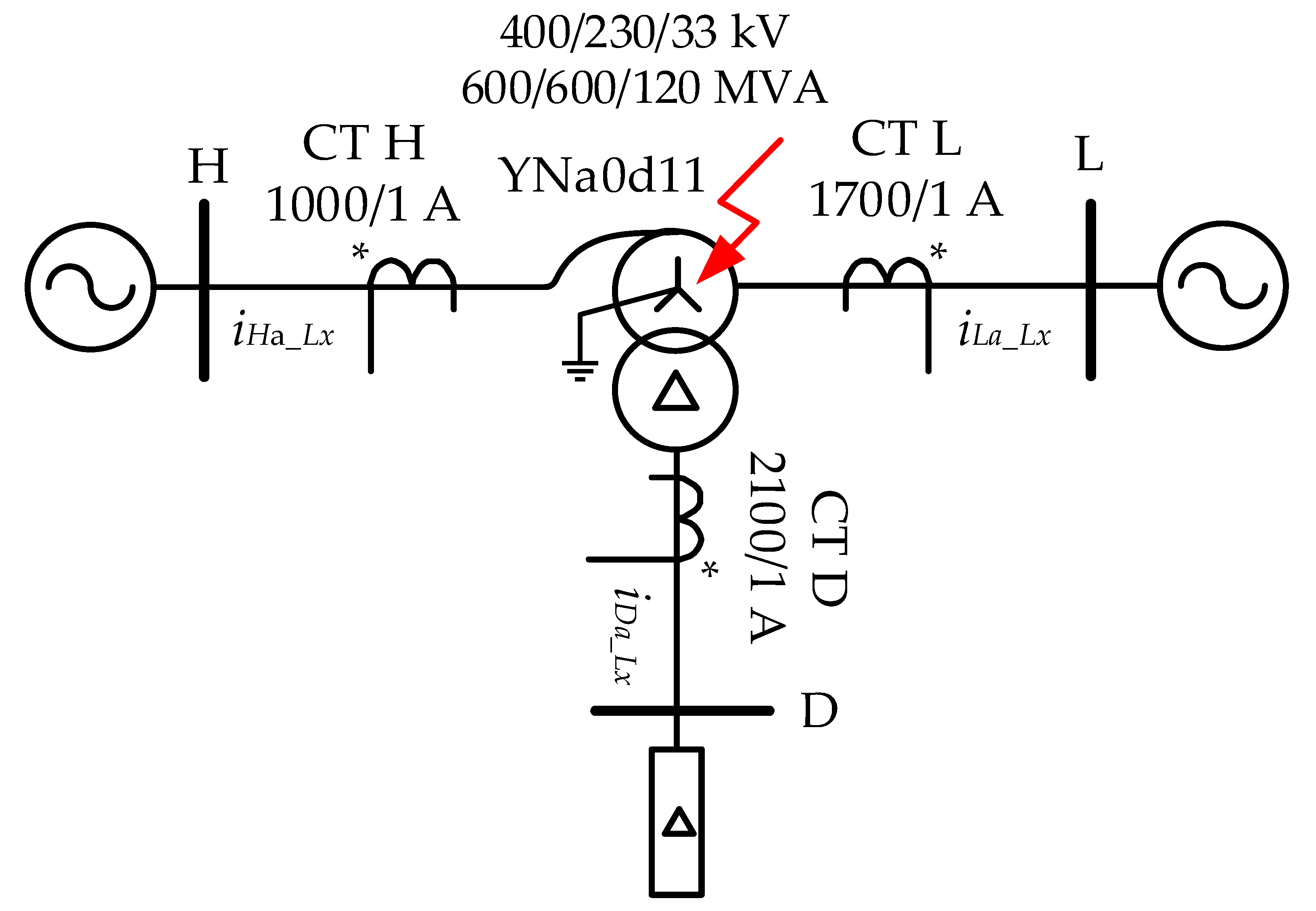
The single-line diagram in
Figure 1 illustrates the YNa0d11 autotransformer under consideration, along with the locations of the current transformers (CTs). This configuration necessitates treating the autotransformer as a three-winding transformer with a Yyd equivalent vector group for current differential protection, requiring current measurements from the high, low, and tertiary windings. A critical aspect is the elimination of zero-sequence currents from both the high-voltage and low-voltage sides, as these currents can circulate within the delta tertiary winding without being detected by the differential relay [
1].
For the subsequent analysis, the terminal currents on each side of the autotransformer (
iH_Lx,
iL_Lx,
iD_Lx) were normalized using the per-unit system, and the current transformer (CT) ratios were also taken into account. Finally, the terminal currents on each side of the autotransformer (
iHa_Lx,
iLa_Lx,
iDa_Lx) expressed in the per-unit system (with CT ratios incorporated) are as follows:
where (for the considered autotransformer unit)
Considering the above, the differential currents are determined by the following:
where:
Lx represents phase
L1…
L3,
iH_Lx represents terminal current at high side,
iL_Lx represents terminal current at low side,
iD_Lx represents terminal current at delta side,
i0H represents zero-sequence current at high side
i0H = (
iH_L1 +
iH_L2 +
iH_L3)/3,
i0L represents zero-sequence current at low side
i0L = (
iL_L1 +
iL_L2 +
iL_L3)/3,
iALx represents
A-side current, and
iBLx represents
B-side current used for further integral method analysis.
The turn-to-turn integral protection based on negative-sequence currents has already been introduced by the authors for a two-winding power transformer, as described in [
12]. It is proposed that the integral
W of the negative-sequence currents at both transformer sides (
A,
B) is calculated as follows:
where
W represents integral quantity and
T1 represents the period of the fundamental harmonic.
The full-cycle numerical integration can be performed with the use of the trapezoidal approximation of the integral as follows:
The negative-sequence terminal currents for Equation (4) are calculated according to the following:
where
represents the orthogonal components of terminal currents at sides
A and
B (
, as marked in Equation (2)),
aR = −0.5,
aI =
.
The orthogonal components of the terminal currents used in Equation (5) may be obtained in any way, e.g., by application of the orthogonal FIR filters.
It can be easily shown that the integral
W is positive for internal faults, while for external disturbances, its value becomes negative, allowing for efficient discrimination between the two cases. In other words, it acts like a directional element, meaning that no additional stabilization is needed for external faults. The proposed criterion operates properly when negative-sequence currents from both transformer sides are higher than zero. Unfortunately, extremely low values of
W are observed, for example, in steady-state conditions, as well as for turn-to-turn faults when the transformer is supplied from one side and unloaded. As a countermeasure, the supplementary Δ criteria are proposed in [
12]:
It may be proved that criteria in Equation (6) become functions of sequence differential currents as follows:
where
Id0 and
Id2 are zero- and negative-sequence differential currents, respectively, and
.
Only two of the Δ quantities from Equation (6), e.g., ΔA and ΔB, must be used to detect a turn-to-turn fault in any of the three phases.
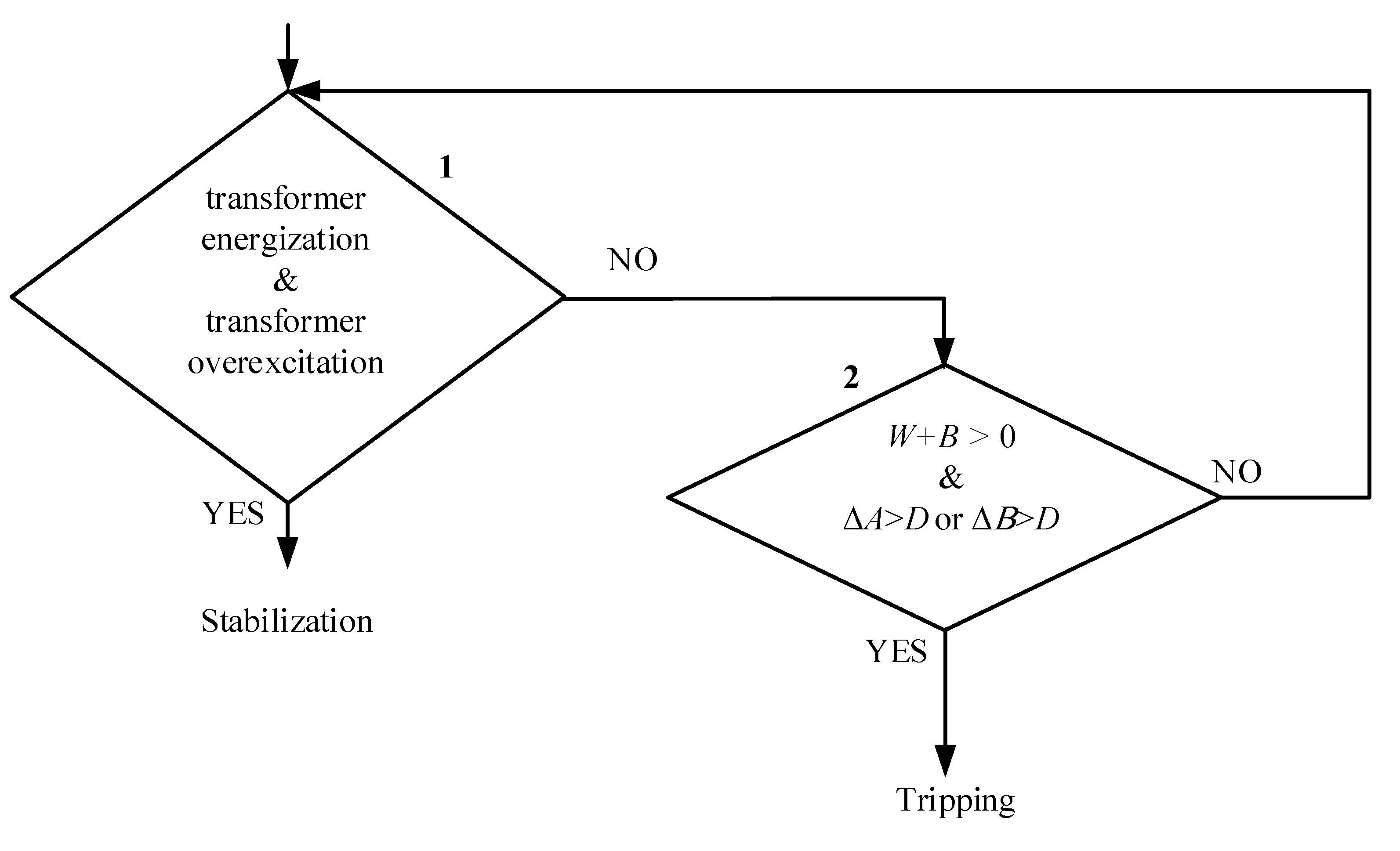
The complete protection also requires evaluation of other stabilization quantities for transformer energization and overexcitation conditions. The logic scheme of the proposed protection is depicted in
Figure 2. Tripping of the protection occurs when the stabilization criteria are negative, the sign of the calculated integral
W is positive (for security reasons, a small constant
B = 0.001 pu is introduced), and the proposed supplementary Δ criteria are high (the threshold
D = 0.01 pu is exceeded).
3. Model of an Autotransformer for Simulation of Turn-to-Turn Faults
It should be noted that the star equivalent circuit is a popular representation of three-winding transformers, including autotransformers (see
Figure 3). To calculate the individual winding impedances (resistance and reactance), short-circuit tests must be carried out between any two of the three windings of the autotransformer, i.e., primary vs. secondary (
ZHL), primary vs. tertiary (
ZHT), and secondary vs. tertiary (
ZLT), with the third winding open. Based on these measured impedances and the star equivalent circuit model, the autotransformer’s individual impedances can be calculated by the following:
with the short-circuit impedances recalculated for accurate modeling of the autotransformer according to [
13]:
where
H,
L, and
T represent high, low, and tertiary voltage terminals, respectively, and
S,
C, and
T represent series, common, and tertiary windings in an autotransformer, respectively, with
,
VS =
VH −
VL,
VC =
VL.
For verification of Equations (8) and (9), it was assumed that the considered autotransformer ratings are 400/230/33 kV, 600/600/120 MVA, YNa0d11,
PcuHL = 666.09 kW,
PcuHT = 148.713 kW,
PcuLT = 157.317 kW,
uk%HL = 11.04%,
uk%HT = 7.97%, and
uk%LT = 5.02%. The autotransformer parameters were calculated, and the results are given in
Table 1. It can be observed that the individual impedances of the three windings computed in this manner can be used for modeling autotransformers with satisfactory results. To confirm this, a short-circuit test was carried out in a MATLAB/Simulink v. 2024b environment. To develop the autotransformer model, a multi-winding transformer from the Simulink library was used.
Figure 4 presents the short-circuit test results for the developed autotransformer model. The obtained results (
Pcu,
uk%) match those specified on the nameplate of the considered autotransformer. Despite receiving the correct results, it can be observed that the reactance of the common winding,
XC, is negative—a typical characteristic of the considered autotransformer model. This does not imply that it represents capacitance but rather is a consequence of the mathematical representation of such an autotransformer. The negative value of
XC is mainly due to the arrangement of the windings and the mutual couplings in the middle winding region [
14,
15].
It can be concluded (based on short-circuit test results) that this autotransformer model can be used for analyzing steady-state conditions as well as internal (at terminal) and external fault cases. However, the proposed protection algorithm should be primarily tested for turn-to-turn short circuits in autotransformers. Therefore, the autotransformer model for simulating turn-to-turn faults should be adequately modified.
Generally, a model for simulating turn-to-turn faults in two-winding transformers can be found in the literature. The first model [
16] utilizes a fictitious winding and an adequately estimated TTF short-circuit impedance. The second one [
17] is based on an extension of the classical Steinmetz equivalent circuit with an additional winding similar to the autotransformer common winding—here, an estimated TTF short-circuit impedance is also required. The third model is based on the branch impedance or admittance matrix of the transformer [
18,
19]. This model is more detailed, and the autotransformer was modeled in ATP-EMTP software (v. 5.6, 2009), with the results presented in [
18]. It can be observed that such a model is complex, as information about the widths of core legs, windings, air gaps, and average winding height is required; however, this information is often unknown. For each turn-to-turn or turn-to-ground fault scenario (varied number of faulted turns, windings), the binary reactances should be calculated, and the leakage admittance matrix should be formulated. Additionally, this model requires the value of
XDNF to be estimated to match the delta current; it means that in one case, the terminal current at the high and low sides is correct. In the second case (for the other value of
XDNF), only the current at the delta side is correct. It can be concluded that modeling turn-to-turn faults in an autotransformer is problematic, and the validation would be complex. Therefore, it was decided to use the faulted autotransformer model based on the duality approach from the RTDS program. The main advantage is that the entire model exists in RTDS (block _rtds_TRF_TDM_FLT MODEL) [
20]. It allows for the simulation of turn-to-turn and ground faults in all windings, requiring only basic parameters (nominal voltages, resistance, and reactance of each winding)—the user does not need to formulate the leakage admittance matrix of the faulted transformer. Duality models are obtained from the geometrical arrangement of windings in the transformer window [
14,
20]. The terminal duality method provides an equivalent circuit for a transformer that is accurate from the terminals and a good representation of physical short-circuit reactances. The complete dual equivalent circuit, including the magnetizing branches and the winding resistances, is shown in
Figure 5. As seen in this model, mutual coupling between
L12 and
L23 was introduced. This proposed circuit matches the terminal leakage measurements and does not provide negative inductances. Below, the analysis of testing results with this model is presented.
Figure 6 illustrates the basic model of a power system with an autotransformer, corresponding to the scheme from
Figure 1, developed in the RTDS environment. It comprises the autotransformer, as well as an equivalent feeding system from both the high and low sides, represented by an electromotive source behind an appropriate impedance dependent on the source short-circuit power. TTFs are simulated in phase L1.
The equivalent power system impedance at the high side (400 kV) is
ZH = 1.576 + j18.688 Ω, while at the low side (230 kV),
ZL = 1.008 + j9.960 Ω. The tertiary delta side was loaded with the nominal power of 120 MVA. Turn-to-turn faults were simulated at common, series, and delta sides via fault resistances of 1 mΩ and 50 mΩ. The number of short-circuited turns was considered to be between 1% and 99%. Initially, a short-circuit test was performed, and the results obtained were close to the rated values (
uk% and
Pcu). Next, turn-to-turn faults were simulated in all three windings (series, common, and delta), and the model’s behavior was verified. Then, phase differential current and negative-sequence differential current protection algorithms were tested. It was assumed that the pickup threshold for phase differential protection is 0.2 pu, while for the negative-sequence differential protection, it is 0.3 pu, as suggested in [
21] and [
3], respectively.
The results obtained for the autotransformer are similar to those for the two-winding transformer and correspond to the theoretical analysis carried out in [
22,
23,
24]. As can be observed from the figures below, the maximum short-circuit reactance occurs when the shorted turn is located at the top or the bottom of the winding. This is justified by the fact that at the ends of the winding, the radial component of the overall leakage flux becomes more prominent than the axial component. Consequently, the smallest fault current is measured at the fault location at the top and bottom of the winding, while the maximum fault current is measured at the fault in the middle (see
Figure 7,
Figure 8 and
Figure 9). In
Figure 10,
Figure 11 and
Figure 12 it can be observed that the amplitude of phase differential currents is about 0.18 pu (for a fault in the series winding), 0.27 pu (for a fault in the common winding), and 0.2 pu (for a fault in the delta winding) for 1% of short-circuited turns and a fault resistance 1 mΩ. At the same time, the amplitude of phase differential currents is about 0.06 pu (for a fault in the series winding), 0.11 pu (for a fault in the common winding), and 0.01 pu (for a fault in the delta winding) for 1% of short-circuited turns and a fault resistance of 50 mΩ. It can be concluded that the standard differential protection may have a problem with detecting short-circuited turns due to a low differential current value. This protection can detect turn-to-turn faults (via 50 mΩ) from 6% of the number of shorted turns in the series winding, from 2% in the common winding, and 7% in the delta winding. Similar results were obtained for the negative-sequence differential current protection.
The autotransformer model for simulating TTFs has been verified and can now be used for testing the negative-sequence current integral method. Some selected testing cases are presented and discussed in the following chapter.
4. Testing of the Negative-Sequence Current Integral Protection
At the beginning, the testing results of the negative-sequence current integral method are presented for turn-to-turn faults in an autotransformer, under the same conditions as those described in
Section 3.
Figure 13,
Figure 14 and
Figure 15 present the results for TTFs in series, common, and delta windings via fault resistances of 1 mΩ and 50 mΩ. The values of integral
W +
B as well as Δ
A and Δ
B criteria are presented as a function of the number of shorted turns. It can be seen that the proposed method can detect all turn-to-turn faults (even 1% of short-circuited turns and fault resistance 50 mΩ) in the series winding of the autotransformer. Both criteria exceed the threshold. The same situation applies to TTFs in the common winding of the autotransformer. The values of
W +
B are above the threshold for all cases, which indicates an internal fault. At the same time, the values Δ
A and Δ
B are only lower than the threshold for 1% of short-circuited turns in delta winding for fault resistance 50 mΩ (
Figure 15). Therefore, this case was not detected by the negative-sequence current integral method.
It can be concluded that the proposed method is characterized by better sensitivity than standard differential protection and negative-sequence differential protection (compare the results with those from
Section 3).
Further simulation cases have been prepared to test the proposed protection security during external faults.
Figure 16,
Figure 17 and
Figure 18 present phase-to-phase external faults with CT saturation. Regardless of the fault location (external fault at a particular autotransformer side), the simulated external faults were recognized without issue, as the values of
W +
B were negative and the amplitudes of Δ
A and Δ
B were close to zero (both decision flags equal to zero). The presented cases prove that the negative-sequence current integral method works correctly during external faults (no tripping observed) even with severe CT saturation.
5. Conclusions
A simulation model of an autotransformer has been developed using the duality-based approach within the RTDS environment. This model is easy to parametrize (needing only basic parameters) and allows the simulation of turn-to-turn faults in all windings. The data stored in COMTRADE format were then used to test various versions of autotransformer protection.
A novel and highly sensitive protection scheme for detecting turn-to-turn faults in autotransformers is presented in this paper, utilizing the negative-sequence current integral method supplemented by delta criteria. Simulation results demonstrate that the proposed protection scheme exhibits excellent sensitivity, being capable of detecting faults involving only a single shorted turn or just a few turns, depending on the winding and fault location. In comparative evaluations, this method outperformed the conventional protection scheme. Moreover, the scheme maintains a high level of security during normal operating conditions, external faults, and in the presence of current transformer (CT) saturation—conditions that often challenge the performance of existing protection systems.
This research represents a significant advancement in transformer protection technology, offering a practical and highly effective solution for one of the most indefinable types of internal transformer faults. Nevertheless, additional research is warranted to further validate the robustness and adaptability of the proposed method under even more varied operating scenarios. As part of future work, the application of this protection strategy to phase-shifting transformers (especially for dual-core units) will be explored. Dual-core phase-shifting transformers pose unique modeling and protection challenges due to their complex winding arrangements; however, the series unit is similar to an autotransformer connection. Investigating the performance of the proposed scheme in such contexts will extend its applicability and show its universality.


