Article

Performance Enhancement of a-C:Cr Thin Films Deposited on 316L Stainless Steel as Bipolar Plates via a Thin Ti Layer by Mid-Frequency Magnetron Sputtering for PEMFC Application

1
Shenzhen Institute of Advanced Technology, Chinese Academy of Sciences, Shenzhen 518055, China
2
Nano Science and Technology Institute, University of Science and Technology of China, Suzhou 215123, China
3
University of Chinese Academy of Sciences, Beijing 100049, China
4
Shenzhen Center Power Tech Co., Ltd., Center Power Industrial Park, Tongfu Industrial District, Dapeng Town, Shenzhen 518120, China
*
Authors to whom correspondence should be addressed.
Energies 2025, 18(13), 3270; https://doi.org/10.3390/en18133270
Submission received: 27 May 2025 / Revised: 12 June 2025 / Accepted: 13 June 2025 / Published: 23 June 2025

Abstract

Ti/a-C:Cr multilayer films were deposited on 316L stainless steel (SS316L) substrates using medium-frequency alternating current magnetron sputtering, with a single-layer a-C:Cr film also prepared on a titanium substrate. The influence of sputtering pressure on the film’s structure and properties was systematically investigated. Film morphology and microstructure were analyzed via X-ray diffraction (XRD), X-ray photoelectron spectroscopy (XPS), scanning electron microscopy (SEM), and atomic force microscopy (AFM). At a pressure of 1.4 MPa, the interfacial contact resistance (ICR) of SS316L bipolar plates (BPPs) coated with the films reached as low as 3.30 mΩ·cm2, while that of titanium BPPs was 2.90 mΩ·cm2. Under simulated proton exchange membrane fuel cell (PEMFC) cathode conditions (70 °C, 0.6 V vs. SCE, 0.5 M H2SO4, 5 ppm HF solution), the corrosion current density, Icorr, reached optimal values of 0.69 μA·cm−2 for SS316L and 0.62 μA·cm−2 for titanium. These results demonstrate that parameter optimization enables SS316L BPPs to functionally replace titanium counterparts, offering significant cost reductions for metal BPPs and accelerating the commercialization of PEMFC technology.

1. Introduction

The advancement of human society and industrialization is fundamentally driven by energy consumption. However, growing concerns over the depletion of fossil fuel reserves and the escalating impacts of global climate change have made the development of clean energy alternatives an urgent priority. Unlike traditional fossil fuels and wind and solar resources, the core value of hydrogen energy lies in its ability to act as a secondary energy carrier. The explosive development of fuel cells in recent years has directly benefited from policy enforcement; 136 countries around the world have legislated to commit to carbon neutrality by 2050 (UNEP 2023), promoting an annual growth rate of 60% in green hydrogen production capacity. There has been a critical economic breakthrough; the decrease in wind and solar electricity prices (0.15 yuan/kWh) combined with a 62% reduction in electrolysis cell costs (2020–2024) has led to a breakthrough in green hydrogen costs beyond the application threshold. System stability requirements have developed; when the wind and solar penetration rate in the power grid exceeds 30%, hydrogen energy storage is needed to fill the power gap of over 400 h/year. Deep decarbonization is irreplaceable; hydrogen-based fuels are needed to achieve a 90% reduction in carbon in areas where emissions are hard to reduce, such as aviation and steel. Among hydrogen technologies, the proton exchange membrane fuel cell (PEMFC) has emerged as a highly efficient energy conversion device. By directly transforming the chemical energy of hydrogen and oxygen into electricity, PEMFCs offer advantages such as compact size, lightweight design, high energy conversion efficiency, rapid startup, and low operational temperatures [1,2,3,4].
As a high-performance clean energy technology, PEMFC has broad applications in multiple fields. Nevertheless, the cost and lifespan of PEMFC are critical factors that limit its development. Bipolar plates (BPPs) are vital components of PEMFC. They connect individual cell modules, provide mechanical support for the membrane electrode assemblies (MEAs), and function as current collectors for exporting reaction wastewater and excess heat [5,6].
BPPs account for approximately 80% of the total stack volume and contribute about 25% of the overall system cost [7,8]. As shown in Table 1, BPPs must meet the standards outlined by the U.S. Department of Energy (DOE) Technology Targets for 2025 in order to be applied in PEMFC. The search for and development of cost-effective BPPs with exceptional mechanical performance and conductivity will significantly advance the commercialization of PEMFC.
Graphite and its composites were initially used in BPPs for fuel cells due to their low resistivity, good corrosion resistance, and low density [9,10]. However, graphite is a porous and fragile material with low mechanical strength and high brittleness, which fails to meet the gas tightness requirements of BPPs and cannot withstand the tremendous stress within the fuel cell stack. In addition, the complex manufacturing process and low yield of finished products limit its large-scale application, although attempts have been made to produce non-porous graphite sheets through repeated impregnation and carbonization processes. These factors contribute to its long production cycle and high cost.
Metal materials have been widely studied due to their natural characteristics of good ductility, high mechanical strength and high electrical conductivity. Among them, SS316L and titanium not only have the above advantages but also have lower cost. Therefore, they are considered ideal candidate materials to replace graphite BPPs [11].
Due to the acidic environment inside the PEMFC, metal BPPs are susceptible to corrosion when operated in warm, humid, acidic conditions. This corrosion leads to passivation of the metal surface, which increases electrical resistance. Additionally, the metal ions generated diffuse into the electrolyte solution, causing catalyst deactivation [12]. This significantly reduces the efficiency and lifetime of the PEMFC and is the main challenge for the widespread application of metal BPPs.
Depositing a thin film on the surface of the metal BPPs is a convenient and feasible method of improving their corrosion resistance and conductivity. Common protective coatings include inert metal coatings [13], transition metal nitride coatings [14], transition metal carbide coatings [15], metal oxide coatings [16], carbon-based coatings [17], and conductive polymer coatings [18].
Carbon-based coatings represent ideal protective layers for metal bipolar plates (BPPs). The sp2 hybridized carbon atoms form a graphite structure, which improves the conductivity of the coating, while the sp3 hybridized carbon atoms form a diamond structure, which provides excellent anti-corrosive properties. In addition, the relative content of sp2 and sp3 bonds can be adjusted, making the performance of carbon-based coatings controllable, which is currently a research hotspot. Feng et al. [19] deposited a 3 μm thick a-C coating on SS316L using the closed-field unbalanced magnetron sputtering (CFUBMS) method. The coating structure was dense, with small graphite crystal size. Compared to bare SS316L, the (Icorr) decreased from 11.26 μA·cm−2 to 1.85 μA·cm−2. At 2 MPa, the interfacial contact resistance (ICR) was 5.2 mΩ·cm2, and the a-C coating significantly improved the anti-corrosion and conductivity of SS316L. Che et al. [20] used the direct current plasma-enhanced chemical vapor deposition (DC-PECVD) technique with acetylene as the carbon source to deposit a-C:H films on SS316L substrates at different pressures. It was found that with increasing deposition pressure, the proportion of sp2-C increased, leading to enhanced conductivity but reduced anti-corrosion. The minimum Icorr was 0.794 μA·cm−2 at a deposition pressure of 2 Pa, and the minimum ICR value was 13.4 mΩ·cm2 at a deposition pressure of 10 Pa, which did not meet the DOE 2025 standard [21].
A single layer of pure a-C coating grows in a columnar manner. Corrosive solutions may corrode the substrate through columnar pinhole defects, ultimately leading to a reduction in the corrosion resistance and service life of BPPs. In addition, due to notable disparities in physical characteristics between the a-C coating and the metal substrate, considerable stresses are induced within the coating–substrate composite material system, resulting in inadequate adhesion of the film to the substrate [22]. Therefore, designing a suitable transition layer is an effective method to improve the performance of carbon-based coatings [23].
Bi et al. [24] utilized closed-field unbalanced magnetron sputtering ion plating (CFUBMSIP) to deposit Nb/a-C thin films on SS316L; the ICR was 5.48 mΩ·cm2 under a pressure of 1.4 MPa. In a simulated PEFMC cathodic environment (0.84 V), the Icorr was 0.54 μA·cm−2, which is also significantly lower than the DOE 2025 standard.
Incorporation of certain elements into the a-C coating and the creation of carbon bonds alter the ratio of sp2-C to sp3-C within the carbon-based coating. This leads to a reorganization of the network structure and a decrease in directional bonding and bond angle distortion [25]. Such changes help to lower internal stress and minimize coating defects.
Zhang et al. [26] investigated the effects of Ag and Cr doping on the performance and durability of a-C-based coatings (SS/Cr/Cr:C/a-C:Ag:Cr) prepared by CFUBMS. The Cr element has a strong affinity with C, and Cr atoms are uniformly distributed in the a-C phase. Doping a certain amount of Ag and Cr can reduce the hardness and internal stress of the coating, allowing the coating to achieve a larger actual contact area under the same pressure conditions. Ultimately, the Icorr of the film co-doped with Ag and Cr was as low as 0.198 μA·cm−2, and the ICR was minimized to 0.87 mΩ·cm2.
Due to its rapid deposition rate, high target utilization, and superior film density, mid-frequency alternating current magnetron sputtering with series-connected twin targets has been widely used. In this study, we aim to improve the performance of SS316L BPPs by using mid-frequency magnetron sputtering technology, optimizing the film design, and adjusting the process parameters. The effects of process parameters on the morphology and microstructure of the film were investigated using X-ray diffraction (XRD) (Rigaku SmartLab SE (Tokyo, Japan)), X-ray photoelectron spectroscopy (XPS) (Thermo Scientific K-Alpha (Waltham, MA, USA)), scanning electron microscopy (SEM) (TESCAN (VEGA3) (Dortmund, Germany)), and other methods. The anti-corrosive property of the films was evaluated using electrochemical corrosion testing, and the ICR and hydrophobicity of the films were characterized. Based on the comprehensive experimental results, we propose a simple and high-performance method for preparing SS316L BPPs films.
The economic feasibility of replacing titanium based bipolar plates with SS316L is as follows: in terms of substrate cost advantage, the price of SS316L plates is 18.5% (8.2/kgvs. 44.3/kg) of titanium.

2. Experiments

2.1. Films Deposition

Mid-frequency alternating current magnetron sputtering was used to deposit Ti/a-C:Cr on SS substrates under different pressures, and a-C:Cr films were deposited on Ti substrates. Carbon–chromium composite targets (C:Cr = 80:20, purity 99.99%), titanium targets (purity 99.99%), and argon gas (purity 99.99%) were used as the cathode source and protective gas. Before deposition, the substrates were cleaned with dilute hydrochloric acid, dilute sodium hydroxide, and ethanol to remove surface contaminants. The substrates were then dried with high-pressure nitrogen gas in a cleanroom and quickly transferred to the sputtering equipment. The distance between the target and the substrate was approximately 8 cm, and the vacuum chamber was pumped down to below 3.75 × 10⁻⁵ torr before film deposition. A magnetron sputtering pilot line with 4 mid-frequency alternating current magnetron sputtering cathodes was used to deposit thin films. After the first layer of thin film was deposited in one chamber, the second layer of thin film was deposited in another chamber.
The process deposition of Ti/a-C:Cr films on SS316L, as depicted in Figure 1a, requires adjusting the argon gas flow rate during the placement of the second film layer for varying a-C:Cr films. The samples were denoted as S1, S2, S3, S4, and S5, corresponding to the argon gas flow rates from low to high (300/350/400/450/500 sccm) [27]. When the argon gas flow rates increased from 300 to 500 sccm, the chamber pressure increased from 1.1 × 10⁻² to 7.1 × 10⁻¹ Pa. Different a-C:Cr and a-C films can be acquired by utilizing titanium foil as the substrate and altering the target material and gas flow rate, as illustrated in Figure 1b. The a-C:Cr films obtained with argon gas flow rates ranging from low to high (300/350/400/450/500 sccm) are denoted T1, T2, T3, T4, and T5, respectively, while the a-C films are denoted C1, C2, C3, C4, and C5.

2.2. Thin Film Characterization

The phase structure of the sample was characterized using X-ray diffraction (XRD) with a Rigaku Ultima IV diffractometer and a Cu Kα radiation source (λ = 1.5418 Å). The X-ray photoelectron spectroscopy (XPS) analysis of the phase structure was performed using a Thermo Scientific K-Alpha spectrometer with an Al Kα radiation source (hv = 1486.6 eV). In addition, the surface and cross-sectional morphology were observed using scanning electron microscopy (SEM) and atomic force microscopy (AFM).

2.3. Corrosion Resistance Measurements

The anti-corrosion test was performed using the conventional three-electrode approach, where the sample acted as the working electrode, a saturated calomel electrode (SCE) served as the reference electrode, and a platinum electrode functioned as the auxiliary electrode. Before running the test, the sample was sealed with epoxy resin, exposing only a working area of 10 mm × 10 mm. To simulate the operational conditions of a PEMFC cathode, the corrosion solution consisted of 0.5 M H2SO4 + 5 ppm HF. The experiment was conducted in a water bath maintained at a constant temperature of 70 °C. The samples were immersed in the solution for 30 min until the open circuit potential (OCP) stabilized. A potentiodynamic polarization curve test was subsequently executed by scanning from below the OCP at a rate of 1 mV/s until it reached 1 V.

2.4. Interfacial Contact Resistance Measurements

ICR refers to the interface resistance that exists when two conductors are in direct contact and current is passed through. The ICR differs from the conductor’s internal resistance. Consequently, changes in surface current do not directly correlate with variations in voltage. Factors that affect ICR include contact materials, normal pressure, and surface conditions of the materials.
The method for measuring the ICR between modified SS316L BPPs and carbon paper was initially proposed by Davies et al. [28] and later refined by Wang et al. [29]. To measure the ICR of a PEMFC under simulated compaction force, we used the Wang method. The sample was clamped between two sheets of carbon paper and then positioned between two copper plates for force loading, as illustrated in Figure 2.

2.5. Contact Angle Measurement

The contact angle is the angle formed between the tangent line of the gas–liquid interface at the three-phase boundary and the solid–liquid interface when a liquid contacts a solid surface. The contact angles of different films were measured using a contact angle-measuring instrument (DSA100, KRUSS, Hamburg, Germany) to evaluate the hydrophobicity of the films. Contact angles were measured per ASTM D7334 using 3.0 μL deionized water droplets dispensed at 0.5 μL/s. Each measurement involved dispensing 3 μL of water, and the test was repeated three times for each sample to ensure the accuracy of the results.

3. Results

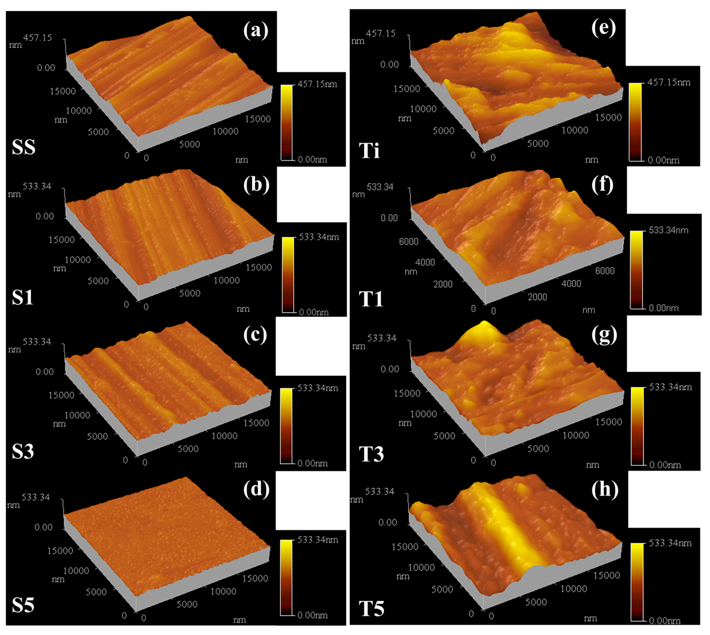
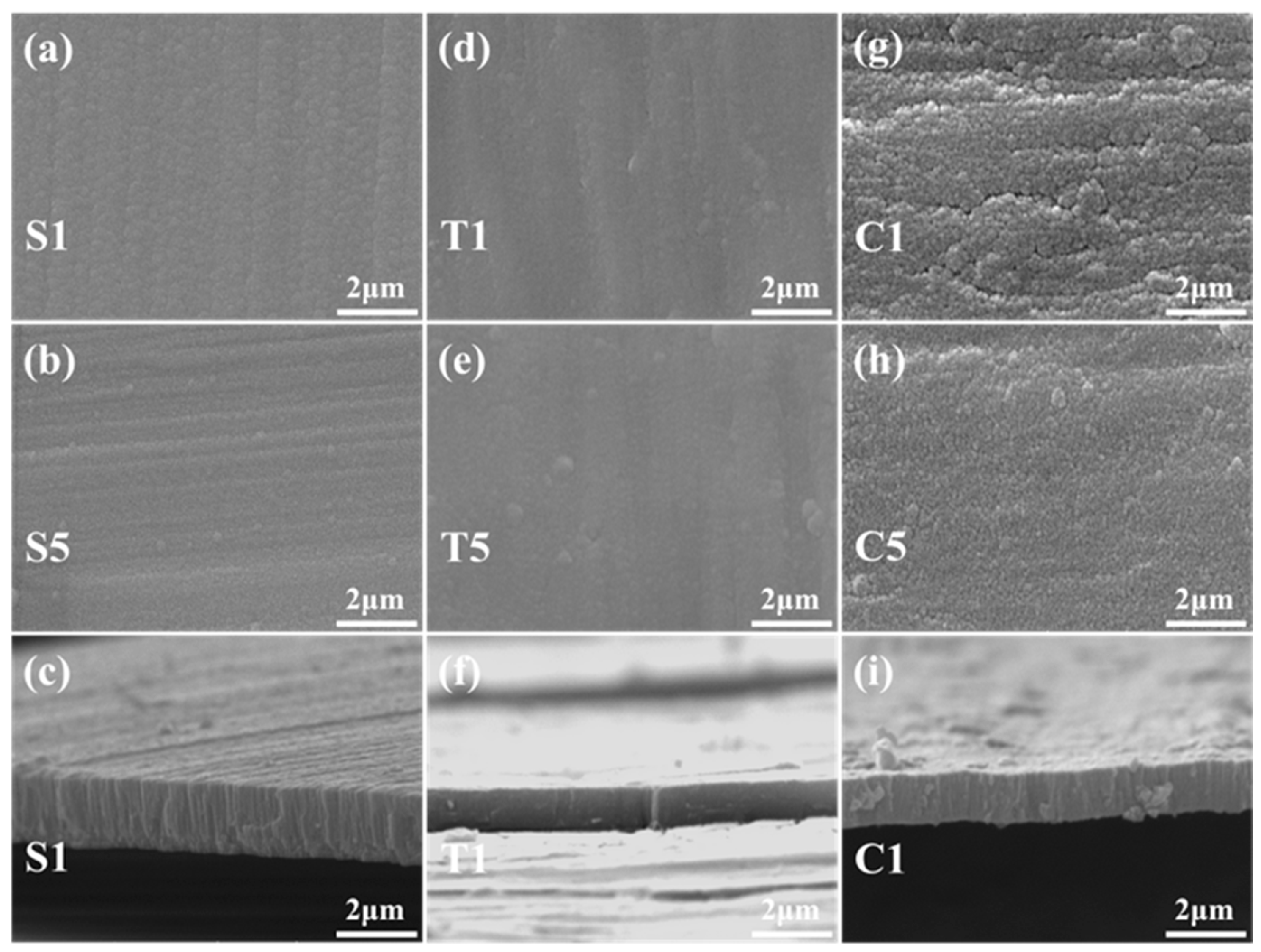
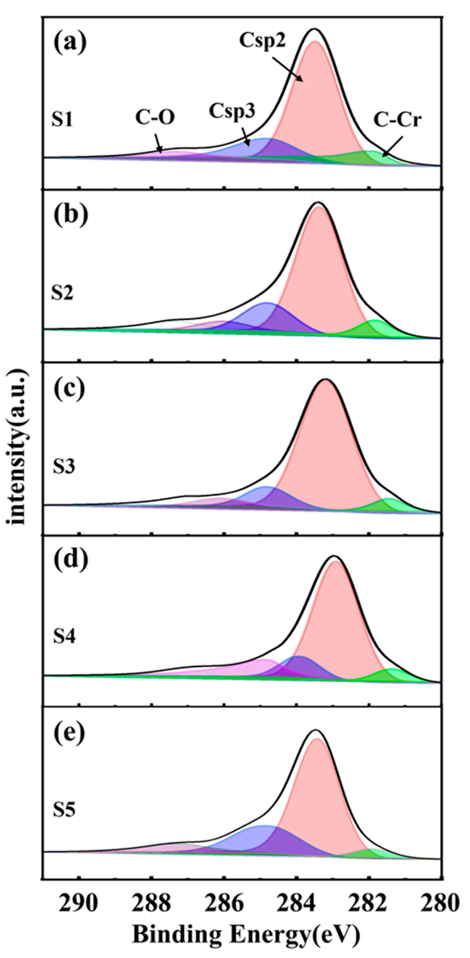
3.1. The Microstructure and Phase Composition of the Film
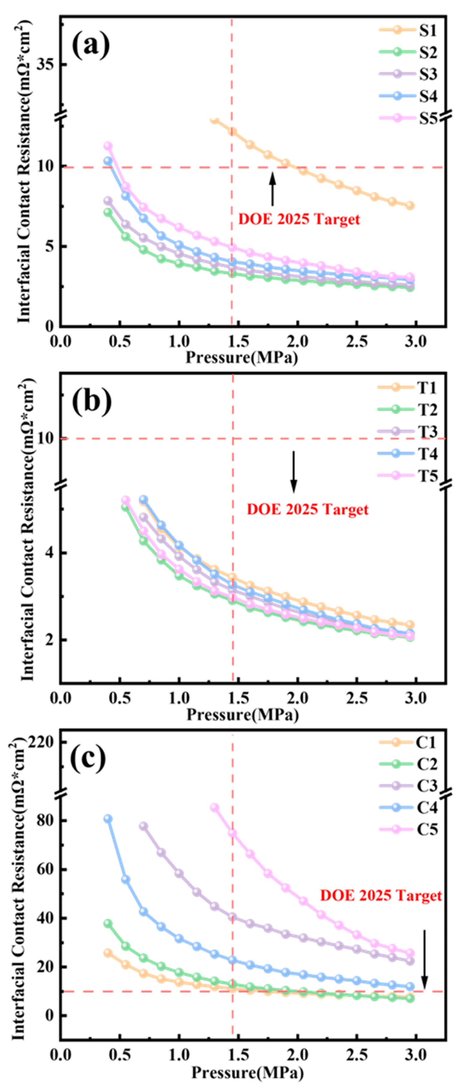
We used AFM to evaluate the surface roughness of the samples, as illustrated in Figure 3. Initially, we observed discernible striped patterns on the surfaces of both substrates, as depicted in Figure 3a,e. These were attributed to the utilization of unpolished commercial SS316L foil and Ti foil as substrates, with the stripes being remnants from the rolling process. The surface roughness (Sa) of the SS substrate was determined to be 12.1 nm, while that of the Ti substrate was found to be 43.1 nm. The surface roughness measurements for S1, S3, and S5 were 18.2 nm, 16.0 nm, and 4.5 nm, respectively. T1, T3, and T5 had surface roughness values of 24.2 nm, 27.8 nm, and 49.53 nm, respectively. Based on these findings, it can be concluded that the sputtered films are able to reduce substrate roughness and produce a smoother surface. However, the overall roughness is still affected by the rolling stripes because of the large scanning range.
Figure 4 displays the microstructure of the thin films produced under various conditions. The SEM images reveal clear striped patterns on the sample surface, indicating thin films with strong adhesion to the substrate, featuring a uniform morphology aligned with the substrate. From Figure 4a,d, it is evident that the film surfaces do not have any pinhole structures and are relatively intact and dense. However, as depicted in Figure 4b,e, with the increase in gas flow rate, the films become smoother and denser. The increase in gas flow rate during sputtering is believed to result in higher-density high-energy particles, leading to a finer bombardment of target atoms during the deposition process. This leads to fewer occurrences of agglomeration. Additionally, the introduction of Cr atoms, which hold a strong affinity with C atoms [30], produces grain refinement in films. A significant reduction in film defects and a denser structure can be seen in Figure 4g when compared to Figure 4d. From Figure 4c, it is evident that the upper a-C:Cr layer in the S-series multilayer film structure has a columnar structure. The acidic liquid within the PEMFC can corrode the metal BPPs located underneath the film through the gaps in the columnar structure. Nevertheless, the dense Ti transition layer and a-C:Cr layer create an interlocking structure, which effectively prevents the corrosion from deteriorating [17]. On the contrary, the T and C series of single-layer films, as demonstrated in Figure 4f,i, comprise a columnar structure spanning the entire cross-section. To summarize, it is expected that the S-series specimens will offer commendable corrosion resistance.
Figure 5 shows the XRD patterns of the SS/Ti/a-C:Cr multilayer films. The data was collected using a grazing incidence angle of 2° to minimize the influence of the SS substrate. From the patterns, it can be observed that the crystalline signals originate from the carbides of Cr and chromium [31,32]. The peaks at 44.3° and 64.5° correspond to the (110) and (200) crystal planes of Cr, respectively. The 38.3° peak corresponds to the (321) crystal plane of Cr7C3, and no carbon peak signal is observed, indicating the presence of amorphous carbon in the film.
Taking the result of the XPS test of the multilayer film SS/Ti/a-C:Cr as an example, Figure 6 shows the C1s spectrum. Carbon is the primary constituent of the film. After employing Gaussian fitting, the obtained outcomes demonstrate that the sp2 peak is situated at 283.6 eV, while the sp3 peak is located at 284.8 eV. The C−O bond corresponds to 287.2 eV, whereas the C−Cr bond aligns with 281.8 eV [33]. The peak corresponding to the C−O bond with the highest binding energy is attributed to carbon compounds, indicating that it is a product of oxidation due to the sample being exposed to air. All XPS data were fitted using the same method as mentioned above. The carbon atomic content in different chemical states and the ratio sp2−C/sp3−C was directly calculated based on the ratio of the corresponding peak area to the total C1s peak area, as demonstrated in Table 2.
As amorphous carbons (sp and sp2 hybridisation) are generally more conductive and chemically oxidizable than crystalline diamond carbon, the chemical corrosion rate is higher, especially for sp2-compared to sp3-hybridised carbon. Using X-ray photoelectron spectroscopy (XPS) and Raman spectroscopy, previous corrosion studies with DLC showed that corrosion takes place predominantly via a reduction in the carbon sp2 content, resulting in the formation of oxides of CO, C–OH, C–O and C(=O)–OH [34,35].
The sp3 structure of carbon atoms resembles that of a diamond, providing high resistance to corrosive ions. Conversely, the sp2 structure of carbon atoms resembles that of graphite, which enhances the conductivity of amorphous carbon films. The fitting results reveal that the Ti/a-C:Cr sample exhibits superior conductivity compared to the SS/Ti/a-C:Cr sample.
S. Groudeva-Zotova et al. [36] found that C−Cr films undergo a phase structure transition to an amorphous C, Cr phase and a Cr3C2 phase when the carbon content surpasses 60%. Based on the XRD spectra, the Cr-doped amorphous carbon films generated via mid-frequency magnetron sputtering mainly comprise amorphous carbon, metallic Cr, and chromium carbides. The phenomenon of increased conductivity and decreased corrosion resistance in high-sp2 carbon structures is consistent with classical carbon material theory; high-sp2 regions (such as nanocrystalline graphite) increase conductivity through π electron networks, but the breaking of sp3 bonds leads to an exponential increase in corrosion current density.

3.2. ICR Evaluation

One of the important functions of BPPs is to collect and conduct current, making conductivity a critical performance indicator. In accordance with the improved test method presented by Wang et al. [29], we characterized the surface contact resistance of samples, the results of which are presented in Figure 7. The ICR value initially experiences a rapid decrease with increasing pressure before leveling off. From Figure 3’s microstructure, we observe that although the sample surface appears notably smooth, it in fact demonstrates a striped structure with undulations. When the pressure is low, the carbon paper solely connects with the elevated stripes. As the pressure increases, the interaction between the carbon paper and the sample’s surface grows more adequate, leading to a reduction in resistance. Under the testing standard conditions mandated by the DOE 2025 testing protocol, the S series samples exhibit ICR values of 12.17, 3.30, 3.70, 4.05, and 4.93 mΩ·cm2, satisfying the commercial standards set by DOE 2025 in most cases. For the T series samples, the ICR values are 3.44, 2.90, 3.14, 3.27, and 2.98 mΩ·cm2, respectively, all of which meet the commercial standards of DOE 2025. The ICR values of the C series are 11.12, 12.95, 40.51, 22.83, and 74.91 mΩ·cm2, respectively. They are compared to the ICR value of bare SS316L, which measures 188.6 mΩ·cm2 [37], and the ICR value of bare Ti, which measures 175.5 mΩ·cm2 [38]. The coatings we prepared significantly reduce the ICR value of the metal BPPs. The T series, which is doped with the Cr element in the film, reduces the ICR value compared to the C series [30]. This trend is consistent with the previous XPS test results. The Ti/a-C:Cr sample displays a slightly lower ICR value. The minimum ICR values for both S and T series samples are attained under condition 2, exhibiting a variance of 0.40 mΩ·cm2.

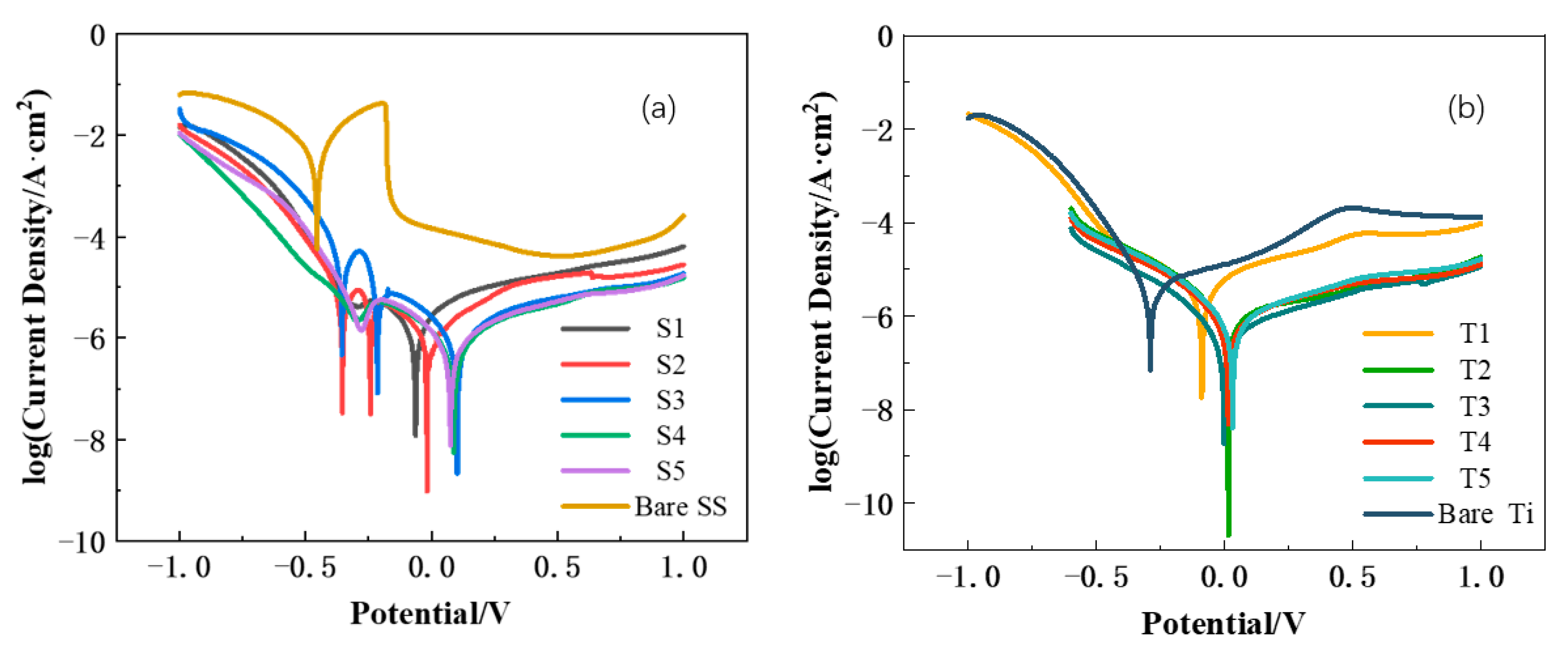
3.3. Corrosion Resistance Evaluation

Due to the long-term operation of BPPs in acidic environments, their resistance to corrosion is a crucial factor in evaluating their performance. We used Toray TGP-H-060 carbon paper (thickness 180 μ m) with a compression rate controlled at 30 ± 0.5% (GB/T 20042.5-2023 standard [39]). To measure the corrosion resistance of the samples, we conducted dynamic potential polarization tests on them in a simulated environment solution for PEMFC at a constant temperature of 70 °C. The solution consisted of 0.5 M H2SO4 and 5 ppm HF. The C series single a-C film exhibited inadequate substrate adhesion, which rendered it susceptible to detachment and impervious to chemical testing. Figure 8 illustrates the test findings for the remaining samples. As an illustrations of those outcomes, the dynamic potential polarization curve test for the Ti/a-C:Cr sample indicated a substantial increase in the polarization potential of BPPs with the protection of the thin film and a corresponding decrease in corrosion current density.
The Tafel extrapolation method [40] was used to analyze the test results, yielding the corrosion current density and corrosion potential at 0.6 V for every sample. The results can be seen in Table 3.
Figure 9a visually shows that the multilayer film structure significantly improves the corrosion resistance of SS316L BPPs. Conditions S3, S4, and S5 meet the DOE 2025 standard, and an increasing airflow results in a decreasing trend in Icorr; this is consistent with our predicted outcome based on surface morphology observations. In Figure 9b, the Ti/a-C:Cr sample demonstrates that the diamond-like sp3 structure of C atoms effectively resists corrosion caused by corrosive ions. Conversely, a graphite-like sp2 structure can negatively impact corrosion resistance if the ratio of sp2/sp3 is too high. The sp2/sp3 ratio for conditions S1, T2, and T5 is approximately 7, which results in the highest corrosion current density within this group. In contrast, the S3, S4, T1, and T3 samples exhibit a sp2/sp3 ratio of about 6, which produces favorable outcomes. Significantly, the S4 sample has the lowest corrosion current density of 0.69 μA/cm2 among the S series, while the T3 sample has the lowest corrosion current density of 0.62 μA/cm2 among the T series. These findings suggest that by suitably optimizing the process and adjusting the sp2/sp3 ratio within the film, superior corrosion resistance and conductivity can be achieved.

3.4. Hydrophobicity

In addition to supporting conductivity, BPPs must efficiently remove the water produced during the reaction. Inadequate discharge of liquid water from the battery impedes the transportation of reactants, reducing the battery efficiency and increasing PEMFC corrosion. The contact angles of water on different samples were measured using a contact angle measurement instrument, as demonstrated in Figure 10. The bare Ti sample displayed the weakest hydrophobicity with the smallest contact angle measuring 65.35°. Subsequently, after undergoing thin film coating, the water contact angles for all samples showed improved hydrophobic performance, generally exceeding 85°.

4. Conclusions

In this study, we successfully fabricated an SS/Ti/a-C:Cr multilayer film on SS316L substrates and a Ti/a-C:Cr single-layer film on titanium substrates using mid-frequency magnetron sputtering under controlled pressure conditions. Our results demonstrate that increasing the gas flow rate during deposition enhances the production of high-energy sputtering particles, which promotes more refined atomic bombardment and significantly reduces particle agglomeration. As a result, the films become smoother, denser, and less porous, resulting in enhanced corrosion resistance. The sp2/sp3 ratio has a close relationship with both electrical conductivity and corrosion resistance. As the ratio increases, electrical conductivity increases, but corrosion resistance decreases. In both the SS/Ti/a-C:Cr multilayer film and the Ti/a-C:Cr single-layer film, a high sp2/sp3 ratio effectively prevents deep corrosion, leading to a low corrosion current density and good corrosion resistance. Optimization of the film layer structure and preparation process results in an optimal ICR of 3.30 mΩ·cm2 for the SS/Ti/a-C:Cr multilayer film sample, with an Icorr (corrosion current density) of 0.69 μA/cm2. The best ICR for the Ti/a-C:Cr single-layer film sample is 2.90 mΩ·cm2, with an Icorr of 0.62 μA/cm2. Both samples fulfill the DOE 2025 standard. The minor difference in performance between the two sample sets supports the possibility of utilizing SS316L BPPs instead of titanium BPPs.

Author Contributions

Conceptualization, Y.Z. and S.L.; methodology, S.W.; software, M.M.; validation, M.C., J.Y. and C.Y.; formal analysis, Y.Z.; investigation, S.L.; resources, S.W.; data curation, Y.Z.; writing—original draft preparation, S.L.; writing—review and editing, S.W.; visualization, W.L.; supervision, S.W.; project administration, W.L.; funding acquisition, W.L. All authors have read and agreed to the published version of the manuscript.

Funding

This work was supported by the National Natural Science Foundation of China under Grant no. 52202331.

Data Availability Statement

Data is contained within the article. The original contributions presented in this study are included in the article. Further inquiries can be directed to the corresponding authors.

Conflicts of Interest

Author Jiao Yang was employed by the company Shenzhen Center Power Tech Co.,Ltd. The remaining authors declare that the research was conducted in the absence of any commercial or financial relationships that could be construed as a potential conflict of interest.

References

  1. Asri, N.F.; Husaini, T.; Sulong, A.B.; Majlan, E.H.; Daud, W.R.W. Coating of stainless steel and titanium bipolar plates for anticorrosion in PEMFC: A review. Int. J. Hydrogen Energy 2017, 42, 9135–9148. [Google Scholar] [CrossRef]
  2. Peng, L.; Yi, P.; Lai, X. Design and manufacturing of stainless steel bipolar plates for proton exchange membrane fuel cells. Int. J. Hydrogen Energy 2014, 39, 21127–21153. [Google Scholar] [CrossRef]
  3. Tu, Z.; Zhang, H.; Luo, Z.; Liu, J.; Wan, Z.; Pan, M. Evaluation of 5 kW proton exchange membrane fuel cell stack operated at 95 degrees C under ambient pressure. J. Power Sources 2013, 222, 277–281. [Google Scholar] [CrossRef]
  4. Yu, Y.; Tu, Z.; Zhang, H.; Zhan, Z.; Pan, M. Comparison of degradation behaviors for open-ended and closed proton exchange membrane fuel cells during startup and shutdown cycles. J. Power Sources 2011, 196, 5077–5083. [Google Scholar] [CrossRef]
  5. Tan, Q.; Wang, Y. Research Progress on Corrosion Behavior and Surface Protection of Stainless Steel Bipolar Plate of Proton Exchange Membrane Fuel Cell. Surf. Technol. 2021, 50, 192–200. [Google Scholar]
  6. Tang, Y.; Yuan, W.; Pan, M.; Wan, Z. Feasibility study of porous copper fiber sintered felt: A novel porous flow field in proton exchange membrane fuel cells. Int. J. Hydrogen Energy 2010, 35, 9661–9677. [Google Scholar] [CrossRef]
  7. Yi, P.; Zhang, D.; Qiu, D.; Peng, L.; Lai, X. Carbon-based coatings for metallic bipolar plates used in proton exchange membrane fuel cells. Int. J. Hydrogen Energy 2019, 44, 6813–6843. [Google Scholar] [CrossRef]
  8. Lee, J.-B.; Oh, I.H. Electrochemical characteristics and interfacial contact resistance of multi-layered Ti/TiN coating for metallic bipolar-plate of polymer electrolyte membrane fuel cells. Met. Mater. Int. 2014, 20, 629–639. [Google Scholar] [CrossRef]
  9. Chen, H.; Liu, H.B.; Yang, L.; Li, J.X.; Yang, L. Study on the preparation and properties of novolac epoxy/graphite composite bipolar plate for PEMFC. Int. J. Hydrogen Energy 2010, 35, 3105–3109. [Google Scholar]
  10. Huang, J.H.; Baird, D.G.; McGrath, J.E. Development of fuel cell bipolar plates from graphite filled wet-lay thermoplastic composite materials. J. Power Sources 2005, 150, 110–119. [Google Scholar] [CrossRef]
  11. Jin, J.; Liu, H.; Zheng, D.; Zhu, Z. Effects of Mo content on the interfacial contact resistance and corrosion properties of CrN coatings on SS316L as bipolar plates in simulated PEMFCs environment. Int. J. Hydrogen Energy 2018, 43, 10048–10060. [Google Scholar] [CrossRef]
  12. Bondarenko, A.V.; Islamov, S.R.; Ignatyev, K.V.; Mardashov, D.V. Laboratory studies of polymer compositions for well-kill under increased fracturing. Perm J. Pet. Min. Eng. 2020, 20, 37–48. [Google Scholar] [CrossRef] [PubMed]
  13. Kumar, A.; Ricketts, M.; Hirano, S. Ex situ evaluation of nanometer range gold coating on stainless steel substrate for automotive polymer electrolyte membrane fuel cell bipolar plate. J. Power Sources 2010, 195, 1401–1407. [Google Scholar] [CrossRef]
  14. Yi, P.; Zhu, L.J.; Dong, C.F.; Xiao, K. Corrosion and interfacial contact resistance of 316L stainless steel coated with magnetron sputtered ZrN and TiN in the simulated cathodic environment of a proton-exchange membrane fuel cell. Surf. Coat. Technol. 2019, 363, 198–202. [Google Scholar] [CrossRef]
  15. Li, J.L.; Xu, Z.L.; Li, Y.J.; Ma, X.Z.; Mo, J.M.; Weng, L.Y.; Liu, C.Y. Intergranular passivation of the TiC coating for enhancing corrosion resistance and surface conductivity in stainless-steel bipolar plates. J. Mater. Sci. 2021, 56, 8689–8703. [Google Scholar] [CrossRef]
  16. Wang, Y.L.; Zhang, S.H.; Lu, Z.X.; Wang, L.S.; Li, W.H. Preparation and performances of electrically conductive Nb-doped TiO2 coatings for 316 stainless steel bipolar plates of proton-exchange membrane fuel cells. Corros. Sci. 2018, 142, 249–257. [Google Scholar] [CrossRef]
  17. Wu, M.G.; Lu, C.D.; Hong, T.; Chen, G.H.; Wen, D.H. Chromium interlayer amorphous carbon film for 304 stainless steel bipolar plate of proton exchange membrane fuel cell. Surf. Coat. Technol. 2016, 307, 374–381. [Google Scholar]
  18. Akula, S.; Kalaiselvi, P.; Sahu, A.K.; Chellammal, S. Electrodeposition of conductive PAMT/PPY bilayer composite coatings on 316L stainless steel plate for PEMFC application. Int. J. Hydrogen Energy 2021, 46, 17909–17921. [Google Scholar] [CrossRef]
  19. Feng, K.; Shen, Y.; Sun, H.L.; Liu, D.L.; An, Q.Z.; Cai, X.; Chu, P.K. Conductive amorphous carbon-coated 316L stainless steel as bipolar plates in polymer electrolyte membrane fuel cells. Int. J. Hydrogen Energy 2009, 34, 6771–6777. [Google Scholar] [CrossRef]
  20. Che, J.; Yi, P.Y.; Peng, L.F.; Lai, X.M. Impact of pressure on carbon films by PECVD toward high deposition rates and high stability as metallic bipolar plate for PEMFCs. Int. J. Hydrogen Energy 2020, 45, 16277–16286. [Google Scholar] [CrossRef]
  21. DOE/EE-2114; Fuel Cell System Cost–2025. U.S. Department of Energy: Washington, DC, USA, 2022.
  22. Yang, S.; Teer, D.G. Investigation of sputtered carbon and carbon/chromium multi-layered coatings. Surf. Coat. Technol. 2000, 131, 412–416. [Google Scholar] [CrossRef]
  23. Wei, C.H.; Yen, J.Y. Effect of film thickness and interlayer on the adhesion strength of diamond like carbon films on different substrates. Diam. Relat. Mater. 2007, 16, 1325–1330. [Google Scholar] [CrossRef]
  24. Bi, F.F.; Li, X.B.; Yi, P.Y.; Hou, K.; Peng, L.F.; Lai, X.M. Characteristics of amorphous carbon films to resist high potential impact in PEMFCs bipolar plates for automotive application. Int. J. Hydrogen Energy 2017, 42, 14279–14289. [Google Scholar] [CrossRef]
  25. Li, X.B.; Hou, K.; Qiu, D.K.; Yi, P.Y.; Lai, X.M. A first principles and experimental study on the influence of nitrogen doping on the performance of amorphous carbon films for proton exchange membrane fuel cells. Carbon 2020, 167, 219–229. [Google Scholar] [CrossRef]
  26. Zhang, D.; Yi, P.Y.; Peng, L.F.; Lai, X.M.; Pu, J.B. Amorphous carbon films doped with silver and chromium to achieve ultra-low interfacial electrical resistance and long-term durability in the application of proton exchange membrane fuel cells. Carbon 2019, 145, 333–344. [Google Scholar] [CrossRef]
  27. Belousov, A.; Lushpeev, V.; Sokolov, A.; Sultanbekov, R.; Tyan, Y.; Ovchinnikov, E.; Shvets, A.; Bushuev, V.; Islamov, S. Experimental Research of the Possibility of Applying the Hartmann–Sprenger Effect to Regulate the Pressure of Natural Gas in Non-Stationary Conditions. Processes 2025, 13, 1189. [Google Scholar] [CrossRef]
  28. Davies, D.P.; Adcock, P.L.; Turpin, M.; Rowen, S.J. Stainless steel as a bipolar plate material for solid polymer fuel cells. J. Power Sources 2000, 86, 237–242. [Google Scholar] [CrossRef]
  29. Wang, H.L.; Sweikart, M.A.; Turner, J.A. Stainless steel as bipolar plate material for polymer electrolyte membrane fuel cells. J. Power Sources 2003, 115, 243–251. [Google Scholar] [CrossRef]
  30. Hou, K.; Yi, P.; Li, X.; Peng, L.; Lai, X. The effect of Cr doped in amorphous carbon films on electrical conductivity: Characterization and mechanism. Int. J. Hydrogen Energy 2021, 46, 30841–30852. [Google Scholar] [CrossRef]
  31. Chen, X.; Peng, Z.; Fu, Z.; Yue, W.; Yu, X.; Wang, C. Influence of individual Cr-C layer thickness on structural and tribological properties of multilayered Cr-C/a-C:Cr thin films. Surf. Coat. Technol. 2010, 204, 3319–3325. [Google Scholar] [CrossRef]
  32. Hovsepian, P.E.; Kok, Y.N.; Ehiasarian, A.P.; Haasch, R.; Wen, J.G.; Petrov, I. Phase separation and formation of the self-organised layered nanostructure in C/Cr coatings in conditions of high ion irradiation. Surf. Coat. Technol. 2005, 200, 1572–1579. [Google Scholar] [CrossRef]
  33. Detroye, M.; Reniers, F.; Buess-Herman, C.; Vereecken, J. AES-XPS study of chromium carbides and chromium iron carbides. Appl. Surf. Sci. 1999, 144–145, 78–82. [Google Scholar] [CrossRef]
  34. Elam, F.M.; Hsia, F.C.; van Vliet, S.; Bliem, R.; Yang, L.; Weber, B.; Franklin, S.E. The influence of corrosion on diamond-like carbon topography and friction at the nanoscale. Carbon 2021, 179, 590–599. [Google Scholar] [CrossRef]
  35. Tunmee, S.; Photongkam, P.; Euaruksakul, C.; Takamatsu, H.; Zhou, X.; Wongpanya, P.; Komatsu, K.; Kanda, K.; Ito, H.; Saitoh, H. Investigation of pitting corrosion of diamond-like carbon films using synchrotron-based spectromicroscopy. J. Appl. Phys. 2016, 120, 195303. [Google Scholar] [CrossRef]
  36. Groudeva-Zotova, S.; Vitchev, R.G.; Blanpain, B. Phase composition of Cr-C thin films deposited by a double magnetron sputtering system. Surf. Interface Anal. 2000, 30, 544–548. [Google Scholar] [CrossRef]
  37. Mi, B.; Wang, Q.; Qi, T.; Qin, Z.; Chen, Z.; Wang, H. Performance and structure of Ti-doped amorphous carbon/CrN/Ti multilayer coating deposited on 316L stainless steel for use as bipolar plate in proton exchange membrane fuel cell. J. Alloys Compd. 2023, 943, 169080. [Google Scholar] [CrossRef]
  38. Chen, L.; Liu, R.; Zhang, B.; Lv, J.; Zhang, J. Nano-Cr2N dominated films with high conductivity and strong corrosion resistance for Ti bipolar plates. Mater. Des. 2022, 224, 111305. [Google Scholar] [CrossRef]
  39. GB/T 20042.5-2023; Proton Exchange Membrane Fuel Cell—Part 5: Test Methods for Bipolar Plates. China Electrical Equipment Industry Association: Beijing, China, 1 October 2023.
  40. McCafferty, E. Validation of corrosion rates measured by the Tafel extrapolation method. Corros. Sci. 2005, 47, 3202–3215. [Google Scholar] [CrossRef]
Figure 1. (a) S-series film fabrication process. An a-C:Cr layer is prepared with different parameters by adjusting the Ar atmosphere after depositing a Ti buffer layer. (b) T and C-series film fabrication process. On the Ti substrate, different process parameters are adjusted to deposit amorphous carbon films and a-C:Cr films in different Ar atmospheres, forming the C and T series, respectively.
Energies 18 03270 g001
Figure 2. Schematic diagram of the ICR principle. The sample is composed of carbon paper and copper plate on both sides, respectively. During the test, a fixed current is applied, and the pressure on the sample is gradually increased through the copper plate. The values on the voltmeter are recorded. After that, the sample is taken out, and the same procedure is repeated. The data from the two experiments are calibrated to obtain the true contact resistance.
Energies 18 03270 g002
Figure 3. AFM images. (ad) show the AFM images of the SS substrate and S series samples; (eh) show the AFM images of the Ti substrate and T series samples.
Energies 18 03270 g003
Figure 4. SEM images of the surface and cross-section morphology of the film. (ac) are the s series samples, (df) are the T series samples, and (gi) are the introduced C series samples.
Energies 18 03270 g004
Figure 5. It shows the XRD patterns of the SS/Ti/a-C:Cr multilayer films. The samples were denoted as S1, S2, S3, S4, and S5, corresponding to the argon gas flow rates from low to high (300/350/400/450/500 sccm).
Energies 18 03270 g005
Figure 6. XPS spectra of S-series thin films. S1–S5 correspond to samples prepared at low to high argon flow rates (300/350/400/450/500 sccm), as shown in the XPS spectra labeled S1, S2, S3, S4, and S5, respectively.
Energies 18 03270 g006
Figure 7. Graphs illustrating the variation of contact resistance with pressure for the S, T, and C series. (a) shows the variation of contact resistance with pressure in the s series. (b) shows the variation of contact resistance of the T series with pressure. (c) shows the variation of C-series contact resistance with pressure [21].
Energies 18 03270 g007
Figure 8. Dynamic potential polarization curves, with (a) representing the S series and (b) representing the T series.
Energies 18 03270 g008
Figure 9. Corrosion current for the S series (a) and the T series (b) [21].
Energies 18 03270 g009
Figure 10. Water contact angles of SS substrate, Ti substrate, S series, and T series. (a) Water contact angle for SS substrate; (bd) are the water contact angles of the S series, corresponding to argon flow rates (300/400/500 sccm); (e) Water contact angle for SS substrate; (fh) is the water contact angle of the T series, and a-C: Cr thin films were obtained using argon gas flow rates of (300/400/500 sccm).
Energies 18 03270 g010
Table 1. DOE 2025 bipolar plates specification requirements.
PropertyTarget
Interface contact resistance (1.4 MPa)<10 (mΩ·cm2)
Corrosion current density<1 (μA·cm−2)
Cost of production<2 ($·KW−1)
Table 2. The carbon atom content in different chemical states in each sample.
SampleT1T2T3T4T5
C(sp2)/at%0.720.80.70.730.78
C(sp3)/at%0.110.110.120.130.11
C-Cr/at%0.10.040.130.090.06
C-O/at%0.070.050.050.050.05
C(sp2)/C(sp3)6.457.346.035.636.93
SampleS1S2S3S4S5
C(sp2)/at%0.750.660.710.70.71
C(sp3)/at%0.10.170.110.120.16
C-Cr/at%0.070.080.10.10.05
C-O/at%0.080.090.080.080.08
C(sp2)/C(sp3)7.493.876.625.974.57
Table 3. Icorr and potential values from potentiodynamic polarization curves.
SampleSSS1S2S3S4S5
Icorr (μA/cm2)57382.272.140.940.690.730.650.72
Ecorr (mV)−455−438−451−446−452−448−456−448
SampleTiT1T2T3T4T5
Icorr (μA/cm2)4.060.761.340.620.730.652.004.62
Ecorr (mV)−290144336413866137
Disclaimer/Publisher’s Note: The statements, opinions and data contained in all publications are solely those of the individual author(s) and contributor(s) and not of MDPI and/or the editor(s). MDPI and/or the editor(s) disclaim responsibility for any injury to people or property resulting from any ideas, methods, instructions or products referred to in the content.

