Abstract
Polymer electrolyte membrane fuel cells (PEMFCs) are emerging as the next-generation powertrain for unmanned aerial vehicles (UAVs) due to their high energy density and long operating duration. PEMFCs are subject to icing and performance degradation problems at sub-zero temperatures, especially at high altitudes. Therefore, an effective preheating system is required to ensure stable PEMFC operation in high-altitude environments. This study aimed to mathematically model a shell-and-tube heat exchanger that utilizes waste heat recovery to prevent internal and external PEMFC damage in cold, high-altitude conditions. The waste heat from the PEMFC is estimated based on the thrust of the MQ-9 Reaper, and the proposed heat exchanger must be capable of heating air to −5 °C. As the heat exchanger utilizes only waste heat, the primary energy consumption arises from the coolant pumping process. Calculation results indicated that the proposed heat exchanger design improved the overall system efficiency by up to 15.7%, demonstrating its effectiveness in utilizing waste heat under aviation conditions.
1. Introduction
UAVs (unmanned aerial vehicles) are emerging as one of the core technologies of the Fourth Industrial Revolution and are actively utilized across various industries, including both civilian [1,2] and military sectors [3]. Among them, MALE (medium-altitude long-endurance) UAVs are employed for long-duration missions such as border patrol, search and rescue operations, wildfire monitoring, and atmospheric observation [2]. Table 1 presents the specifications of commercially deployed MALE UAVs by country.

Table 1.
MALE UAV status and specifications by country.
In response to increasing environmental concerns over greenhouse gas emissions, internal combustion engines in MALE UAVs are progressively being replaced by electric propulsion systems [8]. Li-ion batteries are widely used as a power source for UAVs, but their low energy density is a significant limitation. Such batteries quickly discharge and require a long time to recharge, which limits their use in the operation of MALE UAVs [8,9,10]. Larger UAVs require a higher power output, necessitating the installation of additional batteries. As the number of batteries increases, the overall system weight also rises, leading to spatial constraints and reduced flight efficiency [9].
To solve these problems, PEMFCs (polymer electrolyte membrane fuel cells) are emerging as the next-generation powertrain in relation to UAVs [11,12,13]. PEMFCs are well-suited for electric propulsion systems in UAVs due to their high energy density, low weight and vibration, low operating temperature, and quiet operation. PEMFCs generate electrical energy through a chemical reaction between hydrogen and oxygen, emitting only water as a byproduct, which makes them an environmentally friendly power source [13]. However, the relatively low power density of PEMFCs makes it difficult for them to handle rapid load changes—such as those encountered during takeoff and landing—on their own [13]. In addition, aircraft applications introduce extra challenges, including low-temperature and low-pressure operation, icing risk, and strict hydrogen safety regulations [14]. Consequently, practical airframes require hybrid architectures that pair the fuel cell with a Li-ion battery, along with dedicated thermal water management and comprehensive safety measures [13,14]. Despite these hurdles, recent technological advancements have demonstrated the successful application of PEMFCs in aviation through experimental and commercial flights. In 2023, ZeroAvia (USA/UK) successfully operated a 19-seat aircraft that was equipped with a hydrogen–electric engine powered by a PEMFC [15]. In 2024, Joby Aviation (USA) and H2FLY (Germany) successfully flew a hydrogen-powered VTOL (vertical takeoff and landing aircraft) for 523 miles [16].
PEMFCs for aircraft are exposed to extreme climates at high altitudes. At such altitudes, sub-zero temperatures freeze the water generated inside the cathode CL (catalyst layer), blocking its pores, hindering airflow, and causing oxygen starvation [14]. Zeng et al. [14] conducted a study on water and heat management and cold start of PEMFC system on UAV. The experiments showed that the fuel cell could be started at −10 °C, whereas lower temperatures would require additional cold-start strategies. Rajbongshi et al. [17] investigated cell voltage performance and cold start at sub-zero temperatures; they found that, at temperatures below −15 °C, ice formed rapidly, resulting in a decline in cell voltage. Therefore, an effective air preheating mechanism is required to prevent the freezing of MEA (membrane electrode assembly) and to ensure reliable operation in high-altitude environments. Zhan et al. [18] proposed three preheating methods: air preheating, coolant preheating, and combined air and end plate preheating; they stated that the optimal preheating temperature is above −5 °C. However, preheating the PEMFC with an external heater consumes additional power, making it inefficient [17]. Thus, utilizing the waste heat from the PEMFC for preheating can reduce power consumption and improve overall system efficiency [19,20].
Antonio et al. [21] presented a vehicle heating system that utilizes the waste heat generated by a 12 kW PEMFC. The system, which is based on a cooling circuit and a heating radiator, achieved energy savings of 17%. Xu et al. [22] employed waste heat recovery in a PEMFC system for heavy-duty trucks powered by cryo-compressed hydrogen, using it to preheat the hydrogen. The efficiency of the heat exchanger was low, but it was sufficient to preheat the cryo-compressed hydrogen. Lu et al. [23] presented a waste heat recovery system for a 90 kW HEV (hydrogen–electric vehicle) to reduce the power of its PTC (positive temperature coefficient) heater in environments of −20 °C, −25 °C, and −30 °C. By using a liquid-to-liquid heat exchanger, the system reduced PTC heater power consumption by 57.6%, 48%, and 34.3%, respectively. While waste heat recovery systems for HEVs have been actively developed, their application in aviation PEMFC systems remains limited and underexplored.
This study aims to design a heat exchanger for the waste heat recovery system to prevent PEMFC icing and performance degradation caused by low temperatures at medium-to-high altitudes during MALE UAV operation. The waste heat generation of the PEMFC was calculated based on the flight power of the MQ-9 Reaper, which is a type of MALE UAV [4]. According to Zhan et al. [18], the incoming air to the PEMFC must be preheated to at least −5 °C, the threshold temperature below which MEA damage can occur. Since the waste heat generated by the PEMFC is used as the thermal energy source, the only power loss when heating the air is the power used to pump the coolant. Therefore, the designed heat exchanger must minimize pumping losses by maintaining a low pressure drop and must be sufficiently compact to fit within the UAV engine compartment. To meet these design objectives, the thermal and geometric characteristics of the system were analyzed under different altitude conditions and the power losses generated through waste heat recovery were compared and evaluated against those of external electric preheating.
2. Waste Heat Calculation of PEMFCs
2.1. Aircraft Specifications
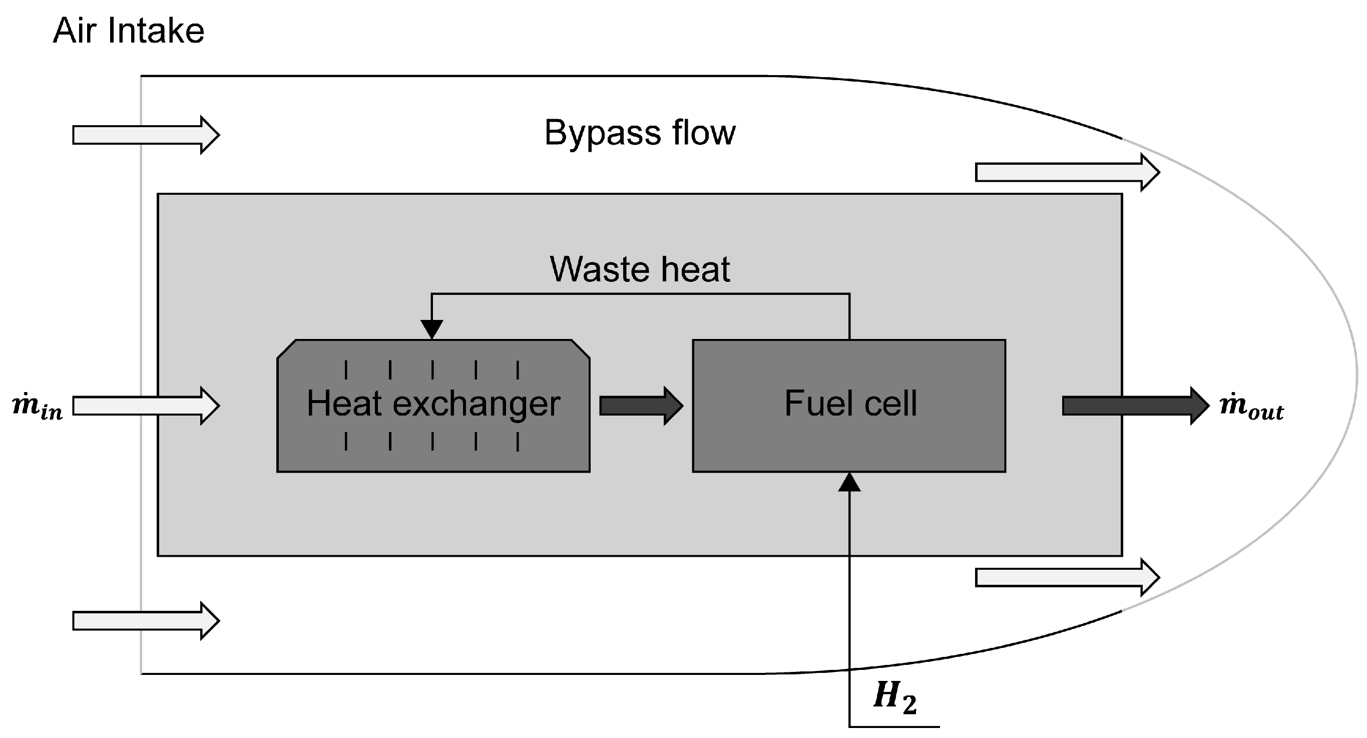
During flight, ambient air at a medium altitude enters the PEMFC system through the air intake. A portion of the ambient air bypasses the system, while the remainder passes through the heat exchanger to be preheated before entering the PEMFC. In this configuration, the heat exchanger is heated by the waste heat generated from the PEMFC and serves to preheat the incoming air before it enters the fuel cell. The preheated air then undergoes an electrochemical reaction with hydrogen to produce electricity, and the resulting waste heat is transferred back to the heat exchanger, forming a waste heat recovery system. This system not only improves thermal efficiency but also enables the stable operation of the PEMFC for UAVs under medium-altitude conditions. Figure 1 illustrates a schematic diagram of the waste heat recovery system in a PEMFC-based propulsion system. Table 2 presents the flight and engine specifications of the MQ-9 Reaper.
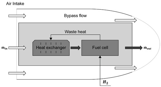
Figure 1.
Schematic diagram of a PEMFC waste heat recovery to air heat exchanger system.
Table 2.
Specifications of an MQ-9 Reaper flight and engine [4,24].
2.2. Heat Exchanger Selection
The waste heat recovery system for UAV-integrated PEMFCs must withstand low temperatures, frequent vibrations, and dynamic pressure variations resulting from altitude changes. Consequently, the heat exchanger should be carefully selected by a comprehensive evaluation of operating temperature and pressure ranges, heat transfer efficiency, and durability. In addition, as the heated coolant is utilized to preheat the incoming air, a liquid-to-gas heat exchanger configuration is essential. Accordingly, the heat exchanger types that satisfy these requirements are shell-and-tube, tube-fin, and printed-circuit designs [25].
Tube-fin heat exchangers can endure pressures of about 30 bar and temperatures up to 870 °C, and they are widely used in gas turbines and automotive systems [25,26]. Nevertheless, the narrow passages between closely spaced fins are prone to icing and fouling, which complicates maintenance and increases air-side pressure drop, thereby raising power consumption. Moreover, under harsh high-altitude environments, material degradation accelerates, and the direct exposure of the heat exchanger to free-stream airflow during cruise results in impact damage from ambient particles [25,26].
A printed-circuit heat exchanger can withstand extreme conditions (−200 to 900 °C and pressures above 600 bar) and it offers enhanced compactness and thermal efficiency compared to a shell-and-tube exchanger. However, due to their inherent susceptibility to clogging, the micro-channels require periodic chemical cleaning to ensure reliable operation [25,27]. Due to the cumbersome nature of handling cleaning chemicals, system design must be preemptively considered for such procedures, resulting in increased weight, design complexity, and maintenance costs [25,27].
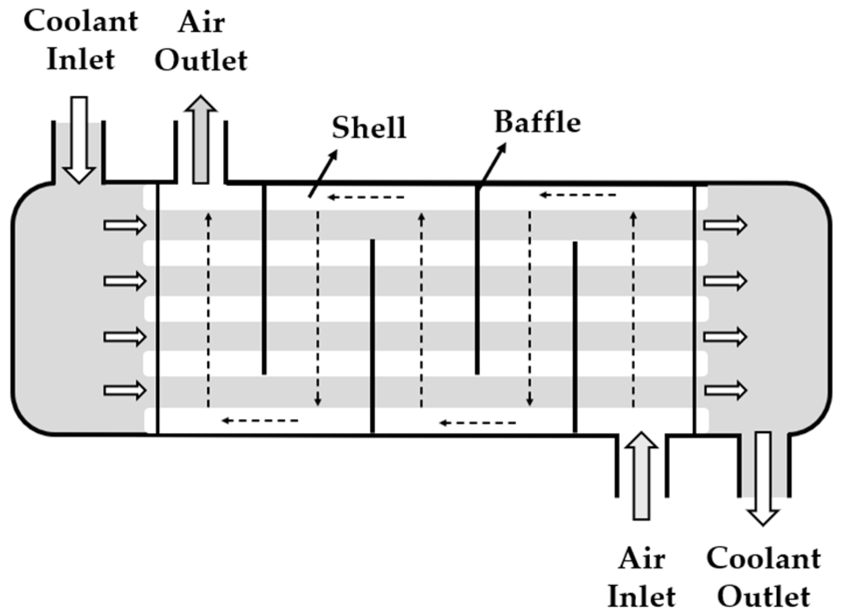
A shell-and-tube heat exchanger maintains excellent structural integrity under the low temperatures, pressure variations, and dynamic vibrations of high-altitude flight, and its tube bundle can be quickly withdrawn for on-site mechanical or chemical cleaning. Despite its relatively large size compared to the other two candidates, it can be readily integrated into the system using simple piping connections without additional mounting hardware [25,28]. For these reasons, the present study adopts a shell-and-tube exchanger as the most suitable option for waste heat recovery in high-altitude flight conditions. Figure 2 shows a schematic diagram of a shell-and-tube heat exchanger.
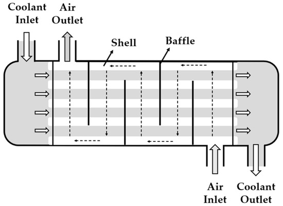
Figure 2.
Schematic diagram of a shell-and-tube heat exchanger system.
2.3. Air Properties
To determine the properties of the air entering the PEMFC during the MQ-9 Reaper flight, the temperature, pressure, and density of air at various altitudes were calculated. The calculations were based on the International Standard Atmosphere (ISA), and since the UAV operates within the troposphere, a temperature lapse rate of 6.5 °C/km was applied [29].
where
- is the air temperature by altitude;
- is the percentage decrease in temperature ();
- is the aircraft flight altitude.
Equation (2) applies the barometric formula to account for pressure reduction in the troposphere, assuming a constant temperature lapse rate [29].
where
- is the air pressure by altitude;
- is the standard atmospheric pressure (101,325 );
- is the standard atmosphere temperature (15 °C, 288.15 );
- is the gas constant (287.053 J/kg·K);
- is the gravitational acceleration (9.80665 ).
The air density was derived from the ideal gas equation using the values of and calculated from Equations (1) and (2) [29].
where
- is the air density.
Sutherland’s law, based on the ideal gas assumption, is an empirical formula that is used to correct the temperature-dependent viscosity of air, describing the relationship between temperature and dynamic viscosity [30].
where
- is air viscosity by altitude;
- is the standard atmospheric temperature (273.15 K);
- is the Sutherland temperature (111 K);
- is the reference air viscosity ( Pa s).
Table 3 shows the values of temperature (), pressure (), density (), viscosity (), and oxygen mole fraction at different altitudes, as calculated from the equations presented above.
Table 3.
Air properties by altitude.
Damage to PEMFCs and the MEA occurs below −15 °C [16,18]. At an altitude of 15,000 ft, the ambient temperature is relatively high, so there is no risk of cold-related damage, and thus a heat exchanger is not required [16,18]. At altitudes above 30,000 ft, the oxygen concentration drops significantly, making it difficult for the PEMFC to operate stably. In this study, the specifications of a heat exchanger utilizing the waste heat generated by a PEMFC propulsion system were calculated for flight environments between 10,000 and 30,000 ft.
2.4. PEMFC Waste Heat
Before calculating the waste heat required for air preheating, the total waste heat generated by the system is first evaluated to verify whether it is sufficient. The propulsion power is assumed to be supplied by a single PEMFC stack and a single Li-ion battery. To calculate the waste heat generated by the PEMFC, the DOH (degree of hybridization) of a hydrogen–electric propulsion system with an output equivalent to the engine thrust is determined [8]. The DOH represents the power ratio between the PEMFC and the battery in a hydrogen–electric propulsion system [8]. It is used to meet peak power demands by compensating for the low power density of the PEMFC via the integration of the PEMFC and the battery [9]. The waste heat generated by the PEMFC is obtained by calculating the reversible energy based on the power derived from the DOH.
The power output of a single engine consists of the sum of the PEMFC output and the battery output.
where
- is the power output of a single engine (691 );
- is the power output of the PEMFC;
- is the power output of the battery.
is calculated from the relationship between the ratio of the PEMFC and the power output of [8]. The is referenced in Beyond Aero’s hydrogen–electric propulsion system [31].
where
- is the degree of hybridization (0.47).
The reversible thermodynamic voltage of the PEMFC () is calculated using the Gibbs free energy change and Faraday’s constant [32].
where
- is the reversible thermodynamic voltage of the PEMFC (1.23 );
- is the Gibbs free energy for the electrochemical reaction (−237 );
- is the number of electrons transferred in the electrochemical reaction in (2);
- is Faraday’s constant (96,485 ).
Graf et al. [33] demonstrated that under low-pressure conditions, cell voltages below 0.6 V lead to a rapid decline in output and accelerated degradation. Therefore, this study adopts a minimum cell voltage of 0.6 V to ensure performance and durability at medium-altitude operation. Since the thermodynamic power output of the PEMFC is proportional to the theoretical voltage, the relationship can be expressed as follows:
where
- is the reversible thermodynamic power output of the PEMFC;
- is the actual operating voltage of the PEMFC (0.6 ).
The waste heat generated from the PEMFC () is calculated as the difference between the reversible thermodynamic power and the actual power output.
where
- is the waste heat generated from the PEMFC.
Table 4 presents the calculated results of the output, reversible output, and waste heat generated by the PEMFC system.
Table 4.
Energy output from PEMFC system.
2.5. Air Consumption of PEMFCs
The air mass flow rate required for the 369.41 kW PEMFC system () was calculated based on the electrochemical relationship between the current, Faraday’s constant, and the mole fraction of oxygen in air [34].
The current and the number of cells were derived from the relationship between power and voltage.
where
- is the oxygen mass flow rate required for a 369.41 kW PEMFC;
- is the stoichiometry of oxygen (2);
- is the oxygen fraction at altitude;
- is the molar mass of air (28.848 );
- is the current flowing in the PEMFC ();
- is the number of cells;
- is the power of the PEMFC (369.41 );
- is the voltage of the cell (0.6 ).
Table 5 presents the air mass flow rate required by the 369.41 kW PEMFC at various altitudes.
Table 5.
Mass flow rate required by PEMFCs at different altitudes.
2.6. Required Preheating Energy
The convective heat () required to raise the temperature of the air supplied to the PEMFC to −5 °C at each altitude was calculated using Equation (12). This equation takes into account the mass flow rate and specific heat of the air to calculate the amount of heat that is convected as the air temperature changes [35,36].
where
- is the convection heat transfer ();
- is the air mass flow rate required by the PEMFC;
- is the specific heat (1005 );
- is the air temperature after passing through the heat exchanger (−5 °C);
- is the outside air temperature.
Table 6 shows the amount of heat required to preheat the air supplied to the PEMFC at different altitudes.
Table 6.
Required heat transfer for air preheating in PEMFCs at different altitudes.
The amount of heat recovered from waste heat exceeds the amount of heat required for air preheating; therefore, no additional power is needed for the preheating process.
3. Design of Shell-and-Tube Heat Exchangers
The length of the shell-and-tube heat exchanger is constrained by the available space in the engine compartment. The reference engine length is officially 42.82 in (1.088 m) and the heat exchanger length is assumed to be limited to 23.62 in (0.6 m) to allow sufficient space for mounting, piping, and maintenance [31]. The design of the heat exchanger is based on empirical data and follows the Kern method for estimating the values of Nusselt numbers in thermal design applications [35]. The following assumptions were made for the design of the shell-and-tube heat exchanger in this study, based on previous studies and standard assumptions provided in the literature [35,36,37].
- Heat losses to the outside of the heat exchanger were ignored;
- Air and coolant were assumed to be incompressible fluids;
- Flow was assumed to be at steady-state operation and did not account for effects such as altitude changes or thrust variations;
- The specific heat was assumed to be constant;
- No phase changes were assumed to occur;
- No condensation or icing was assumed to occur in the heat exchanger.
3.1. Determination of Convective Heat Transfer Coefficient
The heat transfer coefficient () describes the amount of heat transferred per unit area for a unit temperature difference between a fluid and a solid surface. It is calculated based on the relationship between the Nusselt number, the thermal conductivity, and the diameter [35,38].
where
- is the heat transfer coefficient ();
- is the Nusselt number;
- is the thermal conductivity ();
- is the heat exchanger shell diameter ().
The thermal conductivity () at each altitude was estimated by linearly interpolating between known values at −50 °C and −20 °C [39].
where
- is the thermal conductivity at temperature ();
- is the temperature to be interpolated;
- is the temperature provided by experimental data
- is the temperature provided by experimental data );
- is the thermal conductivity at each temperature ;
- is the thermal conductivity at each temperature .
The air inlet velocity was assumed to be 86.67 m/s, matching the cruise velocity of the MQ-9 Reaper. The volume flow rate of incoming air was calculated based on air density at 25,000 ft and the required mass flow rate. The inlet diameter () of the heat exchanger was set to 75% of the air intake diameter to reflect ducting constraints, as follows:
where
- is the volume flow rate of the air intake ();
- is the cross-section of air intake ();
- is the air velocity (86.67);
- is the air intake for outside air;
- is the heat exchanger diameter.
The Nusselt number ( is a dimensionless number that represents convective heat transfer between a solid surface and a fluid flow. is typically derived as a function of the Reynolds number and the Prandtl number, and the correlation varies depending on the magnitude of the Reynolds number. The Gnielinski correlation provides excellent accuracy for turbulent flow with Reynolds numbers up to 5,000,000 while the Dittus–Boelter correlation is used for higher Reynolds numbers.
For the Gnielinski correlation is as follows [40,41]:
Here, is the Darcy friction factor [38].
For , the Dittus–Boelter correlation is as follows [41]:
where
- is the Reynolds number;
- is the Prandtl number.
The Reynolds number () represents the ratio of inertial forces to viscous forces in a fluid and is used to characterize whether the flow is laminar or turbulent [37].
The Prandtl number () is a dimensionless quantity that represents the relationship between the viscosity and thermal conductivity of a fluid, representing the ratio between momentum transfer and heat transfer within the fluid [35,37].
The log mean temperature difference () was used to calculate the average temperature difference for heat exchange between the coolant and the external air flowing through the heat exchanger [35,37].
where
- is the hot fluid temperature (coolant);
- is the cold fluid temperature (air).
Since shell-and-tube heat exchangers are not full counter-flow heat exchangers due to the baffles, the LMTD must be multiplied by a temperature correction factor [35].
The correction factor () is calculated from the relationship between the cell’s internal temperature and the tube’s internal temperature.
where
- is the shell-side temperature;
- is the tube-side temperature.
Table 7 presents the LMTD required to calculate the heat exchanger area, as well as the constants for calculating the heat transfer coefficient.
Table 7.
Constants used to calculate heat exchanger area at each altitude.
The heat transfer area () of the heat exchanger was derived from the relationship between convective heat transfer, the heat transfer coefficient, and the temperature difference [35,36].
The heat exchanger should include an additional 10% surface area margin to allow for the presence of fouling factors [36].
where
- is the heat transfer area without considering fouling ();
- is the area with a 10% additional area to account for fouling factors ().
Table 8 shows the heat exchange area according to the altitude of the heat exchanger.
Table 8.
Heat exchange area by altitude.
3.2. Design of Tube
The performance of a shell-and-tube heat exchanger is significantly influenced by the number, size, and arrangement of the tubes. This section evaluates the effect of tube diameter on the total heat transfer area at various altitudes and determines the number of tubes required [37]. An outside tube diameter of 0.75 in and a wall thickness of 0.065 in were assumed, reflecting a tube size that balances maximizing heat-transfer surface area with sufficient mechanical strength [37]. The total heat transfer area for the tube is calculated using Equation (30).
where
- is the heat exchanger tube’s outer diameter ();
- is the heat exchanger tube’s length (0.6 ).
The number of tubes () required is determined by dividing the total heat transfer area by the area provided by a single tube. Table 9 shows the number of tubes required for the heat exchanger when the tube length is 0.6 m.
where
Table 9.
The number of tubes when the length is fixed at 0.6 m.
- is the number of heat exchanger tubes.
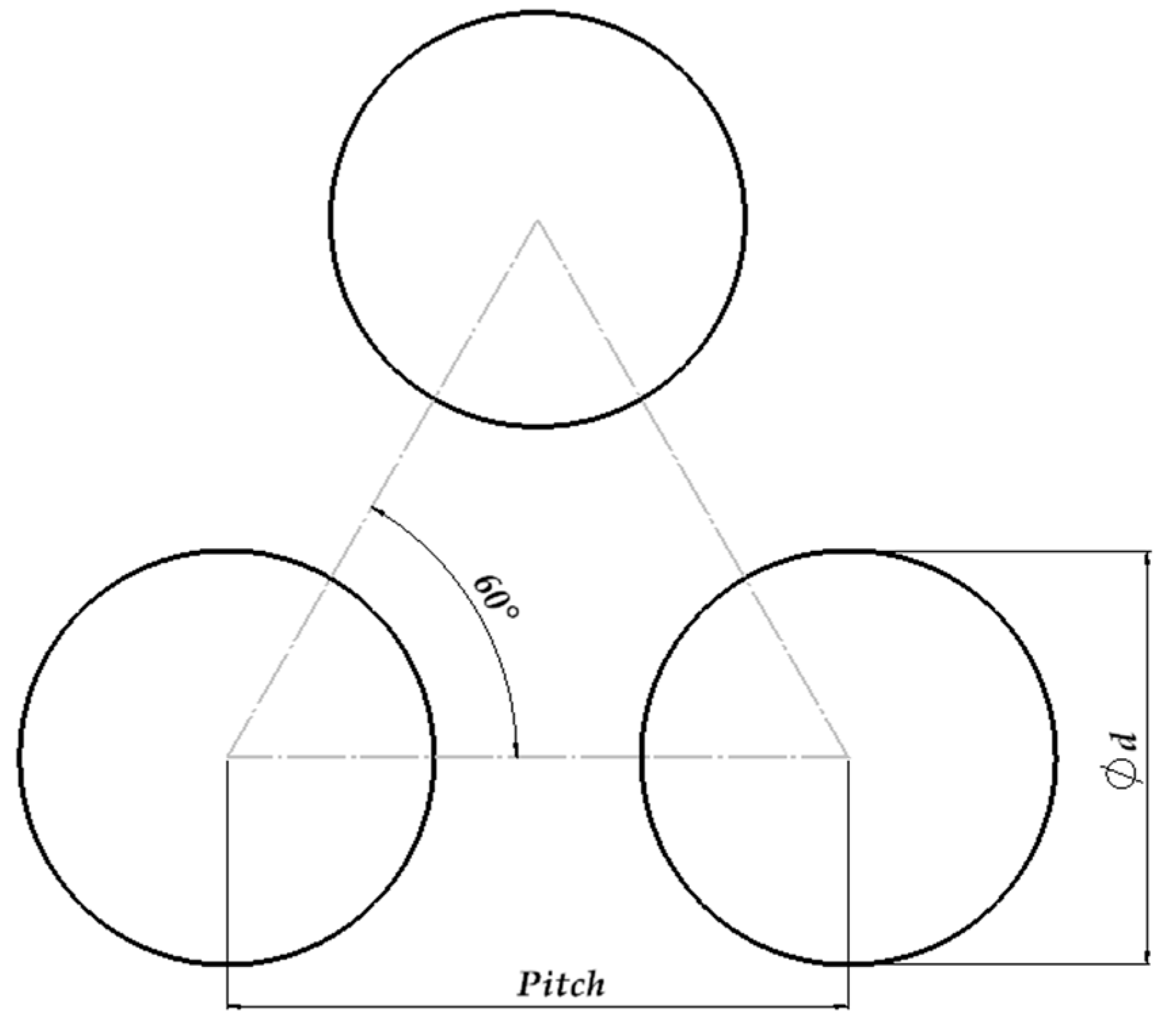
When the tube length is fixed, the number of tubes does not account for the tube diameter. The appropriate number of tubes for a 0.223 m shell diameter is determined based on the relationship between the tube’s outer diameter and the tube’s arrangement ratio [35,37]. A triangular arrangement, which allows for a greater number of tubes to be installed within the shell, was adopted; the corresponding constant values were applied accordingly [35]. Figure 3 shows a schematic of the triangular tube arrangement used in the heat exchanger configuration.
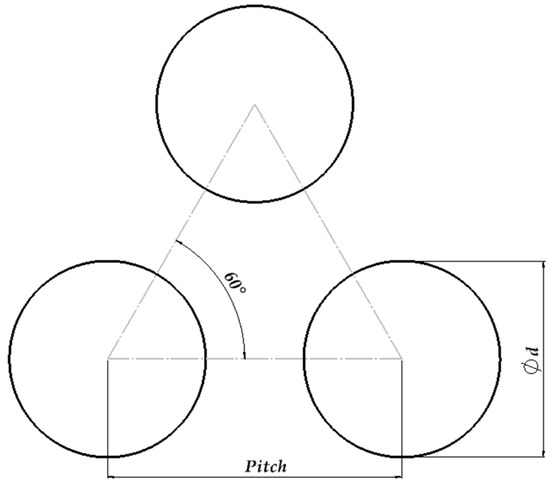
Figure 3.
A schematic diagram of a triangular tube layout showing the tube pitch and included angle.
The bundle diameter () was calculated by subtracting the shell diameter and the radial clearance () [34]. The relationship between bundle diameter and shell diameter, including radial clearance, was based on the empirical correlation presented in [37].
where
- is the bundle diameter (0.21 );
- are constants determined by the array format and number of passes ();
- is the radial clearance (0.013 ).
To satisfy the minimum clearance requirement, the tube pitch () was set to 1.25 times the tube’s outer diameter [35,37].
where
- is the tube’s pitch length ().
Calculations show that with a tube diameter of 3/4 in and a length of 0.6 m, the heat exchanger consists of 54 tubes, yielding a total heat transfer area of 1.94 m2. Compared to Table 7, the required heat transfer area is satisfied up to 15,000 ft; however, the heat transfer area is insufficient at altitudes above 20,000 ft. Therefore, a baffle design is required to increase heat transfer efficiency.
3.3. Design of Baffles
Baffles are designed to improve convective heat transfer on the shell side. The recommended baffle spacing is 0.2 to 1.0 times the shell diameter [35,37]. Exceeding this range can compromise structural durability, while smaller spacing can result in energy loss due to an excessive pressure drop [35,37]. In accordance with Mya et al. [42], who recommended a baffle cut of 0.25 times the shell diameter for an optimal balance between heat transfer enhancement and pressure drop, this study fixes the baffle cut ratio at 0.25 times the shell diameter and varies the baffle spacing at 0.25, 0.5, 0.75, and 1.0 times the shell diameter. The cross-sectional area of the flow through the tubes in the shell is calculated using Equation (35) [36,37].
where
- is the effective flow area between tubes ();
- is the tube’s pitch;
- is the baffle spacing ().
Equation (36) calculates the equivalent diameter () of the flow path on the shell. This value accounts for the non-circular flow area between tubes arranged in a triangular pitch [35,37].
where
- is the equivalent diameter in the shells ().
Equation (37) defines the velocity, which is calculated based on the air mass flow rate, density, and effective cross-sectional area between the tubes.
where
- is the airflow velocity in the shells ().
is the Reynolds number for the equivalent internal diameter of the shell. was calculated using Equation (22). Since the thermophysical properties of air remain constant, the from Table 7 is used.
The Nusselt numbers were corrected with the Colburn j factor (), where acts as a correction factor depending on the baffle cut. Detailed values of according to the baffle cut ratio are presented in Reference [37].
where
- is the Nusselt number in the shell;
- is the Colburn j factor with a baffle cut of 0.25.
The heat transfer coefficient was calculated using Equation (40).
where
- is the heat transfer coefficient of the shell.
3.4. Pressure Drop
The pressure drop was calculated to evaluate the performance of the shell-and-tube heat exchanger, as frictional losses and the resulting pressure drop increase the required pumping power. Equation (41) represents the pressure drop caused by the coolant on the tube side, and the friction factor () was obtained from Reference [37]. The coolant velocity is derived using Equation (37), after calculating the mass flow rate with Equation (13).
where
- is the pressure drop acting on the tube ();
- is the number of tube passes (1);
- is the friction factor of the tube;
- is the tube’s inner diameter ();
- is the tube’s flow rate ().
Equation (42) calculates the overall pressure drop across the shell, and the friction factor () was obtained from Reference [37].
where
- is the pressure drop acting on the shell ();
- is the shell friction coefficient;
- is the shell flow rate ().
3.5. System Efficiency
The required pumping power was quantitatively evaluated based on the pressure drop caused by the flow inside the heat exchanger. This allows for an evaluation of the overall pumping performance of the heat exchanger system and is used in the energy efficiency analysis of PEMFCs [43,44]. At this time, the system efficiency is assumed to be 0.75.
where
- is the system power ();
- is the fluid mass flow rate ();
- is the system efficiency (0.75).
The PEMFC system’s power that is available for propulsion is calculated by subtracting the power consumed by the heat exchanger, blower, and cooling water pump from the net PEMFC output. When the heat transfer of the heat exchanger is insufficient, additional electrical power is consumed to supplement the deficiency. Only the hydraulic power required to overcome the pressure drop in the heat exchanger is considered as the coolant pumping power.
where
- is the available power for propulsion ();
- is the PEMFC’s power ();
- is the power required for heat exchange ();
- is the blower power ();
- is the coolant pump power ();
- is the additional electrical power ().
4. Results
4.1. Heat Transfer Rate According to Baffle Configuration
Based on the heat transfer coefficient derived from Equation (40), the heat transfer rate was calculated for each baffle condition. Table 10 shows the convective heat flow according to altitude, tube diameter, and baffle spacing.
Table 10.
as a function of altitude and baffle spacing.
Compared to Table 5, the required convective heat transfer is satisfied at 20,000 ft and 25,000 ft even with the minimum baffle condition () whereas at 30,000 ft, a baffle spacing of 0.5 or less is required.
4.2. Calculation Results of Pressure Drop
Table 11 shows the pressure drop caused by the coolant on the tube side at each altitude. Table 12 shows the pressure drop according to the number of baffles in the shell at each altitude.
Table 11.
Pressure drop caused by the coolant on the tube side at each altitude.
Table 12.
Pressure drop caused by baffles on the shell side at each altitude.
4.3. Propulsion System Efficiency
Table 13 presents the pumping power on the tube side, while Table 14 shows the blower power on the shell side. Figure 4 compares the power loss of the PEMFC system with respect to the baffle spacing based on heat recovery and electrical output at each altitude (a = 20,000 ft; b = 25,000 ft; c = 30,000).
Table 13.
Tube side pump power.
Table 14.
Shell side blower power.
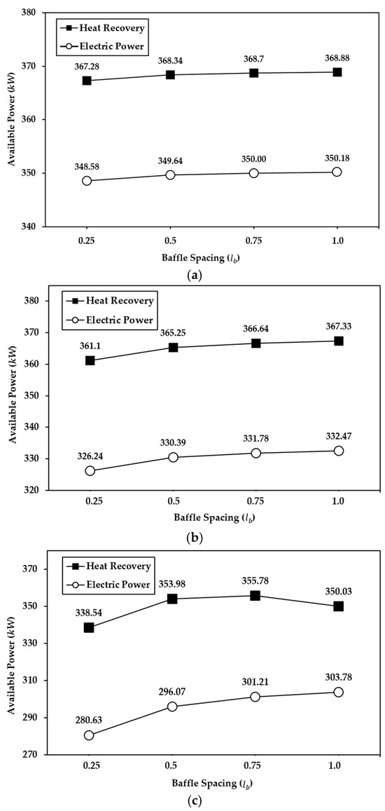
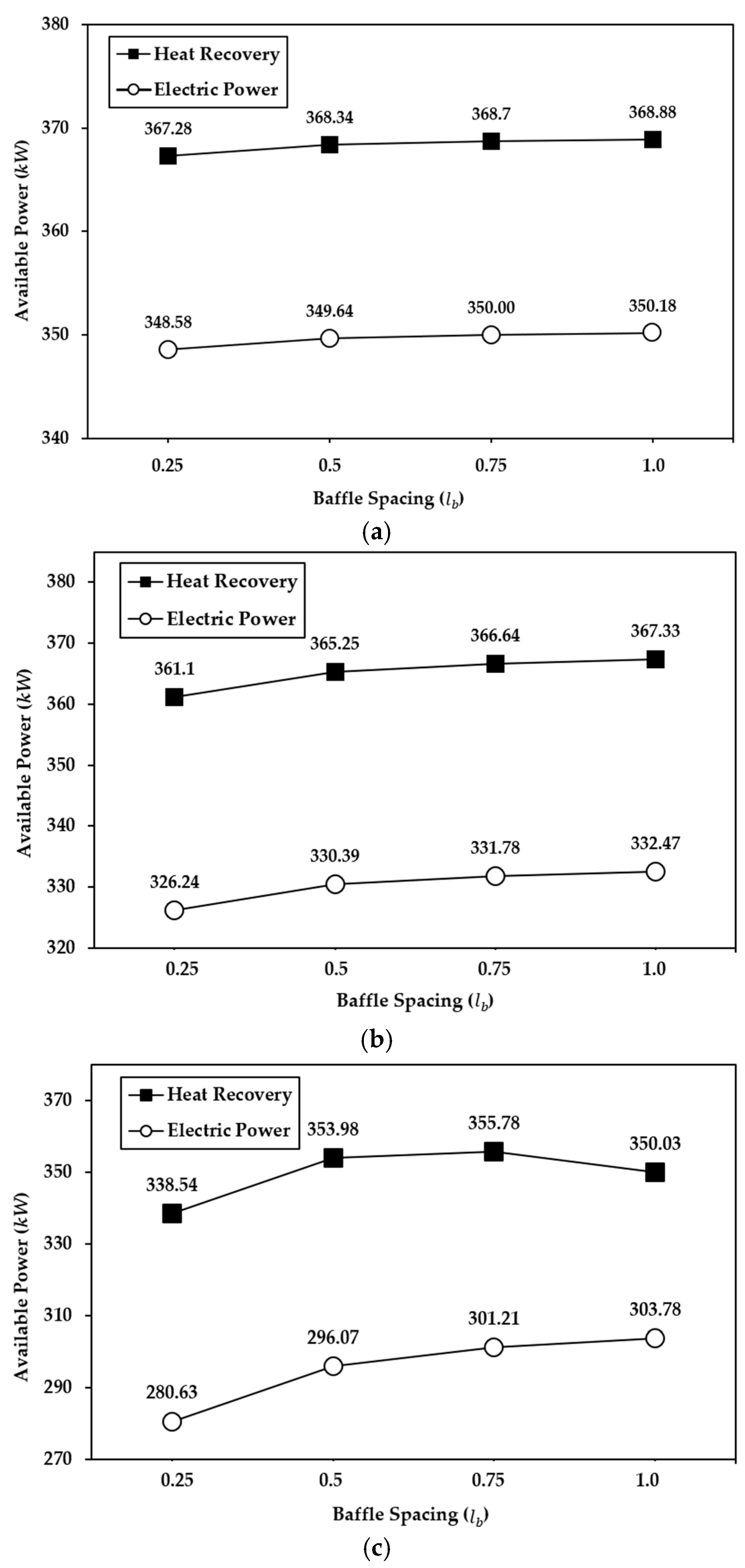
Figure 4.
Comparison of PEMFC system power loss as a function of baffle spacing, based on both heat recovery and electric power. (a) 20,000 ft, (b) 25,000 ft, (c) 30,000 ft.
Figure 4 demonstrates that the use of waste heat can effectively reduce the power consumption of the PEMFC system.
- Figure 4a shows that varying has almost no effect on the available system power when waste heat recovery is employed. Even when is reduced stepwise, the power loss remains below 0.3%, and the highest efficiency is reached when is 1.0. A power saving of approximately 5% is confirmed when compared to preheating the air using external power.
- Figure 4b shows a similar trend: when the value of is between 0.5 and 1.0, the available power changes little, but when is 0.25, there is a power penalty of about 1% compared to 0.5. In this case, preheating the intake air using waste heat lowers total power consumption by 5% compared to external electric preheating.
- Figure 4c reveals that when is 0.75 or 1.0, the required convective heat transfer is not fully achieved, resulting in additional electrical energy consumption. A noteworthy observation is that is 0.75 performs slightly better than is 0.5, suggesting proximity to an optimal threshold. Further fine-tuning around this value is necessary to precisely determine the optimal . When is 0.25, a power penalty of approximately 4.3% occurs relative to is 0.5. Compared to external electric preheating, the maximum power consumption is reduced by 15.7%.
- As altitude increases, the improvement in heat transfer efficiency enhances the effectiveness of waste heat recovery; however, the resulting increase in pressure drop may lead to the potential damage or performance degradation of the heat exchanger. In addition, inefficient baffle design can reduce the overall efficiency of the system, making the optimization of baffle spacing according to the required convective heat transfer essential.
5. Conclusions
In this study, a shell-and-tube waste heat recovery heat exchanger was designed to ensure the stable operation of the PEMFC in medium-altitude UAVs, and its thermal performance and pumping losses were quantitatively evaluated under various altitude conditions (15,000–30,000 ft). Due to the spatial constraints specific to UAV applications, the heat exchanger was designed with a diameter of 0.223 m and a length of 0.6 m. The resulting performance outcomes are presented as follows:
- As demonstrated in Reference [18], the incoming air to the PEMFC must be pre-heated to at least −5 °C to prevent MEA freezing and consequent performance degradation.
- The analysis showed that at 15,000 ft, the required heat transfer was achieved regardless of the presence of baffles; however, at altitudes of 20,000 ft and above, additional baffle design was necessary to compensate for insufficient heat transfer.
- The pressure drop was calculated by applying the minimum baffle configuration, and it was confirmed that the overall efficiency of the PEMFC system could be improved by up to 15.7%.
- As altitude increases, the required heat transfer also rises, necessitating a greater number of baffles. However, an increase in the number of baffles leads to higher pressure drop, which in turn reduces the efficiency of the power available for propulsion. To balance this trade-off, the waste heat recovery heat exchanger of a UAV-mounted PEMFC must be geometrically optimized for the altitude-dependent air properties required by the stack, ensuring that the preheated air remains above the freezing point and thereby preserving the efficiency of the MEA.
- Future work will focus on optimizing the heat exchanger geometry for each flight altitude, quantifying how waste heat recovery impacts PEMFC thermal management, and conducting three-dimensional simulations to obtain higher-fidelity thermal predictions. The analysis results will be used to quantify heat-transfer performance and pressure drop; icing tests will then be conducted, and the performance and reliability of the waste heat recovery system will be comprehensively evaluated.
Author Contributions
Conceptualization, J.J.; Methodology, J.J.; Validation, J.J.; Formal analysis, J.J.; Investigation, J.J.; Data curation, J.J.; Writing—original draft, J.J., J.C., S.-J.C. and S.-G.K.; Writing—review & editing, J.J.; Supervision, S.-G.K.; Project administration, S.-G.K.; Funding acquisition, S.-G.K. All authors have read and agreed to the published version of the manuscript.
Funding
This research was supported by a grant (RS-2023-00243094) from “Development of Safety Verification Technology for Small Aircraft with Hydrogen Fuel Cell-Based Propulsion System” Program funded by Ministry of Land, Infrastructure and Transport of Korean government and jointly supported by the Gyeonggi-do Regional Research Center (GRRC) program, funded by Gyeonggi province (GRRC Korea Aerospace University 2023-B04).
Data Availability Statement
The original contributions presented in this study are included in the article. Further inquiries can be directed to the corresponding author.
Acknowledgments
We gratefully acknowledge the support provided by the HEEP Laboratory at Korea Aerospace University.
Conflicts of Interest
The authors declare no conflict of interest.
References
- Khan, P.W.; Xu, G.; Latif, M.A.; Abbas, K.; Yasin, A. Uav’s Agricultural Image Segmentation Predicated by Clifford Geometric Algebra. IEEE Access 2019, 7, 38442–38450. [Google Scholar] [CrossRef]
- Panagiotou, P.; Tsavlidis, I.; Yakintkos, K. Conceptual design of a hybrid solar MALE UAV. Aerosp. Sci. Technol. 2016, 53, 207–219. [Google Scholar] [CrossRef]
- Gupta, P.; Pareek, B.; Singal, G.; Rao, D.V. Edge device based Military Vehicle Detection and Classification from UAV. Multimed. Tools Appl. 2022, 81, 19813–19834. [Google Scholar] [CrossRef]
- MQ-9 Reaper Specification. Available online: https://www.af.mil/About-Us/Fact-Sheets/Display/Article/104470/mq-9-reaper/ (accessed on 28 March 2025).
- KUS-FS Specification. Available online: https://aerospace.koreanair.com/business/uav/kusFs/ (accessed on 28 March 2025).
- Hermes 900 Specification. Available online: https://www.elbitsystems.com/autonomous/aerial/male-unmanned-aircraft-systems/hermes-900/ (accessed on 28 March 2025).
- RUSTOM-1 Specification. Available online: https://www.drdo.gov.in/drdo/rustom-1/ (accessed on 28 March 2025).
- Pan, Z.F.; An, L.; Wen, C.Y. Recent advances in fuel cells based propulsion systems for unmanned aerial vehicles. Appl. Energy 2019, 240, 473–485. [Google Scholar] [CrossRef]
- Hyun, D.; Han, H.; Hong, S. Development of hybrid-powered, sustainable multi-purpose drone system: An analysis model. Int. J. Hydrogen Energy 2024, 61, 762–773. [Google Scholar] [CrossRef]
- Cai, Q.; Brett, D.J.L.; Browing, D.; Brandon, N.P. A sizing-design methodology for hybrid fuel cell power systems and its application to an unmanned underwater vehicle. J. Power Sources 2010, 195, 6559–6569. [Google Scholar] [CrossRef]
- Donateo, T.; Ficarella, A.; Spedicato, L.; Arista, A.; Ferraro, M. A new approach to calculating endurance in electric flight and comparing fuel cells and batteries. Appl. Energy 2017, 187, 807–819. [Google Scholar] [CrossRef]
- Kim, Y.; Kang, S. Development of optimal energy management strategy for proton exchange membrane fuel cell-battery hybrid system for drone propulsion. Appl. Therm. Eng. 2025, 258, 124646. [Google Scholar] [CrossRef]
- Shen, Z.; Liu, S.; Zhu, W.; Ren, D.; Xu, Q.; Feng, Y. A Review on Key Technologies and Developments of Hydrogen Fuel Cell Multi-Rotor Drones. Energies 2024, 17, 4193. [Google Scholar] [CrossRef]
- Zeng, Z.; Bao, C.; Li, C.; Ouyang, M. A Modeling Study on Water and Thermal Management and Cold Startup of Unmanned Aerial Vehicle Fuel Cell System. eTransportation 2023, 15, 100222. [Google Scholar] [CrossRef]
- Zeroavia Flight Test. Available online: https://zeroavia.com/flight-testing/ (accessed on 14 March 2025).
- H2FLY History. Available online: https://h2fly.uber.space/company/ (accessed on 17 March 2025).
- Rajbongshi, B.M.; Saneeth, M.; Verma, A. Investigation on sub-zero start-up of polymer electrolyte membrane fuel cell using un-assisted cold start strategy. Int. J. Hydrogen Energy 2020, 45, 34048–34057. [Google Scholar] [CrossRef]
- Zhan, Z.; Yuan, C.; Hu, Z.; Wang, H.; Sui, P.C.; Djilali, N.; Pan, M. Experimental study on different preheating methods for the cold-start of PEMFC stacks. Energy 2018, 162, 1029–1040. [Google Scholar] [CrossRef]
- Wilberforce, T.; Olabi, A.G.; Muhammad, I.; Alaswad, W.; Sayed, E.T.; Abo-Khalil, A.G.; Maghrabie, H.M.; Elsaid, K.; Abdelkareem, M.A. Recovery of waste heat from proton exchange membrane fuel cells—A review. Int. J. Hydrogen Energy 2024, 52, 933–972. [Google Scholar] [CrossRef]
- Sheshpoli, M.A.; Ajarostaghi, S.S.M.; Delavar, M.A. Waste heat recovery from a 1180 kW proton exchange membrane fuel cell (PEMFC) system by Recuperative organic Rankine cycle (RORC). Energy 2018, 157, 353–366. [Google Scholar] [CrossRef]
- Antonio, C.S.; Lusia, A.J.; Lorenzo, N.C. Residual heat use generated by a 12 kW fuel cell in an electric vehicle heating system. Energy 2014, 68, 182–190. [Google Scholar]
- Xu, Z.; Yan, Y.; Wei, W.; Sun, D.; Ni, Z. Supply system of cryo-compressed hydrogen for fuel cell stacks on heavy duty trucks. Int. J. Hydrogen Energy 2020, 45, 12921–12931. [Google Scholar] [CrossRef]
- Lu, D.; Yi, F.; Li, J. Optimization of the Adaptability of the Fuel Cell Vehicle Waste Heat Utilization Subsystem to Extreme Cold Environments. Sustainability 2022, 14, 11570. [Google Scholar] [CrossRef]
- TPE331 Turboprop Engine Specifications. Available online: https://aerospace.honeywell.com/us/en/products-and-services/products/power-and-propulsion/engines/turboprop-engines/tpe331-turboprop-engine (accessed on 17 March 2025).
- Hesselgreaves, J.E. Compact Heat Exchangers: Selection, Design and Operation; Pergamon: Oxford, UK, 2001. [Google Scholar]
- Jin, Y.; Tang, G.H.; He, Y.L.; Tao, W.Q. Numerical Study of the Solid Particle Erosion on H-Type Finned Circular/Elliptic Tube Surface. Commun. Comput. Phys. 2017, 21, 466–489. [Google Scholar] [CrossRef]
- Han, J.; Kim, S.-J.; Lee, Y.-K.; Hur, D.-H. Chemical Cleaning of Magnetite Deposits on the Flow Mini-Channels of a Printed Circuit Heat Exchanger in an EDTA-Based Solution. Materials 2022, 15, 1471. [Google Scholar] [CrossRef]
- Fetuga, I.A.; Olakoyejo, O.T.; Abolarin, S.M.; Gbegudu, J.K.; Onwuegbusi, A.; Adelaja, A.O. Numerical analysis of thermal performance of waste heat recovery shell and tube heat exchangers on counter-flow with different tube configurations. Alex. Eng. J. 2023, 64, 859–875. [Google Scholar] [CrossRef]
- Cavcar, M. The International Standard Atmosphere (ISA); Anadolu University: Eskisehir, Turkey, 2000; Available online: http://fisicaatmo.at.fcen.uba.ar/practicas/ISAweb.pdf (accessed on 7 May 2025).
- Sutherland, W. The viscosity of gases and molecular force. Philos. Mag. 1893, 36, 507–531. [Google Scholar] [CrossRef]
- Beyond Aero Prototypes. Available online: https://www.beyond-aero.com/prototypes (accessed on 16 March 2025).
- O’Hayre, R.; Cha, S.W.; Collela, W.G.; Prinz, F.B. Fuel Cell Fundamentals, 3rd ed.; Wiley: Hoboken, NJ, USA, 2016; pp. 25–46. [Google Scholar]
- Graf, T.; Fonk, R.; Bauer, C.; Kallo, J.; Willich, C. Optimal Sizing of Fuel Cell and Battery in a Direct-Hybrid for Electric Aircraft. Aerospace 2024, 11, 176. [Google Scholar] [CrossRef]
- Rostami, M.; Dehghan Manshadi, M.; Afshari, E. Performance evaluation of two proton exchange membrane and alkaline fuel cells for use in UAVs by investigating the effect of operating altitude. Int. J. Energy Res. 2022, 46, 1481–1496. [Google Scholar] [CrossRef]
- Kern, D.Q. Process Heat Transfer; McGraw-Hill Book Company: New York, NY, USA, 1950. [Google Scholar]
- Abd, A.A.; Naji, S.Z. Analysis study of shell and tube heat exchanger for clough company with reselect different parameters to improve the design. Case Stud. Therm. Eng. 2017, 10, 455–467. [Google Scholar] [CrossRef]
- Towler, G.; Sinnott, R. Chemical Engineering Design: Principles, Practice and Economics of Plant and Process Design, 3rd ed.; Butterworth-Heinemann: Oxford, UK, 2013. [Google Scholar]
- Patel, V.K.; Rao, R.V. Design optimization of shell-and-tube heat exchanger using particle swarm optimization technique. Appl. Therm. Eng. 2010, 30, 1417–1425. [Google Scholar] [CrossRef]
- Abd, A.A.; Kareem, M.Q.; Naji, S.Z. Performance analysis of shell and tube heat exchanger: Parametric study. Case Stud. Therm. Eng. 2018, 12, 563–568. [Google Scholar] [CrossRef]
- Gnielinski, V. Neue Gleichungen für den Wärme-und den Stoffübergang in turbulent durchströmten Rohren und Kanälen. Forsch. Im Ingenieurwesen 1976, 42, 145–153. [Google Scholar] [CrossRef]
- Lee, P.S.; Garimella, S.V.; Liu, D. Investigation of heat transfer in rectangular microchannels. Int. J. Heat Mass Transf. 2005, 48, 1688–1704. [Google Scholar] [CrossRef]
- Mya, N.S.; Thu, M.M.; Htwe, S.N.C.; Oo, M.P.S.; Htay, M.K.S.; Htet, M.N.L. Baffle Design of Shell And Tube Heat Exchanger. Int. J. Sci. Eng. Technol. Res. 2019, 8, 420–426. [Google Scholar]
- Azad, A.V.; Amidpour, M. Economic optimization of shell and tube heat exchanger based on constructal theory. Energy 2011, 36, 1087–1096. [Google Scholar] [CrossRef]
- Selbaş, R.; Kızılkan, Ö.; Reppich, M. A new design approach for shell-and-tube heat exchangers using genetic algorithms from economic point of view. Chem. Eng. Process. Process Intensif. 2006, 45, 268–275. [Google Scholar] [CrossRef]
Disclaimer/Publisher’s Note: The statements, opinions and data contained in all publications are solely those of the individual author(s) and contributor(s) and not of MDPI and/or the editor(s). MDPI and/or the editor(s) disclaim responsibility for any injury to people or property resulting from any ideas, methods, instructions or products referred to in the content. |
© 2025 by the authors. Licensee MDPI, Basel, Switzerland. This article is an open access article distributed under the terms and conditions of the Creative Commons Attribution (CC BY) license (https://creativecommons.org/licenses/by/4.0/).