Article

Space Vector Modulation Methods with Modified Zero Vector Distribution for Electrical Vehicle Drives with Six-Phase Induction Motor Operating Under Direct Field-Oriented Control

Department of Electrical Machines, Drives and Measurements, Faculty of Electrical Engineering, Wroclaw University of Science and Technology, 19 Smoluchowskiego St., 50-372 Wroclaw, Poland
*
Author to whom correspondence should be addressed.
Energies 2025, 18(12), 3122; https://doi.org/10.3390/en18123122
Submission received: 11 May 2025 / Revised: 1 June 2025 / Accepted: 11 June 2025 / Published: 13 June 2025
(This article belongs to the Special Issue Drive System and Control Strategy of Electric Vehicle)

Abstract

:
This paper presents a Space Vector Modulation (SVM) method with a novel zero vector distribution system for electrical vehicle drives with a six-phase induction motor working under the Direct Field-Oriented Control (DFOC) method. Different SVM methods are described and compared, and a new approach with long vectors only and a special zero vector distribution, that compensates for the third harmonic component is proposed. The DFOC method is described and the influence of the applied modulation method on six-phase motor currents is shown. Results of our experimental studies on the DFOC method are presented and discussed. The proposed modulation method for a six-phase Voltage Source Inverter can be applied in fault-tolerant electrical vehicles.

1. Introduction

Conventional three-phase squirrel-cage induction motors are commonly used in electrical vehicles [1,2] and industrial drive systems [3,4]. However, three-phase motors are not characterized by high operating reliability, since an interruption even in only one phase of the stator winding eliminates the possibility of the further operation of the motor. In recent years there has been a great interest in using squirrel-cage induction motors with more than three stator phases. Motors of this design are called multi-phase induction motors [5,6,7].
These multi-phase motors ensure the greater reliability of drive system operation [7,8]. Greater reliability is connected with the possibility of operating the motor conditionally even if one of the inverter or motor phases is damaged. Moreover, the motor phase currents are smaller compared to a three-phase motor when the same motor power and voltage are considered. Additionally, the higher harmonic components of motor currents and DC-link current are reduced.
Due to these properties, multi-phase machines are used in electric vehicles since they require high reliability [5,9]. Moreover, they can be applied in electrical traction systems [10,11], wind power systems [12,13] and battery chargers [14,15].
Multi-phase motors can have different stator winding designs. In the scientific literature and in practical applications there are examples of multi-phase motors with symmetrical distributions of their phase axes, for example, five-phase [6,16,17], six-phase [6,18,19], seven-phase [20], nine-phase [14] and even fifteen-phase induction motors [21]. Motors with double stator winding [22,23,24] and motors with open-end stator winding [25] have also been analyzed. In this article a six-phase induction motor with symmetrical phase-axis distribution will be analyzed. In six-phase motors it is possible to use a single-star stator winding connection or a double-star stator winding connection, which have been analyzed in various articles [6,8]. In this paper both solutions are considered, but with an emphasis on the single-star connection due to its greater reliability and resistance to stator phase failures. However, it is a more difficult solution for stator voltage modulation methods.
In drive systems with six-phase motors, similarly to three-phase motors, the DFOC [6,8,22], DTC-ST [8,26] and DTC-SVM [20] vector control methods are used. Both of the most commonly used control methods—DFOC and DTC-SVM—require voltage modulation. There are many modulation methods that can be adapted from three-phase modulation principles to multi-phase control schemes, for example, sinusoidal and current tracking modulation [17,22], but vector modulation seems to be the natural choice, because DFOC and DTC-SVM control structures define the refence voltage vector with two components directly. There are only a few articles on the various Space Vector Modulation methods for symmetrical six-phase motors with a common neutral point. They present the known solution for three-phase systems when using only long voltage vectors [18,19,27] and a novel approach using medium vectors only [18,19]. All of them show that when using only long vectors, additional voltage components appear and make the voltage and current significantly distorted. Therefore, the usage of medium vectors only is proposed. However, this makes the voltage that can be obtained limited. Moreover, the mentioned papers lack the analysis of higher harmonics, there are no fundamental frequency amplitude characteristics presented, and they include only simulation test results. Additionally, analysis of the conversion of voltage vectors into duty cycles is missing.
In this paper, particular attention is paid to modulation methods with long vectors, which provide the highest possible voltage and longest linear modulation range. The novelty of this paper is in its Space Vector Modulation algorithm with long voltage vectors only and modified zero vector distribution, considering zero vectors other than the two basic ones. Moreover, the paper focusses on the comparison of modulation methods with vectors of different lengths: long, medium and short. Theoretical analysis, experimental studies and a comparison of four vector modulation methods for a six-phase voltage inverter are conducted. The tests were carried out within a DFOC structure. Detailed characteristics of the fundamental component and low-order higher harmonics are presented as well.
The paper is organized as follows. First, in Section 2 the mathematical model of the six-phase squirrel-cage induction motor is presented. Then, in Section 3 the mathematical model of the six-phase VSI is described. The experimental setup is presented in Section 4. Section 5 deals with the description of the DFOC method. The SVM methods are discussed in Section 6. Section 7 is dedicated to the description of the duty cycle approach. The experimental results are presented and discussed in Section 8 and modulation characteristics are presented and discussed in Section 9. Section 10 is dedicated to the concluding remarks.

2. Mathematical Model of Six-Phase Squirrel-Cage Induction Motor

The mathematical model of a six-phase squirrel-cage induction motor is formulated based on commonly used simplifying assumptions presented in detail in [8,20,22]. The mathematical model is described by a system of differential equations in which the values of the mutual induction coefficients are variable as functions of the rotor rotation angle. In order to eliminate this inconvenience, the transformation of the motor phase variables is carried out using a transformation matrix.
The transformation matrix C transforms the phase variables into the variables denoted by subscripts α and β, expressed in a coordinate frame stationary with respect to the stator winding; subscripts z1 and z2, expressed in the additional coordinate system; and zero variables, denoted by subscripts 01 and 02. The transformation matrix C must be a square matrix whose number of rows and columns is equal to the number of motor phases. It can be formulated in various ways. In this paper the following matrix C is assumed [28]:
u s α u s β u s z 1 u s z 2 u s 01 u s 02 = C u s A u s B u s C u s D u s E u s F = 2 n 1 cos α cos 2 α cos 3 α cos 4 α cos 5 α 0 sin α sin 2 α sin 3 α sin 4 α sin 5 α 1 cos 2 α cos 4 α cos 6 α cos 8 α cos 10 α 0 sin 2 α sin 4 α sin 6 α sin 8 α sin 10 α 1 / 2 1 / 2 1 / 2 1 / 2 1 / 2 1 / 2 1 / 2 1 / 2 1 / 2 1 / 2 1 / 2 1 / 2 u s A u s B u s C u s D u s E u s F
where n is the number of motor phases, n = 6; α = 2π/n; usA, …, usF are motor phase voltages; u and u are components of the stator voltage vector in the αβ system; usz1 and usz2 are components of the stator voltage vector in the z1z2 frame; and us01 and us02 are components of the stator voltage vector in the 01–02 frame.
The general equations of the six-phase induction motor, expressed in the transformed coordinate systems are presented below [8,23]:
-
The stator and rotor voltage equations in the αβ coordinate system:
u s α = R s i s α + p ψ s α
u s β = R s i s β + p ψ s β
0 = R r i r α + p ψ r α + ω e ψ r β
0 = R r i r β + p ψ r β ω e ψ r α
-
The stator voltage equations in the additional coordinate system z1z2:
u s z 1 = R s i s z 1 + p ψ s z 1 = R s i s z 1 + L l s p i s z 1
u s z 2 = R s i s z 2 + p ψ s z 2 = R s i s z 2 + L l s p i s z 2
-
The stator voltage equations in the 01–02 coordinate system:
u s 01 = R s i s 01 + p ψ s 01 = R s i s 01 + L l s p i s 01
u s 02 = R s i s 02 + p ψ s 02 = R s i s 02 + L l s p i s 02
-
The equation of the electromagnetic torque:
T e = n 2 p p L m L r ψ r α i s β ψ r β i s α
where p is the Laplace operator (derivative); i and i are components of the stator current vector in the αβ system; i and i are components of the rotor current vector in the αβ system; ψ, ψ, ψ and ψ are components of the stator and rotor flux vector in the αβ coordinate system; isz1 and isz2 are components of the stator current vector in the z1z2 frame; is01 are is02 components of the stator current in the 01–02 frame; ψsz1 and ψsz2 are components of the stator flux vector in the z1z2 frame; ψs01 are ψs02 are components of the stator flux vector in the 01–02 frame; ωe is the electrical angular speed of the rotor; Te is the electromagnetic torque; Rs and Rr are the stator and rotor phase resistance; Lm is the magnetization inductance; Lr = Lm + Lrl gives the total inductance of the rotor winding; Ls = Lm + Lsl gives the total inductance of the stator winding; Lsl and Lrl are the stator and rotor leakage inductance; and pp is the number of pole pairs.

3. Mathematical Model of Six-Phase Voltage Source Inverter

A block diagram of a six-phase Voltage Source Inverter (VSI) is shown in Figure 1. Figure 1a shows the converter connected to a six-phase induction motor stator winding using the single-star topology when the neutral point is common for all phases. Figure 1b shows the double-star topology with two neutral points, N1 and N2.
Depending on the winding connection type, shown in Figure 1, the phase voltages vary as shown in (11)—the matrix’s left part indicates the single-star topology, while the right part indicates the double-star connection [11]. This difference will be visible in the voltage vectors generated.
u s A u s B u s C u s D u s E u s F = u A N u B N u C N u D N u E N u F N = u d 6 5 1 1 1 1 1 1 5 1 1 1 1 1 1 5 1 1 1 1 1 1 5 1 1 1 1 1 1 5 1 1 1 1 1 1 5 S A S B S C S D S E S F u s A u s B u s C u s D u s E u s F = u A N 1 u B N 2 u C N 1 u D N 2 u E N 1 u F N 2 = u d 3 2 0 1 0 1 0 0 2 0 1 0 1 1 0 2 0 1 0 0 1 0 2 0 1 1 0 1 0 2 0 0 1 0 1 0 2 S A S B S C S D S E S F
where SA…F are the switching signals of the inverter legs; S = 1 when the upper switch of the inverter leg is on and S = 0 when the lower switch is on; and ud is the voltage of the DC bus of the inverter.
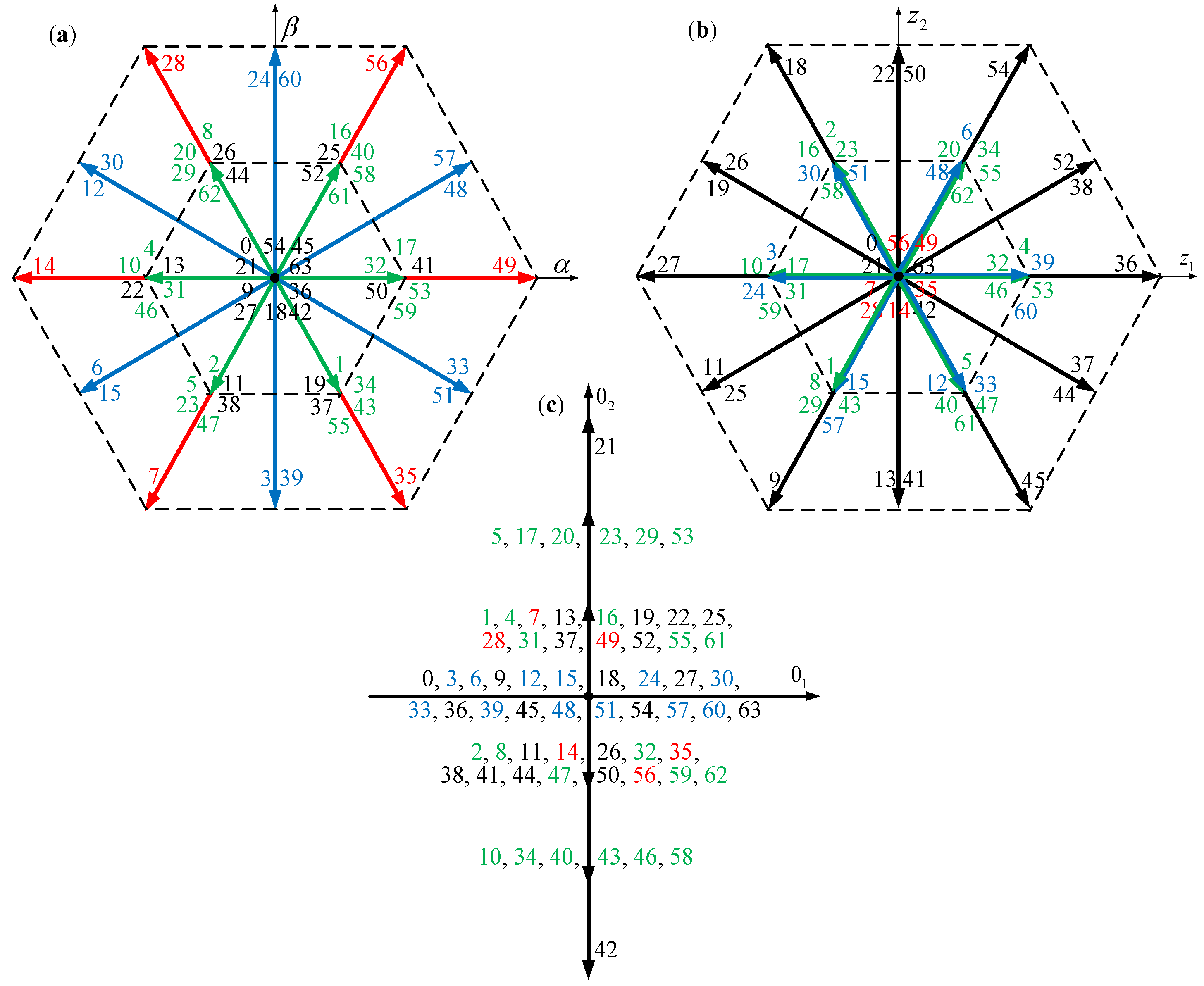
The six-phase VSI generates a system of six-phase voltages on the AC side, which can be represented by the corresponding stator voltage vectors in selected coordinate systems, calculated with (1). Figure 2 shows the sets of stator voltage vectors generated by the six-phase VSI for different combinations of conduction states of the inverters power electronics switches [18,19,28]. The number of possible states is equal to 2n = 64. Figure 2a shows voltage vectors in the αβ coordinate system, Figure 2b shows the voltage vectors in the additional z1z2 coordinate system and Figure 2c shows the 01–02 coordinate system. In the figures, the numbering of the individual voltage vectors by consecutive numbers in the decimal system is adopted. Each decimal number specifying the voltage vector number can be converted into a six-position number in the binary system. The consecutive bits of the binary number determine the logical values corresponding to the states of the individual branch switches of the VSI.
As can be seen in Figure 2a, the generated vectors in the αβ frame amplitudes can be long (marked in red), medium (marked in blue), short (green) or zero (black). All the lengths of the vectors are gathered in Table 1.
All the long vectors have zero z1z2 components but non-zero short amplitudes in the 01–02 frame. On the other hand, the medium vectors have short amplitudes in the z1z2 frame, but zero 01–02 components. The short vectors have short amplitudes in the z1z2 frame but can have short or medium amplitudes in the 01–02 frame. Zero vectors in the αβ frame can have zero, medium or long amplitudes in the z1z2 frame. Only two vectors are zero in all frames: 0 and 63. Only two more zero vectors also have zero amplitudes in the z1z2 frame: 21 and 42. However, they are the only vectors with long amplitudes in the 01–02 frame.
The difference between the single-star and double-star topology is simple—in the case of the double-star connection, all 01–02 frame vectors disappear, while the rest of the vectors is invariant. Thus, the voltage modulation is more difficult in the case of the single-star topology, therefore this case is analyzed further in the paper.
According to (10) the electromagnetic torque in multi-phase motors is generated only with the usαβ vector. However, the action of the stator voltage vectors usz1z2 and us0102 should be considered in the analysis, since these voltage vectors force the flow of additional phase current components in the stator winding. These components can cause an increase in the amplitudes of the stator phase currents and thus increase the electrical power losses.

4. Experimental Setup

The experimental setup was equipped with a six-phase induction motor of 1.5 kW, specially rewound from a 3-phase Besel Sh 90-4L industrial motor (Brzeg, Poland). Its parameters are given in Appendix A.
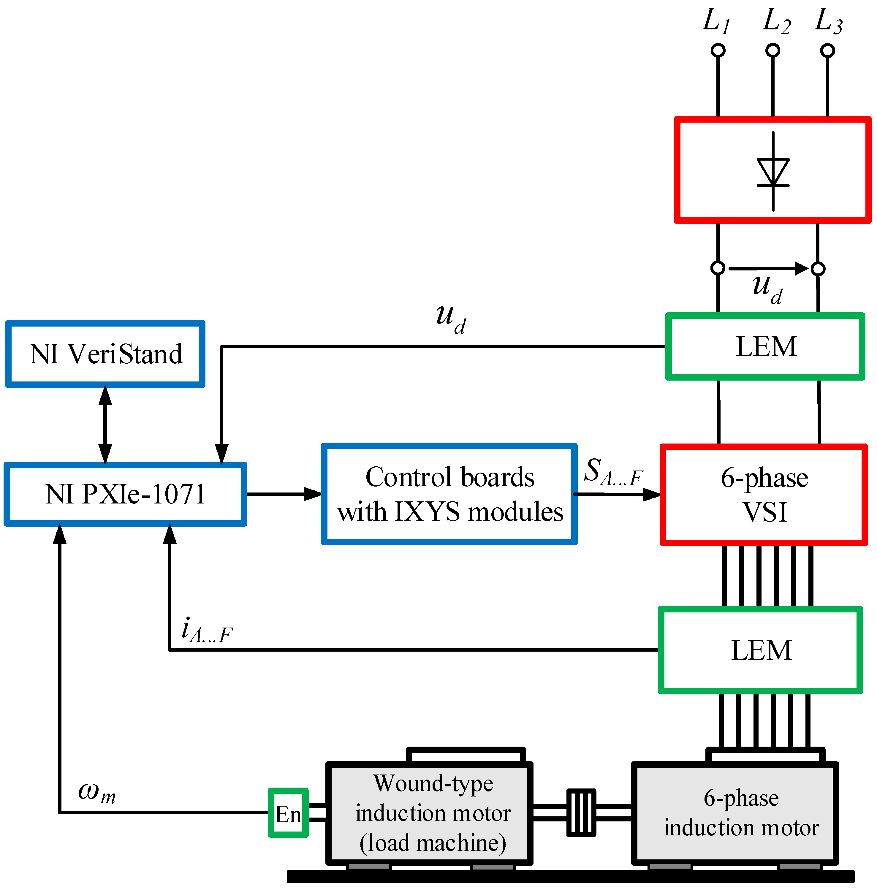
The motor was supplied from a specially designed 6-phase IGBT-based VSI. Each switch of the inverter was controlled with fiber optics so that galvanic isolation was ensured. The hardware dead-time was ensured by two IXYS modules. In order to generate the load torque, another, wound-type induction motor (Indukta, Indukta SZUe 24b, Cieszyn, Poland) was used. The rapid prototyping unit NI PXIe-1071 with an NI PXIe-8840 Quad Core RT processor and an FPGA NI PXI-7851R R Series card were used. NI VeriStand 2021 R3 and MATLAB-Simulink 2020b software were used to prototype and verify the control structure and modulation methods, as well as to acquire the experimental data.
The speed was measured using an incremental encoder from Kübler 8.5020.8844.3600 with 3600 imp/rev. The DC voltage and 6-phase currents were measured by LEM transducers. A block diagram of the experimental setup is presented in Figure 3.

5. Direct Field-Oriented Control System

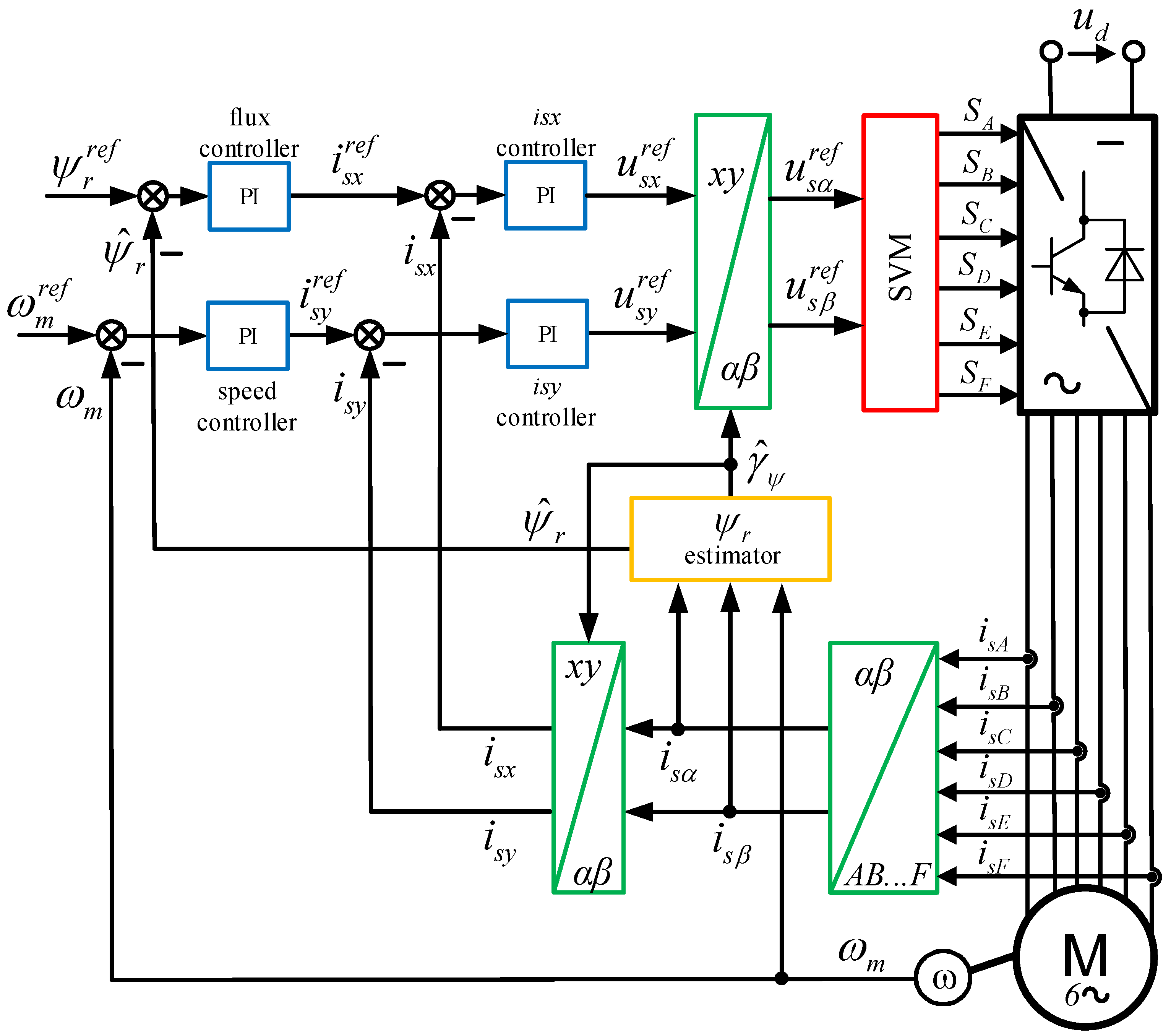
The Direct Field-Oriented Control (DFOC) method for six-phase squirrel-cage induction motors is considered in [6,8,22]. A diagram of the control system is shown in Figure 4.
Two outer control loops with PI controllers are applied in this control structure: the control loop of the motor speed and the control loop for the magnitude of the rotor flux vector. The controller of the angular speed defines the torque-producing current (the y-axis component of the stator current vector). The rotor flux controller defines the flux-producing current (the x-axis component of the stator current vector). Two inner current control loops are responsible for ensuring that the reference values of the x and y current components are equal to their measured equivalents. Reference values of the stator voltage vector components are transformed to the αβ coordinate system using the inverse Park transformation and further used by the Space Vector Modulation (SVM) block. The SVM determines the switching states of the six-phase VSI. An estimator of the rotor flux vector, based on the stator phase currents and motor speed, is applied in this control system.
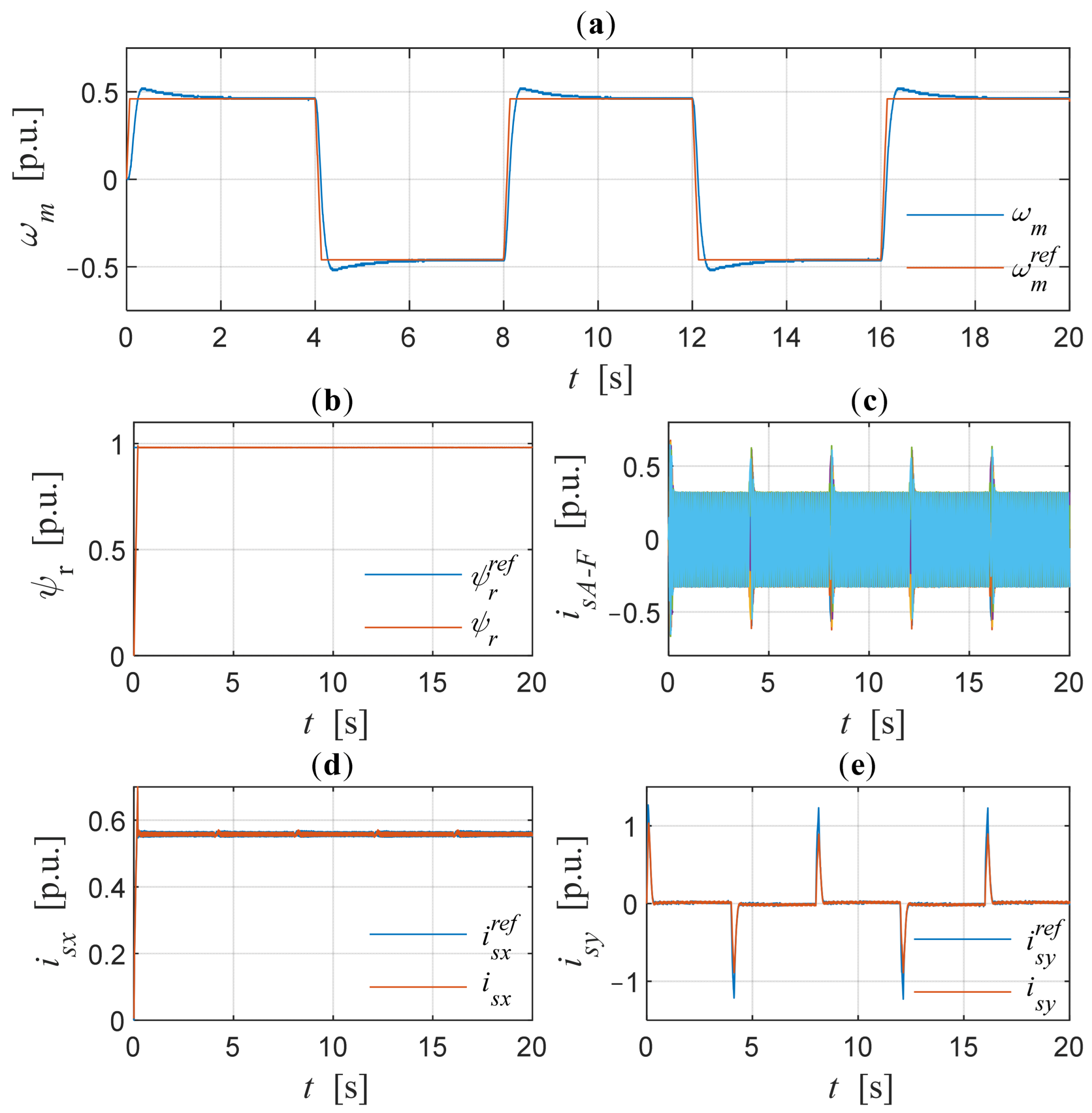
The experimental studies of the DFOC of the six-phase induction motor included rapid changes in the reference motor speed (Figure 5). It can be stated that the real speed follows the reference one with a small overregulation and without any steady-state errors. Thus, the analyzed method provides fast and accurate control of the motor speed (Figure 5a).
The magnitude of the rotor flux vector reaches the set value in a very short time, and during the speed changes the rotor flux vector maintains its value at a constant level. This is shown in Figure 5b. The rotor flux amplitude is controlled by the x-axis stator current component. It is constant during the control process as well (Figure 5d).
In order to change speed rapidly, the y-axis stator current component reaches high values during speed reversals, as shown in Figure 5e. Its changes correspond to changes in motor phase currents (Figure 5c).

6. Space Vector Modulation Methods

6.1. Classical Space Vector Modulation Method (Only Long Vectors and Two Different Zero Vectors)

Since the long vectors (7, 14, 28, 35, 49, 56) are identical to those in the case of a three-phase system, the same SVM strategy could be used in the case of a six-phase system, assuming traditional zero vector (0, 63) usage [18,19,27]. However, this can be justified only when the double-star winding topology is used. Otherwise, 01–02 vector components appear and low-order higher harmonics are generated in both the voltage and phase currents (as will be shown in the following section). It should be noted that when using only long vectors and these two zero vectors the z1z2 components are always eliminated.
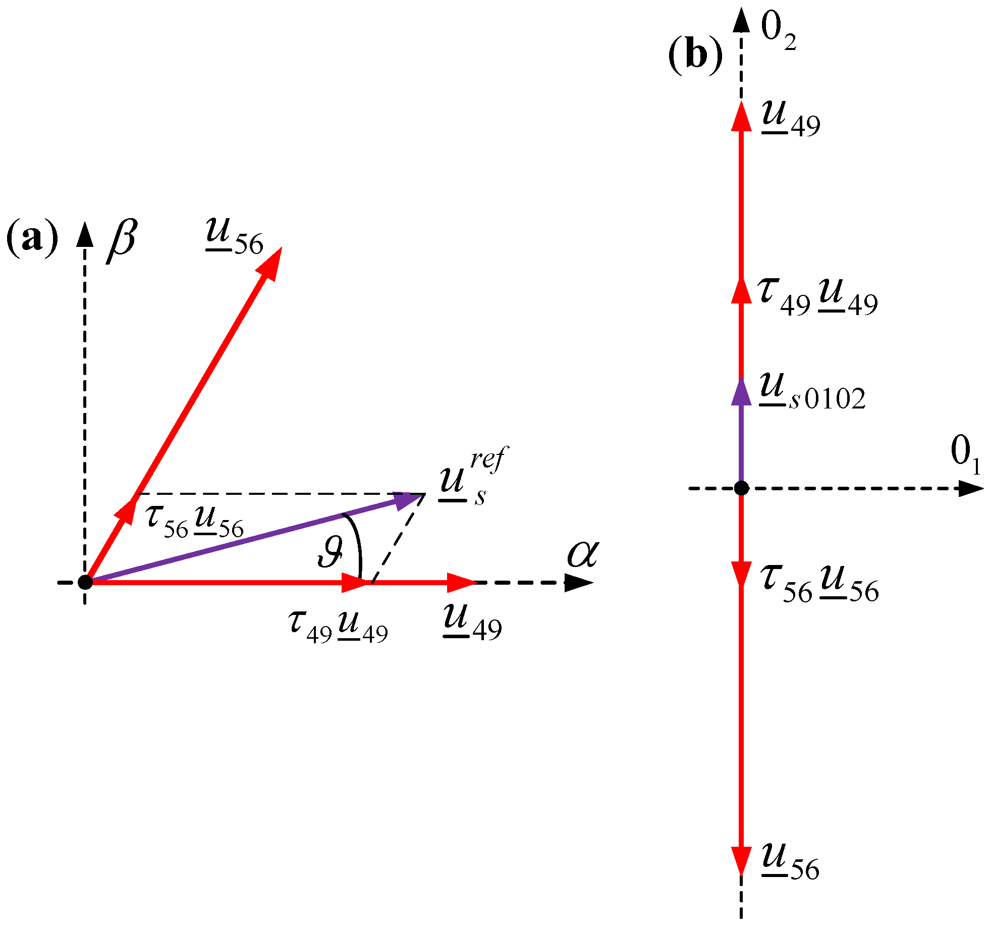
In this case the reference stator voltage vector u ¯ s r e f is synthesized using only two long voltage vectors, located in the corresponding sector, and two zero voltage vectors. In the modulation algorithm, six sectors are defined, with the angles between neighboring vectors equal to π/3. An example of SVM operation is shown in Figure 6. Sector number 1 is presented in Figure 6a; hence, the long vectors 49 and 56 are used. The reference vector is obtained by applying vector 49 for time τ49 and vector 56 for time τ56. The remaining time must be divided into zero vectors. In most cases the symmetrical approach is applied, and the vectors are distributed to half of the switching time Ts each.
In the presented example for sector 1, the synthesis of the reference vector can be described by the following equation:
u ¯ s r e f = u ¯ 0 τ 0 + u ¯ 49 τ 49 + u ¯ 56 τ 56 + u ¯ 63 τ 63
Thus, the times are given by
τ 49 = 3 u ¯ s r e f u d sin π / 3 ϑ τ 56 = 3 u ¯ s r e f u d sin ϑ τ 0 = τ 63 = 1 τ 49 τ 56 / 2
where τ = t/Ts is the normalized time and ϑ is the angle of the reference stator voltage vector towards vector u ¯ 49 . The example (13) is presented for sector 1. However, the remaining voltage sectors are calculated in a similar manner.
As was mentioned before, the z1z2 components are zero, since only long vectors are used. Figure 6b shows the 01–02 components of the generated stator voltage when the single-star topology is used. Although vectors 49 and 56 have the same amplitudes and opposite directions, the components are not balanced over the switching period since their times are different. In the case of the double-star topology, the components are zero.

6.2. Vector Modulation Method for Six-Phase VSI Using Medium Vectors

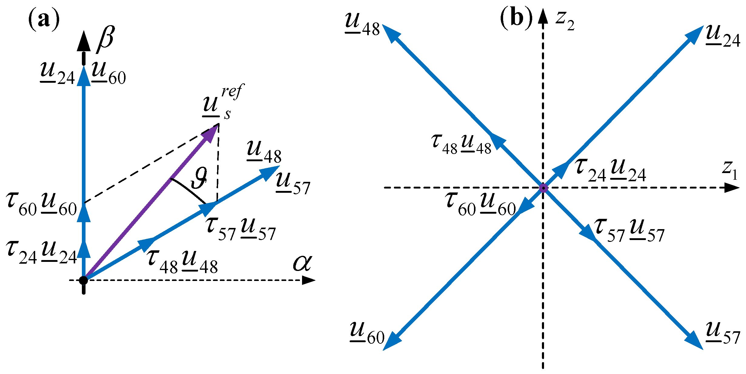
The drawback of the SVM method adapted from three-phase systems, described in the previous section, is the generation of low-order higher harmonics due to the non-balanced 01–02 components. To minimize their content in the output voltage, the usage of only medium vectors (48, 57, 24, 60, 12, 30, 6, 15, 3, 39, 33, 51) is proposed in [18,19]. The synthesis of the reference voltage in the αβ frame is like the traditional SVM described in Section 6.1 and the number of the voltage sectors is similar, equal to six. The angle of each sector is the same, but the sectors are distributed in a different way. For example, sector 1 is shown in Figure 7a, and it extends from an angle of 30 degrees to 90 degrees. The zero vectors used are also the same, 0 and 63.
Using medium vectors only, the z1z2 components are present in the voltage, as shown in Figure 2b. Therefore, a special sequence must be defined; i.e., the two vectors with the same αβ coordinates must be applied for the same time to balance the z1z2 components, as shown in Figure 7b. In this example vector τ 48 u ¯ 48 is compensated by τ 57 u ¯ 57 and τ 24 u ¯ 24 is compensated by τ 60 u ¯ 60 .
Thus, in this modulation method the required stator voltage vector is synthesized using four medium voltage vectors located in the corresponding sector and two zero voltage vectors. The selected voltage vectors used to implement the SVM algorithm in sector 1 are shown in Figure 7.
The modulation algorithm is described by the following equation:
u ¯ s r e f = u ¯ 0 τ 0 + u ¯ 24 τ 24 + u ¯ 60 τ 60 + u ¯ 48 τ 48 + u ¯ 57 τ 57 + u ¯ 63 τ 63
where times are calculated as
τ 24 = τ 60 = 3 3 u ¯ s r e f u d sin π / 3 ϑ τ 48 = τ 57 = 3 3 u ¯ s r e f u d sin ϑ τ 0 = τ 63 = 1 τ 24 τ 60 τ 48 τ 57 / 2
The 01–02 components are eliminated if only medium voltage vectors are used, as is shown in Figure 2c.

6.3. Modified Space Vector Modulation Method Using Long and Four Zero Voltage Vectors

In this paper we propose modifying classical SVM with only long vectors by using a different distribution of the zero vectors. In a traditional approach only two vectors (0, 63) are applied, while in this new approach two more zero vectors are applied (21, 42). Only these four zero vectors guarantee that the αβ and z1z2 components are zero.
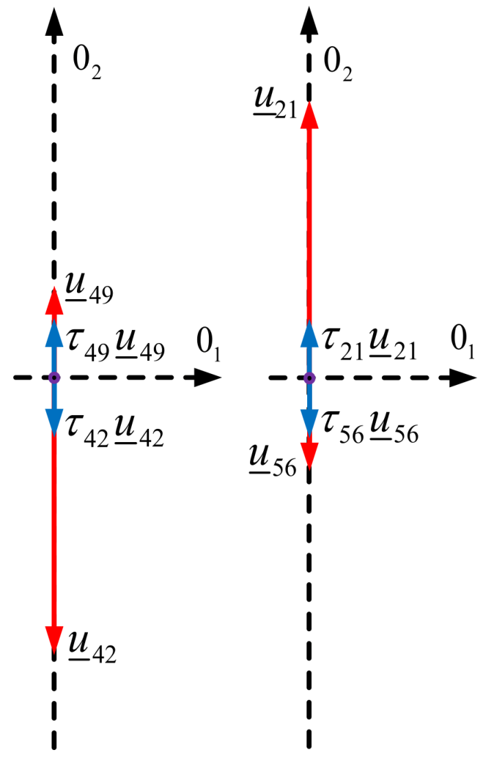
The reference voltage in αβ is synthetized with the same long vectors as described in Section 6.1 and Figure 6a. The voltage components in z1z2 frame are always zero, as shown in Figure 2b. However, the 01–02 components appear as mentioned in Section 6.1. In order to compensate for the 01–02 components, two additional zero vectors are applied. The application of this idea to sector 1 is shown in Figure 8—vector τ 49 u ¯ 49 is geometrically opposite to vector τ 21 u ¯ 21 (similarly, vector τ 56 u ¯ 56 should be compensated by τ 42 u ¯ 42 ). Since the amplitude of the u ¯ 21 vector is three times longer than the amplitude of the u ¯ 49 vector in the 01–02 frame, the following zero voltage vector distribution is defined:
τ 21 = τ 49 / 3 τ 42 = τ 56 / 3 τ 0 = τ 63 = 1 τ 21 τ 42 / 2
The proposed modulation algorithm is described by the following formula:
u ¯ s r e f = u ¯ 0 τ 0 + u ¯ 21 τ 21 + u ¯ 49 τ 49 + u ¯ 56 τ 56 + u ¯ 42 τ 42 + u ¯ 63 τ 63
When the reference voltage value increases, the required times of zero vector (16) can be longer than the remaining time in the Ts period reserved for zero vector τ z e r o . Thus, the new zero vectors can no longer be large enough to compensate for the long vectors in 01–02 frame. In this case, i.e., when τ 21 + τ 42 > τ z e r o , it is proposed to distribute the times in a symmetrical way:
τ 21 = τ 21 / τ 21 + τ 42 τ z e r o τ 42 = τ 42 / τ 21 + τ 42 τ z e r o τ 0 = τ 63 = 0

6.4. Space Vector Modulation Method Using Short and Zero Voltage Vectors

If the reference voltage vector becomes short, intuitively, it can be assumed that the usage of short vectors can provide better-quality motor voltage and currents in terms of the generated higher harmonics. Therefore, this opportunity is evaluated in this section.
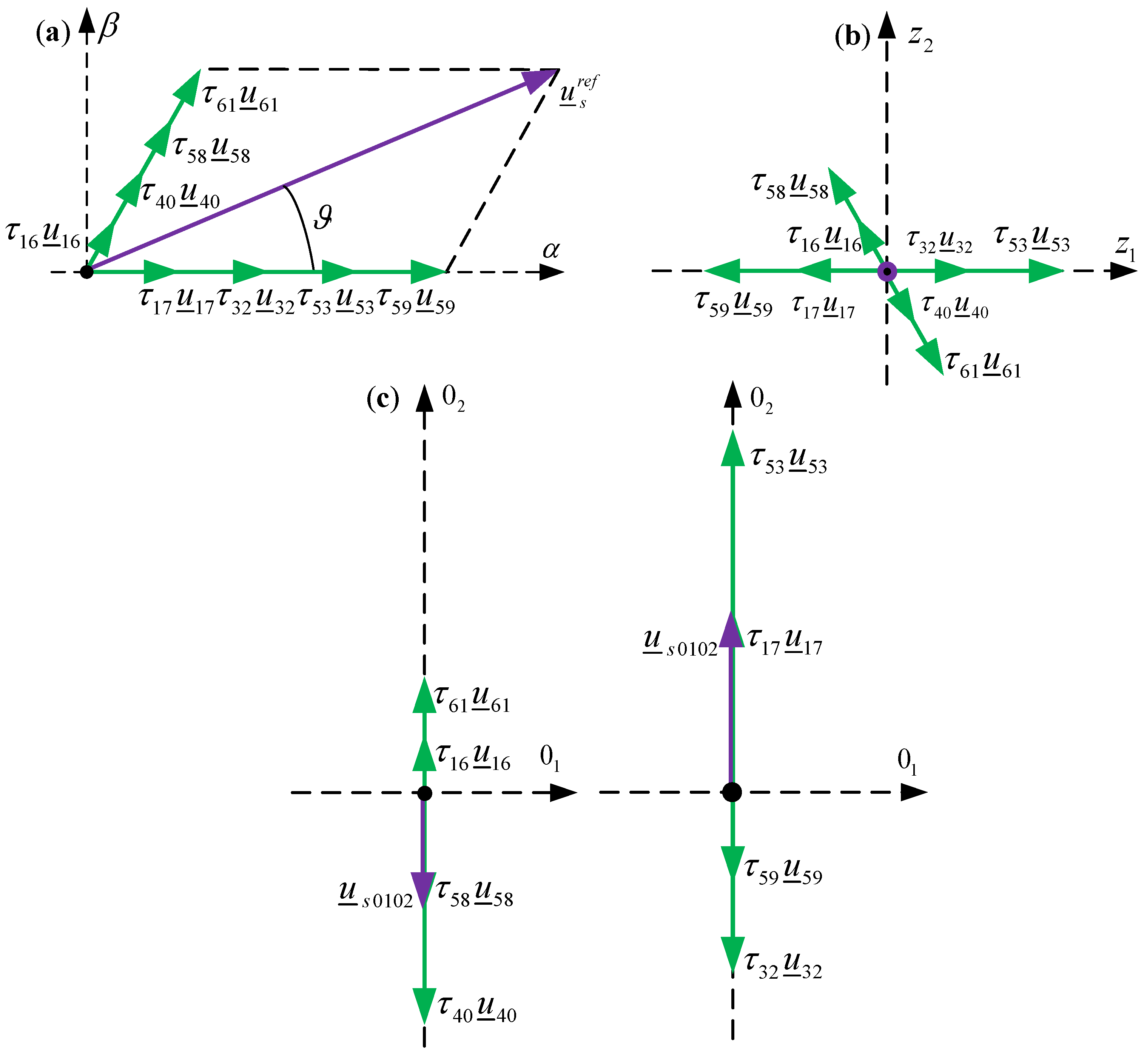
There are a lot of short vectors to be selected for each of the six possible sectors. However, to eliminate the z1z2 components in voltage and current, the vectors should be selected in pairs. This means, for example, that in sector 1, vectors 17 and 32 could be selected to create the α component of the reference vector, while vectors 16 and 40 could create the β component. This approach, however, favors vectors containing zeros in a binary convention, and lower inverter switches would be mainly used. Therefore, in this paper we elected to use not four but eight short vectors, as shown in Figure 9a. In such an algorithm the switches are utilized in a balanced manner.
The eight vectors are used symmetrically, i.e., the normalized time of each vector is the same:
τ 16 = τ 40 = τ 58 = τ 61 = 3 2 u ¯ s r e f u d sin π / 3 ϑ τ 17 = τ 32 = τ 53 = τ 59 = 3 2 u ¯ s r e f u d sin ϑ τ 0 = τ 63 = 1 τ 16 τ 40 τ 58 τ 61 τ 17 τ 32 τ 53 τ 59 / 2
The modulation can be described using the following formula:
u ¯ s r e f = u ¯ 0 τ 0 + u ¯ 17 τ 17 + u ¯ 32 τ 32 + u ¯ 53 τ 53 + u ¯ 59 τ 59 + u ¯ 16 τ 16 + u ¯ 40 τ 40 + u ¯ 58 τ 58 + u ¯ 61 τ 61 + u ¯ 63 τ 63

7. Duty Cycles

To minimize the commutation losses, only one switching on and one switching off transition should take place in each phase during one switching period of the SVM. Moreover, this approach is natural for modern microcontrollers applied in the industry—they require the definition of their duty cycle in the range of 0 to 100%. The following formula can be used to calculate the duty cycle in the case of the classical SVM method with long vectors only and two zero vectors (Section 6.1):
d A d B d C d D d E d F = U 0 1 U 49 ( 1 ) U 56 ( 1 ) U 63 ( 1 ) U 0 2 U 49 ( 2 ) U 56 ( 2 ) U 63 ( 2 ) U 0 3 U 49 ( 3 ) U 56 ( 3 ) U 63 ( 3 ) U 0 4 U 49 ( 4 ) U 56 ( 4 ) U 63 ( 4 ) U 0 5 U 49 ( 5 ) U 56 ( 5 ) U 63 ( 5 ) U 0 6 U 49 ( 6 ) U 56 ( 6 ) U 63 ( 6 ) τ 0 τ 49 τ 56 τ 63
where UY(k) is the binary component of the vector which can be equal to 0 or 1. The duty cycle of the remaining methods can be calculated using the following generalized formula:
d X = k = 1 k Y U Y ( X ) τ Y
Thus, the duty cycle of phase X is equal to the sum of the vector binary components multiplied by their corresponding normalized times.
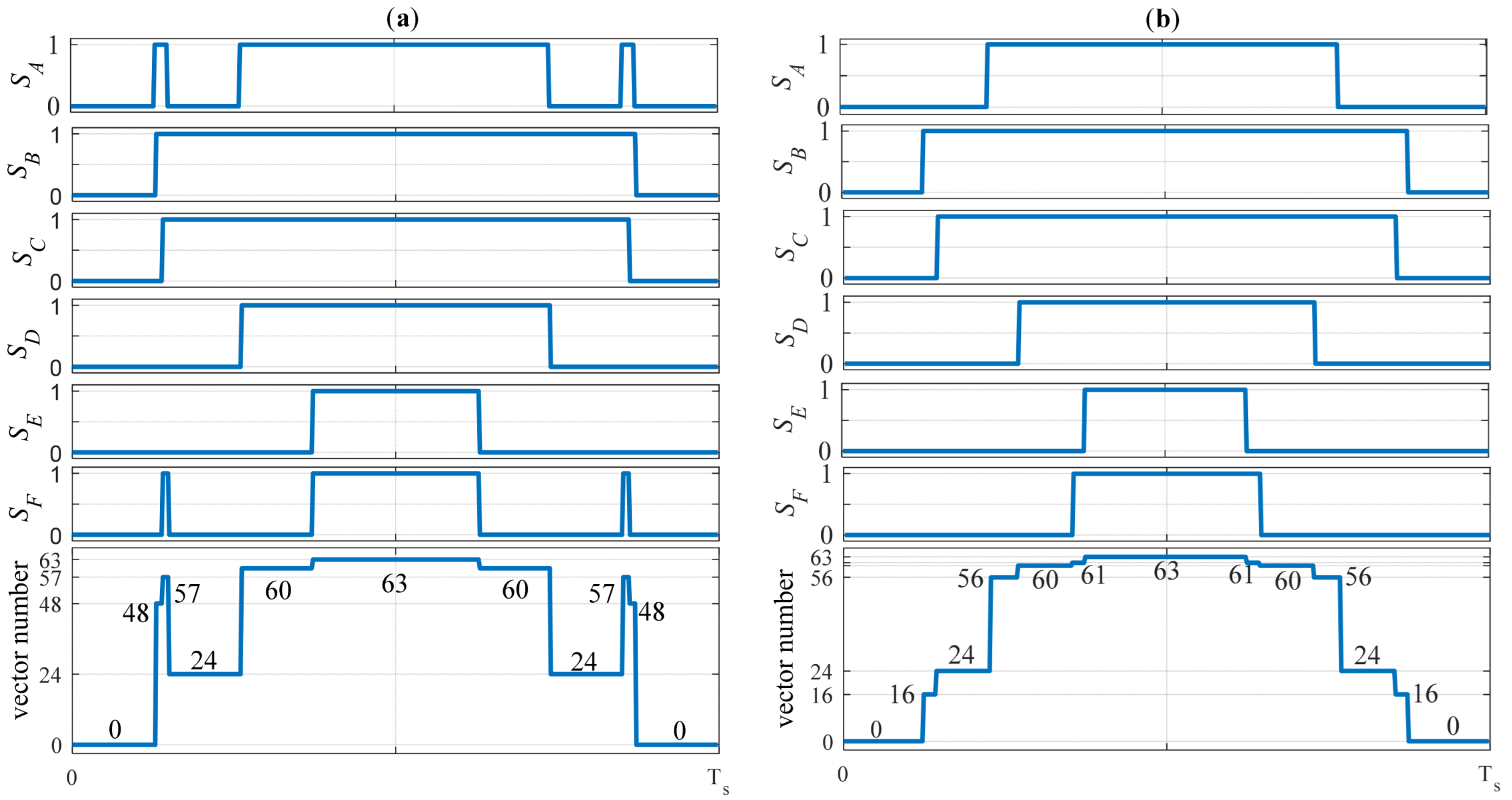
It must be noted here that this approach does not modify the average phase voltage over the switching period. However, it can rearrange and modify the voltage vectors obtained. This is shown in Figure 10, where the SVM with medium vectors only is selected as an example. It can be seen that in the case of the default approach (Figure 10a), only medium vectors are used—48, 24, 57 and 60—alongside two zero vectors, 0 and 63. If the duty cycles are recalculated (21), two medium vectors remain unchanged—24 and 60—but two others appear: 16 and 61. Additionally, long vector 56 appears (Figure 10b). Thus, if long vectors appear, the modulation characteristics must be different in the overmodulation region between the two approaches.
The approach shown in Figure 10b, as it is a microcontroller-based solution, will be used further in this paper.

8. Experimental Test Results

8.1. Duty Cycles in Experimental Tests

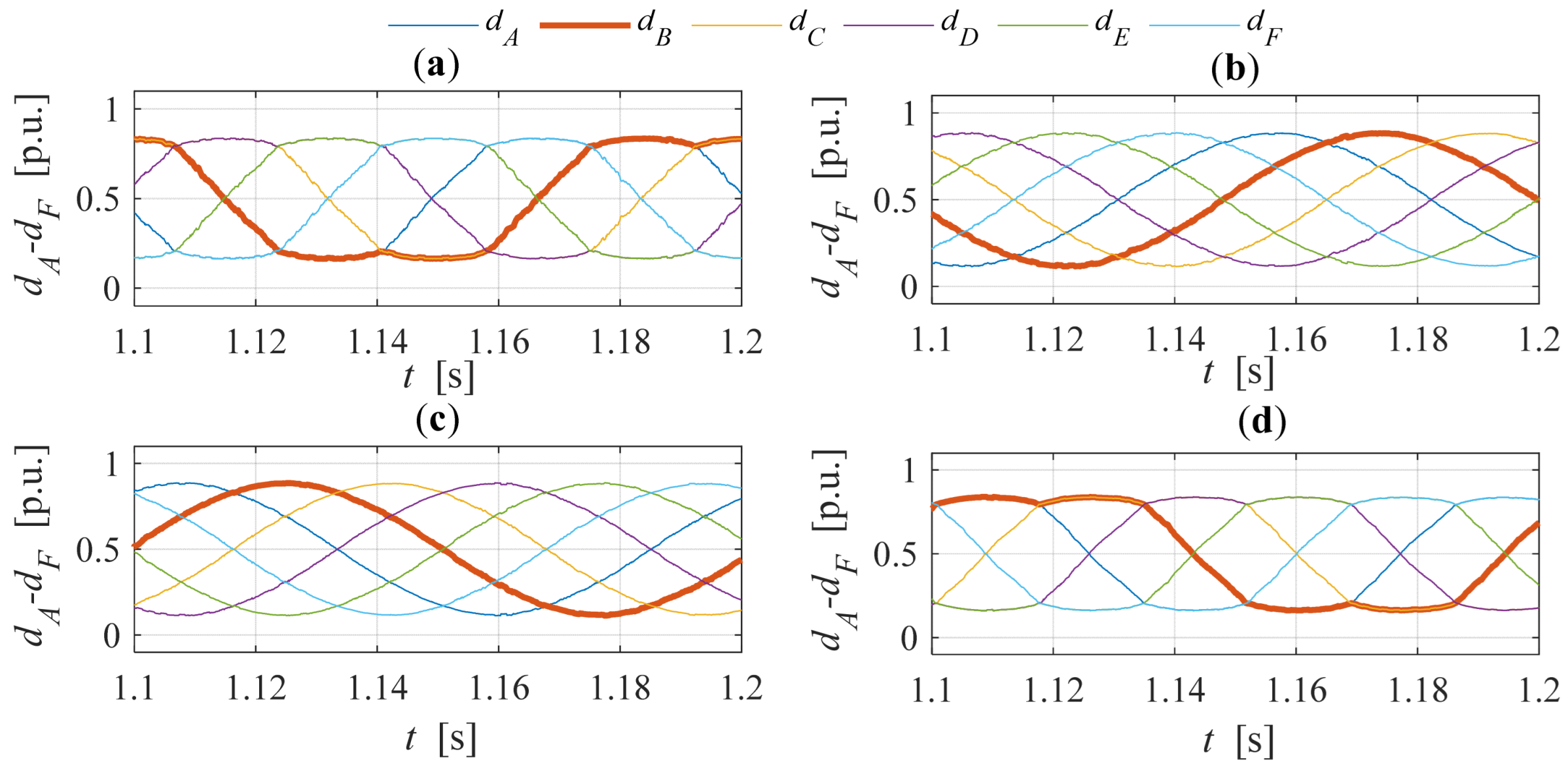
The comparison between the duty cycles obtained for all four analyzed methods is shown in Figure 11. It can be seen that in the cases of the traditional SVM method adapted from three-phase systems (Figure 11a) and the SVM method with short vectors only (Figure 11d), a similar characteristic shape is visible. This reduces the amplitude of the duty cycle compared to a sinusoidal signal but also adds a third harmonic into the voltage and motor currents inherently, as will be shown in the following section. However, in the case of the proposed SVM (Figure 11b) and the SVM with medium vectors only (Figure 11d), the duty cycles are circular, similar to sinusoidal modulation.
Table 2 and Figure 12 summarize the operation of the proposed modulation method for different modulation indices. It can be seen that if the index is smaller than 3 / 2 , the shape of the duty cycle is sinusoidal (Figure 12a) and the sum of τ21 and τ42 is always lower than τzero. This indicates that the 01–02 frame components are fully compensated.
If the modulation index is between 3 / 2 and 1, full compensation is not possible and the required time for vectors 21 and 42 is sometimes longer than the available time for all zero vectors. The shape of the duty cycles is no longer sinusoidal (Figure 12b). However, the proposed SVM method tends to limit the duty cycle between 0% and 100%. This preserves the linear dependence between the reference and the obtained voltage. If the modulation index is between 1 and 2 3 / 3 , the compensation is always partial, but τzero is never zero (Figure 12c). Between 2 3 / 3 and 4/3, the time for the zero vectors sometimes becomes zero (Figure 12e), and above 4/3 it is always zero (Figure 12f), so the compensation of the 01–02 components is not possible at all.

8.2. Effect of Modulation Type on Stator Currents of Induction Motor Operating Under DFOC

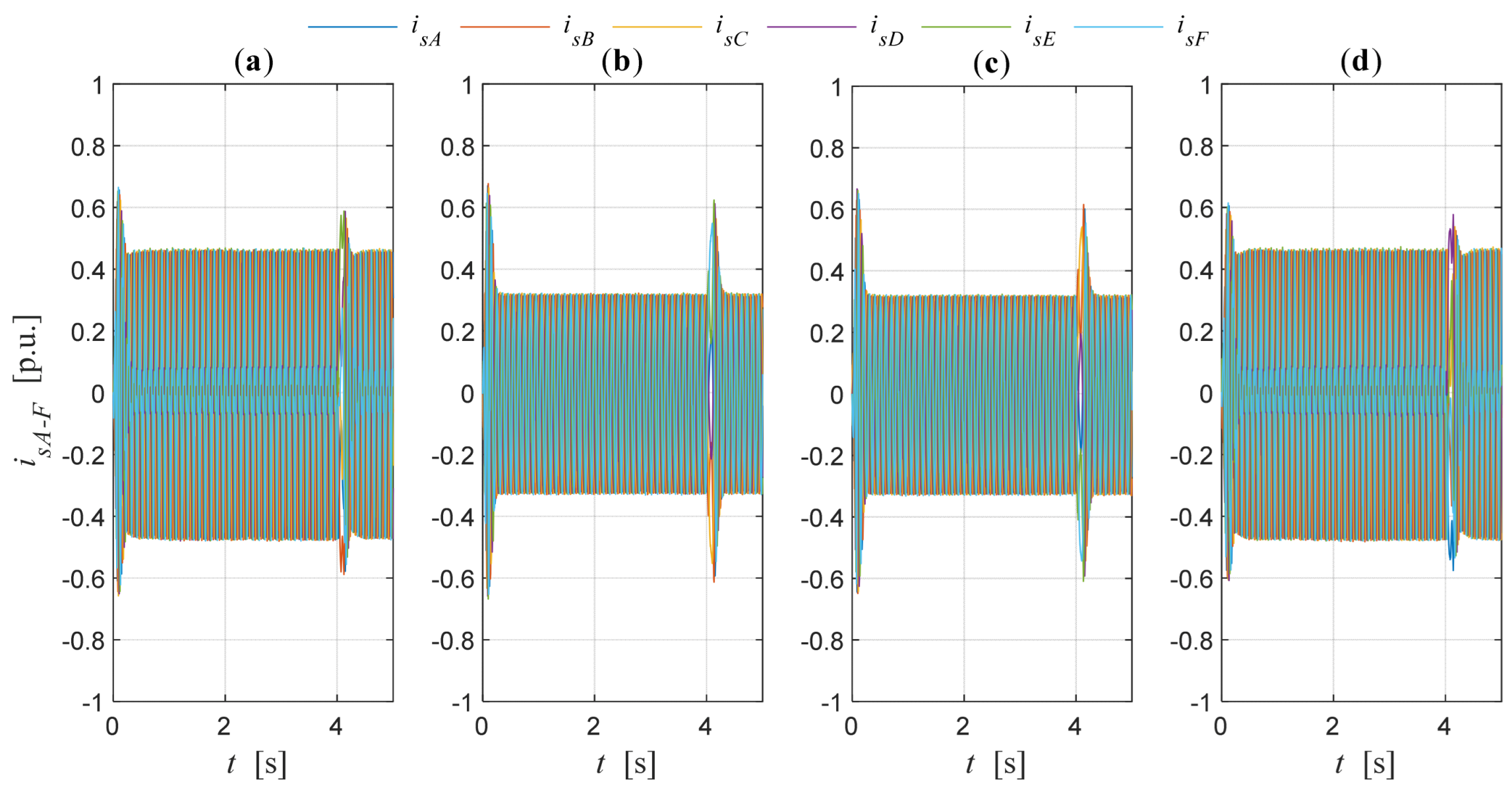
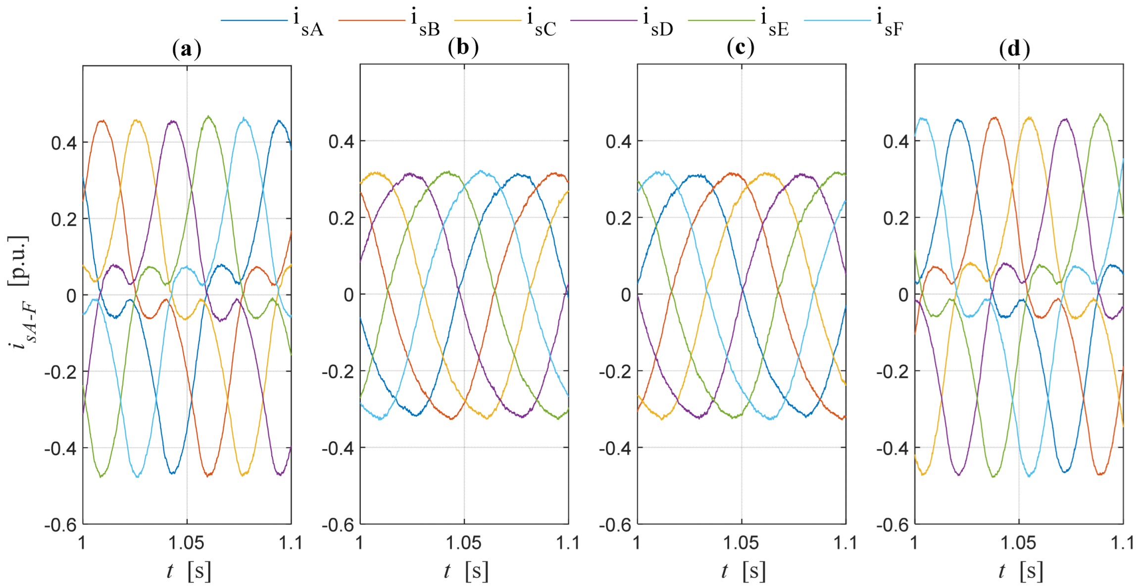
The phase currents of a six-phase induction motor operating under DFOC are shown in Figure 13. The waveforms were obtained in the same conditions shown in Figure 5. It can be seen that the amplitude of the currents is significantly increased when classical SVM with long vectors (Figure 13a) or SVM with short vectors (Figure 13d) only are used, compared to the remaining two methods presented (Figure 13b,c). These increases in amplitude are connected with an additional third harmonic component, especially visible in Figure 14. The figure presents a zoom in on the phase currents—the very poor quality of the currents when no compensation is applied should be easily noted.
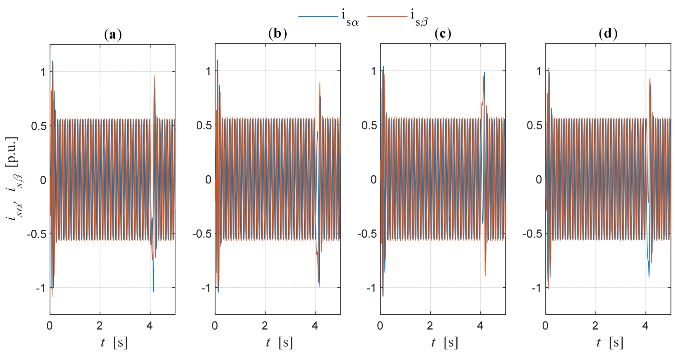
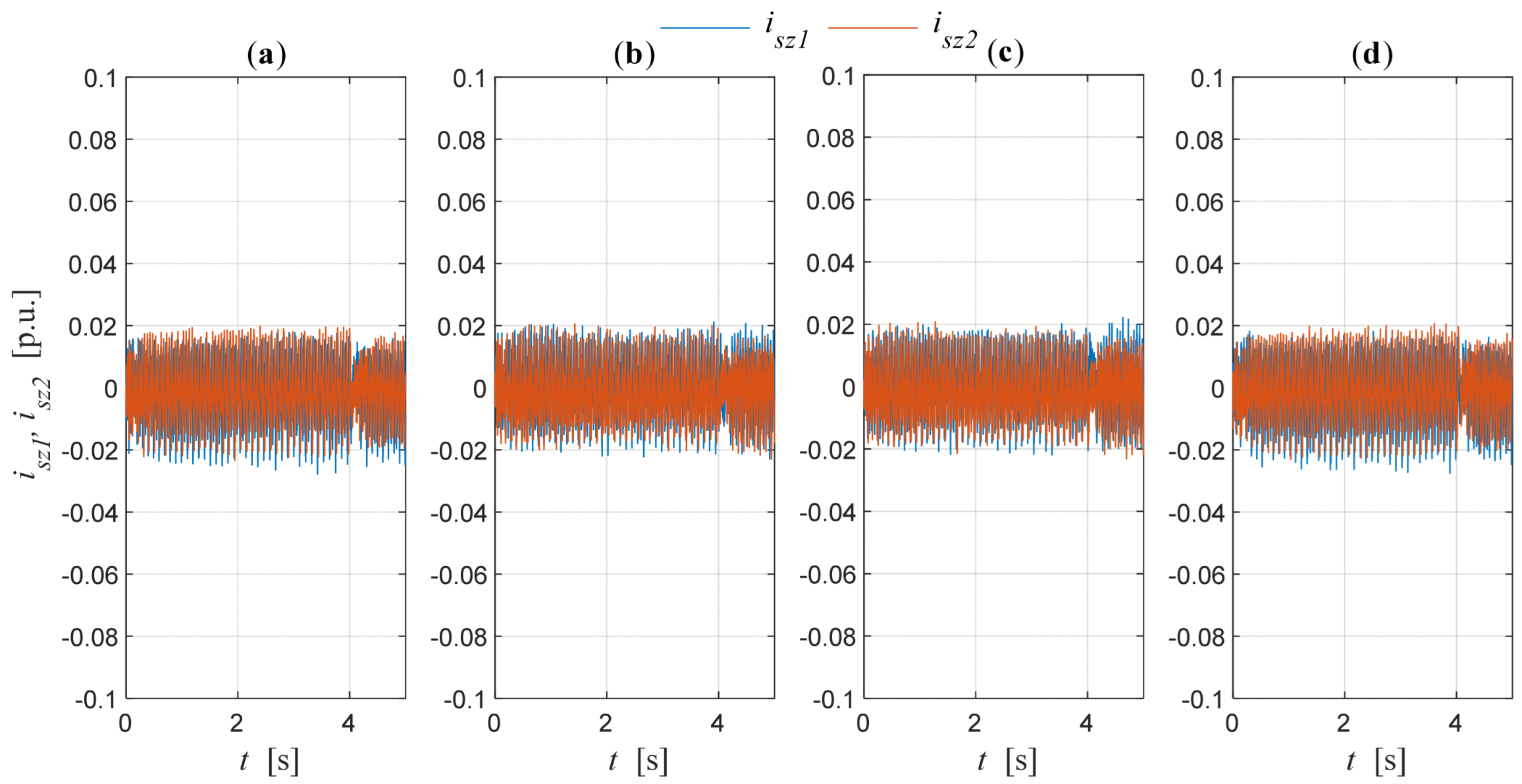
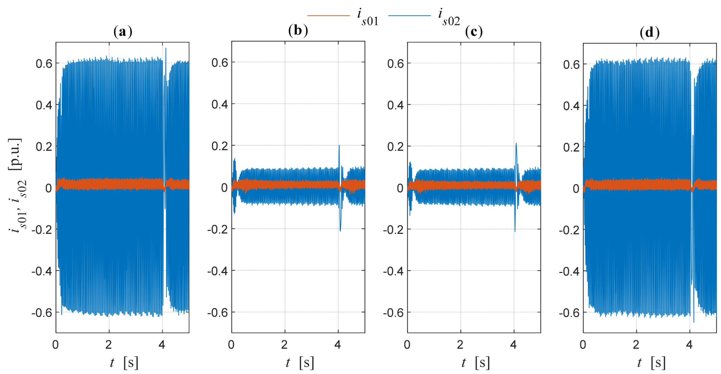
Figure 15 presents the currents in the stationary αβ reference frame. All the waveforms are almost identical as they are defined by the control structure in the same conditions of motor speed and load torque. Figure 16 proves that all the presented methods compensate for the z1z2 components of the motor current in the analyzed motor operating conditions. Finally, Figure 17 shows that the 01–02 components are not compensated in the cases of the traditional SVM method and the SVM method with short vectors only. However, they are significantly smaller if the SVM method with medium vectors only or the proposed modulation method are considered.

9. Modulation Characteristics

Figure 18 shows the odd harmonics of the phase voltage of the inverter, starting from the fundamental component (Figure 18a) up to the ninth component (Figure 18e). All components are normalized to the maximum value of the first harmonic. The characteristics are shown for four different analyzed SVM methods with short, medium, long and modified long vectors, each one in two different versions: the default one and the one based on duty cycle recalculation. The results were prepared with the MATLAB-Simulink models with the Euler solver (ode1) and a fixed-step size equal to 1 × 10⁻⁷ s. The switching frequency was set to 5 kHz, while the fundamental frequency of the reference voltage was equal to 60 Hz.
Figure 18a shows that in a linear range (region I and region II), e.g., when the modulation index is lower than one, the first harmonic of the voltage increases in a linear way. This means that the reference voltage is the same as the output voltage. In this range, all the characteristics, except the one for default short vectors, are identical. If the classical SVM or the proposed SVM with long vectors and modified zero vectors are applied, the linear range is extended up to the end of region III. However, in the case of the SMV with medium vectors only, the characteristics become strongly nonlinear and enter the range of overmodulation (region III and higher). Remarkably, the default SVM with medium vectors only is saturated and never reaches the maximum possible VSI voltage. Its duty cycle version is not limited, though. This occurs because the long vectors are produced then, as well. It is clear that the linear range of the default SVM with short vectors only is limited to 50% of the linear range of the SVM with long vectors. However, the duty-cycle-based version of the SVM with short vectors is similar to other SVM methods regarding the fundamental component of the voltage.
Figure 18b presents the third harmonic component, which is visible here only because the motor is connected in the single-star topology. Otherwise, it would be zero. The classical SVM method with long vectors as well as SVM with short vectors both produce the largest third harmonic contents, starting as early as in region I and up to region V. When the proposed modification of the SVM is applied, this harmonic component is eliminated up to the beginning of region II. Then, it increases and reaches a similar level as in traditional SVM methods around the transition between region III and region IV. The limited voltage value of the default SVM with medium voltage is rewarded with a completely zero value of the third harmonic component (green line in Figure 18b). Recalculating the duty cycles in the case of this method introduces this harmonic component starting from region III, i.e., when the modulation index is larger than 1.
The default SVM with medium vectors only, that is characterized with the lowest third harmonic component, introduces a large fifth harmonic component starting from when the modulation index is equal to one (Figure 18c). In this case recalculating the duty cycle helps to reduce the fifth harmonic. There are no differences between the classical and the proposed SVM methods when this component is considered. Moreover, SVM with short vectors in both versions, especially in the default version, produces the largest fifth harmonic component of all the analyzed methods.
The SVM method with short vectors only produces the largest seventh harmonic component. There are no differences between the SVM methods with long vectors when the seventh harmonic component is considered (Figure 18d). However, the default versions produce much larger contents of this component in the output voltage than the duty-cycle-based versions. Similarly to the third harmonic, the classical SVM method with long vectors produces the highest content of the ninth harmonic, starting from region I, while default SVM with medium vectors only produces no harmonic content, as shown in Figure 18e.

10. Conclusions

This paper presents a comprehensive comparison of Space Vector Modulation methods applied to control a six-phase Voltage Source Inverter supplying a six-phase induction motor. Four different possibilities are considered: SVM with short vectors only, SVM with medium vectors, classical SVM with long vectors only and the one proposed in this study—an SVM method with long vectors only and a modified distribution of zero vectors. Additionally, the differences between the default approach and duty-cycle-based modulation are presented. The influence of the analyzed methods on Direct Field-Oriented Control is presented in terms of the motor phase currents and all six components in stationary reference frames. Simulation and experimental test results are included as well. A detailed low-order higher harmonics analysis is shown and compared for each of the SVM methods. The paper describes the difference between the single- and double-star topologies of motor windings, but focuses on the former, as it is more reliable, more difficult in terms of modulation and produces higher harmonics.
It is proved that the classical SVM method with long vectors only, adapted from three-phase systems, cannot be applied in six-phase systems with single neutral point, as it produces third harmonic components in both voltage and current over the entire range of voltage variation. The same is true for SVM with short vectors only. Additionally, the voltage that can be achieved in the case of the second method is constrained. The only method that does not generate any third (and its multiple) harmonic components is the default version of the SVM method with medium vectors. However, its amplitude is inherently limited in the overmodulation region. On the other hand, it produces the largest fifth harmonic among all the analyzed methods. A reasonable solution is the proposed modulation method—SVM with long vectors and a modified distribution of zero voltage vectors, applied to compensate the components responsible for third harmonic generation. This method is characterized by a longer linear operating range compared to the modulation with medium vectors only, no third harmonic being produced in the linear range and relatively low harmonic content.

Author Contributions

Conceptualization, J.L. and G.T.; methodology, J.L. and G.T.; software, J.L. and G.T.; validation, J.L. and G.T.; formal analysis, J.L. and G.T.; investigation, J.L. and G.T.; data curation, J.L.; writing—original draft preparation, J.L. and G.T.; writing—review and editing, G.T.; visualization, J.L. All authors have read and agreed to the published version of the manuscript.

Funding

This research received no external funding.

Data Availability Statement

The data presented in this study are available on request from the first author.

Conflicts of Interest

The authors declare no conflicts of interest.

Appendix A

The parameters and nominal data of the tested six-phase squirrel-cage induction motor are as follows: PN = 1.5 kW; UfN = 230 V; IfN = 2 A; fN = 50 Hz; pp = 2; Rs = 7.8 Ω; Rr = 11 Ω; Lls = Llr = 0.06 H; Lm = 0.75 H.

References

  1. Emadi, A.; Lee, Y.J.; Rajashekara, K. Power Electronics and Motor Drives in Electric, Hybrid Electric and Plug-In Hybrid Electric Vehicles. IEEE Trans. Ind. Electron. 2008, 55, 2237–2245. [Google Scholar] [CrossRef]
  2. Faiz, J.; Sharifan, M.B.B.; Keyhani, A.; Proca, A.B. Sensorless Direct Torque Control of Induction Motors Used in Electric Vehicle. IEEE Trans. Energy Convers. 2003, 18, 1–10. [Google Scholar] [CrossRef]
  3. Hajary, A.; Kianinezhad, R.; Seifossadat, S.G.; Mortazavi, S.S.; Saffarian, A. Detection and Localization of Open-Phase Fault in Three-Phase Induction Motor Drives Using Second Order Rotational Park Transformation. IEEE Trans. Power Electron. 2019, 34, 11241–11252. [Google Scholar] [CrossRef]
  4. Wolkiewicz, M.; Tarchała, G.; Orłowska-Kowalska, T.; Kowalski Cz, T. Online Stator Interturn Short Circuits Monitoring in the DFOC Induction-Motor Drive. IEEE Trans. Ind. Electron. 2016, 63, 2517–2528. [Google Scholar] [CrossRef]
  5. Bojoi, R.; Cavagnino, A.; Tenconi, A.; Tessarolo, A.; Vaschetto, S. Multiphase Electrical Machines and Drives in the Transportation Electrification. In Proceedings of the IEEE 1st International Forum on Research and Technologies for Society and Industry Leveraging a Better Tomorrow (RTSI), Turin, Italy, 16–18 September 2015. [Google Scholar]
  6. Frikha, M.A.; Croonen, J.; Deepak, K.; Benomar, Y.; El Baghdadi, M.; Hegazy, O. Multiphase Motors and Drive Systems for Electric Vehicle Powertrains: State of the Art Analysis and Future Trends. Energies 2023, 16, 768. [Google Scholar] [CrossRef]
  7. Levi, E. Multiphase Electric Machines for Variable-Speed Applications. IEEE Trans. Ind. Electron. 2008, 55, 1893–1909. [Google Scholar] [CrossRef]
  8. Levi, E.; Bojoi, R.; Profumo, F.; Toliyat, H.A.; Williamson, S. Multiphase Induction Motor Drives—A Technology Status Review. IET Electr. Power Appl. 2007, 1, 489–516. [Google Scholar] [CrossRef]
  9. Listwan, J.; Oleszczyszyn, P. Analysis of the Drive of the Electric Vehicle with Six-Phase Induction Motor. Power Electron. Drives 2023, 8, 252–274. [Google Scholar] [CrossRef]
  10. Nuca, I.; Cazac, V.; Turcanu, A.; Burduniuc, M. Development of Traction System with Six Phase Induction Motor for Urban Passenger Vehicle. In Proceedings of the 11th International Conference and Exposition on Electrical and Power Engineering (EPE 2020), Iasi, Romania, 22–23 October 2020. [Google Scholar]
  11. Salem, A.; Narimani, M. A Review on Multiphase Drives for Automotive Traction Applications. IEEE Trans. Transp. Electrif. 2019, 5, 1329–1348. [Google Scholar] [CrossRef]
  12. Iqbal, A.; Singh, G.K. PSO Based Controlled Six-phase Grid Connected Induction Generator for Wind Energy Generation. CES Trans. Electr. Mach. Syst. 2021, 5, 41–49. [Google Scholar] [CrossRef]
  13. Pantea, A.; Yazidi, A.; Betin, F.; Carriere, S.; Sivert, A.; Vacossin, B.; Henao, H.; Capolino, G.-A. Fault-Tolerant Control of a Low-Speed Six-Phase Induction Generator for Wind Turbines. IEEE Trans. Ind. Appl. 2019, 55, 426–436. [Google Scholar] [CrossRef]
  14. Bodo, N.; Levi, E.; Subotic, I.; Espina, J.; Empringham, L.; Johnson, C.M. Efficiency Evaluation of Fully Integrated On-Board EV Battery Chargers with Nine-Phase Machines. IEEE Trans. Energy Convers. 2017, 32, 257–266. [Google Scholar] [CrossRef]
  15. Diab, M.S.; Elserougi, A.A.; Abdel-Khalik, A.S.; Massoud, A.M.; Ahmed, S. A Nine-Switch-Converter-Based Integrated Motor Drive and Battery Charger System for EVs Using Symmetrical Six-Phase Machines. IEEE Trans. Ind. Electron. 2016, 63, 5326–5335. [Google Scholar] [CrossRef]
  16. Dujic, D.; Grandi, G.; Jones, M.; Levi, E. A Space Vector PWM Scheme for Multifrequency Output Voltage Generation with Multiphase Voltage-Source Inverters. IEEE Trans. Ind. Electron. 2008, 55, 1943–1955. [Google Scholar] [CrossRef]
  17. Iqbal, A.; Levi, E.; Jones, M.; Vukosavic, S.N. Generalised Sinusoidal PWM with Harmonic Injection for Multi-Phase VSIs. In Proceedings of the 37th IEEE Power Electronics Specialists Conference, Jeju, Republic of Korea, 18–22 June 2006. [Google Scholar]
  18. Kianinezhad, R.; Nahid, B.; Betin, F.; Capolino, G.A. Multi-Vector SVM: A New Approach to Space Vector Modulation Control for Six-Phase Induction Machines. In Proceedings of the 31st Annual Conference of IEEE Industrial Society, IECON, Raleigh, NC, USA, 6–10 November 2005; pp. 1359–1364. [Google Scholar]
  19. Zandzadeh, M.J.; Saniei, M.; Kianinezhad, R. Space vector modulation with reduced common mode voltage for six-phase drives. COMPEL—Int. J. Comput. Math. Electr. Electron. Eng. 2020, 39, 395–411. [Google Scholar] [CrossRef]
  20. Listwan, J.; Pienkowski, K. Comparative Analysis of Control Methods with Model Reference Adaptive System Estimators of a Seven-Phase Induction Motor with Encoder Failure. Energies 2021, 14, 1147. [Google Scholar] [CrossRef]
  21. Liu, Z.; Peng, L.; Yongdong, L.; Zheng, Z.; Wang, K. Modeling and Control of 15-Phase Induction Machine under One Phase Open Circuit Fault. In Proceedings of the International Conference on Electrical Machines and Systems, Busan, Republic of Korea, 26–29 October 2013. [Google Scholar]
  22. Bojoi, R.; Lazzari, M.; Profumo, F.; Tenconi, A. Digital Field-Oriented Control for Dual Three-Phase Induction Motor Drives. IEEE Trans. Ind. Appl. 2003, 39, 752–760. [Google Scholar] [CrossRef]
  23. Che, H.S.; Duran, M.J.; Levi, E.; Jones, M.; Hew, W.P.; Rahim, N.A. Postfault Operation of an Asymmetrical Six-Phase Induction Machine With Single and Two Isolated Neutral Points. IEEE Trans. Power Electron. 2014, 29, 5406–5416. [Google Scholar] [CrossRef]
  24. Zhang, M.; Yuan, M.; Jiang, J. A Comprehensive Review of the Multiphase Motor Drive Topologies for High-Power Electric Vehicle: Current Status, Research Challenges and Future Trends. IEEE Trans. Transp. Electrif. 2025, 11, 3631–3654. [Google Scholar] [CrossRef]
  25. Soares, E.L.; Jacobina, C.B.; de Freitas, N.B.; Rocha, N.; Maia, C.N.; Lima, M.N. A Multilevel Open-End Winding Six-Phase Induction Motor Drive Topology Based on Three Two-Level Three-Phase Inverters. IEEE Trans. Ind. Appl. 2023, 59, 6360–6372. [Google Scholar] [CrossRef]
  26. Moghadasian, M.; Kianinezhad, R.; Betin, F.; Capolino, G.A. Torque Ripple Minimization in Direct Torque Control of Six-Phase Induction Machines Using Fuzzy Inference Systems. In Proceedings of the XIX International Conference on Electrical Machines (ICEM), Rome, Italy, 6–8 September 2010. [Google Scholar]
  27. Lipinskis, T.; Baskys, A.; Rutkauskas, A. Six-Phase Voltage Forming Method Using the Largest Magnitude Space Vectors. Electron. Elektrotechnika 2013, 19, 99–102. [Google Scholar] [CrossRef]
  28. Listwan, J. Analysis of Fauls States in Drive Systems with Multi-Phase Induction Motors. Arch. Electr. Eng. 2019, 68, 817–830. [Google Scholar]
Figure 1. Block diagrams of the power supply system of 6-phase induction motors (a) with one neutral point and (b) with a double neutral point.
Energies 18 03122 g001
Figure 2. The stator voltage vectors generated by a six-phase VSI in (a) the αβ coordinate system, (b) the z1z2 coordinate system, (c) the 01–02 coordinate system (only in the case of a single-star topology).
Energies 18 03122 g002
Figure 3. Block diagram of experimental setup.
Energies 18 03122 g003
Figure 4. DFOC system of 6-phase induction motor.
Energies 18 03122 g004
Figure 5. Experimental study of DFOC of 6-phase induction motor: (a) reference and measured speeds; (b) reference and estimated magnitudes of rotor flux vector; (c) 6-phase stator currents; (d) reference and measured x-axis current components; (e) reference and measured y-axis current components.
Energies 18 03122 g005
Figure 6. The reference voltage vector synthesis in sector 1 in the case of the traditional Space Vector Modulation algorithm of a 6-phase voltage inverter using long and zero voltage vectors (a) in the αβ coordinate system and (b) in the 01–02 coordinate system; single-star topology.
Energies 18 03122 g006
Figure 7. Reference voltage synthesis in sector 1 for SVM when using only medium and zero voltage vectors (a) in αβ frame and (b) in z1z2 frame.
Energies 18 03122 g007
Figure 8. Selected voltage vectors used to implement the vector modulation algorithm of a 6-phase voltage inverter using long and four zero voltage vectors in the 01–02 coordinate system.
Energies 18 03122 g008
Figure 9. Selected voltage vectors used to implement the vector modulation algorithm of a 6-phase voltage inverter using short and zero voltage vectors (a) in the αβ coordinate system, (b) in the z1z2 coordinate system, (c) in the 01–02 coordinate system.
Energies 18 03122 g009
Figure 10. Comparison of (a) default voltage vectors during one switching period, (b) voltage vectors when duty cycle is calculated.
Energies 18 03122 g010
Figure 11. Duty cycles for 6-phase induction motor under DFOC: (a) classical SVM with only 6 long vectors; (b) proposed SVM with 6 long vectors and modified zero vector distribution; (c) SVM with only 6 medium vectors; (d) SVM with only short vectors. Experimental results.
Energies 18 03122 g011
Figure 12. Duty cycles of proposed SVM method with modified zero vector distribution for different modulation indices: (a) 0.433 (center of region I), (b) 0.933 (center of region II), (c) 1.0 (d) 1.0774 (center of region III), (e) 1.244 (center of region IV), (f) 1.4 (region V).
Energies 18 03122 g012
Figure 13. The 6-phase currents in cases of different modulation methods: (a) classical SVM with only 6 long vectors, (b) proposed SVM with 6 long vectors and modified zero vector distribution, (c) only medium vectors, (d) only short vectors; experimental results.
Energies 18 03122 g013
Figure 14. The 6-phase currents (zoom) in cases of different modulation methods: (a) classical SVM with only 6 long vectors, (b) proposed SVM with 6 long vectors and modified zero vector distribution, (c) SVM with only medium vectors, (d) SVM with only short vectors; experimental results.
Energies 18 03122 g014
Figure 15. αβ current components in cases of different modulation methods: (a) classical SVM with only 6 long vectors, (b) proposed SVM with 6 long vectors and modified zero vector distribution, (c) SVM with only medium vectors, (d) SVM with only short vectors; experimental results.
Energies 18 03122 g015
Figure 16. z1z2 current components in cases of different modulation methods: (a) classical SVM with only 6 long vectors, (b) proposed SVM with 6 long vectors and modified zero vector distribution, (c) SVM with only medium vectors, (d) SVM with only short vectors; experimental results.
Energies 18 03122 g016
Figure 17. 01–02 current components in cases of different modulation methods: (a) classical SVM with only 6 long vectors, (b) proposed SVM with 6 long vectors and modified zero vector distribution, (c) SVM with only medium vectors, (d) SVM with only short vectors; experimental results.
Energies 18 03122 g017
Figure 18. Fundamental harmonic (a) and higher harmonics—3rd (b), 5th (c), 7th (d) and 9th (e)—of all analyzed SVM methods for single-star connection; simulation study.
Energies 18 03122 g018
Table 1. Amplitudes of voltage vectors in different coordinate frames.
Long
Vectors
Medium
Vectors
Short
Vectors
Zero
Vectors
α β 2 3 3 u d u d 3 3 u d 0
z 1 z 2 0 3 3 u d 3 3 u d ,   u d 0 ,   2 3 3 u d
0 1 0 2 single star 3 3 2 u d 0 3 3 2 u d , 2 3 3 2 u d 0 ,   3 2 u d
double star0000
Table 2. 01–02 component compensation level in function of modulation index for proposed modulation method.
RegionModulation Index01–02 Component CompensationTotal Time for Zero Vectors τ 21   +   τ 42   >   τ z e r o
fromto
I0 3 / 2 always full compensationnever zeronever
II 3 / 2 1sometimes full compensation/sometimes partial compensationnever zerosometimes
III1 2 3 / 3 always partial compensationnever zeroalways
IV 2 3 / 3 4 / 3 sometimes partial compensation/sometimes no compensationsometimes zeroalways
V 4 / 3 no compensationalways zeroalways
Disclaimer/Publisher’s Note: The statements, opinions and data contained in all publications are solely those of the individual author(s) and contributor(s) and not of MDPI and/or the editor(s). MDPI and/or the editor(s) disclaim responsibility for any injury to people or property resulting from any ideas, methods, instructions or products referred to in the content.