
Advances in HVDC Systems: Aspects, Principles, and a Comprehensive Review of Signal Processing Techniques for Fault Detection


Abstract
1. Introduction
1.1. Evolution of HVDC Systems
1.2. Advantages of HVDC over HVAC Technology

| Aspects | HVDC Transmission | HVAC Transmission |
|---|---|---|
| Renewable energy integration [12,13] | Easy renewable energy integration | Difficult renewable energy integration |
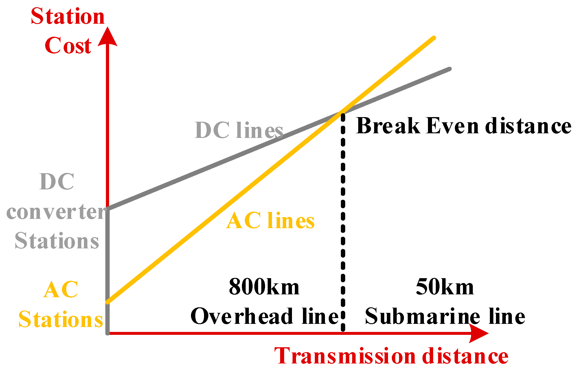
| Power transmission distance [13,14] | HVDC technology prefers if the transfer distance is larger than the breakeven distance (generally, 800 km overhead line or 50 km submarine line) (Figure 2) | HVAC technology dominates if the transfer distance is smaller than breakeven distance |
| Power losses [15,16,17] | Less power losses due to no reactive power losses and no skin effects | Higher power losses due to reactive power losses and skin effects |
| Reactive power compensation [18,19] | No reactive power compensation required | Reactive power compensation is essential |
| Grid stability [15,16] | Allows AC system connections with two different frequencies | Difficult to achieve system connection with two different frequencies |
| Voltage regulation [13,17] | Easy voltage regulation due to only resistive losses | Complexed voltage regulation is needed due to reactive losses |
| Economical for long distance-transmission [20,21] |
|
|
1.3. HVDC Applications in Power Networks and Developments in Asis-Pacific Region
1.3.1. HVDC Systems in China
1.3.2. HVDC Systems in India
1.3.3. HVDC Systems in Japan
1.3.4. HVDC Systems in Australia
1.3.5. HVDC Systems in New Zealand
1.4. Current Challenges and Research Scopes
- ○
- A lack of sufficient review of signal processing methods for VSC-HVDC or multi-terminal HVDC grid fault detection.
- ○
- The insufficiency of a single signal processing method that would comprehensively realize fault detection; for example, wavelet-based techniques can detect a fault but cannot detect the fault location.
- ○
- Limited real-time viability; for example, wavelet packet transformation is sometimes too slow for real-time protection, which is only applied in offline simulations or laboratory validation. Delayed detection in such faults may cause fault propagation and further cascaded failure.
- ○
- Limited use in testing and HIL framework validation under realistic and diverse grid operating conditions.
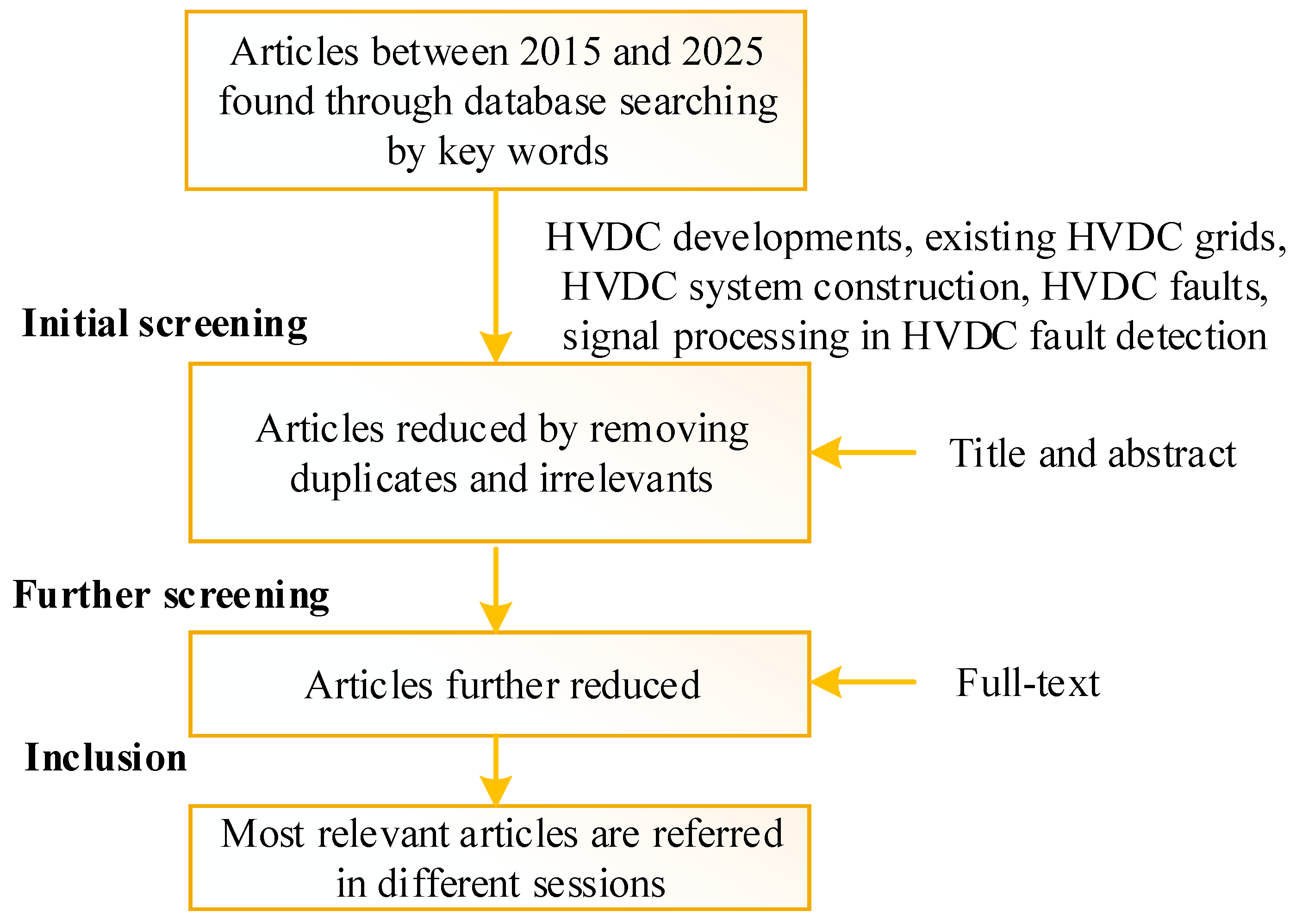
1.5. Reference Selection Methodology
1.6. Paper Organization
2. Basics of HVDC Grids
2.1. Converter-Based HVDC Systems
| Feature | LCC-HVDC | VSC-HVDC | MMC-HVDC |
|---|---|---|---|
| Switching device | Thyristors | IGBTs | IGBT/SiC MOSFET submodules |
| Commutation | Line commutation, grid dependence on natural commutation | Self-commutation (PWM-operation commutation), no grid dependency | Self-commutation (PWM-operation commutation), no grid dependency |
| Harmonics | High harmonics and AC filters needed | No AC filter required | Very low (near-sinusoidal output), good AC waveform quality |
| Dynamic response | Slow dynamic response | Faster dynamic response compared to LCC and more control flexibility to provide AC grid support | Faster dynamic response compared to LCC system and more control flexibility to provide AC grid support |
| Commutation failure (AC fault response) | Vulnerability to commutation failure | No commutation failure | No commutation failure |
| Reactive power | Large amount of reactive power consumption, requires external control (SVC or STATCOM) | Independent control of P and Q, able to provide reactive power compensation | Independent control of P and Q, able to provide reactive power compensation |
| Power rating | Bulk power transmission capability and large power rating | Low power rating | Modular design and high flexibility for scalable voltage levels |
| Power loss | Low power loss | High switching frequency leading to high switching losses | High switching frequency leading to high switching losses |
| Efficiency | High efficiency | Low efficiency | High efficiency |
| Black start Capability | Challenging (due to commutation issues) | Yes | Yes |
| Weak grid Connection (Renewable integration) | Challenging to connect to weak AC systems (requires strong wind, short-circuit ratio SCR > 2) | Compatible with weak AC systems (works with system even short-circuit ratio SCR < 1.5) | Best for weak AC systems (works with system even short-circuit ratio SCR < 1), e.g., offshore wind farms |
| Long distance transmission | Best | Less efficient | Competitive with scalable voltage |
2.2. Pole Configurations in HVDC System
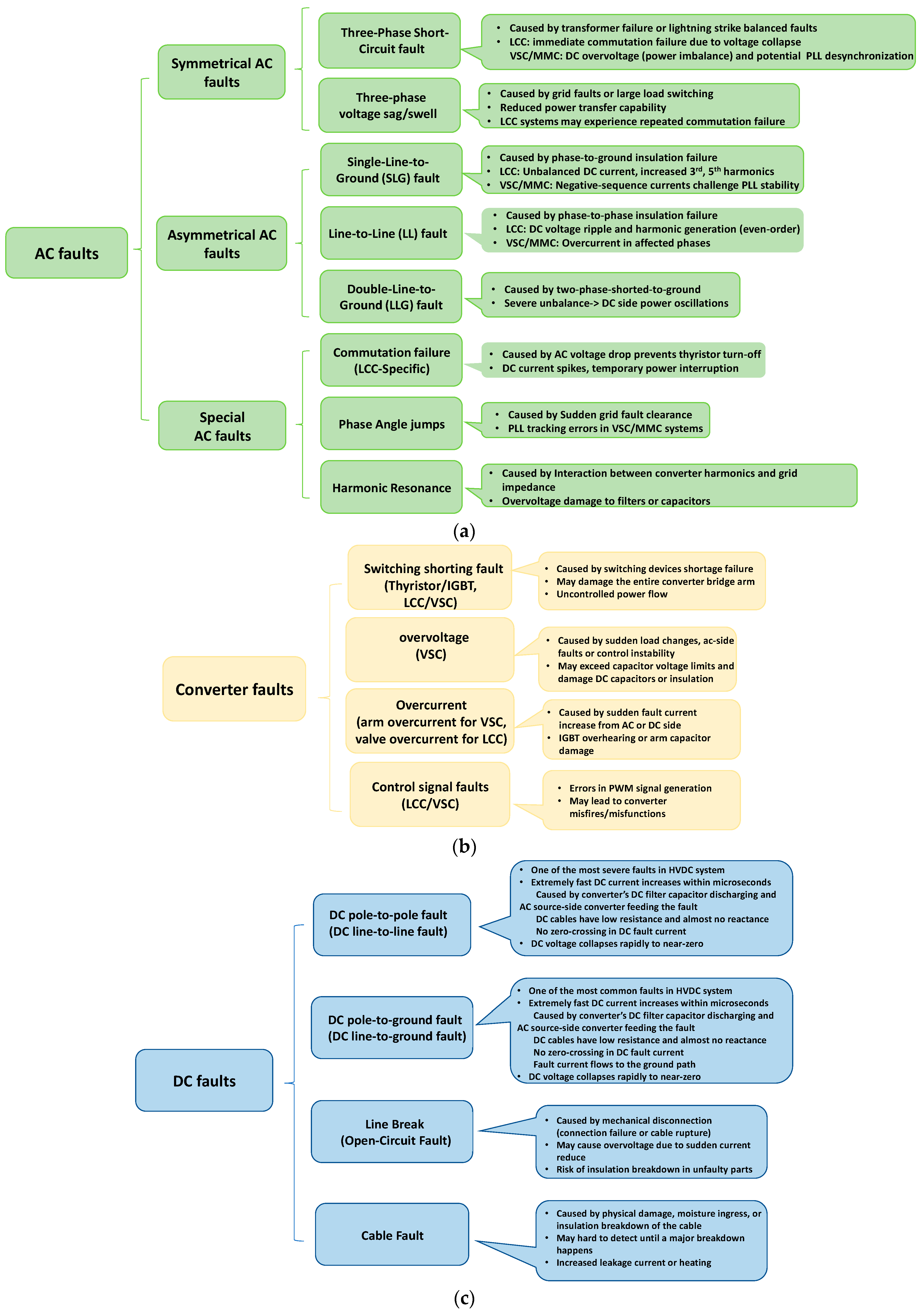
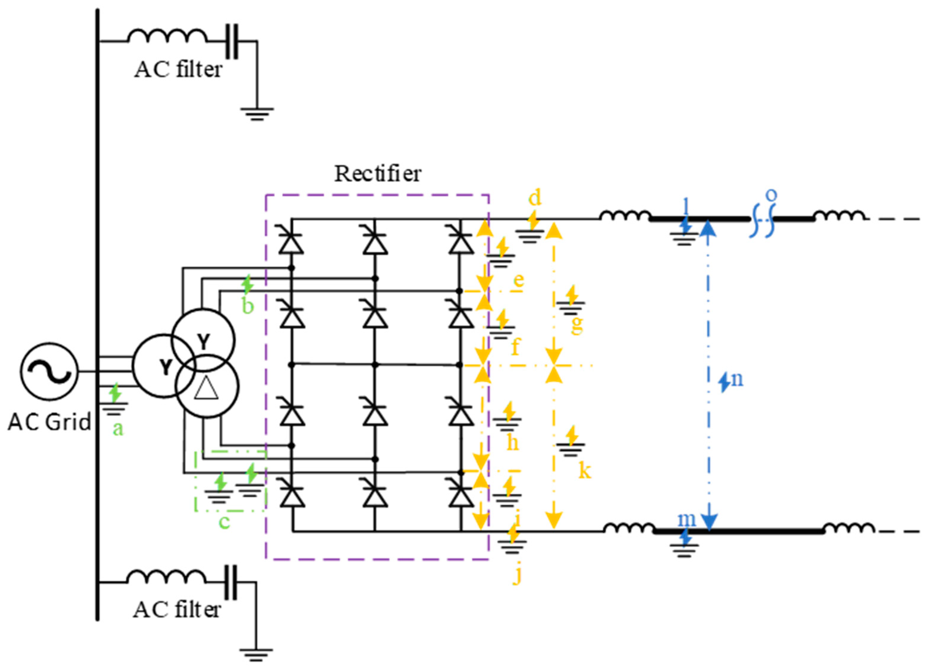
3. Fault Types in HVDC Grids
- AC faults
- 2.
- Converter faults
- 3.
- DC faults
4. Signal Processing Techniques in HVDC Fault Detection
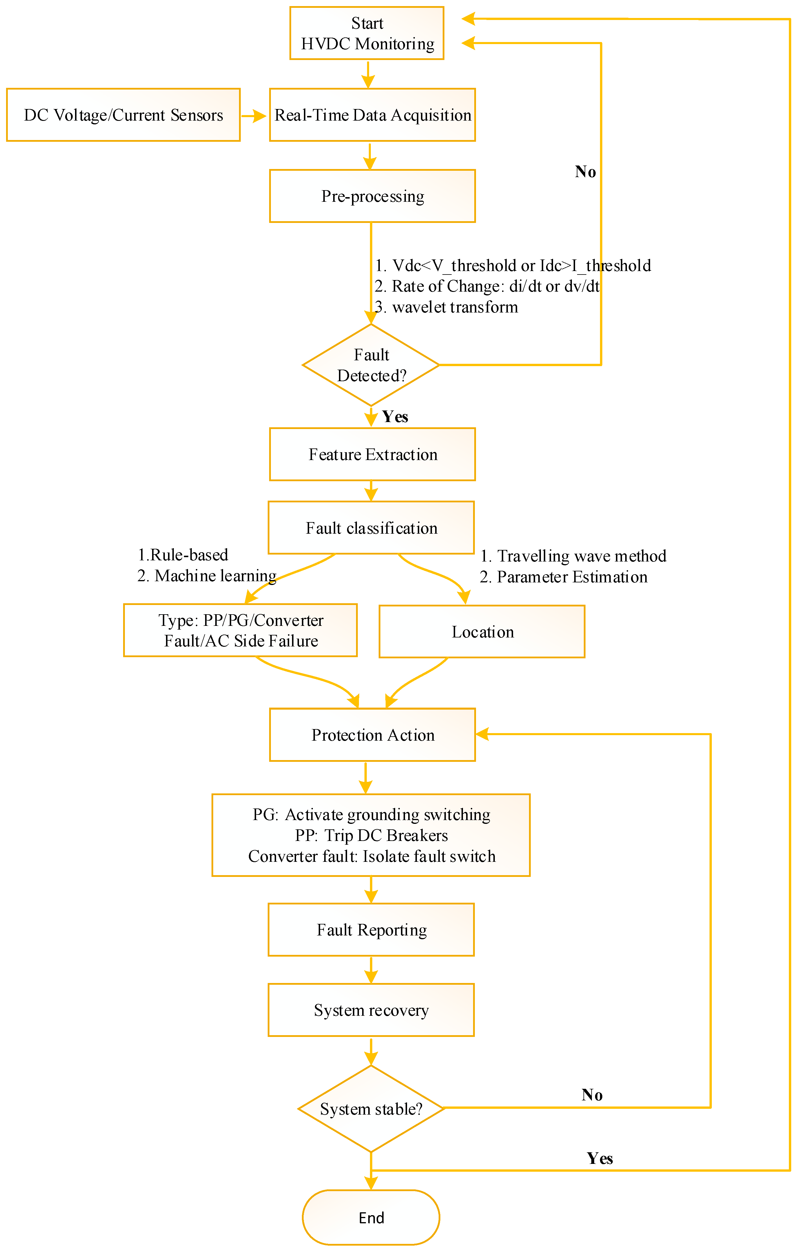
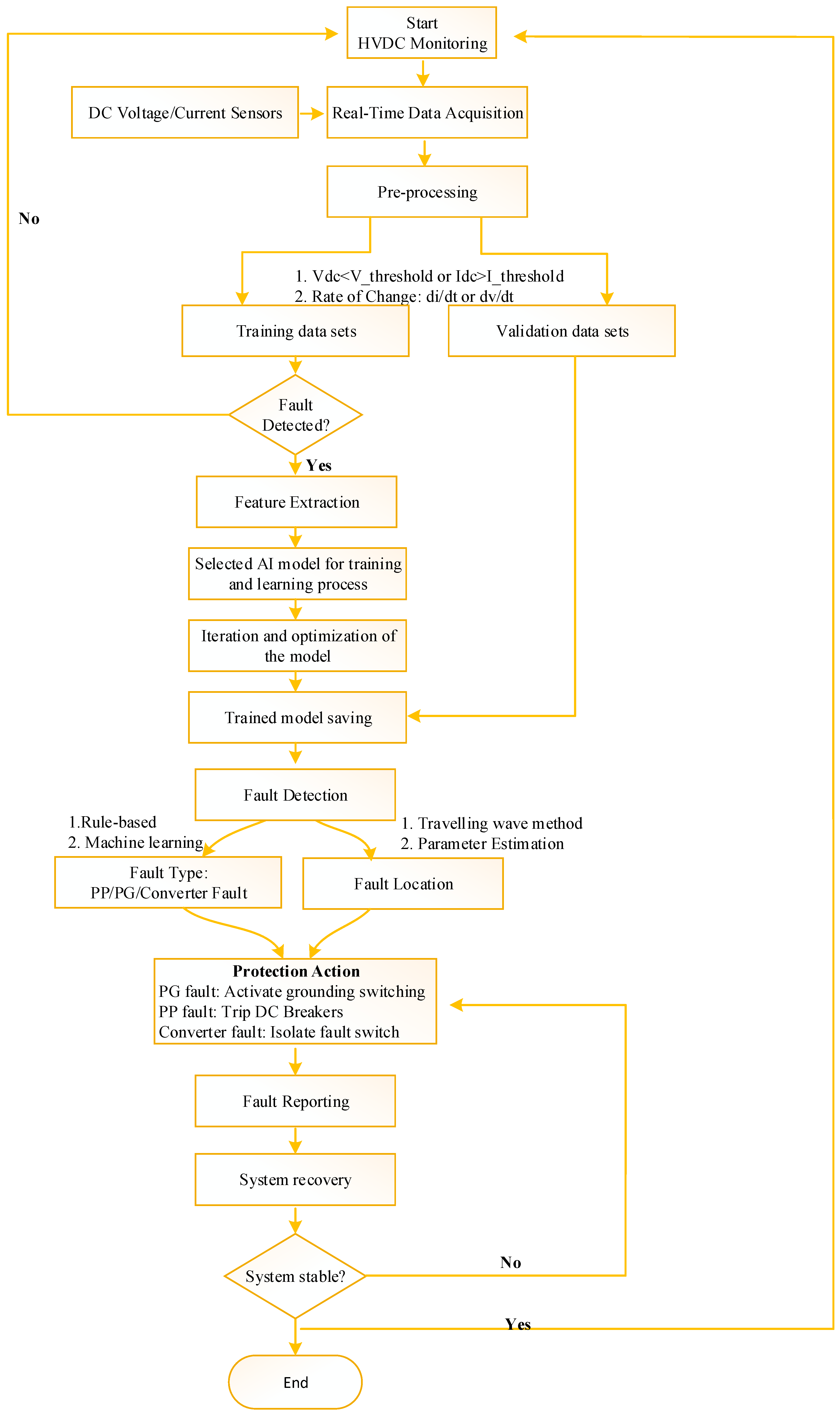
4.1. Fault Detection, Diagnosis, and Classification in HVDC Grids
4.1.1. Thermal
4.1.2. Pressure
4.1.3. Optical
4.1.4. Ultraviolet and Infrared Imaging
4.1.5. Acoustic
4.1.6. Electromagnetic Waves
4.2. Signal Processing Techniques
4.3. Signal Processing Applications for Fault Detection in HVDC Lines
5. Discussion and Prospects
5.1. Discussion
5.2. Future Research Directions
- Innovative Monitoring via Optical Sensor Networks
- ○
- We must develop magneto-optic glass sensors to replace traditional CT/PT, with increased bandwidth and integrate Optical Current Transducers (OCTs) and Optical Voltage Transducers (OVTs) for EMI-immune measurements.
- ○
- We must apply phase-sensitive Optical Time-Domain Reflectometry technology, which is an advanced technology used for the real-time monitoring of vibrations, pressure, and acoustic disturbances in DC lines without needing discrete sensors, reducing system costs.
- Digital Twin for HVDC Fault Detection
- Quantum Machine Learning for HVDC Fault Detection
6. Conclusions
- This paper has presented the developments of HVDC links in the world and the technological advancements from mercury-arc valves to IGBT-based converters, also summarizing the operational HVDC projects deployed in some technologically leading countries to showcase the state-of-the-art advancements.
- A comprehensive comparison of converter technologies (LCC, VSC and MMC) and pole configurations (monopolar, bipolar, homopolar, and MMC) of HVDC systems has been conducted.
- Different faults in HVDC systems including AC faults, converter faults, and DC faults have been summarized and compared, and the locations of major faults have been pinpointed.
- A comprehensive comparison of signal processing methods has been made, including time-domain, frequency-domain and time–frequency-domain methods, with case studies of references.
- Future research gaps have been discussed to improve reliability under diverse fault conditions in HVDC fault detection, classification, and protection.
Funding
Data Availability Statement
Conflicts of Interest
Abbreviations
| AC | Alternating Current |
| AI | Artificial Intelligence |
| ANFIS | Adaptive Neuro-Fuzzy Inference System |
| ANN | Artificial Neural Network |
| BLIMF | Band Limited Intrinsic Mode Functions |
| CNN | Convolutional Neural Network |
| CSC | Current Source Converter |
| CWT | Continuous Wavelet Transform |
| DC | Direct Current |
| DFT | Discrete Fourier Transform |
| DTWT | Dual Tree Complex Wavelet Transform |
| DWT | Discrete Wavelet Transform |
| EMD | Empirical Mode Decomposition |
| FFT | Fast Fourier Transform |
| FT | Fourier Transform |
| GAF | Gramian Angular Field |
| GaN | Gallium Nitride |
| HHT | Hilbert Huang Transform |
| HVAC | High-Voltage Alternating-Current |
| HVDC | High-Voltage Direct-Current |
| IMF | Intrinsic Mode Function |
| ITD | Intrinsic Time Decomposition |
| LCC | Line-Commutated Converter |
| LWT | Lifting Wavelet Transform |
| MLP | Multilayer Perceptron |
| MM | Mathematical Morphology |
| MMC | Modular Multilevel Converter |
| MODWT | Maximum-Overlap Discrete Wavelet Transform |
| PRC | Proper Rotating Component |
| PWM | Pulse Width Modulation |
| ROCOC | Rate of Change of Current |
| SiC | Silicon Carbide |
| ST | Stockwell Transform |
| STFT | Short-Time Fourier Transform |
| SVM | Support and Vector Machine |
| TEO | Total Energy Operator |
| TKEO | Teager–Kaiser Energy Operator |
| VMD | Variational Mode Decomposition |
| VSC | Voltage Sourced Converter |
| VSC-HVDC | Voltage-Source Converter–High-Voltage Direct-Current |
| WT | Wavelet Transform |
References
- McPherson, S.S. War of the Currents: Thomas Edison vs. Nikola Tesla; Twenty-First Century Books: Minneapolis, MN, USA, 2012. [Google Scholar]
- De Andrade, L.; de Leão, T.P. A Brief History of Direct Current in Electrical Power Systems. In Proceedings of the 2012 Third IEEE History of Electro-Technology Conference (HISTELCON), Pavia, Italy, 5–7 September 2012; IEEE: Piscataway, NJ, USA, 2013; pp. 1–6. [Google Scholar]
- Kim, C.; Sood, V.K.; Jang, G.; Lim, S.; Lee, S. Development of HVDC Technology. In HVDC Transmission; Wiley: Hoboken, NJ, USA, 2009; pp. 1–35. [Google Scholar]
- Guarnieri, M. The Alternating Evolution of DC Power Transmission. IEEE Ind. Electron. Mag. 2013, 7, 60–63. [Google Scholar] [CrossRef]
- Watson, N.R.; Watson, J.D. An Overview of HVDC Technology. Energies 2020, 13, 4342. [Google Scholar] [CrossRef]
- Tiku, D. Dc Power Transmission: Mercury-Arc to Thyristor HVdc Valves. IEEE Power Energy Mag. 2014, 12, 76–96. [Google Scholar] [CrossRef]
- Stan, A.; Costinaș, S.; Ion, G. Overview and Assessment of HVDC Current Applications and Future Trends. Energies 2022, 15, 1193. [Google Scholar] [CrossRef]
- Ludin, G.A.; Nakadomari, A.; Yona, A.; Mikkili, S.; Rangarajan, S.S.; Collins, E.R.; Senjyu, T. Technical and Economic Analysis of an HVDC Transmission System for Renewable Energy Connection in Afghanistan. Sustainability 2022, 14, 1468. [Google Scholar] [CrossRef]
- Oni, O.E.; Davidson, I.E.; Mbangula, K.N.I. A Review of LCC-HVDC and VSC-HVDC Technologies and Applications. In Proceedings of the EEEIC 2016-International Conference on Environment and Electrical Engineering, Florence, Italy, 7–10 June 2016; Institute of Electrical and Electronics Engineers Inc.: Piscataway, NJ, USA, 2016. [Google Scholar]
- Pierri, E.; Binder, O.; Hemdan, N.G.A.; Kurrat, M. Challenges and Opportunities for a European HVDC Grid. Renew. Sustain. Energy Rev. 2017, 70, 427–456. [Google Scholar] [CrossRef]
- Kalair, A.; Abas, N.; Khan, N. Comparative Study of HVAC and HVDC Transmission Systems. Renew. Sustain. Energy Rev. 2016, 59, 1653–1675. [Google Scholar] [CrossRef]
- Shah Ayobe, A.; Gupta, S. Comparative Investigation on HVDC and HVAC for Bulk Power Delivery. In Materials Today; Elsevier Ltd.: Amsterdam, The Netherlands, 2021; Volume 48, pp. 958–964. [Google Scholar]
- Pillay, C.J.; Kabeya, M.; Davidson, I.E. Transmission Systems: HVAC vs. HVDC. In Proceedings of the 5th NA International Conference on Industrial Engineering and Operations Management, Detroit, MI, USA, 10–14 August 2020; Durban University of Technology: Durban, KwaZulu-Natal, South Africa, 2020; Volume 10, pp. 2061–2077. [Google Scholar]
- Alam, M.T.; Rahaman, J.; Dhali, F.D.; Dhali, F.D. Technical Comparison of Modern HVAC and HVDC Transmission System Along with Cost Analysis. J. Control Instrum. Eng. 2022, 8, 10–19. [Google Scholar] [CrossRef]
- May, T.W.; Yeap, Y.M.; Ukil, A. Comparative Evaluation of Power Loss in HVAC and HVDC Transmission Systems. In Proceedings of the IEEE Region 10 Annual International Conference, Proceedings/TENCON, Singapore, 22–25 November 2016; Institute of Electrical and Electronics Engineers Inc.: Piscataway, NJ, USA, 2017; pp. 637–641. [Google Scholar]
- González, M.P.; Ríos, M.A. Comparison of HVDC-Grid and HVAC into Transmission Expansion Planning. In Proceedings of the 2018 IEEE ANDESCON., Medellín, Colombia, 22–24 August 2018; IEEE: Piscataway, NJ, USA, 2018; pp. 1–5. [Google Scholar]
- Zia Ud Din, S.; Hafeez, K.; Awan, A.B.; Uddin, S.Z.; Ullah, M.N.; Khan, Z.A. To Investigate Environmental Effects of HVDC versus HVAC Transmission Systems. J. Basic. Appl. Sci. Res 2013, 3, 840–843. [Google Scholar]
- Javed, U.; Mughees, N.; Jawad, M.; Azeem, O.; Abbas, G.; Ullah, N.; Chowdhury, M.S.; Techato, K.; Zaidi, K.S.; Tahir, U. A Systematic Review of Key Challenges in Hybrid Hvac–Hvdc Grids. Energies 2021, 14, 5451. [Google Scholar] [CrossRef]
- Saadeh, O.; Sba, B.A.; Dalala, Z.; Bashaireh, A. Comparative Performance Analysis of HVDC and HVAC Transmission Systems in the Presence of PV Generation: A Case Study Using the IEEE-5-Bus Network. In Proceedings of the 2023 AEIT HVDC International Conference, AEIT HVDC 2023, Rome, Italy, 25–26 May 2023; Institute of Electrical and Electronics Engineers Inc.: Piscataway, NJ, USA, 2023. [Google Scholar]
- Saadeh, O.; Abu Sba, B.; Dalala, Z. Power System Analysis of Moving from HVAC to HVDC in the Presence of Renewable Energy Resources. J. Electr. Comput. Eng. 2023, 2023, 8527308. [Google Scholar] [CrossRef]
- Ukil, A.; Yeap, Y.M.; Satpathi, K. Fault Analysis and Protection System Design for DC Grids; Springer: Berlin, Germany, 2020. [Google Scholar]
- Ergun, H.; van Hertem, D. Comparison of HVAC and HVDC Technologies. In HVDC Grids for Transmission of Electrical Energy: Offshore Grids and a Future Supergrid; Wiley-IEEE Press: Piscataway, NJ, USA, 2016; pp. 79–96. ISBN 9781119115243. [Google Scholar]
- Mazzanti, G.; Marzinotto, M.; Battaglia, A.; Villacci, D. The Problem of the Estimation of the End of Life of HVDC Cable Systems: The Influence of Laying Environment, Operational Duty and Cable Technologies. In Proceedings of the 2021 AEIT International Annual Conference, AEIT 2021, Milan, Italy, 4–8 October 2021; Institute of Electrical and Electronics Engineers Inc.: Piscataway, NJ, USA, 2021. [Google Scholar]
- Acaroğlu, H.; García Márquez, F.P. High Voltage Direct Current Systems through Submarine Cables for Offshore Wind Farms: A Life-Cycle Cost Analysis with Voltage Source Converters for Bulk Power Transmission. Energy 2022, 249, 123713. [Google Scholar] [CrossRef]
- Mazzanti, G. Issues and challenges for HVDC extruded cable systems. Energies 2021, 14, 4504. [Google Scholar] [CrossRef]
- EPRI. HVDC Overhead Line Performance Study (Report No. 1023191); Electric Power Research Institute: Palo Alto, CA, 2011. [Google Scholar]
- Arnold, G.W.; Li, X.; Perez, R.; Fortino, G.; Lumelsky, V.; Shafer, L.; Goldgof, D.; Mak, P.-I.; Wang, Z.; Hossain, E.; et al. HVDC GRIDS For Offshore and Supergrid of the Future; Wiley-IEEE Press: Hoboken, NJ, USA, 2016; ISBN 9781118859155. [Google Scholar]
- Park, K.H.; Kwon, I.; Lee, B.W. Calculation method of allowable continuous current for direct burial laying HVDC underground cable. Energies 2021, 14, 6431. [Google Scholar] [CrossRef]
- Hu, Y.; Lei, X.; Huang, T.; Zhang, Y. Frequency Coordinated Control for the Asynchronous Interconnected Power System with Multiple HVDC Links. IEEE Access 2022, 10, 108216–108225. [Google Scholar] [CrossRef]
- Imdadullah; Alamri, B.; Hossain, M.A.; Jamil Asghar, M.S. Electric Power Network Interconnection: A Review on Current Status, Future Prospects and Research Direction. Electronics 2021, 10, 2179. [Google Scholar] [CrossRef]
- Zhou, B.; Rao, H.; Wu, W.; Wang, T.; Hong, C.; Huang, D.; Yao, W.; Su, X.; Mao, T. Principle and Application of Asynchronous Operation of China Southern Power Grid. IEEE J. Emerg. Sel. Top. Power Electron. 2018, 6, 1032–1040. [Google Scholar] [CrossRef]
- Abedin, T.; Lipu, M.S.H.; Hannan, M.A.; Ker, P.J.; Rahman, S.A.; Yaw, C.T.; Tiong, S.K.; Muttaqi, K.M. Dynamic Modeling of Hvdc for Power System Stability Assessment: A Review, Issues, and Recommendations. Energies 2021, 14, 4829. [Google Scholar] [CrossRef]
- Zadehbagheri, M.; Ildarabadi, R.; Javadian, A.M. Optimal Power Flow in the Presence of HVDC Lines Along with Optimal Placement of FACTS in Order to Power System Stability Improvement in Different Conditions: Technical and Economic Approach. IEEE Access 2023, 11, 57745–57771. [Google Scholar] [CrossRef]
- Nie, Y.; Zhang, G.; Duan, H. An Interconnected Panorama of Future Cross-Regional Power Grid: A Complex Network Approach. Resour. Policy 2020, 67, 101692. [Google Scholar] [CrossRef]
- Hussein, I.I.; Essallah, S.; Khedher, A. The Impact of HVDC on the Current and Future Energy Markets. Int. J. Electr. Electron. Eng. Telecommun. 2022, 11, 426–434. [Google Scholar] [CrossRef]
- Li, C.; Hu, X.; Guo, J.; Liang, J. The DC Grid Reliability and Cost Evaluation with Zhoushan Five-Terminal HVDC Case Study. In Proceedings of the Universities Power Engineering Conference, Stoke on Trent, UK, 1–4 September 2015; IEEE Computer Society: Piscataway, NJ, USA, 2015. [Google Scholar]
- Mitra, S.; Pandaraboyana, D.K.; Arulvendhan, K.; Srinivasan, J.D. HVDC in Indian Power Sector. Int. J. Recent Technol. Eng. 2019, 8, 1S4. [Google Scholar]
- Kerdphol, T.; Matsukawa, Y.; Watanabe, M.; Mitani, Y. Application of PMUs to Monitor Large-Scale PV Penetration Infeed on Frequency of 60 Hz Japan Power System: A Case Study from Kyushu Island. Electr. Power Syst. Res. 2020, 185, 106393. [Google Scholar] [CrossRef]
- Sato, T.; Nishiuchi, M.; Saito, S.; Suzuki, M.; Nosaka, N.; Yamakawa, T. Kii-Channel HVDC System. IEEJ Trans. Electr. Electron. Eng. 2009, 4, 22–23. [Google Scholar] [CrossRef]
- Alhelou, H.H.; Bahrani, B.; Ma, J.; Hill, D.J. Australia’s Power System Frequency: Current Situation, Industrial Challenges, Efforts, and Future Research Directions. IEEE Trans. Power Syst. 2024, 39, 5204–5218. [Google Scholar] [CrossRef]
- Smith, M. Culture shock: The legacy of the 1960s power generation schemes in Aotearoa New Zealand. Archit. Hist. Aotearoa 2022, 19, 61–82. [Google Scholar] [CrossRef]
- Shuai, Z.; He, D.; Xiong, Z.; Lei, Z.; John Shen, Z. Comparative Study of Short-Circuit Fault Characteristics for VSC-Based DC Distribution Networks with Different Distributed Generators. IEEE J. Emerg. Sel. Top. Power Electron. 2019, 7, 528–540. [Google Scholar] [CrossRef]
- Li, Y.; Li, J.; Wu, G.; Xiong, L.; Jia, K.; Xu, Z. DC Fault Analysis Models of Three Converter Topologies Considering Control Effects. IEEE Trans. Ind. Electron. 2020, 67, 9480–9491. [Google Scholar] [CrossRef]
- Pourmirasghariyan, M.; Zarei, S.F.; Hamzeh, M. DC-System Grounding: Existing Strategies, Performance Analysis, Functional Characteristics, Technical Challenges, and Selection Criteria—A Review. Electr. Power Syst. Res. 2022, 206, 107769. [Google Scholar] [CrossRef]
- Abbasipour, M.; Liang, X.; Mitolo, M. Power Electronics in HVDC Transmission Systems. In Smart and Power Grid Systems–Design Challenges and Paradigms; River Publishers: Norwell, MA, USA, 2023; pp. 21–82. [Google Scholar]
- Khazaei, J.; Idowu, P.; Asrari, A.; Shafaye, A.B.; Piyasinghe, L. Review of HVDC Control in Weak AC Grids. Electr. Power Syst. Res. 2018, 162, 194–206. [Google Scholar] [CrossRef]
- Bakas, P.; Okazaki, Y.; Shukla, A.; Patro, S.K.; Ilves, K.; Dijkhuizen, F.; Nami, A. Review of Hybrid Multilevel Converter Topologies Utilizing Thyristors for HVDC Applications. IEEE Trans. Power Electron. 2021, 36, 174–190. [Google Scholar] [CrossRef]
- Lebre, J.R.; Portugal, P.M.M.; Watanabe, E.H. Hybrid HVDC (H2VDC) System Using Current and Voltage Source Converters. Energies 2018, 11, 1323. [Google Scholar] [CrossRef]
- Constantin, A.; Dinculescu, R.N. Impact in the Power System Following the Replacement of HVAC with HVDC Lines in Dobrogea Area. In Proceedings of the 2019 8th International Conference on Modern Power Systems (MPS), Bucharest, Romania, 21–23 May 2019; IEEE: Piscataway, NJ, USA, 2019; pp. 1–5. [Google Scholar]
- Sanchez Garciarivas, R.; Rasilla Gonzalez, D.; Navarro, J.A.; Soriano, L.A.; Rubio, J.d.J.; Gomez, M.V.; Garcia, V.; Pacheco, J. Vsc-Hvdc and Its Applications for Black Start Restoration Processes. Appl. Sci. 2021, 11, 5648. [Google Scholar] [CrossRef]
- Chivite-Zabalza, J.; Trainer, D.R.; Nicholls, J.C.; Davidson, C.C. Balancing Algorithm for a Self-Powered High-Voltage Switch Using Series-Connected IGBTs for HVDC Applications. IEEE Trans. Power Electron. 2019, 34, 8481–8490. [Google Scholar] [CrossRef]
- Millan, J.; Godignon, P.; Perpina, X.; Perez-Tomas, A.; Rebollo, J. A Survey of Wide Bandgap Power Semiconductor Devices. IEEE Trans. Power Electron. 2014, 29, 2155–2163. [Google Scholar] [CrossRef]
- Casady, J.B.; Pala, V.; Lichtenwalner, J.D.; Brunt, E.V. New Generation 10kV SiC Power MOSFET and Diodes for Industrial Applications. In Proceedings of the PCIM Europe 2015, International Exhibition and Conference for Power Electronics, Intelligent Motion, Renewable Energy and Energy Management, Nuremberg, Germany, 19–20 May 2015; IEEE: Piscataway, NJ, USA, 2015. ISBN 9783800739240. [Google Scholar]
- Lagier, T.; Ladoux, P.; Dworakowski, P. Potential of Silicon Carbide MOSFETs in the DC/DC Converters for Future HVDC Offshore Wind Farms. High Volt. 2017, 2, 233–243. [Google Scholar] [CrossRef]
- Ishii, Y.; Jimichi, T. Verification of SiC Based Modular Multilevel Cascade Converter (MMCC) for HVDC Transmission Systems. Ph.D. Thesis, Ecole Centrale de Lille, Villeneuve-d’Ascq, France, 2017. [Google Scholar]
- Shinoda, K. Control and Energy Management of MMC-Based Multi-Terminal HVDC Grids. Ph.D. Thesis, École Centrale de Lille, Villeneuve-d’Ascq, France, 2017. [Google Scholar]
- He, Y.; Xiang, W.; Ni, B.; Lu, X.; Wen, J. Impact of Strength and Proximity of Receiving AC Systems on Cascaded LCC-MMC Hybrid HVDC System. IEEE Trans. Power Deliv. 2022, 37, 880–892. [Google Scholar] [CrossRef]
- Cheah-Mane, M.; Song, J.; Ferrer-San-Jose, R.; Prieto-Araujo, E.; Gomis-Bellmunt, O. Analysis of hybrid LCC-VSC HVDC Transmission System Configurations. In Proceedings of the 15th IET International Conference on AC and DC Power Transmission, Coventry, UK, 5–7 February 2019; IEEE: Piscataway, NJ, USA, 2019. [Google Scholar]
- Xiao, H.; Sun, K.; Pan, J.; Liu, Y. Operation and Control of Hybrid HVDC System with LCC and Full-Bridge MMC Connected in Parallel. IET Gener. Transm. Distrib. 2020, 14, 1344–1352. [Google Scholar] [CrossRef]
- Li, X.; Teng, Y.; Liu, L.; Fang, G. A Power Allocation Strategy for DC Line Fault in Serial Hybrid LCC-MMC HVDC System. IEEE Access 2022, 10, 84267–84278. [Google Scholar] [CrossRef]
- Leterme, W.; Tielens, P.; De Boeck, S.; Van Hertem, D. Overview of Grounding and Configuration Options for Meshed HVDC Grids. IEEE Trans. Power Deliv. 2014, 29, 2467–2475. [Google Scholar] [CrossRef]
- Dey, S.; Bhattacharya, T. Monopolar Operation of Modular Multilevel DC-DC Converter Based Hybrid Bipolar HVDC Links. In Proceedings of the 2021 IEEE Texas Power and Energy Conference, TPEC 2021, College Station, TX, USA, 2–5 February 2021; Institute of Electrical and Electronics Engineers Inc.: Piscataway, NJ, USA, 2021. [Google Scholar]
- Kutay, M.; Usman, A. A Survey on HVDC Power Transmission Systems. Bilecik. Şeyh. Edebali. Üniversitesi. Fen. Bilim. Derg. 2020, 7, 1170–1181. [Google Scholar] [CrossRef]
- Zhao, Q.; García-González, J.; García-Cerrada, A.; Renedo, J.; Rouco, L. HVDC in the Future Power Systems. In Transmission Expansion Planning: The Network Challenges of the Energy Transition; Springer International Publishing: Cham, Switzerland, 2020; pp. 117–151. [Google Scholar]
- Singh, S. Why and Why Not to Go for HVDC? IOSR J. Electr. Electron. Eng. 2015, 10, 38–43. [Google Scholar]
- HVDC. Links in System Operations; ENTSO-E: Brussels, Belgium, 2019. [Google Scholar]
- Amamra, S.A.; Colas, F.; Guillaud, X.; Rault, P.; Nguefeu, S. Laboratory Demonstration of a Multiterminal VSC-HVDC Power Grid. IEEE Trans. Power Deliv. 2017, 32, 2339–2349. [Google Scholar] [CrossRef]
- Ashouri, M.; Bak, C.L.; Faria Da Silva, F. A Review of the Protection Algorithms for Multi-Terminal VCD-HVDC Grids. In Proceedings of the IEEE International Conference on Industrial Technology, Lyon, France, 20–22 February 2018; Institute of Electrical and Electronics Engineers Inc.: Piscataway, NJ, USA, 2018; pp. 1673–1678. [Google Scholar]
- Cai, D.; Zhou, K.; Wang, W.; Liu, H.; Cao, K.; Wang, Y. Influence of Back-to-back VSC-HVDC Project on the Operation Characteristics of Hubei Power Grid. J. Eng. 2017, 2017, 801–805. [Google Scholar] [CrossRef]
- Chen, Q.; Li, Q.; Wu, J.; He, J.; Mao, C.; Li, Z.; Yang, B. State Monitoring and Fault Diagnosis of HVDC System via KNN Algorithm with Knowledge Graph: A Practical China Power Grid Case. Sustainability 2023, 15, 3717. [Google Scholar] [CrossRef]
- Jawad, R.S.; Abid, H. HVDC Fault Detection and Classification with Artificial Neural Network Based on ACO-DWT Method. Energies 2023, 16, 1064. [Google Scholar] [CrossRef]
- Nagar, K.; Shah, M. A Review on Different ANN Based Fault Detection Techniques for HVDC Systems. Int. J. Innov. Res. Eng. Manag. 2016, 3, 477–481. [Google Scholar] [CrossRef]
- Khaimar, A.K.; Shah, P.J. Study of Various Types of Faults in HVDC Transmission System. In Proceedings of the International Conference on Global Trends in Signal Processing, Information Computing and Communication, ICGTSPICC, Jalgaon, India, 22–24 December 2016; Institute of Electrical and Electronics Engineers Inc.: Piscataway, NJ, USA, 2017; pp. 480–484. [Google Scholar]
- Najafzadeh, M.; Pouladi, J.; Daghigh, A.; Beiza, J.; Abedinzade, T. Fault Detection, Classification and Localization Along the Power Grid Line Using Optimized Machine Learning Algorithms. Int. J. Comput. Intell. Syst. 2024, 17, 49. [Google Scholar] [CrossRef]
- Mustari, M.R.; Hashim, M.N.; Osman, M.K.; Ahmad, A.R.; Ahmad, F.; Ibrahim, M.N. Fault Location Estimation on Transmission Lines Using Neuro-Fuzzy System. In Procedia Computer Science; Elsevier B.V.: Amsterdam, The Netherlands, 2019; Volume 163, pp. 591–602. [Google Scholar]
- Khalid, S.; Yousaf, M.Z.; Luo, M.; Wenhuan, W.; Mirsaeidi, S.; Muttaqi, K.M. Evaluation of Electrical and Thermal Stresses in Conventional and Solid-State Fault Current Limiter-Based Hybrid HVDC Circuit Breaker. In Proceedings of the 2023 IEEE International Conference on Energy Technologies for Future Grids, ETFG 2023, Wollongong, Australia, 3–6 December 2023; Institute of Electrical and Electronics Engineers Inc.: Piscataway, NJ, USA, 2023. [Google Scholar]
- Hahn, F.; Andresen, M.; Buticchi, G.; Liserre, M. Thermal Analysis and Balancing for Modular Multilevel Converters in HVDC Applications. IEEE Trans. Power Electron. 2018, 33, 1985–1996. [Google Scholar] [CrossRef]
- He, J.; Yu, Z.; Zeng, R.; Zhang, B. Vibration and Audible Noise Characteristics of AC Transformer Caused by HVDC System under Monopole Operation. IEEE Trans. Power Deliv. 2012, 27, 1835–1842. [Google Scholar] [CrossRef]
- Rose, A.H.; Amano, R.; Hadley, E. Digital Optical CT Application to HVDC Earthing Line Fault Measurements. IEEE Trans. Power Deliv. 2021, 36, 2238–2240. [Google Scholar] [CrossRef]
- Liu, H.; Zhou, C.; Shen, Q.; Yang, B.; Sun, X.; Huang, Z.; Liu, R.; Liu, C. Flashover Characteristics of Plastic Cloth on ±800 KV HVDC Transmission Line. In Proceedings of the IOP Conference Series: Earth and Environmental Science; IOP Conference Series Earth Environment Science: Bristol, UK, 2019; Volume 227, p. 32006. [Google Scholar]
- Sirui, Z.; Rui, L.; Xiang, R.; Liang, W.; Guanping, L.; Ling, R. Extraction Method of PD Acoustic Emission Signal for Solid Insulated HVDC Equipment. In Proceedings of the 6th International Conference on HVDC, HVDC 2024, Urumqi, China, 8–9 August 2024; Institute of Electrical and Electronics Engineers Inc.: Piscataway, NJ, USA, 2024; pp. 59–64. [Google Scholar]
- Zhu, K.; Lee, W.K.; Pong, P.W.T. Non-Contact Voltage Monitoring of HVDC Transmission Lines Based on Electromagnetic Fields. IEEE Sens. J. 2019, 19, 3121–3129. [Google Scholar] [CrossRef]
- Zhu, K.; Lee, W.K.; Pong, P.W.T. Fault-Line Identification of HVDC Transmission Lines by Frequency-Spectrum Correlation Based on Capacitive Coupling and Magnetic Field Sensing. IEEE Trans. Magn. 2018, 54, 4001805. [Google Scholar] [CrossRef]
- Pazoki, M.; Yadav, A.; Abdelaziz, A.Y. Pattern-Recognition Methods for Decision-Making in Protection of Transmission Lines. In Decision Making Applications in Modern Power Systems; Elsevier: Amsterdam, The Netherlands, 2019; pp. 441–472. ISBN 9780128164457. [Google Scholar]
- Sidhu, T.; Bhajla, B.; Das, S. Numerical Algorithms for Protection and Metering Devices; Elsevier: Amsterdam, The Netherlands, 2023; pp. 45–87. [Google Scholar]
- Aleem, S.A.; Shahid, N.; Naqvi, I.H. Methodologies in Power Systems Fault Detection and Diagnosis. Energy Syst. 2015, 6, 85–108. [Google Scholar] [CrossRef]
- Li, D.; Ukil, A. Empirical Mode Decomposition Based DC Fault Detection Method in Multi-Terminal DC System. In Proceedings of the IEEE Power and Energy Society General Meeting, Montreal, QB, Canada, 2–6 August 2020; IEEE: Piscataway, NJ, USA. [Google Scholar]
- Damine, Y.; Bessous, N.; Pusca, R.; Megherbi, A.C.; Romary, R.; Sbaa, S. A New Bearing Fault Detection Strategy Based on Combined Modes Ensemble Empirical Mode Decomposition, KMAD, and an Enhanced Deconvolution Process. Energies 2023, 16, 2604. [Google Scholar] [CrossRef]
- Gnanamalar, A.J.; Bhavani, R.; Arulini, A.S.; Veerraju, M.S. CNN–SVM Based Fault Detection, Classification and Location of Multi-Terminal VSC–HVDC System. J. Electr. Eng. Technol. 2023, 18, 3335–3347. [Google Scholar] [CrossRef]
- Ashouri, M.; Faria da Silva, F.; Leth Bak, C. Analysis and Validation of Mathematical Morphology Filters for Single-Ended Fault Localization in VSC-HVDC Links. Electr. Eng. 2021, 103, 1583–1596. [Google Scholar] [CrossRef]
- Li, Y.; Zuo, M.J.; Lin, J.; Liu, J. Fault Detection Method for Railway Wheel Flat Using an Adaptive Multiscale Morphological Filter. Mech. Syst. Signal Process 2017, 84, 642–658. [Google Scholar] [CrossRef]
- Adly, A.R.; Abdel Aleem, S.H.E.; Elsadd, M.A.; Ali, Z.M. Wavelet Packet Transform Applied to a Series-Compensated Line: A Novel Scheme for Fault Identification. Measurement 2020, 151, 107156. [Google Scholar] [CrossRef]
- Wang, Y.; Li, J.; Pei, Y.; Ma, Z.; Jia, Y.; Wei, Y.C. An Adaptive High-Voltage Direct Current Detection Algorithm Using Cognitive Wavelet Transform. Inf. Process. Manag. 2022, 59, 102867. [Google Scholar] [CrossRef]
- Imani, A.; Moravej, Z.; Pazoki, M. A Novel MODWT-Based Fault Detection and Classification Scheme in VSC-HVDC Transmission Line. Electr. Power Syst. Res. 2023, 221, 109434. [Google Scholar] [CrossRef]
- Isasare, T.V.; Majumdar, D.D. Application of Wavelet Transform in Power System. Int. J. Eng. Res. Technol. IJERT 2016, 4, 212–216. [Google Scholar]
- Patnaik, B.; Mishra, M.; Bansal, R.C.; Jena, R.K. MODWT-XGBoost Based Smart Energy Solution for Fault Detection and Classification in a Smart Microgrid. Appl. Energy 2021, 285, 116457. [Google Scholar] [CrossRef]
- Chawda, G.S.; Shaik, A.G.; Shaik, M.; Padmanaban, S.; Holm-Nielsen, J.B.; Mahela, O.P.; Kaliannan, P. Comprehensive Review on Detection and Classification of Power Quality Disturbances in Utility Grid with Renewable Energy Penetration. IEEE Access 2020, 8, 146807–146830. [Google Scholar] [CrossRef]
- Ying, C.; Songhai, F.; Qiaomei, W.; Tianbao, W.; Lei, L.; Xiaomin, M.; Yiyu, G. A Novel Fault Identification Method for HVDC Transmission Line Based on Stransform Multi-Scale Area. In Proceedings of the 2020 5th International Conference on Computational Intelligence and Applications, ICCIA 2020, Beijing, China, 19–21 June 2020; Institute of Electrical and Electronics Engineers Inc.: Piscataway, NJ, USA, 2020; pp. 199–205. [Google Scholar]
- Goyal, D.; Pabla, B.S. Condition Based Maintenance of Machine Tools-A Review. CIRP J. Manuf. Sci. Technol. 2015, 10, 24–35. [Google Scholar] [CrossRef]
- Li, D.; Ukil, A.; Satpathi, K.; Yeap, Y.M. Improved S Transform-Based Fault Detection Method in Voltage Source Converter Interfaced DC System. IEEE Trans. Ind. Electron. 2021, 68, 5024–5035. [Google Scholar] [CrossRef]
- Liu, H.; Chen, C. Data Processing Strategies in Wind Energy Forecasting Models and Applications: A Comprehensive Review. Appl. Energy. 2019, 249, 392–408. [Google Scholar] [CrossRef]
- Huai, Q.; Liu, K.; Hooshyar, A.; Ding, H.; Chen, K.; Liang, Q. Single-Ended Line Fault Location Method for Multi-Terminal HVDC System Based on Optimized Variational Mode Decomposition. Electr. Power Syst. Res. 2021, 194, 107054. [Google Scholar] [CrossRef]
- Li, F.; Li, R.; Tian, L.; Chen, L.; Liu, J. Data-Driven Time-Frequency Analysis Method Based on Variational Mode Decomposition and Its Application to Gear Fault Diagnosis in Variable Working Conditions. Mech Syst Signal Process 2019, 116, 462–479. [Google Scholar] [CrossRef]
- Lacerda, V.A.; Monaro, R.M.; Campos-Gaona, D.; Coury, D.V.; Anaya-Lara, O. Distance Protection Algorithm for Multiterminal HVDC Systems Using the Hilbert-Huang Transform. IET Gener. Transm. Distrib. 2020, 14, 3022–3032. [Google Scholar] [CrossRef]
- Liu, Y.; Guo, H.; Zhu, G.; Yu, G. Single-Pole Fault Protection for MMC-HVDC Transmission Line Based on Improved Transient-Extracting Transform. Int. Trans. Electr. Energy Syst. 2021, 31, e13254. [Google Scholar] [CrossRef]
- Elgeziry, M.Z.; Elsadd, M.A.; Elkalashy, N.I.; Kawady, T.A.; Taalab, A.M.I. AC Spectrum Analysis for Detecting DC Faults on HVDC Systems. In Proceedings of the 2017 Nineteenth International Middle East Power Systems Conference (MEPCON), Cairo, Egypt, 19–21 December 2017; IEEE: Piscataway, NJ, USA, 2017; pp. 708–715. [Google Scholar]
- Nadeem, M.H.; Zheng, X.; Tai, N.; Gul, M.; Yu, M.; He, Y. Non-Communication Based Protection Scheme Using Transient Harmonics for Multi-Terminal HVDC Networks. Int. J. Electr. Power Energy Syst. 2021, 127, 106636. [Google Scholar] [CrossRef]
- Ding, C.; Wang, Z.; Ding, Q.; Yuan, Z. Convolutional Neural Network Based on Fast Fourier Transform and Gramian Angle Field for Fault Identification of HVDC Transmission Line. Sustain. Energy Grids Netw. 2022, 32, 100888. [Google Scholar] [CrossRef]
- Farkhani, J.S.; Niaki, S.H.A.; Ma, K.; Bak, C.L.; Chen, Z. A Fast Fault Detection for Multi-Terminal VSC HVDC Transmission Lines. J. Electr. Comput. Eng. Res. 2023, 3, 24–29. [Google Scholar]
- Ahmadi-Khaneghahi, Y.; Shahabi, M.; Barforoushi, T.; Ahmadi, I. A Fast and Robust Local-Based Protection Algorithm Based on the High-Frequency Transient for HVDC Grid. IEEE Trans. Power Deliv. 2023, 38, 2531–2540. [Google Scholar] [CrossRef]
- Ashouri, M.; Silva, F.F.D.; Bak, C.L. Application of Short-time Fourier Transform for Harmonic-based Protection of Meshed VSC-MTDC Grids. J. Eng. 2019, 2019, 1439–1443. [Google Scholar] [CrossRef]
- Psaras, V.; Tzelepis, D.; Vozikis, D.; Adam, G.P.; Burt, G. Non-Unit Protection for HVDC Grids: An Analytical Approach for Wavelet Transform-Based Schemes. IEEE Trans. Power Deliv. 2021, 36, 2634–2645. [Google Scholar] [CrossRef]
- Kaur, J.; Jayasooriya, M.; Iqbal, M.N.; Daniel, K.; Shabbir, N.; Peterson, K. Fault Detection and Protection Strategy for Multi-Terminal HVDC Grids Using Wavelet Analysis. Energies 2025, 18, 1147. [Google Scholar] [CrossRef]
- Farkhani, J.S.; Celik, O.; Ma, K.; Bak, C.L.; Chen, Z. VSC MT-HVDC Fault Identification Based on the VMD-TEO and Artificial Neural Network. In Proceedings of the 2023 2nd International Conference on Power Systems and Electrical Technology, PSET 2023, Milan, Italy, 25–27 August 2023; Institute of Electrical and Electronics Engineers Inc.: Piscataway, NJ, USA, 2023; pp. 219–224. [Google Scholar]
- Liu, S.; Han, K.; Li, H.; Zhang, T.; Chen, F. A Two-Terminal Directional Protection Method for HVDC Transmission Lines of Current Fault Component Based on Improved VMD-Hilbert Transform. Energies 2023, 16, 6987. [Google Scholar] [CrossRef]
- Man, W.; Bei, X.; Zhang, Z. A Protection Method of VSC-HVDC Cables Based on Generalized S-Transform. Energy Power 2021, 13, 1–10. [Google Scholar] [CrossRef]
- Ashouri, M.; Da Silva, F.F.; Bak, C.L. A Pilot Protection Scheme for VSC-MTDC Grids Based on Polarity Comparison Using a Combined Morphological Technique. Electr. Eng. 2022, 104, 1395–1411. [Google Scholar] [CrossRef]
- Jamali, S.; Mirhosseini, S.S. Protection of Transmission Lines in Multi-Terminal HVDC Grids Using Travelling Waves Morphological Gradient. Int. J. Electr. Power Energy Syst. 2019, 108, 125–134. [Google Scholar] [CrossRef]
- Imani, A.; Moravej, Z.; Pazoki, M. A Novel Time-Domain Method for Fault Detection and Classification in VSC-HVDC Transmission Lines. Int. J. Electr. Power Energy Syst. 2022, 140, 108056. [Google Scholar] [CrossRef]
- Li, D.; Ukil, A.; Satpathi, K.; Yeap, Y.M. Hilbert-Huang Transform Based Transient Analysis in Voltage Source Converter Interfaced Direct Current System. IEEE Trans. Ind. Electron. 2021, 68, 11014–11025. [Google Scholar] [CrossRef]
- Radwan, M.; Azad, S.P. A Single-Ended Protection Scheme for Multi-Terminal HVDC Grids Based on Hilbert-Huang Transform. In Proceedings of the IEEE Power and Energy Society General Meeting, Orlando, FL, USA, 16–20 July 2023; IEEE Computer Society: Piscataway, NJ, USA, 2023. [Google Scholar]
- Zhang, T.; Han, K.; Li, H.; Liu, S.; Chen, F. Two Terminals Protection Method for HVDC Transmission Lines Based on Maximal Overlap Discrete Wavelet Transform and Cross-Correlation Coefficient of Traveling Wave. Energy Rep. 2023, 9, 1133–1148. [Google Scholar] [CrossRef]
- Moravej, Z.; Imani, A.; Pazoki, M. Artificial Intelligence Application for HVDC Protection. In Artificial Intelligence Applications in Electrical Transmission and Distribution Systems Protection; CRC Press: Boca Raton, FL, USA, 2021; pp. 387–418. [Google Scholar]
- Wang, Q.; Yu, Y.; Ahmed, H.O.A.; Darwish, M.; Nandi, A.K. Open-Circuit Fault Detection and Classification of Modular Multilevel Converters in High Voltage Direct Current Systems (Mmc-Hvdc) with Long Short-Term Memory (Lstm) Method. Sensors 2021, 21, 4159. [Google Scholar] [CrossRef]
- Jawad, R.S.; Abid, H. Fault Detection in HVDC System with Gray Wolf Optimization Algorithm Based on Artificial Neural Network. Energies 2022, 15, 7775. [Google Scholar] [CrossRef]
- Mishra, M.; Pragati, A.; Gadanayak, D.A.; Parida, T. Signal Processing and Artificial Intelligence Based HVDC Network Protection: A Systematic and State-up-the-Art Review. e-Prime Adv. Electr. Eng. Electron. Energy 2024, 8, 100606. [Google Scholar] [CrossRef]


| Technology | Year | Name of Projects | Rated Power (MW) | Rated Voltage (kV) | Rated Current (A) | Total Line (km) |
|---|---|---|---|---|---|---|
| Mercury (1954–1975) | 1954 | Gotland (Sweden) | 20 | 100 | 200 | 96 |
| 1961 | Cross Channel (United Kingdom, France) | 160 | ±100 | 800 | 65 | |
| 1965 | Volgograd-Donbass (USSR) | 720 | ±400 | 900 | 472 | |
| 1965 | Benmore–Haywards (New Zealand) | 600 | ±250 | 1200 | 609 | |
| 1965 | Konti–Skan (Denmark, Sweden) | 250 | ±250 | 1000 | 180 | |
| 1965 | Sakuma (Japan) | 300 | 2 × 125 | 1200 | 0 | |
| 1967 | Sardinia (Italy) | 200 | 200 | 1000 | 413 | |
| 1968 | Vancouver, Pole 1 (Canada) | 312 | ±260 | 1200 | 73 | |
| 1970 | Pacific Intertie (United States) | 1440 | ±400 | 1800 | 1354 | |
| 1976 | Nelson River Bipole 1 (Canada) | 1620 | ±450 | 1800 | 890 | |
| 1975 | Kingsnorth (United Kingdom) | 640 | ±266 | 1200 | 82 | |
| Thyristor Valves (1972–Present) | 1972 | Eel River (Canada) | 320 | 2 × 80 | 2000 | 0 |
| 1975 | Cabora-Bassa (Mozambique, South Africa) | 960 | ±266 | 1800 | 1420 | |
| 2011 | BritNed (UK–Netherlands) | 1000 | ±450 | 1100 | 260 | |
| 2014 | Xiluodu–Zhejiang (China) | 8000 | ±800 | 5000 | 1680 | |
| 2020 | Wudongde (China) | 8000 | ±800 | 5000 | 1452 | |
| IGBT (1997–Present) | 1997 | Hellsjön–Grängesberg (Sweden) | 3 | ±180 | 150 | 10 |
| 2000 | Terranora interconnector (Australia) | 180 | ±80 | 750 | 63 | |
| 2003 | Murray link (Australia) | 220 | ±150 | 733 | 177 | |
| 2009 | HVDC Valhall (Norwegian) | 78 | ±150 | 260 | 292 | |
| 2015 | HVDC NordBalt (Sweden, Lithuania) | 700 | ±300 | 1167 | 450 | |
| 2021 | Siemens and Sumitomo joint project (India) | 2000 | ±320 | 3125 | 263 |
| Category | Description | Challenges and Considerations |
|---|---|---|
| Underground and submarine cables [23,24,25,26] | Enables power transfer across water and buried pathways such as offshore wind farms | Harsh environments, high costs, electromagnetic interference, and land use impacts |
| Long-distance high-capacity transmission [27,28,29] | Efficiently transmits power over long distances with minimal losses | High costs due to environmental and regulatory concerns |
| Asynchronous interconnection [29,30,31] | Connects AC networks with different frequencies or phase angles, enhancing grid stability and control | Adverse effects between weak AC systems and HVDC, reduced grid inertia, and frequency stability issues |
| Stabilization of power flows [32,33] | Controls and stabilizes power flow within integrated networks, improving stability and efficiency | Requires advanced technology for effective control and stability |
| Name | Commissioning Year | Configuration | Power Rating (Capacity) MW | Direct Voltage (kV) | Transmission Distance (km) |
|---|---|---|---|---|---|
| Zhoushan | 1987 | Bipolar | 50 | −100 | 54 |
| Gezhouba Shanghai (Nanqiao) | 1989 | Bipolar | 1200 | ±500 | 1046 |
| Tianshengqiao | 2001 | Bipolar | 1800 | ±500 | 980 |
| Shengsi | 2002 | Bipolar | 60 | ±50 | 66 |
| Three Gorges–Changzhou | 2003 | Bipolar | 3000 | ±500 | 890 |
| Guizhou–Guangdong I | 2004 | Bipolar | 3000 | ±500 | 900 |
| Three Gorges–Guangdong | 2004 | Bipolar | 3000 | ±500 | 940 |
| Three Gorges–Shanghai I | 2006 | Bipolar | 3000 | ±500 | 1060 |
| Guizhou–Guangdong II | 2007 | Bipolar | 3000 | ±500 | 1194 |
| Hulunbeir–Liaoning | 2010 | Bipolar | 3000 | ±500 | 920 |
| Xiangjiaba–Shanghai | 2010 | Bipolar | 7200 | ±800 | 2071 |
| Deyang–Boaji | 2010 | Bipolar | 3000 | ±500 | 534 |
| Yunnan–Guangdong | 2010 | Bipolar | 5000 | ±800 | 1418 |
| Three Gorges–Shanghai II | 2011 | Bipolar | 3000 | ±500 | 978 |
| Jinping–Sunan | 2013 | Bipolar | 7200 | ±800 | 2090 |
| Jinbei–Nanjing | 2017 | Bipolar | 8000 | ±800 | 1118 |
| Ximeng–Taizhou | 2016 | Bipolar | 10,000 | ±800 | 1618 |
| Gansu–Hunan | 2017 | Bipolar | 8000 | ±800 | 2390 |
| Changji–Guquan | 2019 | Bipolar | 12,000 | ±1100 | over 3000 |
| Name | Commissioning Year | Power rating (Capacity) MW | Direct Voltage (kV) |
|---|---|---|---|
| Lingbao I | 2005 | 360 | 120 |
| Gaolineg I | 2008 | 2 × 750 | ±125 |
| Lingbao II | 2009 | 750 | 166.7 |
| Sino–Russia | 2012 | 750 | ±125 |
| Gaolineg II | 2012 | 2 × 750 | ±125 |
| Name | Commissioning Year | Configuration | Power Rating (Capacity) MW | DC Voltage (kV) | Transmission Distance (km) | Technology |
|---|---|---|---|---|---|---|
| Rihand–Dadri | 1991 | Bipolar | 1500 | ±500 | 816 | LCC |
| Chandrapur–Padghe | 1999 | Bipolar | 1500 | ±500 | 752 | LCC |
| Talcher–Kolar | 2003 | Bipolar | 2000 | ±500 | 1450 | LCC |
| Ballia–Bhiwadi | 2010 | Bipolar | 2500 | ±500 | 803 | LCC |
| Mundra–Mohindergarh | 2012 | Bipolar | 2500 | ±500 | 960 | LCC |
| Champa–Kurukshetra | 2017 | Bipolar | 6000 | ±800 | 1365 | LCC |
| North-East–Agra (Biswanath–Agra) | 2017 | Bipolar | 6000 | ±800 | 1728 | LCC |
| Raigarh–Pugalur | 2019 | Bipolar | 6000 | ±800 | 1830 | VSC |
| Name | Commissioning Year | Power Rating (Capacity) MW | DC Voltage (kV) | |
|---|---|---|---|---|
| Vindhyachal | 1989 | 500 | ±205 | |
| Chandrapur | 1997 | 1000 | ±205 | |
| Vizag | Vizag I (Visakhapatnam) | 1999 | 500 | ±205 |
| Vizag II (Gazuwaka) | 2005 | 500 | ±176 | |
| Sasaram | 2002 | 500 | ±205 | |
| Name | Commissioning Year | Configuration | Power Rating (Capacity) MW | DC Voltage (kV) | Transmission Distance (km) | Technology |
|---|---|---|---|---|---|---|
| Terranora interconnector (Directlink) | 2000 | Symmetrical monopolar | 180 | ±80 | 65 | VSC |
| Murraylink | 2002 | Symmetrical monopolar | 220 | ±150 | 180 | VSC |
| Basslink | 2006 | Symmetric Monopolar | 500 | ±400 | 370 | LCC |
| Name | Commissioning Year | Configuration (kV) | Power Rating (Capacity) MW | DC Voltage (kV) | Transmission Distance (km) | Technology |
|---|---|---|---|---|---|---|
| HVDC Inter-Island Cook StraitLink | 1965 (initially built) Upgraded in 2013 | Bipolar (±150) | 1200 (after-grade) | ±350 | 610 km (including 40 km submarine cable across Cook Strait) | LCC-HVDC (original), upgrade to hybrid with VSC elements |
| Aspects | AC Fault Detection | DC Fault Detection |
|---|---|---|
| Current zero-crossing interruption [11] | Zero-crossing observed at every half cycle and easy interruption | No natural zero-crossing points-difficult interruption |
| Fault current dynamics [12] | Rises slower due to reactance | Rises very fast (due to no reactance and limited mainly by resistance and source impedance) |
| Discharging of DC-link capacitors [42] | There is no DC-link capacitor | In VSC-HVDC systems, the fault current is increased by the discharge of the DC-link capacitor |
| Impact of converter topology [43] | There is no converter | Short-circuit fault current behavior depends on converter topology |
| Grounding system [44] | Well-matured grounding | Grounding system dependency |
| Fault patterns [13,14] | Voltage sag; current rises with zero-crossing; phase angle change | Voltage sag + current rises without zero-crossing |
| Protection time [15,16] | Slower response acceptable, e.g., tens of milliseconds | Fast response required, typically 1–2 ms |
| Protection devices [42] | Circuit breakers; overcurrent relays | DC circuit breakers; solid-state circuit breakers; fast sensors and AI methods |
| Keywords | No. of Publications | Avg. Citations per Paper | Comments | Years |
|---|---|---|---|---|
| HVDC Transmission | 36,956 | 8 | A significant increase in the total number of documents per year was observed from 1990 onwards, with a notable acceleration after 2008, reaching a peak around 2020–2022 before a sharp decline was projected toward 2026. | 1990–2025 |
| LCC-HVDC | 1933 | 14 | A continuous increase in the publication trend was shown from 1996 to 2021, followed by a decline from 2021 to 2022, and a further decrease from 2023 to the present. | 1996–2025 |
| VSC HVDC | 5709 | 24 | A steady increase in the publication trend was shown from 1996 to 2016, followed by a decline between 2016 and 2017. A brief rise was observed between 2017 and 2019, but a decline occurred again from 2019 to 2022. A short increase took place between 2022 and 2023, followed by another downward trend. | 1996–2025 |
| MMC HVDC | 4831 | 22 | A steady increase in the number of documents was shown in the chart from 1996 to 2016, peaking around 2016–2019, followed by a noticeable decline after 2020, with a sharp drop projected in 2025. | 2007–2025 |
| HVDC Protection | 4608 | 18 | A substantial increase in the number of publications was illustrated by the publication trend from 1990, with a notable surge starting around 2008, reaching a peak between 2020 and 2022, followed by a sharp decline towards 2025. | 1990–2025 |
| Multi-terminal HVDC (MTDC) | 2563 | 24 | A gradual increase in the number of documents was observed from 1990 to 2010, followed by a sharp surge to a peak around 2016. The numbers remained high until 2021 and then declined significantly through 2025. | 1990–2026 |
| HVDC fault | 9386 | 19 | The number of documents was maintained at a low and stable level from 1990 to around 2005, after which a steady increase began. Rapid growth was observed between 2013 and 2020, followed by a peak in 2023 and then a sharp decline in 2025. | 1990–2025 |
| HVDC Control | 17,542 | 13 | A consistent increase in cited documents was shown, particularly accelerating after 2008 and peaking around 2020–2021, before a slight decline in 2024–2025. | 1990–2025 |
| Pole Configuration | Working Principle | Features |
|---|---|---|
| Monopolar [61,62,63] | 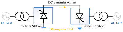 | |
|
| |
| Bipolar [64,65,66] | 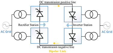 | |
|
| |
| Homopolar [65,66,67] | 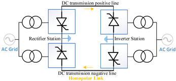 | |
|
| |
| Back-to-Back [66,67,68] | 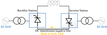 | |
|
| |
| Multi-terminal [66,69] | 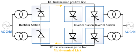 | |
|
| |
| Methods | Domain | Working Principle | Advantages and Limitations |
|---|---|---|---|
| Fourier Transform (FT) [85] | Frequency | Decomposes signal into sinusoidal components |
|
| Discrete Fourier Transform (DFT) [85,86] | |||
| Fast Fourier Transform (FFT) [85,86] | |||
| Empirical Mode Decomposition (EMD) [87,88] | Time | Decomposes signal into finite components (Intrinsic Mode Functions (IMFs)) |
|
| Intrinsic Time Decomposition (ITD) [89] | Decomposes signal into a trend (baseline) and details (Proper Rotating Components), including amplitude, frequency, and phase |
| |
| Mathematical Morphology (MM) [90,91] | Represents signal profiles in the time domain with a small sampling window |
| |
| Wavelet Transform (WT) [92,93] | Time–frequency | Both time and frequency resolution analysis of transient features and spectral content |
|
| Discrete Wavelet Transform (DWT) [94] | Discrete level of WT |
| |
| Continuous Wavelet Transform (CWT) [95] | Analyzes the signal at every possible scale |
| |
| Dual Tree Complex Wavelet Transform (DTWT) [95] | Improves DWT by using two parallel wavelet trees |
| |
| Maximum-Overlap Discrete Wavelet Transform (MODWT) [95,96] | A variant of DWT |
| |
| Lifting Wavelet Transform (LWT) [96] | An efficient and flexible approach to computing DWT |
| |
| Stockwell Transform (ST) [97,98] | A generalized extension of the WT, combining the simultaneous analysis in multidomains of wavelets with a frequency-dependent Gaussian window |
| |
| Short-Time Fourier Transform (STFT) [99,100] | Fixed-window FT over time |
| |
| Variational Mode Decomposition (VMD) [101,102,103] | Uses non-recursive methods to decompose signals into multiple Band Limited Intrinsic Mode Functions (BLIMFs)It constrains each mode to a narrow frequency, making it a time–frequency method |
| |
| Hilbert Huang Transform (HHT) [104,105] | EMD + Hilbert transform |
|
| Reference | Method | System | Domain | Input Data | Detection Time | Fault | Comments |
|---|---|---|---|---|---|---|---|
| [106] | DFT | Two-Terminal | Frequency | Voltage/ Current | <5 ms | PG, PP |
|
| [107] | DFT | Multi-Terminal VSC | Frequency | Voltage/Current | <5 ms | PG, PP |
|
| [108] | FFT | Four-Terminal VSC-HVDC | Frequency | Voltage/Current | 1–1.5 ms | PPG, NPG, PP |
|
| [109] | FFT | Four-Terminal | Frequency | Voltage | ~2.5 ms | PP, PG |
|
| [110] | STFT | Four-Terminal VSC-HVDC | Time–frequency | Voltage/Current | 0.5 ms | PG |
|
| [111] | STFT | Multi-Terminal (CIGRE B4 DCS2) | Time–frequency | Voltage/Current | <5 ms | PP, PG |
|
| [112] | WT | Four-Terminal VSC-HVDC | Time–frequency | Voltage/Current | 1.1 ms | PP, PG |
|
| [113] | WT | Four-Terminal | Time–frequency | Voltage/Current | <2 ms | PG |
|
| [114] | VMD | Four-Terminal VSC-HVDC | Time–frequency | Voltage/Current | Not mention | PP |
|
| [115] | VMD | Two-Terminal | Time–frequency | Voltage/Current | ~23 ms | PP, PG |
|
| [100] | ST | Multi-Terminal VSC-HVDC | Time–frequency | Current | 0.3 ms | PP, PG |
|
| [116] | ST | Two-terminal VSC-HVDC | Time–frequency | Current | - | - |
|
| [117] | MM | Multi-terminal VSC-HVDC | Time | Current | 0.15 ms | PP, PPG, NPG |
|
| [118] | MM | Four-terminal | Time | Voltage | 0.95 ms | PG, PP |
|
| [119] | ITD | Three-terminal VSC-HVDC | Time | Current | <0.8 ms | PPG, NPG, PP |
|
| [120] | HHT | Multi-terminal VSC-HVDC | Time–frequency | Current | <2 ms | PP, PG |
|
| [121] | HHT | Four-Terminal | Time–frequency | Voltage/ | <1 ms | PPG, NPG, PP |
|
| [87] | EMD | Four-terminal VSC-HVDC | Time | Current | 0.2 ms | PP, PG |
|
| [94] | DWT MODWT | Two-terminal VSC-HVDC | Time–frequency | Current | <1 ms | PP, PG |
|
| [122] | DWT MODWT | Two-terminal | Time–frequency | Current | PP, PG |
|
Disclaimer/Publisher’s Note: The statements, opinions and data contained in all publications are solely those of the individual author(s) and contributor(s) and not of MDPI and/or the editor(s). MDPI and/or the editor(s) disclaim responsibility for any injury to people or property resulting from any ideas, methods, instructions or products referred to in the content. |
© 2025 by the authors. Licensee MDPI, Basel, Switzerland. This article is an open access article distributed under the terms and conditions of the Creative Commons Attribution (CC BY) license (https://creativecommons.org/licenses/by/4.0/).
Share and Cite
Zafari, L.; Liu, Y.; Ukil, A.; Nair, N.-K.C. Advances in HVDC Systems: Aspects, Principles, and a Comprehensive Review of Signal Processing Techniques for Fault Detection. Energies 2025, 18, 3106. https://doi.org/10.3390/en18123106
Zafari L, Liu Y, Ukil A, Nair N-KC. Advances in HVDC Systems: Aspects, Principles, and a Comprehensive Review of Signal Processing Techniques for Fault Detection. Energies. 2025; 18(12):3106. https://doi.org/10.3390/en18123106
Chicago/Turabian StyleZafari, Leyla, Yuan Liu, Abhisek Ukil, and Nirmal-Kumar C. Nair. 2025. "Advances in HVDC Systems: Aspects, Principles, and a Comprehensive Review of Signal Processing Techniques for Fault Detection" Energies 18, no. 12: 3106. https://doi.org/10.3390/en18123106
APA StyleZafari, L., Liu, Y., Ukil, A., & Nair, N.-K. C. (2025). Advances in HVDC Systems: Aspects, Principles, and a Comprehensive Review of Signal Processing Techniques for Fault Detection. Energies, 18(12), 3106. https://doi.org/10.3390/en18123106