1. Introduction
Photovoltaic (PV) systems have gained widespread popularity due to its cleanliness, abundance, and eco-friendly nature compared to traditional energy sources [
1]. The global shift towards solar PV energy demands technological revolutions in power optimization via creative solutions that dynamically modify the operating conditions, ensuring the system constantly operates at its optimal power under dynamic environmental conditions [
2]. Maximizing the efficiency of PV systems through maximum power point tracking (MPPT) is thus critical. Recent advancements in artificial intelligence (AI) have shown remarkable potential to improve the MPPT performance [
3].
PV system’s performance and efficiency are mainly dependent on environmental factors such as solar irradiance, temperature, and especially the shading conditions [
4]. Partial shading is caused by factors like trees, buildings, and clouds, which result in less energy production and affect the overall performance of the PV system [
5]. Therefore, the optimization of PV system’s efficiency under partial shading conditions (PSCs) is crucial to enhance its reliability and has emerged as a critical area of research, with a particular emphasis on the global maximum power point tracking (GMPPT) [
6]. Under varying environmental conditions, the GMPPT algorithms continuously adjust the operating point to track the global maximum power point (GMPP) of the PV system [
7]. Thus, GMPPT is of importance to optimize the energy harvesting and to improve the PV system’s reliability towards a sustainable renewable energy future [
8].
Conventional techniques such as hill climbing, perturb and observe (P&O), and incremental conductance (INC) have been commonly utilized for the MPPT control [
9]. However, these methods face challenges in accurately tracking the GMPP with slow convergence or local maxima issues under changing weather patterns, resulting in less energy harvesting and decreased system performance [
10]. To overcome the limitations and drawbacks faced by conventional MPPT techniques, more complex and real-time adaptive tracking algorithms are required [
11].
Over the last years, AI has been widely adopted in PV systems with the growing focus on the sustainable energy and for the better utilization of renewable energy sources [
12]. AI has emerged as a powerful tool to improve the power generation and efficiency, by analyzing complex data, predicting real-time fluctuations, optimizing future energy generation patterns, and ultimately reducing costs and downtime [
13]. AI techniques like artificial neural network (ANN), fuzzy logic control (FLC), adaptive-neuro fuzzy inference system (ANFIS), machine learning (ML), particle swarm optimization (PSO), genetic algorithm (GA), and various hybrid approaches are increasingly popular being integrated into MPPT control strategies [
14]. Under non-ideal circumstances, AI-based MPPT techniques can optimize the output power of PV systems more accurately and efficiently compared to conventional techniques [
15]. Furthermore, AI algorithms learn from the past data, and track the GMPP in real-time under varying environmental conditions, which provides a sustainable solution in optimizing the PV power generation under PSCs, to achieve stability with faster tracking dynamics and higher efficiency around the GMPP [
16]. The selection of a high-resolution dataset to train the MPPT also plays a crucial role in improving the efficiency of PV systems [
17]. AI can help renewable energy systems including solar PV energy to enhance the energy harvesting and improve the performance with a cost-effective solution [
18].
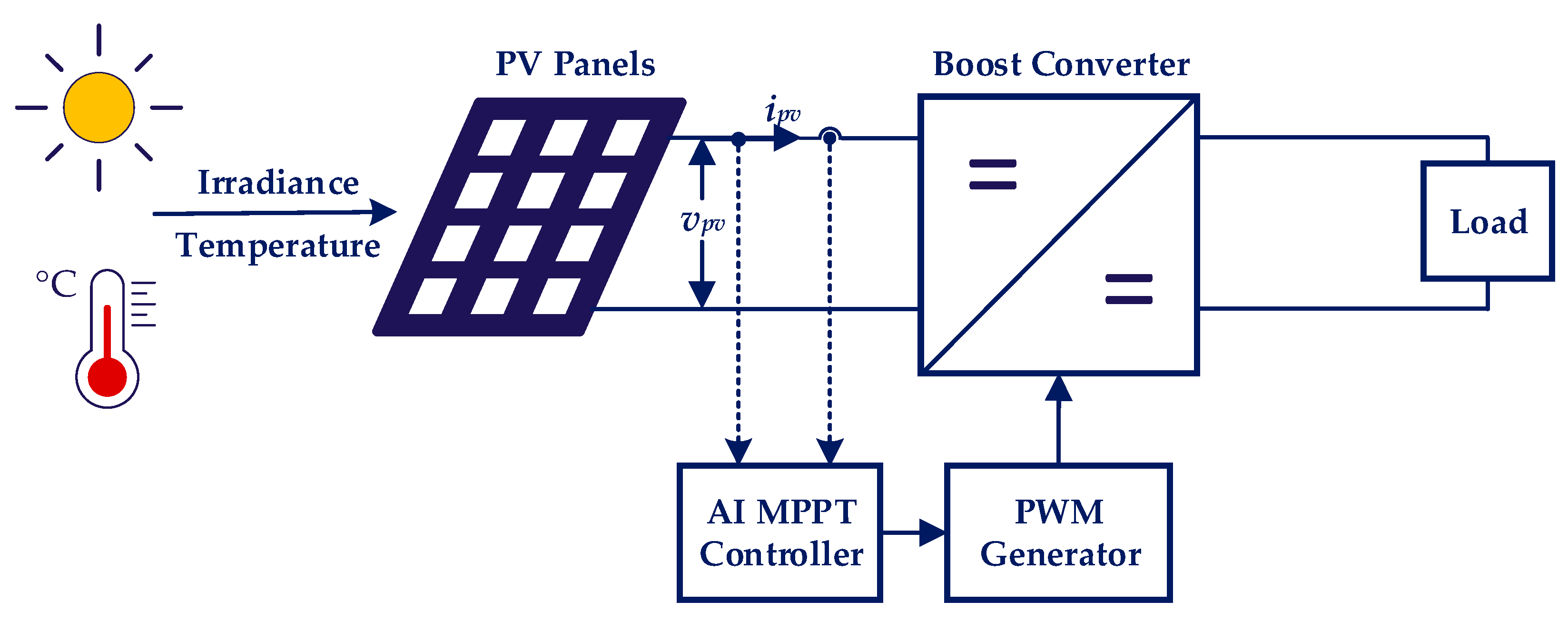
Figure 1 shows the basic structure of a PV system with the implementation of the AI-trained MPPT controller.
AI and metaheuristic optimization methods are widely applied to improve the PV system control, especially for the MPPT control under PSCs [
19,
20]. Advanced ANN techniques are integrated with metaheuristic algorithms like the PSO, grey wolf optimization (GWO), and harris hawks optimization (HHO) to better tune the ANN weights and improves the convergence speed and reduce the oscillations [
21,
22,
23]. In addition, hybrid AI techniques combines the FLC with swarm algorithms like multi-verse optimization and memetic PSO techniques to improve the adaptability under varying irradiance, tilt angle and temperature conditions [
24,
25,
26]. Moreover, further publications have shown that hybrid and bio-inspired algorithms like rat swarm optimizer and satin bowerbird algorithm outperform conventional methods with faster tracking dynamics and minimal oscillations [
27,
28]. Recent studies highlight that AI techniques play a key role in reducing hardware malfunctions like predictive maintenance, anomaly detection, and real-time diagnostics. AI improves the reliability, efficiency, and reduces disruptions by continuously monitoring systems and detecting early signs of failure [
29]. Despite of advantages, these advanced techniques have several limitations like dependency on offline parameter tuning and premature convergence under highly dynamic conditions, making them less adaptive to dynamic changes in real-time [
30,
31]. These hybrid models heavily increase the computational complexity, enhancing the implementation costs and demand for special hardware [
32].
The selection of AI-based control strategies, to analyze and compare various factors including the implementation complexity, practical applications, costs, dynamics, and precision in steady-state conditions is a mission difficult. In this paper, a comprehensive comparative analysis is thus presented on AI-based techniques for effectively tracking the GMPP. The paper focuses on reviewing famous AI techniques and optimizing them to track the GMPP, which will help future researchers in designing more effective and improved GMPPT algorithms customized to their system requirements and capable of adapting to changing weather conditions. More importantly, a modified PSO algorithm is proposed, advancing the GMPPT control in PV systems. The modified PSO algorithm dynamically updates the particle particle’s weight and acceleration coefficients in each iteration. Moreover, the modified PSO algorithm eliminates the effect of random variable compared to the traditional PSO, ensuring faster convergence and improved efficiency. The proposed PSO-based algorithms improve the adaptability, reduces tracking time, ensures robust performance, and maintains low computational burden under varying environmental conditions. All the AI techniques are experimentally benchmarked on a hardware-in-loop (HiL) platform during different shading patterns, which proves that the modified PSO offers optimized output power, faster dynamics, and enhanced stability of the PV system under PSCs.
The rest of the paper is structured as follows:
Section 2 describes how partial shading affects the performance and output characteristics of the PV system.
Section 3 delves into the practical application of the selected AI techniques, focusing on their integration to track the GMPP, where a modified PSO-based GMPPT method is proposed. In
Section 4, a comparative analysis is conducted, highlighting the influence of the selected AI techniques on the power generation, tracking speed, efficiency, and the performance of the PV system with the experimental results obtained from a HiL platform. Furthermore, a detailed analysis considering the advantages and disadvantages of the selected AI techniques is conducted. Finally,
Section 5 concludes the paper.
2. Impact of Partial Shading on PV Characteristics
Under PSCs, the PV power generation is no longer restricted to open area installations, where the irradiance is obstructed, and the PV modules/panels receive uneven distribution of irradiance on the surface [
33]. The non-uniform irradiance can be caused by various factors like shading produced by trees, buildings, bird dropping, nearby objects, and clouds [
34]. Under non-uniform irradiance conditions, the characteristics of the PV cells are changed, and the shaded cells produce less energy and reduce the overall efficiency of the entire PV system [
35].
When there is shading on one panel in a PV string, it acts as a load rather than generating power, as shown in
Figure 2a. Therefore, the shaded panel starts dissipating power generated by other panels in the string which shows a sharp drop in the output current of the PV system. This leads to a huge power loss and affects the overall performance and efficiency of the PV system. To mitigate this issue, a bypass diode can be connected across each panel, as seen in
Figure 2b. Under shading conditions, the bypass diode provides an alternative path to the current flowing from other PV panels in the string, and the PV string no longer remains in the power dissipation range [
36]. The PV panels that are not obstructed by the light increase the power generation effectively, by solving the heat generation and power loss problem [
37].
The current–voltage (I–V) and power–voltage (P–V) curves of a PV string for uniform and non-uniform irradiance are exemplified in
Figure 3. There are multiple peaks, and the maximum power among all the peaks is called GMPP [
38]. An MPPT controller needs to continuously adjust the operation point of the PV panel at GMPP under different environmental and shading conditions, to improve the energy harvesting and efficiency of the PV system [
39].
Bypass diode avoids hot spot to some extent. It is the most common way to optimize the power generation during PSCs, but it cannot fully optimize the power generation by itself [
40]. A suitable MPPT controller is needed to control the PV inverter and to achieve the optimum power tracking [
41]. AI-based GMPPT algorithm has not been commercialized despite its huge potential to mitigate the power mismatch issue [
42]. A detailed review on the AI-based GMPPT algorithms needs to be carried out to provide focus on its great potential in optimizing the power generation, especially under PSCs [
43].
3. Artificial Intelligence Based GMPPT Techniques
3.1. Fuzzy Logic Control (FLC)
A fuzzy control strategy is used to continuously adjust the step size to solve the problem of large fluctuations at the MPP that arises when utilizing conventional techniques like INC and P&O with a fixed step size [
44]. The FLC is a logic-based control system that works on the digital values, 0 and 1 [
45]. The fuzzy controller considers the variations in voltage and power as input variables, i.e., Δ
P and Δ
V, for making precise adjustments during the optimization and the output variable is the change in the input of the PWM generator, duty cycle, i.e., Δ
D [
46]. The current input power and voltages are compared with their delayed values, to determine the error signal and its change as
where
P is the input power,
V is the input voltage of the PV system,
E is the error signal, and Δ
E is the change of the error signal with k being the current time step. The FLC consists of three main parts: fuzzification, inference and defuzzification [
47]. It can easily track and adjust its membership functions and rules in response to changes in the PV system’s behavior due to its adaptive nature. This dynamic behavior demonstrates the vital flexibility of the FLC, which is essential for efficiently maximizing the GMPPT performance. The fuzzy subsets of Δ
P and Δ
V are defined as
with the fuzzy subsets of Δ
D being given as
Here, the fuzzy concepts: negative large, negative medium, negative small, zero, positive small, positive medium and positive big are represented as NB, NM, NS, ZE, PS, PM, PB. The three fuzzy domains are set in the range of [−1, 1]. The membership functions of three fuzzy domains use a uniformly distributed triangular function and its mesh plot is shown in
Figure 4,
Figure 5 and
Figure 6.
The fuzzy rule works on the same control strategy as INC by determining the next control quantity based on the variations in power and voltage [
48]. When the control quantity is far away from the MPP, a larger step size is used and when it is near the MPP, the step size should be adjusted to a smaller value [
49].
The fuzzy control rules to track the GMPP are shown in
Table 1.
Figure 7 shows the FLC flowchart to track the GMPP under PSCs. By using (1) and (2),
E(
k) and Δ
E(
k) are calculated from the variation of voltage and power of the PV system.
The conventional FLC algorithm has been optimized, and a hybrid GMPPT algorithm is designed for the PV system to track the GMPP under PSCs, as presented in the flowchart shown in
Figure 7. This technique enables the conventional FLC algorithm to perform a global search and monitors the stability of the system to optimize the power extraction. Initially, the PV system’s voltage, current, and power are calculated for the current time step. Subsequently, the algorithm determines the presence of partial shading by examining variations in power and voltage across consecutive time steps. When partial shading is detected, a global search algorithm is activated. During this global search, the duty cycle range is scanned, and multiple iterations are carried out to identify the GMPP. This process continues until the maximum power (
Pmax) is achieved. Once the optimal duty cycle (
dmax) is obtained, the control parameters are updated to enable continuous tracking of the GMPP.
If PSCs are not detected, the algorithm proceeds to calculate the change in power. However, if PSCs are encountered, the global search scan is activated before the calculation of the change in power. After that, if the magnitude of the power change needs adjustment, the FLC is activated. The FLC is based on three steps: Firstly, fuzzification selects membership functions (MFs) to convert the numerical values of
E(
k) and Δ
E(
k) into linguistic sets. Secondly, a rule-base system is used to control the inference system’s output and design fuzzy rules using various input-output combinations, as shown in
Table 1. In the last stage, to activate the boost converter and obtain the MPP, defuzzification transforms this controller’s output into an analog signal in the form of duty cycle (
d). Additionally, a recovery factor is built into the control mechanism to modify the perturbation step as needed. The method may more effectively react to shifting operating conditions by modifying the perturbation step, which will guarantee more stable and effective PV system functioning.
Furthermore, a stability control mechanism monitors the consistency of the MPP. For multiple consecutive iterations, if ∆P is lower than a threshold, the stability counter is incremented. Once the stability counter surpasses a specified limit, the value of d is stabilized. This stabilization is crucial as it prevents unnecessary oscillations around the MPP, which could otherwise lead to power losses and reduced system efficiency. Finally, the value of d is updated. The algorithm then continues to iterate, making power adjustments based on the outcomes of either the global search or the fuzzy logic control. This iterative process ensures that the GMPPT operation remains optimal and stable for PV systems, even when operating under dynamic environmental conditions or partial shading.
3.2. Artificial Neutral Network (ANN)
The ANN is an intelligent technique that is inspired by the human brain’s understanding to make precise output predictions, created by mathematical and physical methods and information processing for complicated and substantial datasets [
50]. The ANN is simply a mathematical model that can be simulated by a computer program and making it an important AI technique to track the maximum power even under varying environmental conditions [
51]. It is an effective tool that learns from the experimental input data of the PV system [
52]. An ANN is composed of interconnected layers, called “neurons” that process the information [
53]. An ANN consists of an input layer, a hidden layer, and an output layer to intelligently calculate the complex connection between the neurons that are the building blocks of the ANN, as shown in
Figure 8.
The ANN accepts one or more inputs, adds them up, and then, uses an activation function to generate the output.
Figure 9 shows the architecture of the ANN. During this process, the hidden layer uses a nonlinear sigmoid activation function. The input and desired target output data are imported to the ANN training model. The layer size will be selected according to the complexity of the data [
54]. By providing temperature and irradiance datasets, an ANN calculates the desired factors like the maximum power, maximum voltage etc.
There is not any specific method for the selection of the number of neurons in the hidden layer. Here, the selection of neurons is made according to:
where
a is the number of neurons in the input layer,
b is the number of neurons in the output layer,
q is the number of neurons in the hidden layer, and
n is a constant range from 1 to 10.
The flowchart for tracking the GMPP in the PV systems using a combination of adaptive global search and ANN strategy is shown in
Figure 10. Initially, the voltage (
vpv) and current (
ipv) values are measured from the PV system, which are used to calculate the power output. The flowchart checks whether there is a change in the shading pattern or not. If a change in the shading pattern is detected, the system moves towards the ANN training mode to adapt to the PSCs. Conversely, if no change in the shading pattern is observed, the algorithm uses the previous best voltage as the predicted GMPP voltage (
Vref) from the ANN and directly progresses to the adaptive global search process until the shading pattern changes.
The ANN control strategy is used to establish a relationship between the voltage and power output of the system. The ANN is trained using a dataset composed of the measured voltage and current or irradiance and temperature values. ANN training is performed in three stages: training, testing, and validation. Generally, 70% of experimental data is selected for training, 15% for testing and 15% for validation. In the first step, the weights and biases within the network are randomly initialized. Generally, the selection of a training technique depends on the nature of the training dataset. There are techniques to train datasets of irradiance and temperature which are fed to PV systems. Among them, the Levenberg-Marquardt technique provides fast convergence for computationally stable problems. Bayesian regularization technique avoids overfitting and handles noisy data well. The scaled conjugate gradient technique is efficient for large-scale and complex data because of its capability to reduce computational burdens. Subsequently, the weights and biases are updated to minimize the error if the mean squared error (MSE) is more than its threshold value. After the training is completed, the performance of the model is evaluated. At this point, the output layer, which has a linear activation function, receives the result which is produced by the hidden layer. The validation process of the network produces suitable parameters for the learning algorithm and modifies the combinations through a series of iterations.
The prediction accuracy is evaluated by
MSE, which is measured by:
where
is the desired target value and
is the output value of the network. Six variables of irradiance and temperature for three PV panels are given as the input, whereas the voltage is selected as an output to train the ANN model under PSCs. Optimizing the number of neurons and percentage of data in three stage increases the network efficiency. The ANN architecture performs best when the
MSE is low and coefficient of determination (R-squared) is high, which indicates the fit integrity of experimental data as
Specifically, if the MSE is lower than the threshold, Vref predicted by the network is taken as the optimal voltage for tracking the GMPP.
During the adaptive global search, the system conducts a scan within a predefined voltage range predicted by the ANN. For every voltage value within this range, the system computes the corresponding power (Pi). When the calculated power Pi exceeds the previously recorded maximum power (Pprev), both the power and the associated voltage (Vprev) values are updated. Upon the completion of the adaptive global search, the system proceeds to the fine-tuning phase of the voltage. In this phase, a relatively narrow voltage range of Vref ± 5 V is explored with voltage increments set at 0.05 V. If a new voltage within this range results in a more optimal power output, the values of the optimal voltage and power are updated.
The outcome from this process is the most optimal voltage (best voltage) that maximizes the output power of the PV system, which is crucial for efficient energy harvesting. This approach combines both the adaptive global search for broad optimization and ANN-based fine-tuning for precise tracking, ensuring that the system can adapt to varying conditions and achieve optimal performance.
3.3. Adaptive Neuro-Fuzzy Inference System (ANFIS)
The ANFIS is a technique that integrates the characteristics of the FLC and ANN and establishes input-output mapping using intelligent algorithms. It combines the benefits of the FLC and ANN [
55]. An FLC-based MPPT is driven by an ANN that is trained to estimate the ideal GMPP [
47]. Fuzzy logics and ANFIS are ideal, versatile, and able to be adjusted to any new setup for PV systems and smart power management [
56]. Fuzzy logics are modeled using the neuro-adaptive learning technique, to learn all the information about a dataset. This method involves the mapping of entire datasets from several inputs into a single input [
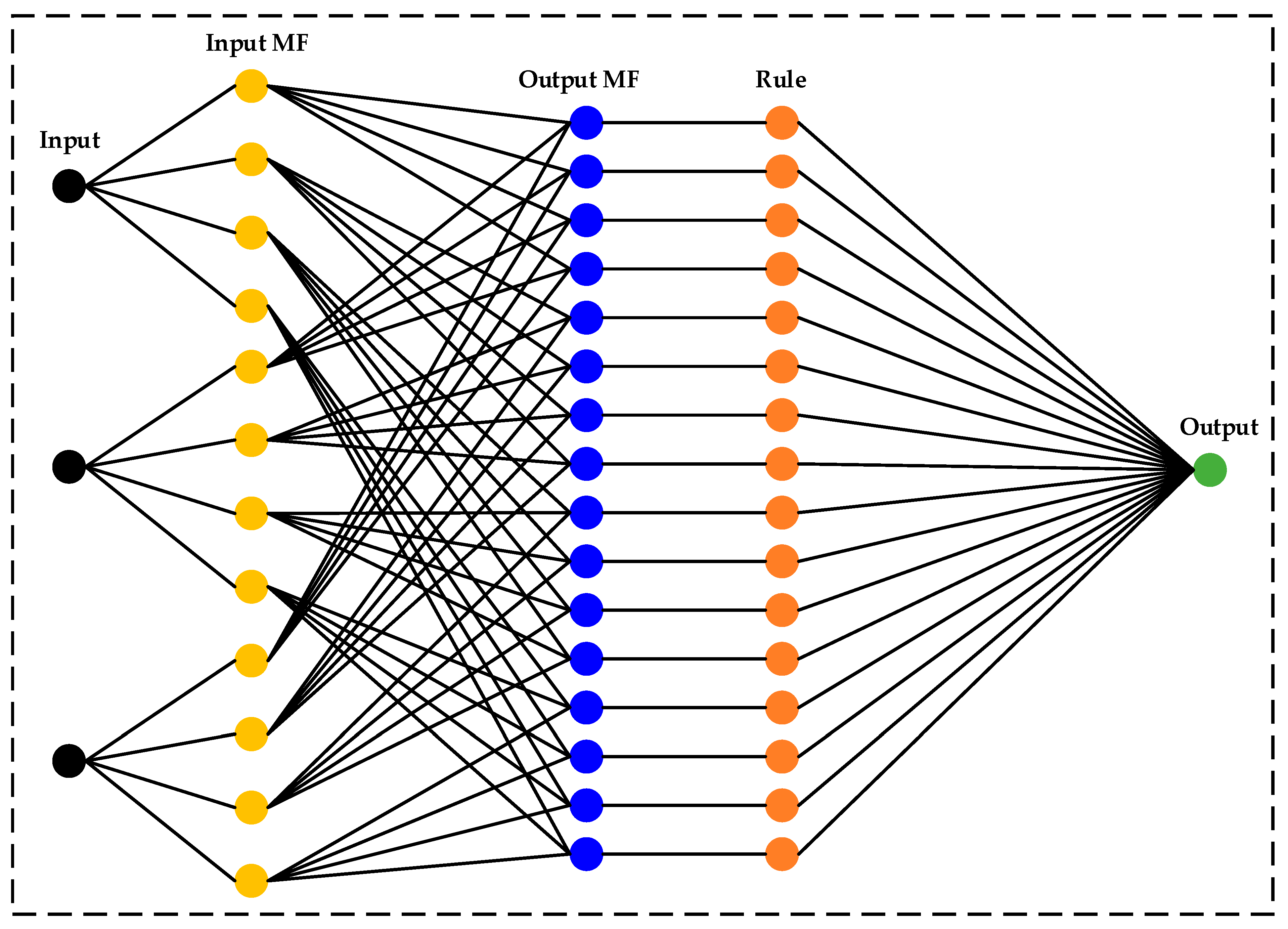
57]. The basic model structure explaining the working process of the ANFIS from the input to the output is shown in
Figure 11. The ANFIS technique is based on three key concepts [
58]:
A rule designer that is based on the fuzzy rules;
A database uses fuzzy rules to identify membership functions;
An optimization method that trains the rules to derive an output.
The flowchart, shown in
Figure 12, presents a comprehensive hybrid algorithm for tracking and optimizing the GMPP of a PV system under PSCs, using an ANFIS control strategy. The algorithm starts with the collection of input data, including irradiance (
G), temperature (
T), current (
ipv) and voltage (
vpv). Subsequently, the system computes the difference in power (
dP) and voltage (
dV), which serve as crucial parameters for detecting PSCs. Once partial shading is detected, the process advances to the global search. During global search, voltage bounds are precisely defined, and an adaptive step size (Δ
V) is calculated. The voltage is then scanned incrementally. Based on whether the power is increasing or decreasing, the voltage is adjusted. This iterative process continues until the voltage scan is fully completed, which is indicated by setting the flag (Flag = 0) and finalizing the reference voltage (
Vref) such that
Vmax =
V. This systematic approach ensures efficient operation of the PV system, maximizing power extraction even under complex partial shading scenarios.
If partial shading is not detected, the process proceeds directly to the ANFIS control loop. The model’s inputs can be vpv and ipv or G and T, and the output parameter can be Pmax or Vmax, based on the designed requirements. In this loop, the collected input datasets are divided and used for training (70%) and testing (30%), separately. This data division is crucial for the development and validation of the model. The system then undertakes the generation of the fuzzy inference system (FIS). This involves carefully selecting key clustering parameters, such as the number of MFs and the types of both input and output MFs. These parameters play a fundamental role in shaping the behavior and accuracy of the FIS. To determine the exact MFs for each input variable, the ANN trains the Sugeno fuzzy controller. Triangular MFs (trimF) are used due to their dynamic variation handling in quick processing time. A comprehensive rule base can also be created by deriving the weights of the nodes involved. The rule table and MFs can be adjusted with the help of the ANN after being tested on the test data. For the optimization of nonlinear functions, the ANFIS controller’s inference system corresponds to a collection of fuzzy rules with learning fitness. If root mean square error (RMSE) is less than a predefined threshold, the predicted Vref is exported as the optimal value for the PV system. The process ends with the output of the optimal voltage reference (Vref), ensuring maximum power extraction from the PV system under the given conditions.
The integration of ANFIS with the global search algorithm thus ensures the maximum power extraction and enables the system to better capture complex nonlinear relationships, resulting in improved tracking accuracy and robustness under PSCs [
59]. Similarly, the hybridization of ANFIS with other AI techniques improves the efficiency and performance of PV systems, particularly to achieve the GMPPT [
60]. In several papers, techniques like PSO and ML have been combined with ANFIS to optimize system parameters and improve model adaptability under dynamic conditions [
61]. Optimization methods like ant colony optimization and GA further strengthen ANFIS performance by ensuring convergence toward global optimal solutions [
62].
3.4. Particle Swarm Optimization (PSO)
The PSO is a metaheuristic method that is inspired by the movement and coordination of organisms, e.g., fish schooling behavior and a flock of birds, to achieve the optimal solution [
63].
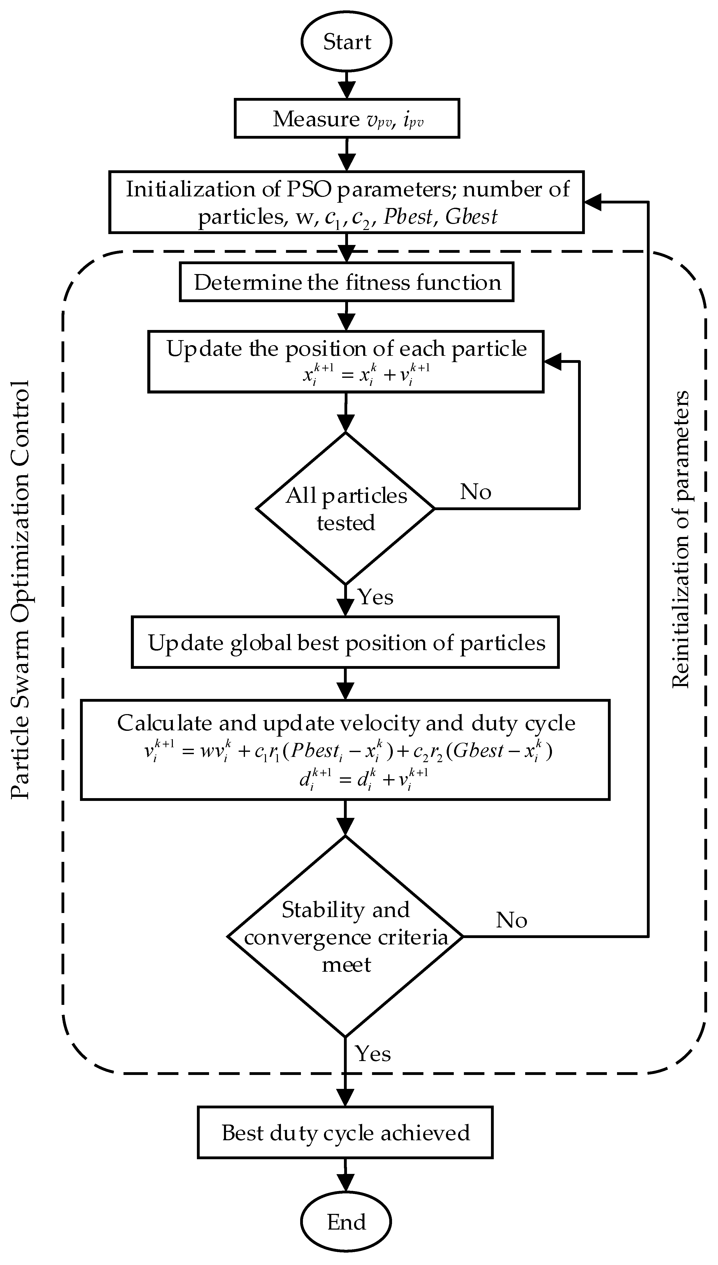
Figure 13 presents the algorithm of the conventional PSO to track the GMPPT. A particle’s position indicates the possible solution [
64]. To find the best optimal solution, several particles move through the search space [
65]. The particle’s position is continuously modified by experimenting with different solutions, to find the best optimal solution [
66].
The particle’s position is compared with the personal best position, and then, the global best position during each iteration. The particle’s position and velocity are updated according to the following:
where
x is the particle’s position,
v is the particle’s velocity,
w is the inertia weight,
and
are random variables,
and
are the acceleration constants,
represents the personal best position of the particle in each iteration and
represents the global best position of the particle. The particle’s position defines the duty cycle
values used to trigger the boost converter while tracking the GMPPT of the PV system. Therefore, we can update (9) and (10) as:
in which
k is an index that represents the current position of each particle.
There are certain challenges that the conventional PSO algorithm needs to overcome, such as difficulty in designing of parameters, high computational burdens, occasionally low search efficiency and significant oscillations. The PSO algorithm’s tracking efficiency is greatly influenced by its learning elements and weighting value [
67]. Additionally, random variables also affect the overall tracking speed. It is impossible to identify a global optimal solution from a multiple-peak curve if the weighting value is either too low or too high. Similarly, an extremely high acceleration coefficient is not acceptable. An optimized PSO algorithm is required to improve the PSO algorithm, which results in the improvement of dynamics and enhances the reliability and efficiency of the PV system.
3.5. Modified PSO Algorithm
A modified PSO algorithm is thus proposed, which involves the removal of random variables and instead of using constant values for weight and acceleration coefficients. Modified formulas are implemented to continuously adjust the learning parameters to improve the dynamics and efficiency of the PV system. The flowchart of the modified PSO algorithm to improve the tracking accuracy, and dynamics of the PV system is shown in
Figure 14. Random coefficients provide metaheuristic algorithms with more possibilities to explore. However, as the GMPP is crucial for energy harvesting, it is best to eliminate the possibility of missing the GMPPT by removing random variables. As the conventional PSO algorithm involves random variables to update the particle’s position, as shown in (10), which may fail to attain the GMPP occasionally. To resolve this issue, random variables are removed as in (13). The cancellation of random variables clearly eliminates the unpredictability of iterations and reduces the computation burden.
Moreover, the constant weight value has a great impact on the dynamics of the PV system. If the weight value is low, it results in an inadequate particle movement distance. On the other hand, an extremely high weighting value, results in a large particle movement distance and is therefore unable to correctly track the GMPPT. Therefore, the weight value is adjusted according to the iteration number as
where
w is the weight,
and
are the initial and final weight values,
is the maximum number of iterations, and
n is the current iteration of each particle. This weight modification strategy provides a balance between exploration and extraction, by reducing the inertia weight as it progresses towards the GMPP.
Furthermore, acceleration coefficients affect the speed to track the GMPPT. If the value of the acceleration coefficients is too high, it will decrease the overall tracking efficiency of the PV system. Therefore, a dynamic coefficient adjustment is required to enhance the performance of the tracking algorithm as
where
and
are the initial and final values of acceleration coefficients,
n is the current iteration, and
is the maximum number of iterations of the particle. This optimized strategy adjusts the acceleration coefficient in a smooth and controlled way towards the tracking of the GMPP.
Although (14) and (15) cannot achieve the GMPPT on their own, they are essential in figuring out how particles behave in the search space. For more simplified structure of the modified PSO algorithm, the design parameters of (17) can be reduced, which leads to lower the computational burden:
The modified PSO algorithm resolves all the uncertainties of the conventional PSO algorithm. It improves the dynamics and efficiency of the PV system by simplifying the structure of the PSO algorithm, removing unnecessary coefficients, and modifying the weight and acceleration coefficients in real-time according to the current iteration. This algorithm not only improves the efficiency, but also reduces the computational burden and enhances the reliability of the PV system.
4. Experimental Benchmarking of the Selected AI Techniques
The evaluation and comparison of different AI techniques to determine the performance of the PV system, such as efficiency, tracking speed, complexity, and sensitivity to track the GMPP under PSCs, are important. In this section, experimental validation of different AI techniques, such as the FLC, ANN, ANFIS, PSO, and modified PSO, to track the GMPP under varying environmental conditions is conducted. Moreover, the advantages and disadvantages of each AI technique should be taken into consideration to understand the tradeoff and select the best AI-based GMPPT technique. The parameters of the PV array are listed in
Table 2.
For the effective implementation of the GMPPT in the PV systems by using AI, a high-resolution dataset is necessary. The high-resolution sunny day dataset produces faster and more accurate results than the low-resolution dataset [
17]. Various AI techniques are trained on a continuous 24-h dataset obtained from the National Renewable Energy Laboratory (NREL) [
68].
Figure 15a,b shows the solar irradiances and the ambient temperature profiles, respectively, that were used, used to train the selected AI techniques for tracking the GMPP of the PV system.
4.1. Experimental Setup
The experimental setup for the system validation is composed of multiple components, as shown in
Figure 16. The main component is the PLECS RT Box 2, which is used to implement the real-time simulation of the plant model. The RT Box 2 is connected to the host through a network cable and controlled by an external LaunchPad (LaunchXL—F28069M), a microcontroller responsible for managing and executing the control algorithms of the system with a DSP chip through analog and digital ports. After some pre-set software and hardware configurations, HiL experimental tests are performed, and the effectiveness of the selected AI-based GMPPT controllers is evaluated under PSCs.
4.2. Experimental Results
In this section, the GMPPT performance of the selected AI techniques such as the FLC, ANN, ANFIS, PSO, and modified PSO experimentally validated and discussed.
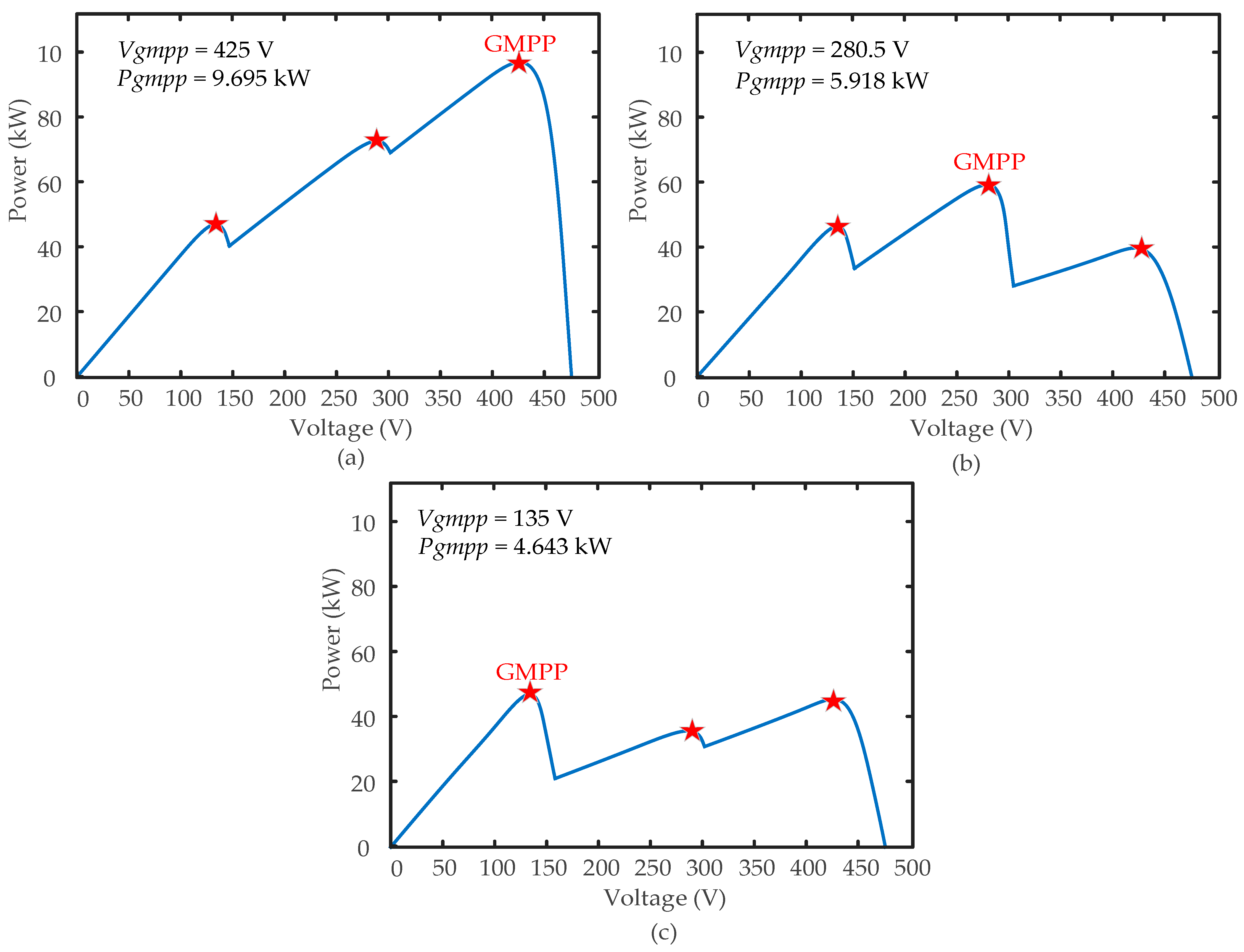
Figure 17 illustrates the theoretical voltage (
Vgmpp) and output power (
Pgmpp) of a PV string consisting of three peaks and three distinct shading patterns, listed as:
Case I: 1000 W/m2, 750 W/m2, 650 W/m2;
Case II: 1000 W/m2, 600 W/m2, 260 W/m2;
Case III: 1000 W/m2, 360 W/m2, 300 W/m2.
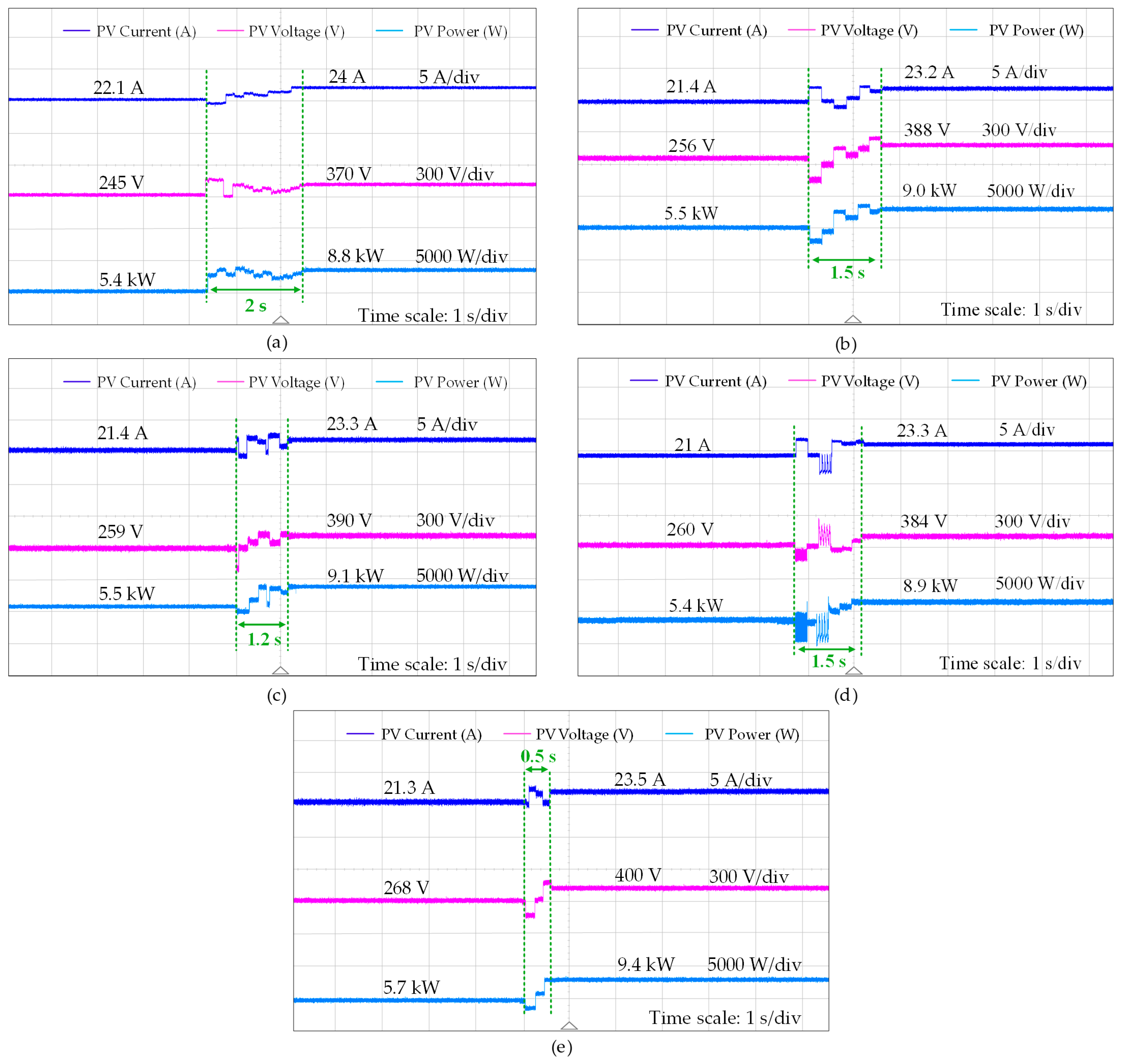
Figure 18 shows the GMPP tracking performance of the five AI techniques under dynamic weather conditions (from Case II to Case I). The tracking time to achieve the GMPP is a crucial performance metric. It is observed in
Figure 18 that when there is an abrupt change in irradiance, the FLC tracks the lower output power than other selected AI-based GMPPT techniques, and requires a tracking time of approximately 2 s. The ANN generates higher output power than the conventional PSO with a tracking time of 1.5 s. However, the tracking time for the conventional PSO is not consistent. Due to random variables, it fluctuates within the range of 1.5 to 2 s. The efficiency of the hybrid techniques such as ANFIS is significantly better than the ANN, FLC and conventional PSO. The ANFIS reduces the tracking time to 1.2 s and demonstrates a highly stable output.
The modified PSO algorithm is designed according to (13) to (16) by eliminating the effect of random variables, updating particle weight and acceleration coefficients which improves the tracking speed to achieve the GMPP during the varying weather condition. The algorithm is designed to quickly scan the entire PV curve after the change in shading pattern. The modified PSO algorithm outperforms all the other AI techniques, as shown in
Figure 18. It reaches the new GMPP in just 0.5 s, extracts the highest steady-state power (about 9.4 kW), and shows almost no residual oscillations. In conclusion, the modified PSO attains the overall balance and yields the most optimal results in terms of higher efficiency and faster dynamics, being highly reliable under dynamic shading conditions.
Figure 19 illustrates the voltage, current, and power output of the PV system under three distinct shading patterns (Case III to I) with the implementation of the modified PSO algorithm. In Case III, the PV system initially generates a maximum power of 4.4 kW before experiencing a sudden change in the shading pattern. The modified PSO algorithm successfully tracks the new GMPP of 5.7 kW within 0.5 s. A similar response is observed when transitioning from Case II to Case I, where the reduction in shading intensity results in a further power increase to 9.4 kW. Notably, the modified PSO algorithm consistently achieves faster dynamics (within 0.5 s) and superior power extraction across all cases, outperforming other AI-based GMPPT techniques in both tracking speed and efficiency.
4.3. Comparative Analysis
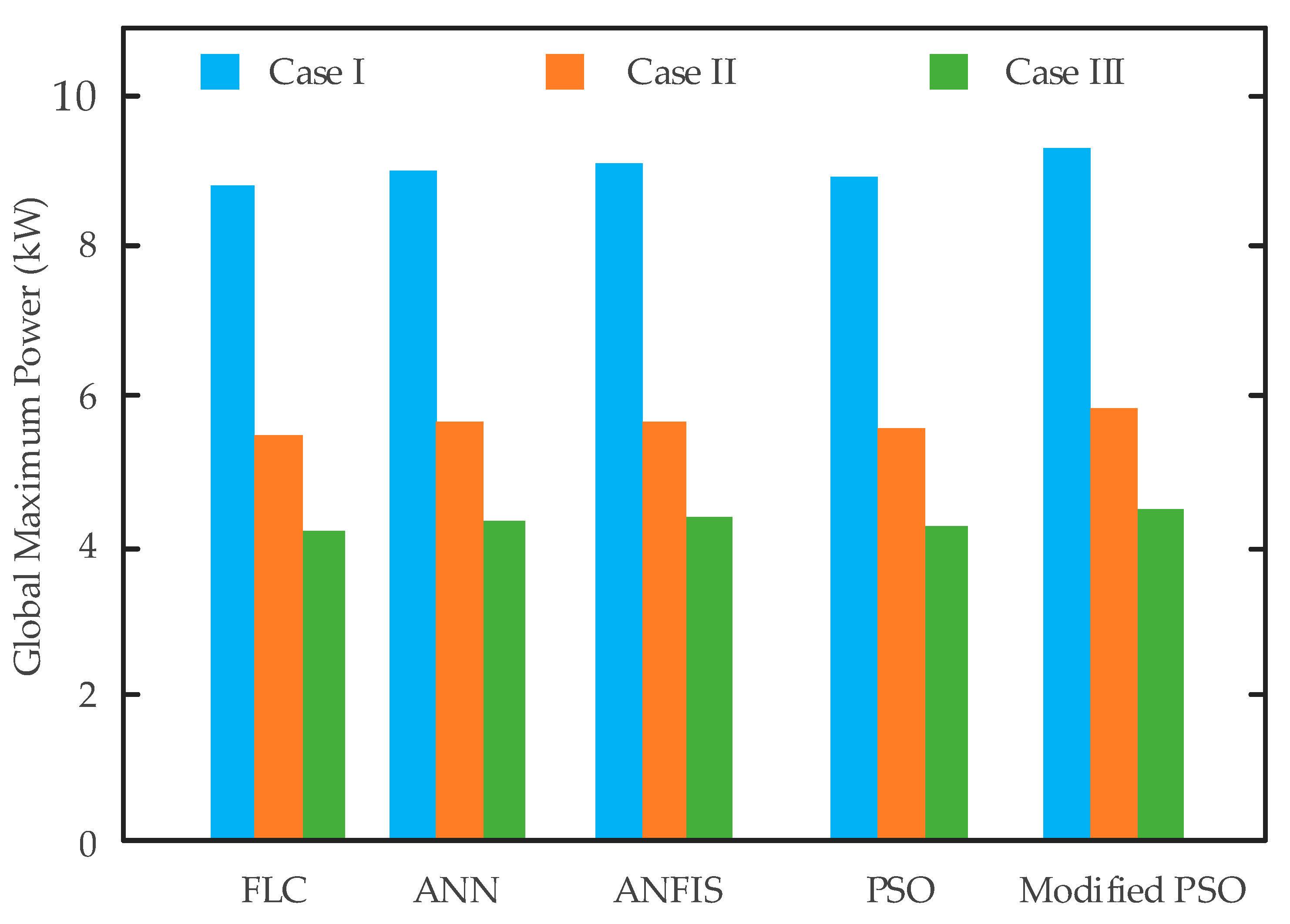
The GMPP achieved by all the five AI techniques (FLC, ANN, ANFIS, conventional PSO, modified PSO) under three dynamic shading patterns (Case I to Case III) is compared in
Figure 20. In lightly shaded Case I, all techniques extract power with values ranging approximately from 8.8 to 9.4 kW. Among them, the modified PSO shows the best performance, reaching around 9.4 kW, while the FLC shows the lowest performance, close to 8.8 kW. As the shading intensity increases in Case II, the harvested power drops to approximately 5.4 to 5.7 kW. Once again, the modified PSO leads with approximately 5.7 kW, and the FLC is at the lower end with around 5.4 kW. During the most severe shading conditions of Case III, the performance of all algorithms further deteriorates to about 4.1 to 4.4 kW. The ranking remains consistent with the modified PSO outperforming in terms of higher power extraction (about 4.4 kW), faster tracking speed, and improved system’s reliability under varying environmental conditions. Overall, across all shading patterns, the modified PSO approach consistently tracks closer to the actual global maximum power. In contrast, the FLC method shows the largest deviation, especially under non-uniform irradiance conditions.
However, when choosing an MPPT controller for hardware implementation, balance between the performance against the complexity and sensitivity to external factors is crucial. A comprehensive quantitative analysis of the selected AI-based GMPPT techniques in terms of tracking time, efficiency, computational complexity, and robustness is shown in
Table 3. As observed in
Table 3, the modified PSO algorithms shows superior performance, with the fastest tracking speed and the highest efficiency among all the selected AI techniques. The modified PSO algorithm significantly improves the robustness of the system by removing randomness and improving convergence behavior compared to the conventional PSO algorithm which shows lower robustness due to random variables and tendency to get trapped in local optima. Moreover, it is further observed that the ANN and ANFIS methods exhibit high efficiency with an increased computational burden.
The tradeoff between the advantages and disadvantages of each AI technique should be taken into consideration for the selection of the best suitable AI technique used to the track the GMPP of the PV system. A detailed comparison between the advantages and disadvantages of the AI-based GMPPT techniques is presented in
Table 4. The FLC is sensitive towards PSCs and can struggle under complex and non-linear systems without extensive rule tuning. The ANN can handle nonlinear input–output (I–V) relationships, and yet their accuracy heavily depends on the quality and training of the datasets. The ANFIS inherits the modeling flexibility of the ANN and the interpretability of the FLC and improves the system’s efficiency by adding extra computational burdens. Moreover, the modified PSO offers the best combination of robustness, convergence speed, and more adaptive versatility towards the GMPPT under PSCs with the slightly increased controller complexity. These findings highlight the value of the proposed technique in real-world applications, where speed and adaptability are critical parameters to enhance the energy harvesting. However, to find the most suitable AI technique according to the system design, the comparison analysis between the advantages and disadvantages of various AI techniques should also be taken into consideration.
Nevertheless, the modified PSO algorithm shows balanced system efficiency and computational complexity, leading to a strong potential for real-world applications. The ANN and ANFIS require a lot of memory resources and processing power, while the proposed modified PSO-based method does not need special hardware and can be easily implemented with commonly available microcontroller, which makes it suitable for real-world PV applications. Furthermore, the proposed algorithm can adapt to different PV system sizes. The proposed algorithm includes some fixed parameters like initial and final values of weights and acceleration coefficients, but its main operation relies on the feedback rather than large training datasets or specific system settings. Therefore, the proposed algorithm can be scaled up from small residential installations to large-scale installations with minor additional tuning of parameters, which ensures the reliability of the modified PSO algorithm to track the GMPP under various real-world environments.
5. Conclusions
This paper reviews famous AI-based MPPT techniques and optimizes them to track the GMPP. More importantly, a modified PSO algorithm is proposed which updates particle weight and acceleration coefficient in each iteration while eliminating the random variables as it approaches the GMPP. The modified algorithm quickly scans the entire PV curve after the abrupt change in shading pattern, ensuring a fast convergence speed. Meanwhile, the enhancement in efficiency over the traditional PSO algorithm is guaranteed. The effectiveness of the proposed method is validated under three distinct shading patterns. Additionally, the modified GMPPT algorithm is compared with the selected AI algorithms including the FLC, ANN, ANFIS, and conventional PSO, in terms of efficiency, dynamics, and reliability, under three shading patterns. Moreover, the advantages and disadvantages of various AI techniques are further summarized, enabling researchers to identify the tradeoffs and choose the most suitable solution according to the system’s design and application. In future work, application of the proposed technique across different converter topologies (e.g., boost, buck, and buck-boost) enhances its effectiveness and scalability in practical applications. In addition, to improve our understanding of AI techniques and enhance their feasibility and effectiveness, it is recommended that subsequent research include economic evaluations to analyze the feasibility and cost-effectiveness of AI techniques, and their ability to predict smart maintenance strategies compared to traditional techniques.


