Article

Model Reference Adaptive Sensorless Control of Variable-Speed Pumped Storage Doubly Fed Induction Machine Under Reversible Operations

1
Construction and Management Branch of China Southern Power Grid Energy Storage Co., Ltd., Guangzhou 511400, China
2
NR Electric Co., Ltd., Nanjing 211102, China
3
School of Electrical and Power Engineering, Hohai University, Nanjing 211100, China
*
Author to whom correspondence should be addressed.
Energies 2025, 18(11), 2998; https://doi.org/10.3390/en18112998
Submission received: 27 April 2025 / Revised: 30 May 2025 / Accepted: 3 June 2025 / Published: 5 June 2025

Abstract

:
The sensorless control of doubly fed induction machine (DFIM) rotor magnetic flux based on a model reference adaptive system (MRAS) is proposed to improve the reliability of a large-scale variable-speed pumped storage (VSPS) system and reduce operation and maintenance costs. The existing sensorless control of doubly fed induction machines (DFIMs) is mostly focused on generator operation, making it difficult to apply to the VSPS system. The proposed strategy realizes the reversible operations of the VSPS through the design of an adaptive law under variable operating conditions, eliminating mechanical sensors, and possessing the characteristics of simple implementation and accurate identification. The mathematical model of the DFIM in a VSPS system is constructed, and an MRAS vector control strategy based on stator voltage orientation is established. The rotor angle and speed under reversible operating conditions are effectively identified by dynamically adjusting the angle error between the rotor flux reference model and the adaptive model to approach zero. Subsequently, comparative analysis with the closed-loop direct detection method verifies the advantages of the proposed strategy. The proposed control method can accurately identify rotor position and speed in the pumping and power generation conditions of the VSPS system and it demonstrates robust adaptability.

1. Introduction

With the rapid development of renewable energy, large-scale new energy grid-connected power generation has become an important component of the power system. However, the instability and intermittency of renewable energy pose significant challenges to the stability of the power system [1]. The variable-speed pumped storage (VSPS), as a new type of energy storage technology, increases the stability of the power grid by changing the speed of operation and flexibly responding to grid commands [2]. At present, the vlarge-scale VSPS system adopts a doubly fed induction machine (DFIM) as the generator-motor to switch between generator operation and pumping operation. The control of the DFIM requires precise rotor speed and position signals. The traditional VSPS system adopts position encoders to feedback speed and position, but the usage of encoders increases operating costs in the VSPS, and the probability of encoder damage is increased due to torque fluctuations causing shaft vibration, reducing system reliability. Due to the long maintenance period and the absence of fault-tolerant strategies in the VSPS system, once the encoder fails, the VSPS system will shut down and wait for maintenance, causing certain economic losses [3]. Sensorless control utilizes the real-time detection of voltage, current, etc., to identify rotor speed and position through certain algorithms and sends the rotor information to the DFIM for control, which can maximize the reliability of the DFIM system. Therefore, it is necessary to implement DFIM sensorless control to enable the VSPS system to have certain fault tolerance in the event of encoder failure, eliminating the encoders and improving the reliability of the system [4].
Early sensorless control of the DFIM was based on an open-loop approach, where the rotor position was directly derived from a comparison between the measured rotor current and the estimated rotor current [5]. Since the method relies on open-loop estimation, it does not account for feedback errors, and there is no mechanism to ensure that the estimation error converges to zero. As a result, the method is not suitable for the VSPS system. Subsequently, the angle and speed estimation methods based on closed-loop error feedback correction were applied to the DFIM, including the signal injection method [6], observer method [7,8], and model reference adaptive system (MRAS) method [9,10,11]. Due to the difficulty in injecting high-frequency signals into the DFIM for the VSPS system, there is little research on signal injection methods. The observer methods mainly include sliding mode observer and rotor speed observer. Sliding mode observer constructs a sliding plane and designs a switching function to make the system eventually return to the sliding plane, which may cause chattering on the sliding plane. The operating principle of rotor speed observer is similar to phase-locked loop [12], which is more robust to machine parameters, but its dynamic performance requires further enhancement. The rotor flux derived from the voltage model is used as the reference model in the MRAS, which is independent of rotor speed and only relies on measurable stator voltage and current, and the current model with machine speed as the adjustable model is adopted [13]. The error signal generated by subtracting the same state variables of these two models is fed into the adaptive adjustment mechanism, which continuously adjusts the adjustable model parameters and pushes the state error to zero through feedback correction. The estimated speed of the adjustable model gradually approaches the actual rotor speed with the system converges, enabling accurate sensorless speed estimation [14,15]. Reference [16] proposes a sensorless control method for DFIG with a second-order generalized integrator (SOGI) and position correction. The output of the SOGI is found through the stator voltage and current, and the rotor position error is eliminated with the rotor current. Reference [17] proposes an MRAS rotor position estimation method for DFIG in sensorless control schemes, which can work stably and accurately under operating conditions from very light loads to full loads, and is insensitive to the magnetization inductance and rotor resistance. The MRAS based on dual-axis rotor current is proposed in [18] to estimate the speed and position of the rotor, comparing the speed obtained with the speed measured by the encoder to verify its correctness. However, the identification error caused by inaccurate model parameters needs to be eliminated through the closed-loop action of the identification system and the control system, and the coupling between the identification system and the control system is quite severe. Reference [19] designs an adaptive rate based on Popov’s hyperstability theory to improve the estimation accuracy of rotor position. A decoupled generalized integrator for fast position estimation and control is designed to achieve good robustness in [20]. Reference [21] only utilizes the error between the power generation frequency and the expected frequency, and the PI closed loop is adopted to identify the speed. However, the machine state and model information are not fully utilized, resulting in slow convergence speed and an unstable closed loop for speed identification. In addition, the method cannot obtain rotor position angle information and cannot be used in conjunction with vector control [22]. Reference [23] proposes an estimation method for rotor position and velocity based on the MRAS, which compares the actual performance of a DFIG with the performance of a reference model, and adjusts system parameters to reduce any mismatch between the two.
The above studies on the sensorless control of the DFIM have been mostly applied in wind power generation, which only focuses on generator operation and performs poorly in electric operation. However, the DFIM in the VSPS system must operate under reversible conditions, i.e., pumping and generator operations, and parameters such as stator and rotor resistances and the inductance of the DFIM will change during DFIM operation, thereby affecting the identification of rotor position and speed. This paper proposes sensorless control for the DFIM based on the MRAS for a large-scale VSPS system. Based on stator voltage orientation, the reference and adaptive models for rotor flux linkage are established to effectively identify speed and rotor position by designing adaptive laws, and the accuracy of control models under different operating conditions is verified. Furthermore, comprehensive comparative analysis with closed-loop direct detection control demonstrates that the proposed strategy has superior performance in achieving reliable sensorless control during pumping and power generation operations. This paper is arranged as follows: (1) The VSPS system is introduced and the mathematical model of the DFIM is established in Section 2. (2) The sensorless closed-loop direct detection control is designed to analyze the distribution of rotor current angle in reversible operations in Section 3. (3) The sensorless control for the DFIM based on the MRAS is established and rotor position estimation with feedback error is shown in Section 4. (4) A simulation model was established to compare the strategies under pumping and power generation conditions, and the reliability of the proposed control strategy is verified in Section 5. (5) Section 6 concludes the paper.

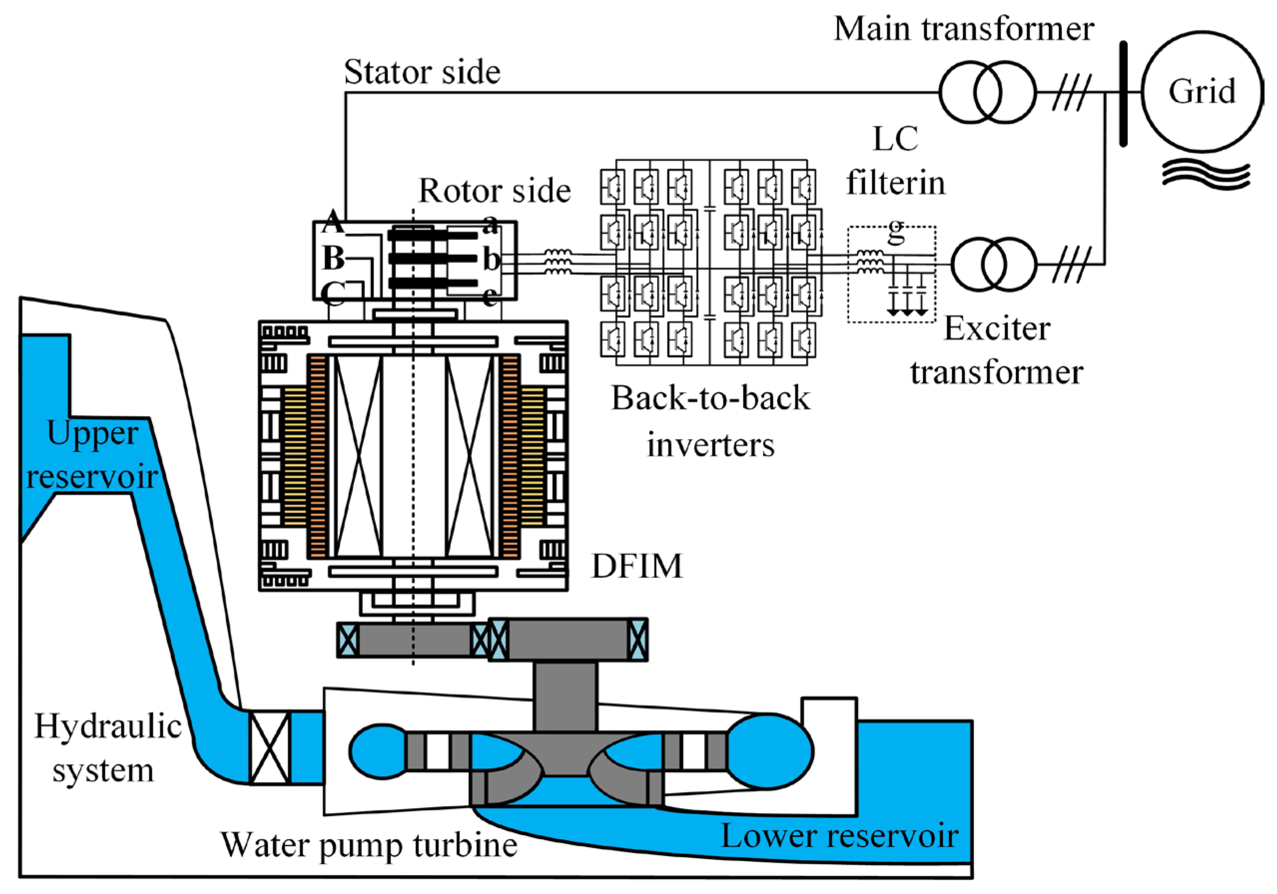
2. Model of DFIM for VSPS System

The VSPS system is mainly composed of a hydraulic system, a DFIM, back-to-back inverters, LC filtering modules, transformers, grid interfaces, etc., as shown in Figure 1. The VSPS system can pump water from the lower reservoir to the upper reservoir under pumping conditions, and release water from the upper reservoir to the lower reservoir under power generator conditions. It can operate during pumping and generator operations, forming reversible operating conditions. The DFIM is the core of the VSPS system with its stator winding directly connected to the power grid through the main transformer, and the three-phase rotor excitation winding leading out the phase lines through slip rings, connected to the power grid through back-to-back converters and excitation transformers. The rotor current of the DFIM is controlled to achieve operation under pumping and generator operations.
Therefore, the model of the DFIM in the d-q axis synchronous rotating coordinate system is established, and its magnetic flux equation in the d-q axis is
ψ s d = L s i s d + L m i r d ψ s q = L s i s q + L m i r q ψ r d = L m i s d + L r i r d ψ r q = L m i s q + L r i r q
where Ψsd, Ψsq, Ψrd, and Ψrq are the stator and rotor magnetic flux on the d-q axis coordinate system; isd, isq, ird, and irq are the stator and rotor current on the d-q axis coordinate system, respectively; Lm is the coaxial equivalent mutual inductance; Ls is the equivalent self-inductance of the stator; and Lr is the equivalent self-inductance of rotor.
The voltage equation of the DFIM in the d-q axis is
u s d = R s i s d + p ψ s d ω ψ s q u s q = R s i s q + p ψ s q + ω ψ s d u r d = R r i r d + p ψ r d ω ω r ψ r q u r q = R r i r q + p ψ r q + ω ω r ψ r d
where usd, usq, urd, and urq are the stator and rotor voltage on the d-q axis; isd, isq, ird, and irq are the stator and rotor current on the d-q axis, respectively; Rs and Rr are the stator and rotor resistances, respectively; p is a differential operator; and ω and ωr are synchronous angular velocity and rotor angular velocity, respectively.
The electromagnetic torque Te of the DFIM in the d-q axis is
T e = p L m i s q i r d i s d i r q

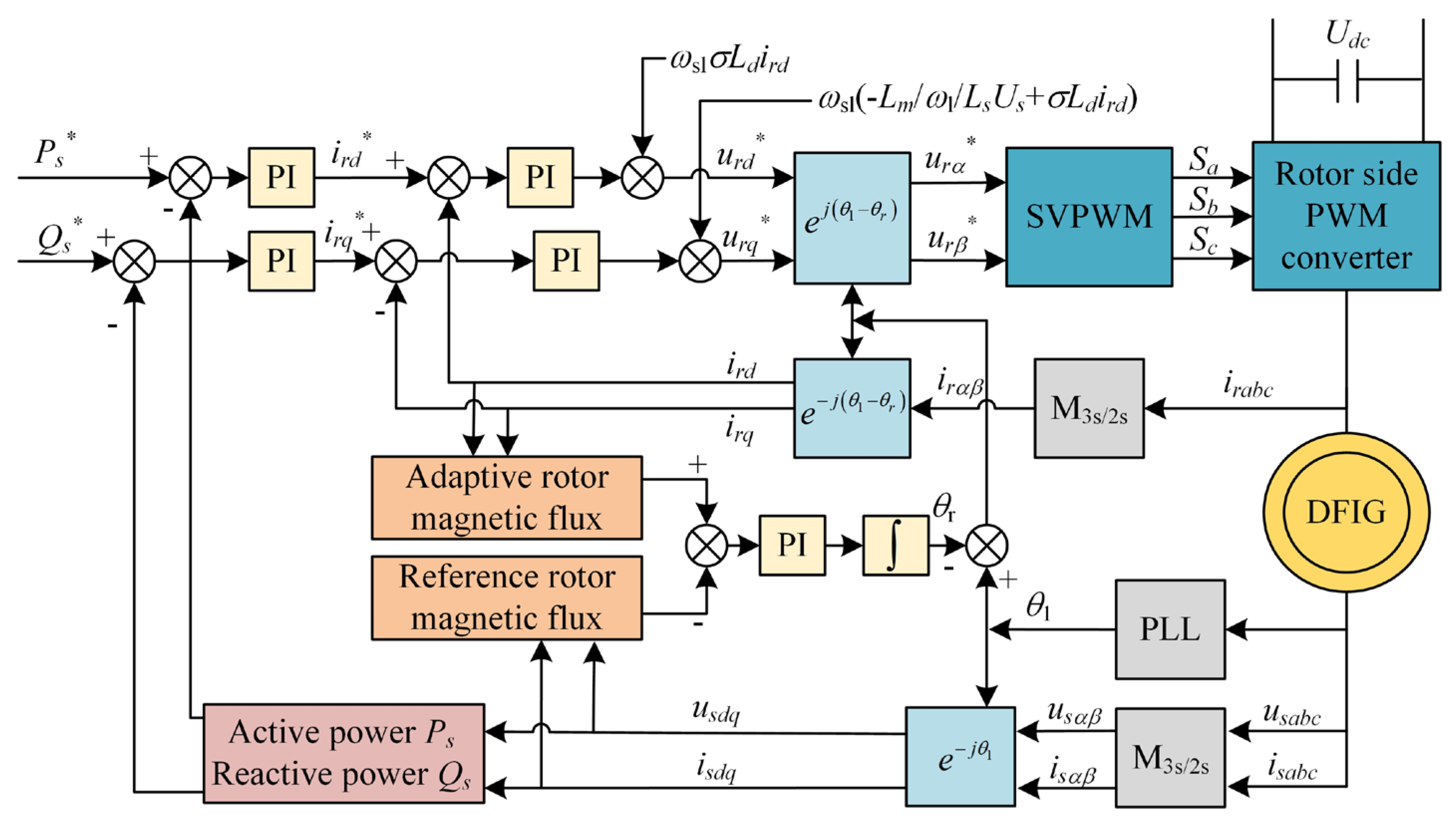
3. The Sensorless Closed-Loop Direct Detection Control

It is necessary to observe the stator flux in stator flux-oriented vector control, which increases the difficulty of control. However, if stator voltage-oriented vector control is adopted, the stator voltage of the VSPS system connected to the grid is the grid voltage, which is not affected by machine parameters and can be directly measured with accuracy.
If the d-q axis of the synchronous rotating coordinate system is oriented on the stator voltage Us, it is expressed as
ψ s d ψ s = U s / ω ψ sq 0 u s d = U s ω ψ sq u s q = 0 ω ψ sd
If the DFIM is connected to the grid, its stator is connected to the grid, and the stator current is not zero. It is achieved through a PI adaptive closed loop based on stator voltage feedback. The stator voltage axis component can be obtained as the reference model through the detection of stator side sensors and coordinate transformation. The current detection and coordinate transformation of the stator and rotor sides obtain the axial components of the stator and rotor currents, which can be substituted into the mathematical model of the DFIM to obtain the stator axis voltage as the adjustable model. The stator voltage calculated with Equation (4) is the variable that contains speed; the voltage usq* directly detected by the voltage sensor on the stator side and obtained through coordinate transformation does not include the rotational speed, so the slip angular velocity ωsl can be set as the output of the regulator, as shown in Equation (5), and the slip angle θsl can be obtained by integrating the slip angular velocity, as shown in Equation (6).
ω s l = k p + k i s u s q u s q *
θ s l = ω s l d t
Therefore, the sensorless closed-loop direct detection control is shown in Figure 2, where M3s/2r is the transformation from three-phase stationary coordinates to two-phase rotating coordinates. isa, isb, and isc are converted into isdq through M3s/2r; ira, irb, and irc are converted into irdq through M3s/2r; and Usq is obtained by isdq and irdq through Equation (5). Usa, Usb, and Usc are processed through M3s/2r to obtain Usq*, which is then subtracted from Usq and processed through PI to obtain ωsl. And the rotor angular velocity ωr is obtained by the difference between stator angular velocity ωs and slip angular velocity ωsl, as shown in Equation (7).
ω r = ω s ω s l
The coordinate axis vector of the DFIM obtained from Figure 2 is shown in Figure 3. The d-q axis is the two-phase synchronous rotation coordinate system, and the d′-q′ axis is the two-phase synchronous rotation coordinate system estimated by the speed observation. The correct orientation of sensorless control based on stator voltage closed-loop observation means that the estimated coordinate system coincides with the actual coordinate system. In assuming that the angle between the rotor current vector ir and the d-axis is θ, the error angle φ between the observed coordinate system and the actual coordinate system is defined as the positive value.
If the observed synchronous rotation coordinate system d′-q′ axis lags behind the real synchronous rotation coordinate system, the d-q axis coordinate system, as shown in Figure 3a, then i r cos θ i r cos θ + φ , i.e., the observed excitation component of the rotor current is greater than the actual value, i r d * = i r d i r d .
The dynamic performance of current loop control is good, and the rotor current phase will change, i.e., u s q * u s q . It can be seen that the observed slip frequency ωsl will inevitably increase, and the change in slip angle θsl will accelerate, leading to the increase in the rotation speed of the coordinate system, causing the oriented coordinate system to approach the actual coordinate system and coincide, enabling accurate observation of the rotational speed. Similarly, it can be concluded that if the observed synchronous rotation coordinate system is ahead of the real synchronous rotation coordinate system, the rate of change of the slip angle θsl slows down, ultimately achieving coincidence with the coordinate system and achieving accurate observation of the rotational speed.
The operation status of the DFIM is judged. If it operates in power generation, the control strategy for calculating the speed is based on Equation (5). If it operates in the pumping operation, the slip angular velocity ωsl is set as
ω s l = k p + k i s × u s q * u s q
The DFIM can operate normally in reversible working states from Equations (5) and (8). However, the closed-loop direct detection control relies on the accuracy of the parameters of the DFIM, and its accuracy decreases if the parameters of the DFIM change.

4. The Sensorless Control of Rotor Magnetic Flux Based on the MARS

The relationship between the active power Ps and reactive power Qs of the stator of the DFIM based on stator voltage orientation and the d-q axis currents of the rotor is expressed as follows:
P s 3 2 L m L s U s i r d Q s = 3 2 U s ω L s U s + ω L m i r q
Therefore, the active power Ps and reactive power Qs are controlled through rotor current d-q axis components. In the d-q axis synchronous rotating coordinate system controlled by the stator voltage vector, the rotor magnetic flux model is obtained from Equation (4):
ψ r q = σ L r L s L m i s q ψ r d = U s L m 2 + σ L r L s ω 1 L s L m σ L r L s L m i s d
where σ = 1 L m 2 L r L s .
The adaptive reference model for magnetic flux Ψrq and Ψrd was established from Equation (1), expressed as
ψ r q = L m i s q + L r i r α e j θ 1 θ r ψ r d = L m i s d + L r i r β e j θ 1 θ r
where i, i is the rotor current in the stationary coordinate system, which can be directly measured. e j θ 1 θ r is the coordinate transformation with an MARS angle, which changes the rotor current from the a-b axis to the d-q axis.
The actual measured magnetic flux model does not contain θr, while the estimated model contains θr. Therefore, Ψr is selected as the reference model, and Ψr is adopted as the adaptive model. The sensorless control of rotor magnetic flux based on the MARS is shown in Figure 4. PS* and QS* are subtracted from the actual PS and QS through PI to obtain ird* and irq*. Then, they are subtracted from the actual ird and irq through PI to obtain urd* and urq*. After the dq-αβ transformation, urα* and urβ* are obtained, and after Space Vector Pulse Width Modulation (SVPWM), they become Sa, Sb, and Sc signals. The signals are then passed through the machine-side controller and transmitted to DFIG.
In the MRAS identification system, global stability must be considered. Since the actual electrical constant is much smaller than the machine time constant, θr in Equation (11) can be regarded as the constant, and the adaptive model can be regarded as a linear state equation. Therefore, the designed system is stable. If there is a deviation in the rotor magnetic flux angle, there will be a certain error between the actual and estimated values of the rotor magnetic flux in the synchronous rotating coordinate system. The deviation in the rotor magnetic flux angle and the stator voltage are shown in Figure 5. The key to the proposed control strategy is to eliminate the angle difference between the two rotor magnetic fluxes.
The actual value of the rotor magnetic flux in the d-q axis synchronous coordinate system is assumed to be
ψ r d = ψ r cos θ 2 ψ r q = ψ r sin θ 2
Due to the deviation in the rotor magnetic flux angle, the measured value of the rotor magnetic flux in the d-q axis synchronous coordinate system is
ψ r d = ψ r cos θ 2 Δ θ ψ r q = ψ r cos θ 2 Δ θ
where Δθ is the rotor magnetic flux position angle error.
The control quantity ε is defined as
ε = ψ r d ψ r q ψ r d ψ r q
Substituting Equations (12) and (13) into Equation (14) yields
ε = ψ r sin θ cos θ 2 Δ θ cos θ sin θ 2 Δ θ
Simplifying Equation (15) yields
ε = ψ r 2 sin Δ θ
where Δ θ = θ 2 arctan L m i s q + L r i β r e j θ 1 θ r L m i s d + L r i α r e j θ 1 θ r .
Through continuous adjustment of the PI adaptive controller to θr, the error Δθ of the rotor flux position angle becomes increasingly smaller, and Ψr and Ψr remain substantially consistent, with the relative error ε approaching zero.

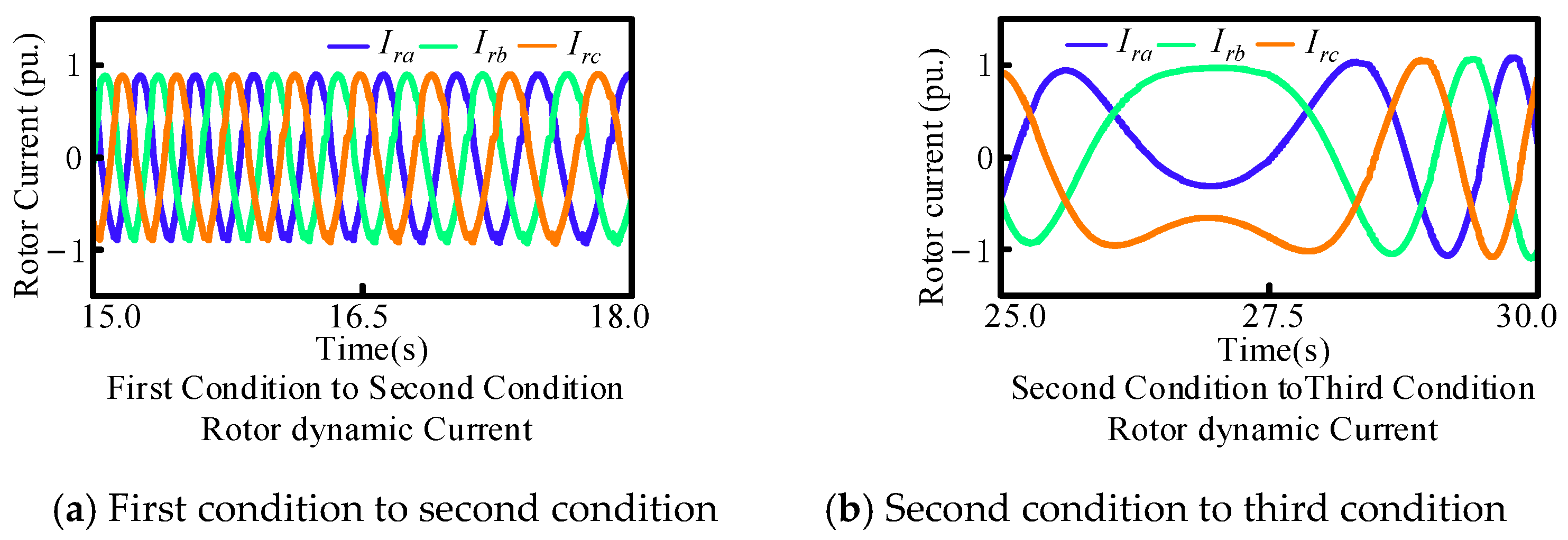
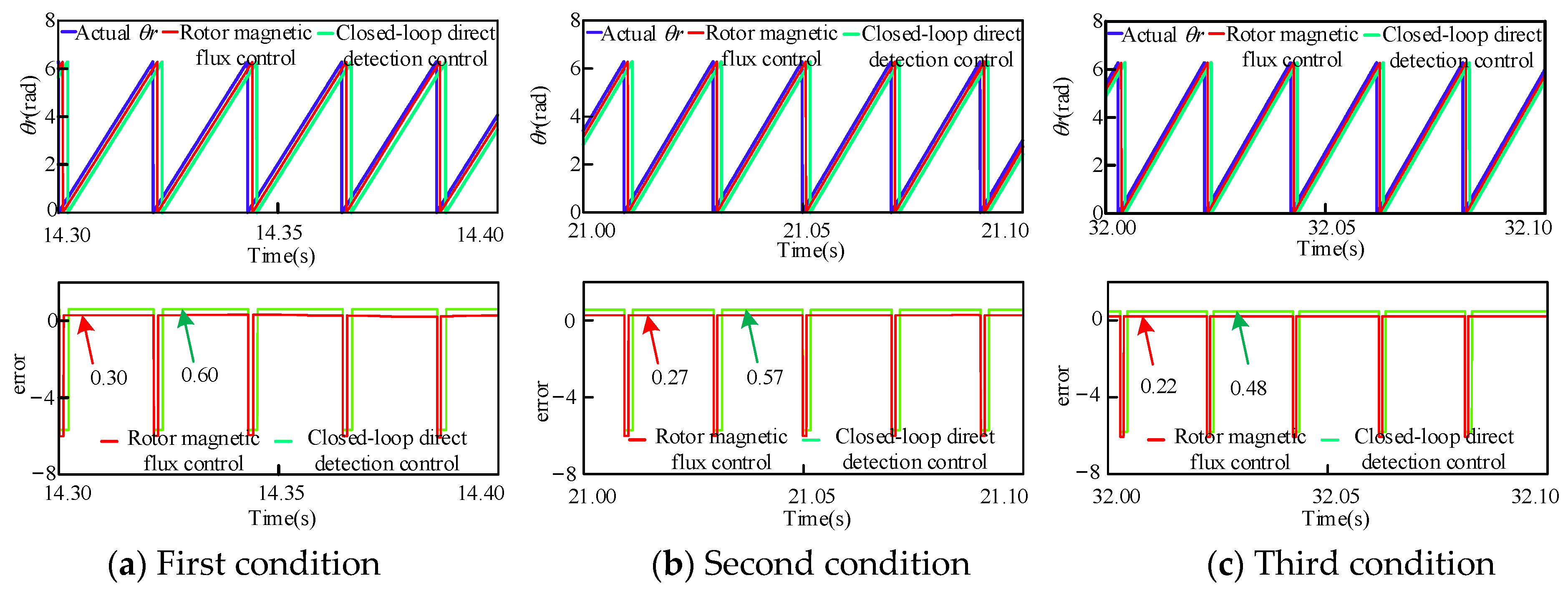
5. Simulation Verification

To verify the feasibility of the above-mentioned sensorless control of rotor magnetic flux based on the MARS and the sensorless closed-loop direct detection control, the simulation model was built with Matlab R2023b based on the test parameters of the large-scale VSPS system in Table 1. The VSPS system model in Matlab is shown in Figure 6. The VSPS system model is based on DFIG, and back-to-back converters on the rotor side and grid side are established, which are controlled by the rotor-side converter (RSC) and grid-side converter (GSC), respectively. The RSC adjusts the amplitude, frequency, and phase of the rotor excitation current to achieve constant frequency and constant voltage of the stator-side output voltage. The GSC maintains the stability of the DC bus voltage, transmits slip power to the grid, and can achieve reactive power control on the grid side. The simple model of the water pump turbine is constructed with transfer function.

5.1. Power Generation State

If the VSPS system operates in the power generation state, different operating modes are set. The first operating condition is set from 0 to 15 s, i.e., a speed of 0.93 pu and active power of 0.967 pu. The second operating condition is set from 20 to 25 s, i.e., a speed of 0.987 pu and active power of 1.03 pu. The third operating condition is set from 30 to 40 s, i.e., a speed of 1.02 pu and active power of 1.28 pu, achieving the speed change from sub-synchronization to super-synchronization. Then, 15 to 20 s is the transition time between the first operating condition and the second operating condition, similarly, 25–30 s is the transition time between the second and third operating conditions.
Subsequently, a simulation analysis of all operations during the power generation state was conducted: the rotor current variation is shown in Figure 7, the current changes from sub-synchronous to super-synchronous with the set operating conditions, and its amplitude increases with the increase in active power. When the speed approaches synchronous speed, i.e., 25–30 s, the rotor frequency tends to zero, resulting in asymmetric rotor current. The steady-state current in the first to third operations is shown in Figure 8a–c, respectively. It can be seen that the currents change from 0.88 pu to 0.925 pu and increase to 1.1 pu, and the currents change steadily with good sinuosity. During the period of 15–18 s, it is the transition phase from the first condition to the second condition, and in sub-synchronous operation, the current amplitude gradually increases. During the transition phase from the second operating condition to the third operating condition from 25 s to 30 s, there is a significant change in rotor current during the synchronous operation phase, as shown in Figure 9. Actually, Figure 7 and Figure 8 provide a better display of the static and dynamic rotor currents under a certain operating condition for all operating conditions.
In addition to rotor current, stator power, torque, and DC bus characteristics are important in power generation conditions. The reactive power remains basically zero, and the active power gradually increases from 0.967 pu to 1.03 pu, finally reaching 1.28 pu and stabilizing under the power generation state, as shown in Figure 10a. In this state, the torque changes from −0.85 pu to −0.89 pu, and finally reaches stability at −1.12 pu, as shown in Figure 10b. Moreover, the DC bus voltage remains constant under the power generation state and should not change during state transitions, as shown in Figure 10c. The simulation results of power, torque, and DC bus verify the correctness of the VSPS system model under power generation conditions.
The actual rotor speed and reference speed under the power generation state are shown in Figure 11a. If the DFIG changes from sub-synchronous speed to super-synchronous speed, the actual speed always follows the reference speed. When approaching the synchronous speed, the control system can still observe the speed well. The sensorless closed-loop direct detection control and the sensorless control of rotor magnetic flux based on the MARS are shown in Figure 11b,c, and both can track the actual speed well. The two sensorless control methods were tested separately, and the results show that they can track the actual speed well under all operating conditions.
The comparative simulation analysis shows that under steady-state conditions, the error of the sensorless control of rotor magnetic flux based on the MARS is within 0.3 for the three operating conditions, while the error of sensorless closed-loop direct detection control exceeds 0.5. The error of the sensorless control of rotor flux based on the MARS is smaller than that of sensorless closed-loop direct detection control, as shown in Figure 12a–c. Except in steady state, during dynamic operations, the error of the sensorless control of rotor flux remains basically unchanged, while the tracking error of sensorless closed-loop direct detection control is slightly larger than that in steady state, as shown in Figure 13, but both are within the allowable range. The results also demonstrate the superiority of the sensorless control of rotor flux based on the MARS.

5.2. Pumping State

In addition to power generation conditions, the VSPS system also operates in the pumping state. When the VSPS system is running in the pumping state, different operating modes are set to verify the feasibility of the simulation system in the pumping state. The first operating condition, i.e., speed of 0.93 pu, is set from 0 to 12 s; the second operating condition, i.e., speed of 0.99 pu, is set from 17 to 22 s; and the third operating condition, i.e., speed of 1.04 pu is set from 27 to 30 s, achieving the speed change from sub-synchronization to super-synchronization. The active power increased from −0.66 pu to −0.75 pu after 0–20 s, and then remained stable until 40 s. The dynamic process time of the speed and power are not set to be the same under the power generation condition, in order to demonstrate the effectiveness of its decoupling control.
The rotor current variation in all operations under the pumping state is shown in Figure 14; in the first to second operating conditions, the unchanged power resulted in a constant amplitude of rotor current, while in the third operating condition, the current increased with increasing power. Figure 15a–c show the steady-state current under the first to third operating conditions, respectively; the amplitude of power change is not large, and it can be seen that the current waveform changes from 0.7 pu to 0.75 pu, and that the current changes steadily with good sinuosity.
The period of 13.5–16.5 s is a transitional phase from the first operating condition to the second operating condition, in sub-synchronous operation. As the active power does not change, the current amplitude remains unchanged. During the transition phase from the second operating condition to the third operating condition from 22 s to 27 s, the rotor current changes from constant to variable during the synchronous operation phase, as shown in Figure 16a,b. The transformation of rotor current from sub-synchronous to super-synchronous under steady-state and dynamic pumping conditions demonstrates the correctness of the VSPS model.
Subsequently, the stator power, torque, and bus voltage under pumping conditions were analyzed. Figure 17a shows the stator power under the pumping state, where the reactive power remains basically zero and the active power gradually increases from −0.65 pu to −0.75 pu. The results show that the power change is relatively stable, and the active power and reactive power are well. In this state, the torque changes from 0.56 pu to 0.65 pu, the torque varies with power, and, due to the pumping state, the torque increases, as shown in Figure 17b. In addition, it is necessary for the DC bus voltage to remain constant under power generation conditions, as the bus voltage needs to be kept constant at all times under pumping conditions, as shown in Figure 17c.
Subsequently, the rotational speed was analyzed. The actual speed and reference speed of the rotor under the pumping state are shown in Figure 18a, gradually increasing from 0.93 pu to 0.99 pu near synchronous speed, and gradually rising to 1.04 pu over synchronous speed. The actual speed always follows the reference speed, and the tracking performance is good during dynamic changes. The sensorless closed-loop direct detection control and the sensorless control of rotor magnetic flux based on the MARS under the pumping state, as shown in Figure 18b,c, can track the actual speed well. It is evident that sensorless control with stator voltage orientation has significant errors with large fluctuations, but within the error range.
The results of the difference analysis between the two speeds obtained from the sensorless control of rotor flux based on the MARS and the sensorless closed-loop direct detection control and the actual speed are shown in Figure 19a–c. The error of the sensorless control of rotor magnetic flux based on the MARS is smaller than that of sensorless closed-loop direct detection control. The sensorless control error of rotor flux orientation is within 0.4, while the sensorless error of the stator voltage exceeds 0.7. Although there are small fluctuations in the active power of the system, it can quickly recover to a stable state. The error value of the pumping state is significantly higher than that of the power generation state, because the DFIG is mainly designed to operate under the power generation condition, resulting in a greater error in the pumping state than under the power generation condition. During bidirectional dynamic operation, as shown in Figure 20a,b, the tracking error is larger than that during stable operation, the maximum error of the sensorless control of rotor flux based on the MARS is 0.38, which is higher than the error value in the power generation state. The maximum error of the sensorless closed-loop direct detection control is 0.79, which is much higher than the error value of 0.66 in the power generation state, but both are within the allowable range.

6. Conclusions

This paper proposed a sensorless control for the DFIM based on the MRAS for a large-scale VSPS system, which abandons mechanical sensors and can effectively identify speed in pumping and generator operations. The main work of this study was concluded as follows: (1) The mathematical model of the VSPS system based on DFIG was established, and the vector control for the machine side and grid side based on stator voltage orientation was built. (2) The sensorless closed-loop direct detection control was established, and the positions of the rotor current vector under different operating conditions were analyzed. However, depending on the accuracy of the parameters of the DFIG and if the parameters change, the accuracy will decrease. (3) The sensorless control of rotor magnetic flux based on the MARS was established, which achieves high-precision speed estimation through the rotor flux position angle error between the reference model and the adaptive model. (4) The simulation of the VSPS system was carried out with MATLAB R2023b, and the operating status of the rotor current under all operating conditions was analyzed. The characteristics of power, torque, bus voltage, etc., were also analyzed, achieving stable operation under pumping and power generation conditions. Subsequently, a comparative analysis was conducted between the sensorless control of rotor magnetic flux based on the MARS and the sensorless closed-loop direct detection control. The maximum error between the former and actual speed was 0.3, while the maximum error between the latter and actual speed was 0.66 under the power generation conditions. The maximum error between the former and actual speed was 0.39, and the maximum error between the former and actual speed was 0.79 under pumping conditions. The results show that under reversible conditions, the sensorless control of rotor magnetic flux based on the MARS error is much smaller than the sensorless closed-loop direct detection control. In the case of system parameter changes and external disturbances, the proposed control strategy can effectively identify rotor position and speed in both pumping and generator operations, demonstrating superior robustness and practical applicability.

Author Contributions

Conceptualization, X.W. and Z.Z.; methodology, Z.M. and W.Y.; software, S.T., Y.L. and W.L.; validation, W.Y. and J.T.; formal analysis, Y.L. and W.L.; investigation, J.T.; data curation, W.L., W.Y. and W.L.; writing—original draft preparation, X.W.; writing—review and editing, Z.Z.; visualization, Z.M. and Y.L.; supervision, S.T.; resources, J.T. All authors have read and agreed to the published version of the manuscript.

Funding

This research received no external funding.

Data Availability Statement

The original contributions presented in the study are included in the article, further inquiries can be directed to the corresponding author.

Conflicts of Interest

Authors Zhi Zheng and Shuxin Tan were employed by the company Construction and Management Branch of China Southern Power Grid Energy Storage Co., Ltd. Authors Ziqiang Man, Wei Yan, Yu Lu, Jie Tian and Weiqun Liu were employed by the company NR Electric Co., Ltd. The remaining author declares that the research was conducted in the absence of any commercial or financial relationships that could be construed as a potential conflict of interest.

References

  1. Tiwari, R.; Nilsen, R.; Mo, O.; Nysveen, A. Control methods for operation of pumped storage plants with full-size back-to-back converter fed synchronous machines. IEEE Trans. Ind. Appl. 2023, 59, 6792–6803. [Google Scholar] [CrossRef]
  2. Chen, Y.; Xu, W.; Liu, Y.; Bao, Z.; Mao, Z.; Rashad, E.M. Modeling and transient response analysis of doubly-fed variable speed pumped storage unit in pumping mode. IEEE Trans. Ind. Electron. 2023, 70, 9935–9947. [Google Scholar] [CrossRef]
  3. Chen, Y.; Xu, W.; Liu, Y.; Mao, Z. Dynamical Response Comparison Between Variable Speed and Synchronous Speed Pumped-Storage Units in Turbine Mode. IEEE Trans. Energy Convers. 2024, 39, 2490–2503. [Google Scholar] [CrossRef]
  4. Munphal, S.; Suwankawin, S. A position-sensorless control of doubly fed induction machine by stator-equation-based adaptive reduced-order observer. IEEE Trans. Power Electron. 2022, 37, 15186–15208. [Google Scholar] [CrossRef]
  5. Krzeminski, Z. Sensorless multiscalar control of double fed machine for wind power generators. In Proceedings of the Power Conversion Conference-Osaka 2002, Osaka, Japan, 2–5 April 2002. [Google Scholar]
  6. Prystupa, D.; Huang, X.; Zhang, H.; Varvolik, V.; Buticchi, G.; Wang, S.; Zhang, X.; Li, J.; Gerada, C. Generalized high-frequency injection framework for sensorless control of synchronous reluctance machines. IEEE Open J. Ind. Electron. Soc. 2023, 4, 304–315. [Google Scholar] [CrossRef]
  7. Liu, Y.; Xu, W.; Zhu, J.; Blaabjerg, F. Sensorless control of standalone brushless doubly fed induction generator feeding unbalanced loads in a ship shaft power generation system. IEEE Trans. Ind. Electron. 2019, 66, 739–749. [Google Scholar] [CrossRef]
  8. Mondal, P.; Malakar, M.K.; Tripathy, P.; Krishnaswamy, S.; Saha, U.K. Robust observer design for sensorless voltage and frequency control of a doubly fed induction generator in standalone mode. IEEE Trans. Energy Convers. 2022, 37, 844–854. [Google Scholar] [CrossRef]
  9. Yang, J.; Tang, W.; Zhang, G.; Sun, Y.; Ademi, S.; Blaabjerg, F.; Zhu, Q. Sensorless control of brushless doubly fed induction machine using a control winding current MRAS observer. IEEE Trans. Ind. Electron. 2019, 66, 728–738. [Google Scholar] [CrossRef]
  10. Rauth, S.S.; Kastha, D.; Bajpai, P. A Modified MRAS based Sensorless Control of DFIG in Wind Energy Conversion System. In Proceedings of the 2022 IEEE IAS Global Conference on Emerging Technologies (GlobConET), Arad, Romania, 20–22 May 2022. [Google Scholar]
  11. Mbukani, M.W.K.; Gitau, M.N.; Naidoo, R.; Masike, L. A torque-based MRAS estimator for position/speed sensor-less control of DFIG systems. In Proceedings of the 2022 IEEE 1st Industrial Electronics Society Annual On-Line Conference (ONCON), Kharagpur, India, 9–11 December 2022. [Google Scholar]
  12. Zhou, Y.; Zhu, D.; Hu, J.; Zou, X.; Kang, Y. Phase Step Control in PLL of DFIG-Based Wind Turbines for Ultrafast Frequency Support. IEEE Trans. Power Electron. 2025, 40, 51–56. [Google Scholar] [CrossRef]
  13. Saihi, L.; Bakou, Y.; Ferroudji, F.; Tayebi, A.; Hadidi, A.; Ibrahim, O. A Novel Fuzzy-MRAS Observer of Wind Turbines Conversion Systems Based on DFIG. In Proceedings of the 2022 International Conference on Theoretical and Applied Computer Science and Engineering (ICTASCE), Ankara, Turkey, 29 September–1 October 2022. [Google Scholar]
  14. Lakhdar, S.; Ferroudji, F.; Roummani, K.; Koussa, K. Enhanced Sensor-Less Control of DFIG-Based Generators Using Hybrid MRAS-ANN Observer and PSO Parameter Optimization. In Proceedings of the 2023 14th International Renewable Energy Congress (IREC), Sousse, Tunisia, 16–18 December 2023. [Google Scholar]
  15. Gayen, P.K. An Enhanced Rotor Position/Speed Estimation Technique for Doubly Fed Induction Generator Using Stator-Side Reactive Current Variable in Model Reference Adaptive System. IEEE Trans. Ind. Electron. 2022, 69, 4409–4418. [Google Scholar] [CrossRef]
  16. Nguyen, A.T.; Lee, D.-C. Sensorless Control of DFIG Wind Turbine Systems Based on SOGI and Rotor Position Correction. IEEE Trans. Power Electron. 2021, 36, 5486–5495. [Google Scholar] [CrossRef]
  17. Gayen, P.K. Stator Flux Producing Current-Based Promoted Rotor Angle Estimator of Doubly-Fed Induction Generator for Encoderless Operations. IEEE Sens. J. 2021, 21, 15133–15141. [Google Scholar] [CrossRef]
  18. Bose, S.; Singh, S.P. Sensor-less Vector Control of DFIG Based Micro Wind Energy Conversion System. In Proceedings of the 2020 IEEE International Conference on Power Electronics, Smart Grid and Renewable Energy (PESGRE2020), Cochin, India, 2–4 January 2020. [Google Scholar]
  19. Wang, M.; Liu, J.; Jiang, L.; Tan, K.; Wang, Y. Position Sensorless Control of Permanent Magnet Synchronous Motor Based on Improved Model Reference Adaptive Systems. Energies 2025, 18, 2531. [Google Scholar] [CrossRef]
  20. Chakraborty, S.; Singh, B.; Panigrahi, B.K.; Das, S.; Roy, S. DMROGI-mEPLL Based Position Sensorless Disturbance Immune Control of a Wind and Solar Energy Driven Microgrid Amidst Abnormal Grid. In Proceedings of the 2024 IEEE Energy Conversion Congress and Exposition (ECCE), Phoenix, AZ, USA, 20–24 October 2024. [Google Scholar]
  21. Shanming, W.; Fang, W.; Shenghua, H. A Position Sensorless Control Method of Brushless Doubly Fed Independent Generator System. China Electr. Eng. J. 2016, 36, 1705–1713. [Google Scholar]
  22. Liu, Y.; Ai, W.; Chen, B.; Chen, K.; Luo, G. Control design and experimental verification of the brushless doubly-fed machine for stand-alone power generation applications. IET Electr. Power Appl. 2016, 10, 25–35. [Google Scholar] [CrossRef]
  23. Prasad, R.M.; Mulla, M.A. Rotor Position-Sensorless Algorithms for Direct Power Control of Rotor-Tied DFIG. IEEE Trans. Power Electron. 2021, 36, 6213–6217. [Google Scholar] [CrossRef]
Figure 1. The VSPS system.
Energies 18 02998 g001
Figure 2. The sensorless closed-loop direct detection control.
Energies 18 02998 g002
Figure 3. The rotor current vector of the DFIM.
Energies 18 02998 g003
Figure 4. The sensorless control of rotor magnetic flux based on the MARS.
Energies 18 02998 g004
Figure 5. The deviation in the rotor magnetic flux angle and the stator voltage.
Energies 18 02998 g005
Figure 6. Matlab model simulation of VSPS system.
Energies 18 02998 g006
Figure 7. Rotor current variation in all operations during power generation state.
Energies 18 02998 g007
Figure 8. Steady state of rotor current in different operations during power generation state.
Energies 18 02998 g008
Figure 9. Dynamic state of rotor current in different operations during power generation state.
Energies 18 02998 g009
Figure 10. Power, torque, and DC bus under power generation state.
Energies 18 02998 g010
Figure 11. Actual speed and observation speed under power generation state. (a) Actual speed and reference speed. (b) Sensorless closed-loop direct detection control. (c) Sensorless control of rotor magnetic flux based on MARS.
Energies 18 02998 g011
Figure 12. Steady state of rotor angle and error under power generation.
Energies 18 02998 g012
Figure 13. Dynamic state of rotor angle and error during power generation.
Energies 18 02998 g013
Figure 14. Rotor current variation in all operations during pumping state.
Energies 18 02998 g014
Figure 15. Steady state of rotor current in different operations during pumping state.
Energies 18 02998 g015
Figure 16. Dynamic state of rotor current in different operations during pumping state.
Energies 18 02998 g016
Figure 17. Power, torque, and DC bus under pumping state.
Energies 18 02998 g017
Figure 18. Actual speed and observation speed under pumping state. (a) Actual speed and reference speed. (b) Sensorless closed-loop direct detection control. (c) Sensorless control of rotor magnetic flux based on MARS.
Energies 18 02998 g018
Figure 19. Steady state of rotor angle and error under pumping state.
Energies 18 02998 g019
Figure 20. Dynamic state of rotor angle and error during pumping state.
Energies 18 02998 g020
Table 1. The test parameters of the large-scale VSPS system.
ParameterValueParameterValue
Grid voltage (kV)18Stator resistance (Ω)0.001113
Rated power (MW)300Stator leakage reactance (Ω)0.119
Rated frequency (Hz)50Rotor resistance (Ω)0.001225
DC bus voltage (V)7000Rotor leakage reactance (Ω)0.141
Variable ratio0.4287Excitation reactance (Ω)2.468
Disclaimer/Publisher’s Note: The statements, opinions and data contained in all publications are solely those of the individual author(s) and contributor(s) and not of MDPI and/or the editor(s). MDPI and/or the editor(s) disclaim responsibility for any injury to people or property resulting from any ideas, methods, instructions or products referred to in the content.

