Abstract
A diffusion absorption heat transformer is a completely thermally driven heat upgrading technology with significant application potential in low-grade thermal energy recovery. However, existing diffusion absorption heat transformers have problems such as complex circulation processes, limited solution flow rates, and insufficient stability due to their reliance on bubble pumps. A jet pump was proposed for application in a diffusion absorption heat transformer cycle to replace the bubble pumps in the original diffusion absorption heat transformer cycle. In the novel cycle, without electricity consumption, the diffusant gas was used as the primary flow of the jet pump to transport the solution, and the diffusion generation of the refrigerant was realized in the jet pump for more efficient and stable thermal energy upgrading. The performance of the novel cycle with H2O/LiBr/C5H10 or H2O/HCOOK/C5H10 as working fluids was analyzed based on a constructed theoretical model validated by numerical simulation. It was found that the performance of the jet pump was sensitive to the generator temperature and the pressure difference of the cycle. Increasing the temperature of the jet pump and reducing the temperature of the absorber were conducive to improving the COP. As a potential absorbent substitute for LiBr, HCOOK also led to slightly better performance in most cases.
1. Introduction
In line with the rapid development of societies, global energy consumption has continued to rise steadily in recent years. However, large amounts of low-grade waste heat have been exhausted in industries where substantial energy is consumed. There is significant potential for improvement in approaches to low-grade waste heat recovery and utilization. Meanwhile, abundant low-grade thermal energy resources such as solar and geothermal energy are available from natural sources. Therefore, efficiently utilizing these low-grade thermal energy sources represents a crucial pathway toward low-carbon and energy-efficient development. Thermal energy can be upgraded by thermally driven absorption heat transformers (AHTs), in which part of the medium-temperature heat can be converted into high-temperature heat for more effective utilization. AHTs are widely used in many fields, such as the petrochemical industry and in industrial waste heat recovery. AHTs are of great significance in achieving the cascade utilization of waste heat sources throughout the full temperature range, with improvements in energy utilization efficiency. In this way, less thermal energy is wasted and carbon dioxide emissions are reduced.
Typically, in a single-stage AHT system, the temperature of about half of the thermal energy can be increased, while the remaining thermal energy is emitted into the environment at a low temperature [1]. The system temperature lift is usually limited within 50 °C, and the coefficient of performance (COP) mostly ranges from 0.4 to 0.6 [2,3]. A variety of advanced cycles have been developed and proposed to improve energy efficiency or temperature lift with more flexibility and adaptability in wider applications.
The two-stage AHT is an advanced AHT that can widen the operating range in comparison with single-stage AHTs. Combined with the advantages of H2O/LiBr and 2,2,2-trifluoroethanol (TFE)/N-methy1-2-pyrrolidone (NMP) systems, Wang et al. [4] proposed a two-stage AHT with H2O/LiBr as the first stage and TFE/NMP as the second stage. The system not only provided higher available temperatures than the two-stage AHT using only H2O/LiBr but also achieved relatively higher COP and exergy efficiency than the two-stage AHT using only TFE/NMP. In order to achieve the same high-temperature lift with a simpler structure as that attained in the two-stage AHT, Rivera et al. [5] built a double-absorption heat transformer with H2O/LiBr as the working fluid. It could experimentally achieve a gross temperature lift of 48~74 °C and an internal COP between 0.12 and 0.37. A double-effect absorption heat transformer with TFE/tetraethylenglycol dimethylether (E181) was proposed by Zhao et al. [6]. It is suitable for situations in which the heat source temperature is high and the required temperature lift is low due to a higher COP but where there is a smaller temperature lift than that encountered with a single-stage AHT. A solution cross-type absorption–resorption heat transformer using NH3/H2O was proposed by Shen et al. [7]. The COP of the proposed system could reach 0.4049, with a gross temperature lift of 25 °C and a wide operating temperature range. The system had a lower optimal low-pressure value, which was suitable for applications with large pressure differences. A novel ammonia–water double absorption–resorption heat transformer was proposed by Jin et al. [8]. When the high/low pressure values were 1.5/0.36 MPa, the system could provide a temperature lift of more than 70 °C. Despite the lower COP, the working pressure was significantly lower than that of a conventional AHT. Thus, the requirements of the structural strength can be reduced and the operation stability of the system can be improved.
As a thermally driven pump for pressurization, mixing, or throttling, ejectors have been widely studied in fields of refrigeration systems and waste heat recovery [9,10]. An ejector was innovatively installed at the entrance of the absorber in an AHT by Shi et al. [11], and the solution from the generator was used to eject the refrigerant gas from the evaporator. The absorption temperature of the cycle was higher than that of a conventional cycle. Sözen et al. [12,13] investigated an ejector–AHT employing H2O/NH3 as the working pair, and they established a performance prediction model using artificial neural networks. The results demonstrated that the ejector can increase the output temperature by 5% and improve the exergy efficiency by 2.7%. In research conducted by Lin et al. [14], an ejector was installed between the generator and the condenser in an AHT to reduce the generator pressure, whereby the refrigerant vapor from the evaporator was used as the primary flow to entrain vapor from the generator into the condenser. Wang et al. [15] proposed a novel ejector–AHT by integrating an ejector and a low-pressure generator into the conventional AHT cycle. The solution from the high-pressure generator was further heated in the low-pressure generator to produce low-pressure vapor, thus increasing the concentration of LiBr solution. High-pressure vapor from the evaporator entrained the low-pressure vapor into the condenser through the ejector. At the same temperature, this cycle achieved a concentration difference with an increase of over 30% in comparison with a conventional AHT, with an increased temperature lift but a reduced COP.
Among these advanced cycles, most AHTs require mechanical pumps to provide the necessary pressure differences in the system. Thus, additional high-grade electrical energy supplements are essential to attain the temperature lift. At the same time, corrosion at high temperatures must be overcome due to the employment of mechanical pumps, particularly in AHTs with H2O/LiBr as a working pair.
To achieve an AHT cycle without electricity consumption, the addition of a bubble pump was proposed by Eriksson et al. [16] and Abrahamsson et al. [17], and a self-circulation AHT experimental platform was built. The system does not need a mechanical pump and is completely driven by heat with H2O/NaOH as the working fluid. However, in order to ensure a sufficient large pressure difference, the whole system had to be designed as huge and bulky, which was difficult to apply in industry.
Moreover, a diffusion absorption refrigerator (DAR) is a kind of thermally driven refrigeration technology with advantages of a very small pressure difference inside and no employment of mechanical pumps. Accordingly, inspired by the advantages of DAR, a new kind of diffusion absorption heat transformer (DAHT) was proposed in 2012 as an improved AHT [18]. The schematic diagram of an original DAHT is shown in Figure 1. The cycle performance of a DAHT driven by double bubble pumps with H2O/LiBr and R134a/TEGDME was evaluated by a constructed thermodynamic model [19]. The heat of 90 °C can be upgraded to 120 °C with a COP of about 0.170.
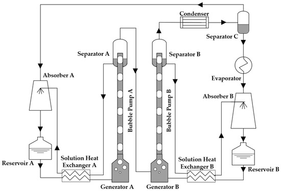
Figure 1.
Schematic diagram of an original DAHT with double bubble pumps.
Through the introduction and separation of diffusant, the DAHT can work in a condition of almost single pressure. It can be found that the height of DAHT is significantly lower than that of self-circulation AHT. The solution pumps and refrigerant pumps in conventional AHTs are replaced by two bubble pumps, which realize pumping solutions without any electrical energy consumption or mechanical moving parts. The corrosion problem of electric pumps can also be avoided.
A minority of studies on the DAHT were reported in the last decade. Other than the popular working pair H2O/LiBr, H2O/HCOOK has been experimentally verified to be feasible in a DAHT [20]. The COP of DAHT using HCOOK as refrigerant absorbent is similar to that using LiBr under constant temperature conditions, but HCOOK has the advantages of low cost, low corrosion, and good environmental compatibility [21]. Therefore, HCOOK still has great potential in practical applications. H2O/CaCl2 is also one of the substitute working pairs for DAHT. Zheng [22] experimentally observed that, although the H2O/CaCl2 working pair represented a relatively narrow concentration variation range, its vapor pressure variation range was comparable to that of H2O/HCOOK. H2O/CaCl2 was used in the DAHT cycle by Liu [23], and it demonstrated superior thermal stability than H2O/HCOOK and less corrosiveness than H2O/LiBr. This characteristic raises the upper limit of heat source temperatures for safe DAHT operation and facilitates the practical application of DAHT technology. Deep eutectic solvent was used in a bubble-pump-aided DAHT by Luo et al. [24]. The service life of DAHT can be prolonged and the operation stability can be improved significantly due to low corrosion and no crystallization risk of deep eutectic solvent. Compared with H2O/LiBr, deep eutectic solvents have a narrow normal operating range due to poor pumping capacity, but the optimal energy performance is similar.
As key components in an original DAHT, bubble pumps have great influences on cycle performance. Wang et al. [25] proposed a novel DAHT cycle with ejection boost, which reduced the influence of instability of bubble pumps on cycle performance. One of the bubble pumps used in the original DAHT was replaced by an ejector. COP was improved from 0.17 to about 0.27 when the heat was increased from 90 °C to 120 °C.
Nearly all the current DAHT cycles need to employ bubble pumps, and their heating performance is constrained by the capabilities of these bubble pumps. The operation of bubble pumps demands a heat source with suitable and stable temperatures, while their performance is influenced by multiple factors. Due to the small diameters of lifting tubes in bubble pumps, the flow rates are significantly lower compared to conventional mechanical pumps. Multiple lifting tubes can be employed for a large amount of flow, but instability caused by uneven bubble distribution will further escalate. The inherent instability and limited transport capacity of bubble pumps cannot be entirely eliminated, which limits the promotion and application of DAHTs in many fields.
An ejector with gas as the power source to transport the liquid is also called a jet pump. Inspired by the application of the ejector in DAHT with ejection boost, this paper proposes a novel DAHT driven by a jet pump whose functions of pressurization and mixing are utilized effectively. The novel DAHT eliminates the need for bubble pumps to transport solutions for the first time. The DAHT cycle is innovatively improved by the employment of a jet pump, enabling pressurization and solution pumping with thermal driving. Compared to the original DAHT with double bubble pumps and the DAHT with ejection boost and one bubble pump, the novel DAHT further simplifies the cycle configuration without diffusant absorbent and avoids performance limitations and influences caused by bubble pumps. The cycle working fluids consist of diffusant, refrigerant, and absorbent, reducing influencing factors and parameters with significantly enhanced stability and reliability. Although conventional AHTs present relatively higher cycle performance, they require quite high-grade electrical energy input in solution pumps and refrigerant pumps. In contrast, no electrical energy but entirely thermal energy is spent inside the novel DAHT cycle, which is of great applicability for low-grade thermal heat recovery, especially in electricity-scarce regions.
In this paper, a thermodynamic model of the DAHT driven by a jet pump is theoretically constructed on the base of the original DAHT model. The jet pump flow model was validated with numerical simulation. The cycle performance under different temperature conditions with different pressure differences was investigated. The feasibility of weakly corrosive HCOOK as an absorbent substitute to LiBr was theoretically evaluated.
2. Cycle Description
Unlike conventional AHT, the novel DAHT cycle incorporates a diffusant in addition to the refrigerant and absorbent. The diffusant must have a boiling point significantly lower than that of the refrigerant, be immiscible with liquid refrigerant, and exhibit high saturation pressure at input temperatures to serve as the primary flow of Jet Pump. This paper refers to the solution before refrigerant generation as dilute solution and the solution after refrigerant generation as concentrated solution. The principle of novel DAHT cycle driven by a jet pump is representatively described with H2O as the refrigerant, LiBr as the absorbent, and C5H10 as the diffusant. In the cycle shown in Figure 2, heat is absorbed in Generator, Jet Pump, and Evaporator but released in Condenser A, Condenser B, and Absorber.
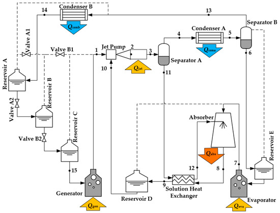
Figure 2.
Schematic diagram of a DAHT driven by a jet pump.
The C5H10 liquid is heated in Generator and evaporated into high-pressure gas, ready to be the primary flow of Jet Pump. The high-pressure C5H10 gas entrains the aqueous LiBr solution from Reservoir D, and the two are mixed in Jet Pump. During the mixing process of fluid in Jet Pump, since the chemical potential of H2O in gas phase is smaller than that in dilute aqueous LiBr solution, H2O in aqueous LiBr solution evaporates and diffuses into C5H10 gas, while the concentration of aqueous LiBr solution increases. Due to the latent heat of evaporation of H2O, heat energy has to be supplied to Jet Pump, which is different from a conventional adiabatic ejector or jet pump. Jet Pump requires heat input for the diffusion generation of refrigerant while achieving entrainment pressurization of aqueous LiBr solution.
In Separator A, the mixture of C5H10 and H2O vapor from Jet Pump is separated from the concentrated aqueous LiBr solution. The mixture vapor flows from the top of Separator A to Condenser A. When the mixture vapor is cooled to a certain temperature in Condenser A, H2O condenses to liquid, with heat released to the environment. However, C5H10 still maintains gas phase, which ensures the separation of H2O from C5H10. Since C5H10 is insoluble in water, the liquid out of Separator B can be supposed to be water alone, while the gas phase is C5H10 along with very little H2O vapor. After cooling to a lower temperature in Condenser B, C5H10 is also completely condensed into liquid and temporarily stored in Reservoir A and Reservoir B by gravity. The liquid H2O from Separator B is temporarily stored in Reservoir E by gravity and ready for evaporation in Evaporator.
The concentrated aqueous LiBr solution out of Jet Pump then flows from Separator A to Absorber under the action of gravity. It is also preheated in Solution Heat Exchanger by the high-temperature dilute aqueous LiBr solution from Absorber. It enters Absorber and merges with H2O vapor from Evaporator. Due to the absence of C5H10 in Absorber, nearly all of the gas phase is H2O. H2O can be absorbed by concentrated aqueous LiBr solution under the influence of this chemical potential difference. During the absorption process of decreasing concentration of aqueous LiBr solution, a significant amount of high-temperature heat is released from Absorber. As the absorption heat is gradually accumulated, the temperature of the heat released by Absorber can be eventually higher than the temperature of Generator and Evaporator, which is a presentation of temperature lift by the cycle. As the absorption process is completed, diluted aqueous LiBr solution is temporarily stored in Reservoir D after cooling in Solution Heat Exchanger and is ready to be ejected into Jet Pump later.
The operation of the cycle comprises two modes by valve switching:
Liquid accumulated mode: The liquid accumulated mode needs to be switched with Valve A1 and Valve A2 opened and Valve B1 and Valve B2 closed. At this time, the C5H10 liquid stored in Reservoir C enters Generator by gravity and is heated to high-pressure gas as primary flow of Jet Pump.
Liquid supplied mode: The liquid supplied mode needs to be switched with Valve A1 and Valve A2 closed and Valve B1 and Valve B2 open. After the momentary pressure balance between Reservoir B and Reservoir C, the liquid-phase C5H10 in Reservoir B can flow to Reservoir C under the action of gravity. C5H10 liquid from Condenser B is accumulated in Reservoir A until the cycle is switched back to the liquid accumulated mode, while Generator and all other components work without interruption. When Reservoir B is emptied, Valve B1 and Valve B2 are then switched closed, Valve A1 and Valve A2 are switched opened, and the system is switched back to the liquid accumulated mode again.
Due to pressure equilibration between reservoirs and components through pipelines, all components in the cycle exhibit nearly identical pressures except at Generator outlet and the secondary flow inlet of Jet Pump if the pressure loss caused by friction resistance of pipelines and components is neglected. In the cycle, the flow of all liquids except the secondary flow of Jet Pump is driven by gravity. Therefore, there are certain requirements for the relative height position of each component, as simply indicated in Figure 2.
In conventional AHTs, the generation and absorption of working pairs are influenced by the pressure differences provided by mechanical pumps. However, in the novel DAHT driven by a jet pump, these processes are carried out under almost the same pressure and are determined by the refrigerant partial pressure difference with diffusant added and separated. It is feasible for a jet pump in applications with a small total pressure difference; thus, electric solution pumps and refrigerant pumps in conventional AHTs can be displaced. The cycle configuration of the proposed novel DAHT is also simpler due to the employment of a jet pump instead of bubble pumps in an original DAHT. A jet pump also makes more sufficient and more stable contact between diffusant and solutions. In this way, the diffusion of refrigerant can be enhanced and the stability and reliability of the system are improved.
3. Jet Pump and Cycle Model
3.1. Jet Pump Model
A jet pump can bring about the blending of dilute solution and diffusant and increase the pressure of ejected solution in the novel DAHT. As shown in Figure 3, a jet pump consists of a nozzle, a suction chamber, a mixing chamber, and a diffuser. A heat exchange chamber is also added at the outlet to simplify the heat exchange process where the calculation of the entrainment ratio is not concerned. The heat exchange chamber of the jet pump is not discussed in this section but described with other components in the cycle model.
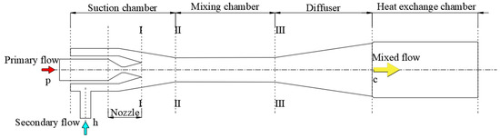
Figure 3.
Structure of a jet pump.
The function of the jet pump can be explained as follows. High-pressure primary flow expands adiabatically in the nozzle with pressure decrease. A low-pressure zone can be formed for drawing secondary flow when the primary flow enters the suction chamber at supersonic speed. The secondary flow enters the jet pump due to the pressure difference and then is mixed with the primary flow in the mixing chamber for kinetic energy exchange. The mixed flow from the mixing chamber is pressurized in the diffuser. The pressurization of secondary flow is realized in this way. The mixed flow is then heated in the heat exchange chamber for refrigerant diffusion and evaporation.
In this cycle, the primary flow of the jet pump is mainly C5H10 gas, with a very small amount of H2O vapor according to the phase equilibrium of C5H10 and H2O. The secondary flow of the jet pump is aqueous LiBr solution. The mixed flow is a mixture of vapor and liquid.
The calculation and design of a jet pump mainly refers to the theory by Sokolov [26]. The converted isentropic velocity of fluid can be derived with relevant thermodynamic parameters in mass, momentum, and energy conservations. A calculation model without a heat exchange chamber was established by theoretical derivation and an empirical coefficient correction method with high reliability. The principal calculation formulas of the entrainment ratio are listed as follows.
By employing velocity coefficients for correcting non-isentropic expansion and compression processes, the momentum equation and isentropic velocity conversion formula between section II and section III in the cylindrical mixing chamber are:
The critical velocity at any position of a jet pump is:
The critical cross-sectional area of any fluid in a jet pump is:
In Equations (1)–(7), m is the mass flow rate of fluid, kg/s; w is the fluid velocity, m/s; P is the static pressure, Pa; f is the cross-sectional area of the fluid inside the jet pump, m2; λ is the converted isentropic velocity of fluid; φ is the velocity coefficient inside the jet pump; k is adiabatic index; v is the gas specific volume, m3/kg; q is the converted mass velocity; and Π is the relative pressure. In the subscript, p represents the primary flow; h represents the secondary flow; c represents the mixed flow at the outlet of the diffuser; and * represents the critical condition.
The equation of the characteristic curve of a gas–liquid jet pump is:
The optimal area ratio is:
In Equations (8) and (9), u is the entrainment ratio to evaluate the performance of a jet pump, u = mh/mp; ΔPc is the pressure difference of a jet pump, that is, the pressure difference between the jet pump outlet and the ejected liquid, kPa; εp* is the critical relative density of primary flow; and vcg is the gas specific volume at the diffuser outlet, m3/kg.
In Reference [26], theoretical calculations and experimental investigations were performed on multiple ejectors. Based on experimental and theoretical data, velocity coefficients were introduced to correct deviations between theoretical values and actual results. In the gas–liquid jet pump, the values of the four velocity coefficients used to calculate the entrainment ratio are φI = 0.95, φII = 0.925, φIII = 0.83, and φII–III = 0.975. The entrainment ratio u can be finally solved according to the above formula.
3.2. Cycle Model
The process of refrigerant generation and absorption in the DAHT cycle driven by a jet pump is similar to that of the original DAHT with double bubble pumps. Therefore, based on the thermodynamic model verified by experiments in References [19,20], combined with the jet pump model, the cycle model of the novel DAHT can be established. In order to simplify the calculation, the following assumptions are made in the cycle performance analysis:
- (1)
- The temperatures of Jet Pump (Tjet), Generator (Tgen), Evaporator (Teva), Condenser A (Tcona), Condenser B (Tconb), and Absorber (Tabs) in the cycle are specified.
- (2)
- The minimum temperature difference of Solution Heat Exchanger is specified as 5 °C at the hot end.
- (3)
- In addition to the components that need heat exchange in the cycle, pipelines, separators, and reservoirs are all considered as adiabatic.
- (4)
- In addition to the pressure at the outlet of Generator, the pressure in the cycle is mainly determined by the saturated vapor pressure of H2O in Evaporator, while ignoring the flow pressure loss of heat exchange components, pipelines, separators, and liquid reservoirs caused by friction resistance.
- (5)
- The diffusant C5H10 is insoluble in liquid H2O or aqueous LiBr (or HCOOK) solution, namely, there is no C5H10 at state points 11 and 6 (the maximum molar concentration of C5H10 in liquid mixture of C5H10 and H2O was estimated to be very small, about 9.378 × 10⁻⁵%, by Peng-Robinson equation at 37 °C and 70.2 kPa, which is similar to the design condition at state point 6); LiBr and HCOOK do not volatilize, namely, there is no LiBr (or HCOOK) at state point 4. Therefore, C5H10 can be considered insoluble in H2O.
Compared with the original DAHT, the greatest feature of the proposed novel DAHT driven by a jet pump is the thermally driven jet pump instead of bubble pumps. Accordingly, based on theories from the thermodynamic model of the original DAHT in Reference [19] and pneumatic jet pump model in Reference [26], a model of the novel DAHT driven by a jet pump can be constructed with the employment of mass and energy conservation equations. The mass and energy conservation equations of each component are shown in Table 1, with corresponding state points in Figure 2. In Jet Pump, as an example, the mass flow rate of mixed flow at state point 3 (m3) is equal to the sum of the mass flow rate of cyclopentane at state point 1 (m1) and the mass flow rate of dilute solution at state point 10 (m10), while the total enthalpy value of the mixed flow at state point 3 (m3h3) is equal to the sum of the total enthalpy value of cyclopentane at state point 1 (m1h1), the total enthalpy value of dilute solution at state point 10 (m10h10), and the heat absorbed by Jet Pump (Qjet).

Table 1.
Thermodynamic equations for components.
The parameters of each state point in Figure 2 can be obtained by the model in a specified working condition. Some dimensionless factors are also defined to evaluate the cycle performance, including the entrainment ratio u of Jet Pump, the proportion of heat input to Generator in the system βgen, and the coefficient of performance COP:
where Qgen, Qjet, and Qeva are the heat input to Generator, Jet Pump, and Evaporator and Qabs is the heat released by Absorber.
To compare cycle performance with the DAHT with double bubble pumps [21] and the DAHT with ejection boost [25], the design conditions of the novel DAHT are the same as those of the two DAHTs, including temperatures of components, along with heat exchange, and solution lifting pressure difference, as listed in Table 2.
Table 2.
Design temperatures and design pressure difference.
3.3. Validation of Jet Pump Flow Model
A computational fluid dynamics (CFD) simulation of a jet pump was also conducted to further verify the feasibility of using the diffusant to entrain the aqueous LiBr solution and to validate the jet pump flow model in Section 3.1. The secondary flow inlet of the jet pump is simplified as an axial annular inlet. Due to the axial symmetry of the jet pump, it can be simplified as a two-dimensional axisymmetric model. For turbulence model selection, Valle et al. [27] and Croquer et al. [28] concluded in their ejector studies that simulations using the Standard k-ε turbulence model exhibit the smallest errors compared to experimental data. Therefore, this study employs the Standard k-ε turbulence model for the numerical simulation of jet pump flow.
To verify the reliability of the selected models and computational settings for jet pump numerical simulations in this paper, the gas–liquid ejector from Gu [29] was simulated. During the simulation, the primary flow pressure and mixed flow pressure were fixed, while the secondary flow pressure was varied to investigate its impact on ejector performance. Except for the fluid operating parameters specified in the reference, the selected model and computational settings remained identical to those used in this paper. As shown in Figure 4, the entrainment ratio gradually increases with rising secondary flow pressure. Although deviations between simulated and reference values slightly increase at higher secondary flow pressures, the overall average error remains approximately 5% and the trend of entrainment ratio variation aligns consistently. This confirms the reliability of the CFD simulation model in this paper.
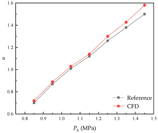
Figure 4.
CFD simulation model verification.
In the DAHT cycle driven by a jet pump, the primary flow of Jet Pump is the diffusant C5H10, the primary flow temperature is the temperature of Generator, and Generator pressure is the saturated pressure, about 358.4 kPa. The secondary flow is aqueous LiBr dilute solution from Reservoir D and the solution temperature after heat exchange is about 96.2 °C. The mixed flow pressure is the saturation pressure of H2O at the evaporation temperature of 90 °C, which is about 70.2 kPa. The static pressure difference caused by the height difference from Reservoir D to Jet Pump is specified as 20 kPa. The pressure of Reservoir D is the same as that of Evaporator, so the pressurization of Jet Pump to the solution is 20 kPa. Table 3 is the specific working parameters of Jet Pump under the design conditions in CFD simulation.
Table 3.
Working parameters of jet pump in CFD simulation.
Through the calculation of the jet pump model in Section 3.1, the entrainment ratio of the jet pump under the design condition is 2.73. When the mass flow rate of the primary flow is 0.1 kg/s, the jet pump under the design condition is designed based on the method of Reference [26]. The specific structure size is shown in Figure 5.
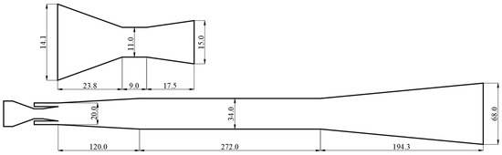
Figure 5.
The structure size of jet pump (in mm).
CFD simulation was performed on the jet pump under design conditions, with the variation in internal flow field shown in Figure 6. The simulation yielded that mp = 0.0924 kg/s and mh = 0.2284 kg/s. The result of the entrainment ratio u in CFD simulation was 2.50, which was close to the results by the theoretical model in Section 3.1. The relative error between the results by theoretical model and CFD simulation was 9.2%, which is acceptable to validate the accuracy of the constructed theoretical model.
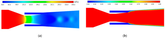
Figure 6.
Variation in internal flow field in jet pump (near the nozzle and the suction chamber): (a) pressure contour; (b) volume fraction contour of gas.
Through Figure 6a, it can be seen that high-pressure primary flow is adiabatically expanded through the nozzle and becomes a high-speed fluid entering the suction chamber. The fluid pressure is significantly reduced and a low-pressure zone is formed in the suction chamber. There is a pressure difference between the suction chamber and the secondary flow inlet, which can entrain the solution. Figure 6b showed the volume fraction contour of gas. Although the mass flow rate ratio between the secondary and primary flows achieved 2.50, their volume flow rate ratio remained small at approximately 0.015.
4. Results and Discussions
In the design condition, as shown in Table 2, the performance of the novel DAHT driven by a jet pump was calculated based on the constructed thermodynamic model. When the primary flow m1 is specified as 0.1 kg/s, parts of the cycle calculation results are summarized in Table 4. The thermophysical properties of aqueous LiBr or HCOOK solutions refer to the References [22,30,31].
Table 4.
Results of the DAHT cycle in the design condition.
To evaluate the cycle performance of the novel DAHT under diverse environments, heat source conditions, and output heat requirements, the influences of temperature parameters and pressure difference within a certain variation range on the performance of the jet pump and cycle are analyzed. The cycle performance with the absorbent of LiBr or HCOOK is also compared.
4.1. Effect of Temperature and Pressure Difference on u
Jet Pump is a critical component of the novel DAHT for achieving solution pressurization and circulation. The entrainment ratio u is the most essential performance parameter of Jet Pump. The larger the u, the more dilute aqueous LiBr solution can be injected per unit mass of C5H10 gas, which is beneficial for improving the refrigerant generation process and circulation performance in Jet Pump. As shown in Table 4, the density and specific heat capacity of dilute aqueous LiBr solution are close to those of dilute aqueous HCOOK solution at the same temperature and pressure. Since u is mainly determined by the inlet and outlet pressures of Jet Pump but hardly influenced by the density and specific heat capacity of the liquid, the values of u in the cycle are very close to each other in the employment of the two absorbents. Therefore, results of u in the cycle with HCOOK are removed for a clear view. It can be seen from Figure 7 that u is obviously influenced by Teva, Tgen, and ΔPc. u keeps almost constant at 2.73 with the increase in Tabs and Tconb because the temperature of Absorber and Condenser B have no effect on the pressure of primary flow, secondary flow, and mixed flow of Jet Pump.
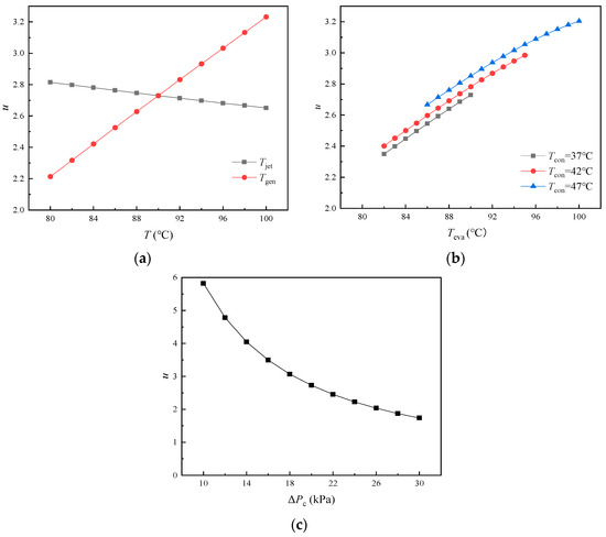
Figure 7.
Variations in u with temperature and pressure difference: (a) variations in u with Tjet and Tgen; (b) variations in u with Teva at different Tcona; (c) variations in u with ΔPc.
In Figure 7a, u decreases slightly with the increase in Tjet. With Tjet increases, the temperature of the solution entering Jet Pump rises, resulting in an increase in the gas specific volume in Jet Pump as well as u. The C5H10 liquid is heated in Generator and evaporated into high-pressure gas, ready to be the primary flow of Jet Pump. The C5H10 liquid is heated in Generator and evaporated into high-pressure gas as primary flow of Jet Pump. It is found that u increases significantly with the increase in Tgen due to the simultaneous pressure increase of primary flow. The ejecting capability of Jet Pump can be improved at higher pressure of the primary flow. In Figure 7b, high Tcona is slightly conducive to improving u due to the increase in residual H2O vapor concentration in the diffusant C5H10 and the minor increase in total pressure of primary flow. It is also found that u showed a high sensitivity to the change in Teva, and u increased sharply with the increase in Teva. Since the pressure difference between suction pressure and outlet pressure of Jet Pump is specified as constant, the compression ratio (Pc/Ph) of Jet Pump can be reduced with high outlet pressure caused by high Teva. The temperature of Condenser A and Evaporator make great influences on the operation of the system. When the temperature exceeds a certain range, the system cannot run normally. Since the partial pressure of C5H10 gas as well as the condensation temperature of diffusant can be changed with different H2O vapor concentrations in the diffusant at different Condenser A temperatures or Evaporator temperatures, the system can run in a limited Evaporator temperature range at different Condenser A temperatures. In Figure 7c, as the pressure difference ΔPc increases, the suction pressure decreases and the compression ratio of Jet Pump increases when the outlet pressure of Jet Pump is constant. The larger the compression ratio is, the weaker the ejecting capability of Jet Pump is; that is why u decreases more and more slowly. The pressure difference ΔPc of Jet Pump is determined by the frictional resistance and height difference between Jet Pump and Evaporator.
4.2. Effect of Temperature and Pressure Difference on βgen
βgen is the ratio of the heat input to Generator to the total heat input to the cycle. It has been found that more than half of the heat input to the DAHT is expended by Generator. So, it is necessary to pay close attention to the component with higher energy consumption like Generator for higher performance. It can be seen from Figure 8 that Tjet and Tabs have great influences on βgen. Tconb can only affect the temperature of liquid C5H10 entering Generator. The heat required by Generator (Qgen) can be slightly reduced at high Tconb. However, due to the smaller proportion of sensible heat compared to latent heat, βgen at various Tconb remains almost constant at about 0.582 in the cycle with LiBr and at about 0.557 in the cycle with HCOOK. When LiBr is replaced by HCOOK, Qgen remains unchanged and more heat needs to be supplied to Jet Pump and Evaporator (Qjet and Qeva) due to more H2O vapor generated from dilute aqueous HCOOK solution at the same temperature. Thus, the cycle with the absorbent of HCOOK instead of LiBr represents a smaller βgen.
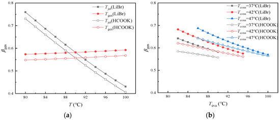
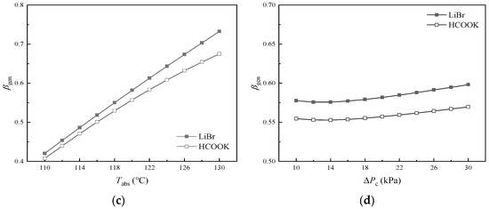
Figure 8.
Variations in βgen with temperature and pressure difference: (a) variations in βgen with Tjet and Tgen; (b) variations in βgen with Teva at different Tcona; (c) variations in βgen with Tabs; (d) variations in βgen with ΔPc.
In Figure 8a, βgen decreases sharply with the increase in Tjet. As Tjet increases, the increase in Qjet and Qeva results from more H2O vapor generated from solution. It is found that Qgen as well as βgen is a bit larger at higher Tgen. In Figure 8b, it is found that βgen decreases with the increase in Teva at constant Tcona in the operating temperature range and increases slightly with the increase in Tcona at constant Teva. As Tcona increases, less heat is required by Evaporator (Qeva) and more H2O vapor is left in the diffusant gas, which results in a slight increase in Qgen and decrease in Qjet. As Teva as well as Evaporator pressure increases, the pressure of refrigerant vapor in Absorber increases. More refrigerant can be absorbed by the absorbent, which results in a decrease in the concentration of dilute solution. Consequently, the dilute solution in Jet Pump can generate more H2O, leading to an increase in both Qeva and Qjet, while βgen decreases accordingly. The difference in βgen between the cycle with HCOOK and LiBr becomes smaller at higher Teva. In Figure 8c, with the increase in Tabs, βgen increases significantly because the aqueous LiBr (or HCOOK) solution is concentrated, with less H2O vapor generated as well as less Qjet and Qeva. The difference in βgen between the cycle with HCOOK and LiBr becomes larger at higher Tabs. In Figure 8d, as ΔPc increases, βgen first decreases slowly and then increases slowly, reaching the lowest βgen at about 13 kPa. Qgen is constant. When ΔPc is less than 13 kPa, u is sensitive to the change in ΔPc and increases rapidly with the decrease in ΔPc. Although more solutions are ejected, the amount of refrigerant per unit dilute solution decreases significantly. The less heat that is absorbed by Jet Pump, the larger the βgen is. When ΔPc is larger than 13 kPa, with the increase in ΔPc, u decreases and less solutions are ejected. Although the amount of refrigerant per unit dilute solution increases, the total amount of generated refrigerant as well as the heat absorbed by Evaporator decreases, which leads to larger βgen.
4.3. Effect of Temperature and Pressure Difference on COP
COP can directly reflect the energy efficiency of the cycle, which is an important cycle performance indicator. It can be seen from Figure 9 that Tjet and Tabs have great influences on COP. High COP can be usually achieved with small βgen. COP is almost not affected by Tconb and is maintained at about 0.180 using LiBr and about 0.183 using HCOOK. When LiBr is replaced by HCOOK with a smaller βgen, Qabs is also increased due to more water vapor being absorbed and more heat released. Thus, COP can be improved by the substitution of absorbent in most cases. Significantly, the COP lead of the cycle with HCOOK vanishes at high Tjet, high Teva, and low Tabs due to the sharp increase in Qjet and Qeva.
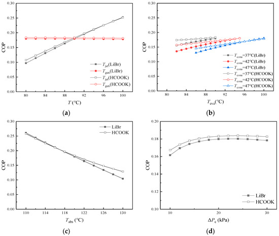
Figure 9.
Variations in COP with temperature and pressure difference: (a) variations in COP with Tjet and Tgen; (b) variations in COP with Teva at different Tcona; (c) variations in COP with Tabs; (d) variations in COP with ΔPc.
In Figure 9a, COP is larger at higher Tjet. However, as Tgen increases from 80 °C to 100 °C, COP only shows very slight decreases: from 0.180 to 0.178 for H2O/LiBr cycle and from 0.184 to 0.182 for H2O/HCOOK cycle. As Tjet increases, high Tjet is conducive to the diffusion generation of refrigerant. More H2O vapor can be generated from the aqueous LiBr (or HCOOK) solution and then be absorbed by Absorber with significantly increasing released heat (Qabs). As a result, COP increases significantly. The increase in Tgen slightly increases Qgen as well as the temperature of the mixed fluid in Jet Pump, which leads to slightly reducing the heat requirement of Jet Pump (Qjet). As a result, the total heat consumption of the cycle increases slightly but Qabs remains nearly unchanged, and COP keeps almost constant with very little decrease. In Figure 9b, COP is smaller at higher Tcona and is a bit larger at higher Teva. As Tcona increases, the content of H2O vapor in the diffusant at the outlet of Condenser A increases, which results in a slight decrease in the total heat consumption but significant decrease in H2O vapor generated from solutions. That is why Qabs as well as COP decreases. As ΔPc increases, u decreases significantly, leading to a reduction in the amount of dilute solution entrained per unit flow of diffusant gas. The partial pressure of H2O inside Jet Pump gradually decreases, causing the concentration of concentrated solution to increase accordingly. Due to the larger concentration difference, the amount of refrigerant generated per unit flow of dilute solution increases. However, because the flow of dilute solution decreases significantly, the total refrigerant generation in the cycle decreases with increasing ΔPc. When ΔPc is less than 22 kPa, as ΔPc increases, the increase in solution concentration difference increases the heat released from Absorber (Qabs) and COP increases gradually. When ΔPc is larger than 22 kPa, due to the decrease in the flow of solution and refrigerant in the cycle, the advantage brought by the increase in solution concentration difference begins to disappear, Qabs decreases slightly, and COP decreases slightly.
5. Conclusions
In this paper, a novel diffusion absorption heat transformer driven by a jet pump was reported as an advanced modified DAHT. A thermally driven jet pump was employed in the novel cycle instead of the bubble pumps in a conventional DAHT. On the base of a constructed model validated by numerical simulation, the performance analysis of the novel cycle was carried out with H2O, LiBr (or HCOOK), and C5H10 as refrigerant, absorbent, and diffusant, respectively.
Moreover, the effects of six different temperatures (temperatures of Generator, Jet Pump, Evaporator, Condenser A, Condenser B, and Absorber) and the pressure difference of the jet pump on cycle performance were evaluated, with the following results:
- (1)
- High Tgen, Teva, and Tcona and low Tjet were conducive to the improvement of u, and u was more sensitive to the change in Tgen and Teva, while the change in Tabs and Tconb had almost no effect on u. High Tjet and Teva and low Tgen, Tcona, and Tabs were conducive to reducing βgen, and βgen was more sensitive to the change in Tjet and Tabs, while the change in Tconb had little effect on βgen. COP could also be improved at high Tjet and Teva and low Tcona and Tabs. COP was obviously influenced by the change in Tjet and Tabs but was hardly influenced by the change in Tconb and Tgen.
- (2)
- With the increase in ΔPc in a range of 10 kPa to 30 kPa, u decreased rapidly first but then decreased more and more slowly, βgen decreased slightly first and then increased slightly, and COP increased first and then decreased slightly.
- (3)
- When HCOOK is used as the absorbent as a substitute for LiBr, u is hardly affected. In most cases, βgen is reduced and COP is improved. COP with HCOOK is only slightly smaller than that with LiBr at high Tjet and Teva and low Tabs.
In conclusion, high Tjet is conducive to the generation of refrigerant and to the production of high temperature heat. High Tgen is conducive to increasing u, so that the system needs less C5H10 gas. Teva can determine the cycle pressure and affect other parameters complexly. Tcona has a significant effect on the concentration of H2O in C5H10 gas. High Tabs can increase the concentration of absorbent solution and reduce the amount of generated refrigerant, resulting in less heat released by Absorber, with worse system performance. Tconb has little effect on the cycle performance due to its only influence on the temperature of liquid C5H10 entering Generator. High ΔPc leads to a high compression ratio and small u. The cycle performance can be slightly improved by the employment of HCOOK instead of LiBr as the absorbent in a certain temperature range. According to the characteristics that the influence of the temperatures of Jet Pump, Evaporator, and Generator on COP decreases in turn but the heat input to Generator accounts for the greatest part, heat sources can be supplied in cascade sequence with continuously decreasing temperatures in practical applications.
Under the same conditions of 30 °C temperature lift and 120 °C absorber temperature, COP of the novel DAHT driven by a jet pump proposed in this paper is indeed smaller than that of a conventional AHT (usually larger than 0.4). However, the problem of electricity consumption and corrosion of solution pumps can be solved by a DAHT. Compared with the original DAHT with double bubble pumps in the similar condition of design temperatures [21], the COP of the novel DAHT driven by a jet pump was increased from 0.170 to 0.180 with LiBr as the absorbent and increased from 0.178 to 0.183 with HCOOK as the absorbent. Compared with the DAHT with ejection boost [25], the novel DAHT driven by a jet pump has a simpler structure with fewer components in the working fluids, despite having larger βgen and smaller COP. The drawbacks of bubble pumps like limited traffic of working fluids and instability can be resolved by the employment of a jet pump.
This research is helpful for the development of the theory of DAHT and AHT. It provides a potential feasible solution for the cascade utilization of low-grade thermal energy. The novel DAHT driven by a jet pump is very prospective in applications of abundant low-grade thermal energy but scarce electricity. However, there are also some limitations in the research of this paper. For example, when the novel DAHT switches between liquid accumulated mode and liquid supplied mode, pressure fluctuations occur between the reservoir and generator during the pressure balancing process, and the specific impact on the jet pump and cycle performance needs further study by an experimental platform. Moreover, the jet pump and cycle models are built on the base of some idealized assumptions that might be difficult to realize in an actual system like heat loss, pressure losses, and so on. Further studies especially on the performance of the jet pump still need to be carried out.
Author Contributions
Conceptualization, methodology, project administration, funding acquisition, S.W.; software, writing—original draft preparation, writing—review and editing, S.W. and Z.W.; validation, S.J.; formal analysis, data curation, visualization, Z.W.; investigation, Y.L.; resources, supervision, H.G. All authors have read and agreed to the published version of the manuscript.
Funding
This research was funded by the Fundamental Research Funds for the Central Universities, grant number 3132020120.
Data Availability Statement
The data are contained within the article.
Conflicts of Interest
The authors declare no conflicts of interest.
Nomenclature
| Abbreviations: | |
| AHT | Absorption Heat Transformer |
| CFD | Computational Fluid Dynamics |
| COP | Coefficient of Performance |
| DAHT | Diffusion Absorption Heat Transformer |
| DAR | Diffusion Absorption Refrigeration |
| Parameters: | |
| C | specific heat capacity (kJ/(kg∙°C) |
| f | cross-section area (m2) |
| h | specific enthalpy (kJ/kg) |
| m | mass flow (kg/s) |
| k | adiabatic exponential |
| P | static pressure (Pa) |
| q | converted mass velocity |
| Q | heat capacity (kW) |
| T | temperature (°C) |
| u | entrainment ratio |
| w | fluid velocity (m/s) |
| z | mass fraction of the absorbent in the solution |
| β | proportion of the input heat |
| ε | relative density |
| λ | converted isentropic velocity |
| Π | relative pressure |
| ρ | density (g/cm3) |
| φ | velocity coefficient |
| Subscripts: | |
| * | critical condition |
| abs | Absorber |
| cona | Condenser A |
| conb | Condenser B |
| eva | Evaporator |
| gen | Generator |
| jet | Jet Pump |
| p, h, c | primary flow, secondary flow, and mixed flow |
| 1, 2 … 15 | state points |
| I, II, III | cross-section |
References
- Rivera, W.; Best, R.; Cardoso, M.J.; Romero, R.J. A review of absorption heat transformers. Appl. Therm. Eng. 2015, 91, 654–670. [Google Scholar] [CrossRef]
- Cudok, F.; Giannetti, N.; Ciganda, J.L.C.; Aoyama, J.; Babu, P.; Coronas, A.; Fujii, T.; Inoue, N.; Saito, K.; Yamaguchi, S.; et al. Absorption heat transformer—State-of-the-art of industrial applications. Renew. Sustain. Energy Rev. 2021, 141, 110757. [Google Scholar] [CrossRef]
- Parham, K.; Khamooshi, M.; Tematio, D.B.K.; Yari, M.; Atikol, U. Absorption heat transformers—A comprehensive review. Renew. Sustain. Energy Rev. 2014, 34, 430–452. [Google Scholar] [CrossRef]
- Wang, X.; Shi, L.; Yin, J.; Zhu, M.S. A two-stage heat transformer with H2O/LiBr for the first stage and 2,2,2-trifluoroethanol (TFE)/N-methy1-2-pyrrolidone (NMP)for the second stage. Appl. Energy 2002, 71, 235–249. [Google Scholar] [CrossRef]
- Rivera, W.; Huicochea, A.; Romero, R.J.; Lozano, A. Experimental assessment of double-absorption heat transformer operating with H2O/LiBr. Appl. Therm. Eng. 2018, 132, 432–440. [Google Scholar] [CrossRef]
- Zhao, Z.; Zhang, X.; Ma, X. Thermodynamic performance of a double-effect absorption heat-transformer using TFE/E181 as the working fluid. Appl. Energy 2005, 82, 107–116. [Google Scholar] [CrossRef]
- Shen, Z.; Li, S.; Feng, L.; Jin, Z.; Du, K.; Li, Y.; Sheng, W. Performance research of a solution cross-type absorption-resorption heat transformer using NH3/H2O work fluid. Appl. Therm. Eng. 2024, 246, 122874. [Google Scholar] [CrossRef]
- Jin, P.; Li, S.; Jin, Z.; Li, Y. Thermodynamic analysis of an ammonia-water double absorption-resorption heat transformer system. Appl. Therm. Eng. 2024, 247, 123130. [Google Scholar] [CrossRef]
- Tashtoush, B.M.; Al-Nimr, M.A.; Khasawneh, M.A. A comprehensive review of ejector design, performance, and applications. Appl. Energy 2019, 240, 138–172. [Google Scholar] [CrossRef]
- Yadav, S.K.; Pandey, K.M.; Gupta, R. Recent advances on principles of working of ejectors: A review. Mater. Today Proc. 2021, 45, 6298–6305. [Google Scholar] [CrossRef]
- Shi, L.; Yin, J.; Wang, X.; Zhu, M.S. Study on a new ejection-absorption heat transformer. Appl. Energy 2001, 68, 161–171. [Google Scholar] [CrossRef]
- Sozen, A.; Arcaklioglu, E.; Ozalp, M.; Yucesu, S. Performance parameters of an ejector-absorption heat transformer. Appl. Energy 2005, 80, 273–289. [Google Scholar] [CrossRef]
- Sozen, A.; Arcaklioglu, E. Exergy analysis of an ejector-absorption heat transformer using artificial neural network approach. Appl. Therm. Eng. 2007, 27, 481–491. [Google Scholar] [CrossRef]
- Lin, S.; Chen, G.; Hong, D.; Yan, X.; Lin, W. Theoretical analysis of an ejection H2O-LiBr absorption heat transformer. Cryogenics 2012, 185, 19–24. [Google Scholar]
- Wang, Z.; Yang, B. Performance analysis of a novel ejector-absorption heat transformer. J. Eng. Therm. Energy Power 2016, 31, 29–33. [Google Scholar]
- Eriksson, K.; Jernqvist, A. Heat transformer with self-circulation: Design and preliminary operational data. Int. J. Refrig. 1998, 12, 15–20. [Google Scholar] [CrossRef]
- Abrahamsson, K.; Gidner, A.; Jernqvist, A. Design and experimental performance evaluation of an absorption heat transformer with self-circulation. Heat Recovery Syst. Chp 1995, 15, 257–272. [Google Scholar] [CrossRef]
- Wang, Q.; Gong, L.; Chen, G.M.; Hao, N.; Sun, S.F. A Double Bubble Pump Diffusion Absorption Heat Transformer. Chinese Patent CN102121762A, 4 July 2012. [Google Scholar]
- Wang, Q.; Liu, Y.; Luo, J.; Wang, S.; Tang, J.; Xu, X.; Chen, G. Theoretical investigations on the cycle performance of a single-pressure diffusion absorption heat transformer with LiBr–H2O-R134a-TEGDME. J. Clean. Prod. 2020, 277, 123303. [Google Scholar] [CrossRef]
- Wang, S.; Liu, Y.; Chen, Y.; Wang, Q.; Xu, X.; Chen, G.; Deng, S. Experimental investigations on the temperature lift performance of a novel diffusion absorption heat transformer. Energy 2019, 170, 906–914. [Google Scholar] [CrossRef]
- Wang, S.; Liu, Y.; Wang, Q. Investigations on the Cycle Performance of a Diffusion Absorption Heat Transformer Using HCOOK as an Alternative to LiBr. J. Therm. Sci. Eng. Appl. 2022, 14, 091017. [Google Scholar] [CrossRef]
- Zheng, R. Experimental Studies on the Vapor Pressures of Working Fluids HCOOK+H2O and CaCl2+H2O for Absorption Heat Pumps. Master’s Thesis, Zhejiang University, Hangzhou, China, 2019. [Google Scholar]
- Liu, Y. Theoretical and Experimental Studies on the Diffusion Absorption Heat Transformer with H2O-CaCl2-R134a-TEGDME. Doctor’s Thesis, Zhejiang University, Hangzhou, China, 2022. [Google Scholar]
- Luo, J.; Yang, H. Investigations on a bubble-pump-aided diffusion absorption heat transformer using deep eutectic solvent for harvesting and upgrading thermal energy. Appl. Energy 2023, 340, 121069. [Google Scholar] [CrossRef]
- Wang, S.; Jiang, S.; Wu, Z.; Li, Y.; Gao, H. Investigation on the cycle performance of a novel diffusion absorption heat transformer with ejection boost. Therm. Sci. Eng. Prog. 2024, 48, 102423. [Google Scholar] [CrossRef]
- Sokoloff, Z. Ejector; Science Press: Beijing, China, 1997; pp. 181–192. [Google Scholar]
- García Del Valle, J.; Sierra-Pallares, J.; Garcia Carrascal, P.; Castro Ruiz, F. An experimental and computational study of the flow pattern in a refrigerant ejector. Validation of turbulence models and real-gas effects. Appl. Therm. Eng. 2015, 89, 795–811. [Google Scholar] [CrossRef]
- Croquer, S.; Poncet, S.; Aidoun, Z. Turbulence modeling of a single-phase R134a supersonic ejector.Part l: Numerical benchmark. Int. J. Refrig. 2016, 61, 140–152. [Google Scholar] [CrossRef]
- Gu, P. Feasibility Study on Crude Oil Lifting Technology of Air Ejector. Master’s Thesis, Xi’an Shiyou University, Xi’an, China, 2018. [Google Scholar]
- Pátek, J.; Klomfar, J. A computationally effective formulation of the thermodynamic properties of LiBr–H2O solutions from 273 to 500K over full composition range. Int. J. Refrig. 2006, 29, 566–578. [Google Scholar] [CrossRef]
- Elmer, T. A Novel SOFC Tri-Generation System for Building Applications; Springer International Publishing: Cham, Switzerland, 2017; pp. 63–69. [Google Scholar]
Disclaimer/Publisher’s Note: The statements, opinions and data contained in all publications are solely those of the individual author(s) and contributor(s) and not of MDPI and/or the editor(s). MDPI and/or the editor(s) disclaim responsibility for any injury to people or property resulting from any ideas, methods, instructions or products referred to in the content. |
© 2025 by the authors. Licensee MDPI, Basel, Switzerland. This article is an open access article distributed under the terms and conditions of the Creative Commons Attribution (CC BY) license (https://creativecommons.org/licenses/by/4.0/).