Article

Low-Carbon Economic Model of Multi-Energy Microgrid in a Park Considering the Joint Operation of a Carbon Capture Power Plant, Cooling, Heating, and Power System, and Power-to-Gas Equipment

1
State Grid Suzhou Power Supply Company, State Grid JiangSu Electric Power Company, Suzhou 215004, China
2
School of Electrical Engineering, Xi’an Jiaotong University, Xi’an 710049, China
*
Authors to whom correspondence should be addressed.
Energies 2025, 18(11), 2905; https://doi.org/10.3390/en18112905
Submission received: 21 April 2025 / Revised: 21 May 2025 / Accepted: 23 May 2025 / Published: 1 June 2025
(This article belongs to the Section A1: Smart Grids and Microgrids)

Abstract

Multi-energy microgrids (MEMs) can achieve efficient and low-carbon energy utilization by relying on the coordination, complementarity, and coupling conversion of different energy sources, which is of great significance for new energy consumption and energy cascade utilization. In this paper, a low-carbon economic dispatch model of a multi-energy microgrid that uses a joint carbon capture–CHP-P2G operation is proposed. Firstly, the basic structure of the power–electrolysis–methanol energy (PEME) is established. Secondly, a flexible mechanism for the joint operation of CCPPs and CHP is analyzed, and a flexible joint operation model for carbon capture–CHP-P2G is proposed. Finally, considering the system’s low-carbon operation and economy, a low-carbon economic dispatch model for a multi-energy microgrid in a park is established, with the goal of minimizing the total operating cost of PEME in the park. The results illustrate that the introduction of a liquid storage tank reduces the total cost and carbon emissions of the MEM by 4.04% and 8.49%, respectively. The application of an electric boiler and ORC effectively alleviates the problem of peak–valley differences in the electric heating load. Our joint operation model realizes the dual optimization of the MEM’s flexibility and low-carbon requirement through the collaboration of multiple pieces of technology.

1. Introduction

In response to the dual challenges of climate change and energy security, the international community established the International Energy Consortium (IEC) in 2014. As a multilateral cooperation platform, the organization is committed to promoting the transformation of the global energy system to a low-carbon and efficient one through technological innovation and policy coordination.
In research on the optimization of MEM operation, most domestic and foreign studies focus on the modeling of MEMs’ energy flow characteristics, especially their economic and low-carbon indicators. By analyzing the electro-thermal coupling characteristics of its cogeneration system, ref. [1] constructed an optimal scheduling model for MEMs including thermal power units, electric boilers, and back pressure units and achieved a balance between economy and flexibility. From the perspective of energy coupling, ref. [2] established a MEM optimal power flow model with a gas transmission–distribution pipe network and improved the overall operational efficiency of the system through a multi-energy flow decoupling algorithm. Based on the energy hub theory, ref. [3] constructed a microgrid economic dispatch model for electricity–gas interconnection systems and proposed a collaborative configuration optimization method for power-to-gas devices and cogeneration units. In [4], which considered multiple objectives, a comprehensive evaluation system that included equipment efficiency, environmental benefits, and economy was designed by considering electro-thermal complementary characteristics. In Refs. [5,6], through the collaborative optimization of heat storage devices and wind–solar power generation, a joint scheduling model of a wind–solar-storage-integrated energy system was proposed, which effectively improved the proportion of new energy that was consumed. In terms of fine modeling, Refs. [7,8] established a static efficiency constraint model, which included equipment such as a CCHP system and electric boiler, and realized dynamic power distribution between the equipment. Ref. [9] created a pressure–temperature coupling model of heating pipe networks and proposed a day-ahead microgrid dynamic scheduling method that considers heat loss. However, the above reference only studied the operation and planning of multi-energy microgrids from an economical perspective, ignoring the impact of the system’s operation on the environment.
The low-carbon optimization of multi-energy microgrids can be promoted at the policy and technology levels. At the policy level, the focus is on reducing the system’s carbon emissions using carbon trading mechanisms, which help the system operate in a low-carbon manner. As an effective means of guiding improvements in carbon emissions, carbon trading mechanisms can not only significantly improve the environmental benefits of a system but also take into account its economy [10,11]. In ref. [12], a carbon trading mechanism was introduced into the optimal scheduling model of a multi-energy microgrid with electricity–gas interconnection to encourage clean units to actively participate in the on-grid power supply. In view of the lack of a fixed carbon price advantage for traditional carbon trading mechanisms, Refs. [13,14] proposed a source-side-centralized scheduling scheme for integrated electricity–heat–gas energy systems that include ladder-type carbon trading and carefully analyzed the impact of price fluctuations in carbon trading on systems’ carbon emissions. In ref. [15], the carbon trading mechanism was further improved by the introduction of a reward coefficient. An integrated energy system planning model that takes into account the reward and punishment ladder of the carbon trading mechanism was constructed, and the effects of different reward coefficients on the carbon emissions of the system were analyzed in detail. In order to comprehensively consider the low-carbon characteristics of a park’s multi-energy microgrid and the time sequence of its construction, ref. [16] proposed a multi-stage planning method for integrated energy systems based on stepped carbon trading and discussed in detail how parameters such as the benchmark price of carbon trading, the number of intervals, and the length of the carbon trading price interval correlate with and influence multi-stage planning. In ref. [17], reward-and-punishment-ladder carbon trading was introduced into the multi-agent game model of multi-energy microgrids. By establishing a low-carbon interaction model for each stakeholder, the interaction and equipment optimization of each subject in the carbon-constrained environment were realized.
From a technical point of view, carbon capture equipment can be introduced into thermal power plants to carry out the low-carbon transformation of thermal power units and build carbon capture power plants that achieve clean, coal-fired power generation. Ref. [18] clarified the operating characteristics of carbon capture power plants, proposed a low-carbon economic dispatch model for power systems that include carbon capture power plants, and analyzed the low-carbon and economical aspects of carbon capture power plants. In Refs. [19,20], power-to-gas equipment and a carbon capture power plant were taken as the overall system and a low-carbon coordinated optimization model was established. Through the coordination of the power plant and equipment, the carbon emissions of the system were reduced and its economy was improved. In [21], an electricity–gas IES was taken as the research object, an operation mode for a carbon capture power plant that considers carbon storage equipment and electricity-to-gas conversion was proposed, and a low-carbon economic dispatch model of the IES was constructed while considering carbon capture and the demand response. The carbon capture power plants studied above usually participate in system optimization when in flue gas shunt mode. In this mode, the absorption and carbon capture processes of the power plant are coupled to each other and some electric energy must be used for carbon capture during peak loads, resulting in a low level of carbon capture and limited flexibility [22]. For this reason, carbon capture power plants with comprehensive flexible operation modes have been proposed. In Refs. [23,24], a liquid storage tank was installed in a split-flow carbon capture power plant to enable its comprehensive flexible operation. The energy consumed for carbon capture was ‘peak shaving and valley filling’ energy from the liquid storage tank, which improved the flexibility of the system. Ref. [25] proposed a model for the operation of an integrated energy system for carbon capture power plants using hydrogen-containing energy and liquid storage, which fully explored the potential for the synergistic operation of hydrogen energy and carbon capture equipment. In ref. [26], a low-carbon economic dispatch model of an integrated energy system including a carbon capture power plant and the multi-utilization of hydrogen energy was proposed; it can effectively reduce the total cost and carbon emissions of the system and improve its clean energy consumption and energy utilization rate.
In terms of demand prediction, ref. [27] proposed an explainable multi-task learning framework and demonstrated that feature interactions during the model training process significantly boost predictive accuracy, while its prediction performance during its implementation primarily depends on feature data directly related to the specific task being performed. In terms of the secondary control of a microgrid, ref. [28] introduced a novel distributed hybrid-triggered dynamic-consensus observer-based SC tailored for average voltage restoration and load current sharing in general multi-bus DC MGs used over directed networks.
However, in the existing research on the participation of carbon capture power plants in the operation of MEMs, most studies have modified these power plants by introducing solution storage or liquid storage tanks themselves. The mode that CCPPs participating in MEMs operate in is relatively simple, and there is less in-depth discussion on the joint optimization of carbon capture power plants, cogeneration, P2G, and the other equipment used in MEMs.
Focusing on an energy hub, this paper constructs a refined mathematical model that includes a CCPP, CHP, P2G, and gas boiler and seeks to establish the basic architecture of a MEM. The mechanism by which the joint flexible operation of the CCPP and CHP is achieved is analyzed. The flexibility of the CCPP and CHP is improved by introducing a liquid storage tank, the organic Rankine cycle, and an electric boiler. By using the power-to-gas equipment as a bridge, a model of the joint flexible operation of the carbon capture-CHP-P2G is proposed. Considering the low-carbon nature and economy of MEMs, a low-carbon economic dispatch model of MEMs that considers the joint operation of carbon capture, CHP, and P2G is established with the goal of minimizing the total operating cost of MEMs. Our results show that the introduction of a liquid storage tank, ORC, and electric boiler effectively improves the flexibility of a traditional CCPP and CHP. The advantages of the flexible operation model and the introduced equipment combine to not only improve the economy and flexibility of the system but also to realize the reuse of carbon sources and improve the low-carbon performance of the system. The introduction of the liquid storage tank reduces the total cost and carbon emissions of the MEM by 4.04% and 8.49%, respectively. The electric boiler and ORC effectively alleviate the problem of peak–valley differences in the electric heating load. The joint operation model realizes the dual optimization of the MEM’s flexibility and low-carbon performance through multi-technology collaboration.

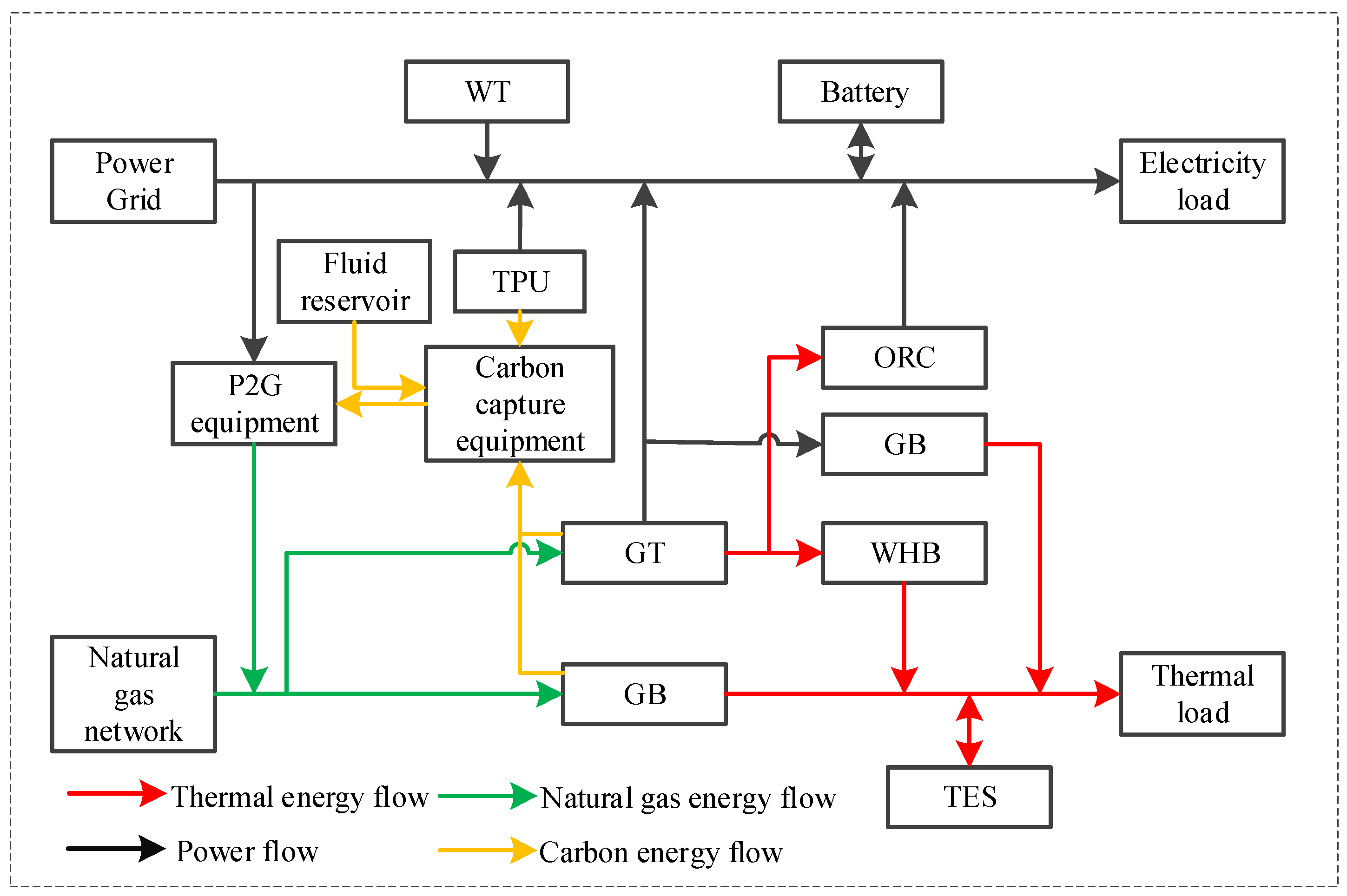
2. The Structure of the MEM

A MEM is a comprehensive energy supply system that integrates different forms of energy, such as cold, heat, electricity, and gas. Thermal power units, wind turbines, and gas turbines are the system’s core power supplies, and it relies on diversified energy conversion devices and energy storage facilities to organically integrate traditional fossil energy (coal, natural gas, oil) with renewable energy. By constructing a chain of the mechanisms involved in the coordination of energy production, conversion, storage, and consumption, the integrated production and consumption of energy can be realized. When there is an energy gap in the system, it can be dynamically compensated for through cross-energy flow conversion technologies (power-to-gas or combined cooling, heating and power, etc.) to enable the efficient complementarity and flexible substitution of various forms of energy.
Our proposed MEM architecture, containing a CCPP and CHP and P2G devices, is shown in Figure 1. The power supply side of the system includes a thermal power unit (TPU), wind turbine (WT), gas turbine (GT), organic Rankine cycle (ORC) system, electric energy storage (EES), and power grid purchase. The thermal power supply side includes an electric boiler (EB), waste heat boiler (WHB), gas boiler (GB), and thermal energy storage (TES) and realizes the coupling of electricity and gas energy and the utilization of carbon dioxide through the P2G device.
The improved CHP flexible output model uses the GT, EB, ORC, and WHB, and the CCPP flexible operation model uses the coal-fired units and carbon.

3. Mathematical Modeling of the MEM

3.1. Model of Carbon Capture Power Plant

As the high levels of carbon emissions generated by coal-fired units during peak electric load periods leads to a surge in carbon capture energy consumption, traditional CCPPs experience a technical bottleneck in the coordinated operation of their of carbon capture and power supply systems. This study proposes adding a bypass valve and a rich–lean-liquid double storage tank system to the CCPP flue gas treatment system. By dynamically adjusting the solution circulating from the rich–lean liquid storage tank, the space–time translation of the energy consumed during carbon capture can be realized, and a new flexible operation mode can be constructed. This leads to the dynamic decoupling of carbon dioxide capture and the unit’s power generation by independently controlling the circulation of the solution in the absorption tower and the regeneration tower. Specifically, during peak load periods, part of the rich liquid is temporarily stored in the storage tank, which reduces the energy required for real-time capture, ensuring efficient power generation; during low-load periods, the low-grade heat released by the energy storage tank is used to complete the solution’s regeneration, balancing the demands of carbon capture and power supply across the full cycle. This can be expressed as follows:
t = 1 T P CCPP t = t = 1 T ( P Jin t + P Yun t + P Gu t ) E CCPP = ε G t = 1 T P CCPP t E CO 2 IN = ε B η B E CCPP + E CO 2 cyc 0 ε B ε B , max 0 t P Yun t d t = δ B 0 t E CO 2 IN d t E J = E CCPP ε B η B E CCPP
where T is the scheduling period; ε G and P CCPP t are the carbon emission intensity and total output power of the CCPP, respectively; ε B and ε B , max are the efficiency of carbon capture and the maximum efficiency of carbon capture, respectively; δ B is the energy consumed per unit of CO2 captured by the CCPP; P Jin t is the net output power of the CCPP; E CO 2 cyc is the total mass of CO2 to be treated by the liquid storage tank; P Gu t is the fixed energy consumption of the CCPP; E CO 2 IN is the total mass of CO2 to be treated in the CCPP desorption tower; η B is the flue gas split ratio; and E J is the net carbon emissions of the CCPP.
By introducing the lean–rich-liquid storage tank system into the CCPP, the plant can realize the space–time decoupling of the absorption and regeneration processes by dynamically adjusting the solution’s circulation. Specifically, during peak load periods, the rich liquid is temporarily stored in the liquid storage tank, which reduces the energy required for real-time carbon capture to ensure efficient power generation; the solution’s regeneration is completed using the low-grade thermal energy released by the energy storage tank during low-load periods. This time-sharing mechanism separates the operating cycles of the absorption tower and the regeneration tower from each other, resolves the coupling limitation seen in traditional CCPPs, and provides greater operational flexibility for the system. The mathematical model of the liquid storage tank can be expressed as follows:
C rich t = ρ CO 2 L rich t L rich t + L poor t = 0 S rich t = S rich t 1 L rich t S poor t = S poor t 1 L poor t
where S rich t and S poor t are the liquid storage capacity of the lean and rich liquid storage tanks, respectively; ρ CO 2 is the density of the CO2 solution in the rich liquid tank; and L rich t and L poor t are the solution outflow/inflow of the lean and rich liquid storage tanks, respectively.
The liquid storage tank needs to meet the following constraints:
S rich 0 = S rich T S poor 0 = S poor T 0 S rich t S rich max 0 S poor t S poor max
where T is the scheduling period; S rich 0 / S poor 0 and S rich T / S poor T are the liquid storage capacity of the rich/lean liquid storage tanks at the beginning and end of the scheduling cycle, respectively; and S rich max and S poor max are the maximum liquid storage volume of the rich/lean liquid storage tanks, respectively.

3.2. Flexible Output Model of CHP Unit

A traditional CHP unit is composed of a GT and waste heat boiler (WHB). As the core energy supply unit of integrated energy systems, GTs use natural gas as their main fuel, which has significant advantages over coal: their power generation efficiency can reach 35–42%, their nitrogen oxide emissions are less than 50 mg /m3, and they are able to start and stop quickly (start-up time ≤ 10 min). As a key piece of equipment in energy cascades, WHBs convert high-temperature flue gas (450–600 °C) generated during power generation in gas turbines into medium-pressure steam of 0.8–1.6 MPa to meet regional heating needs. GT and WHB models can be formulated as follows:
P GT , e t = η GT , e P GT , g t P GT , h t = η GT , h P GT , g t P WHB _ h t = η WHB P GT , h t
where P GT , g t is the natural gas consumed by the GT; P GT , e t and P GT , h t are the electrical and thermal power of the GT’s output, respectively; P WHB _ h t is the thermal power output by the WHB; η GT , e and η GT , h are the electrical and thermal conversion efficiency of the GT, respectively; and η WHB is the conversion efficiency of the WHB.
As the key piece of equipment involved in electro-thermal coupling, an electric boiler (EB) usually converts excess power from the power grid into stored sensible or latent heat during the periods where electricity prices are low. This allows it to supplement load gaps in the heating network. It adopts resistive heating technology with millisecond response times and a modular design, which effectively improves the efficiency of electro-thermal conversion. The ORC is a thermodynamic cycle system that uses mixed refrigerants. It uses a mixed solution of ammonia and water (at a mass ratio of about 70:30) as its working medium and achieves the efficient recovery of low-grade waste heat through the unique phase separation characteristics of these fluids. Models of the WHB, EB, and ORC can be expressed as
P WHB , h t = η WHB P WHB t P EB , h t = η EB P EB t P ORC , e t = η ORC P ORC , h t
where P WHB t is the WHB’s thermal power; P ORC , h t and P ORC , e t are the thermal and electrical power of the ORC; P EB , h t and P EB t are the thermal and electrical power of the EB; and η EB and η ORC are the conversion efficiency of the EB and ORC.
Therefore, the electrical energy output from the GT can flow to the EB and supplement its electrical load, while the thermal energy output from the GT can flow to the WHB and ORC. The GT’s mathematical model can be expressed as follows:
P GT , e t = P EB t + P GT _ Grid t P GT , h t = P WHB t + P ORC , h t
where P GT _ Grid t is the electric power required to be input into the GT’s power system.
Therefore, the improved CHP flexible output model can be expressed as
P CHP , e t = P GT _ Net t + P ORC , e t P CHP , h t = P WHB , h t + P EB , h t
where P CHP , e t and P CHP , h t are the electric and thermal output powers of CHP, respectively.

3.3. P2G Operation Model

Power-to-gas (P2G) equipment is used to convert substances such as water or carbon dioxide into gas fuels that can be stored or utilized through the creation of electric energy. This equipment is mainly used for the consumption of renewable energy, peak shaving the power grid, and energy storage and its mathematical model is expressed as follows:
P P 2 G , g t = η P 2 G P P 2 G t
where P P 2 G t is the input power of the P2G unit; P P 2 G , g t is the output gas power of the P2G unit; and η P 2 G is the efficiency of the P2G unit in converting power to gas.

3.4. Gas Boiler Model

As the main source of heat in MEMs, GBs create heat by burning natural gas and are characterized as being highly efficient and environmentally friendly. The relationship between the output power of a GB and the gas input into it is
P GB t = η GB P GB , g t
where η GB is the GB’s thermal efficiency and P GB , g t is the amount of natural gas input into the GB.

3.5. Multi-Source Energy Storage Link Modeling

The energy storage equipment used in this paper includes a battery and a heat storage tank. The charging and discharging models of each piece of equipment can be expressed in terms of the following constraints:
(1)
Energy storage state constraints
The energy storage capacity of energy storage device x and the satisfaction of its constraint are as follows:
S t x = S t 1 x ( 1 γ x ) + ( P t x , chr η x , chr P t x , dis / η x , dis ) S min x S t x S max x S 24 x = S 1 x
where S min x and S max x are the minimum and maximum capacity of energy storage equipment x, respectively; γ x is the rate at which energy is lost from the energy storage equipment; S 24 x and S 1 x are the energy storage capacity of the equipment at the beginning and end of its use, respectively; and η x , chr and η x , dis are the charging and discharging efficiency of energy storage equipment x, respectively.
(2)
Energy charging and discharging state constraints
I t x , chr + I t x , dis 1 t = 1 24 ( I t BT . dis + I t BT . chr ) T
where I t x , chr and I t x , dis are the mark bits of the charging and discharging states of the energy storage equipment, respectively, and T is the total amount of energy charged and discharged.
(3)
Output constraints and climbing rate constraints
P min x , chr P t x , chr P max x , chr P min x , dis P t x , dis P max x , dis P down x , chr P t x , chr P t 1 x , chr P up x , chr P down x , dis P t x , dis P t 1 x , dis P up x , dis
where P t x , chr and P t x , dis are the charging and discharging power of the energy storage device x, respectively, and P t x , dis / P min x , dis and P max x , chr / P max x , dis are the minimum and maximum values of the charging/discharging power of the energy storage device x, respectively. P up x , chr / P up x , dis and P down x , chr / P down x , dis are the upper and lower limits of the climbing rate of the energy storage equipment x during charging/discharging, respectively.

4. Low-Carbon Scheduling Model of Flexible Carbon Capture-CHP-P2G MEM

4.1. Mechanism of Combined Flexible Operation of Carbon Capture-CHP-P2G MEM

Figure 2 presents a diagram of the framework required for the flexible operation of a carbon capture-CHP-P2G MEM. In this paper, a model of this microgrid is constructed by combining CCPP and CHP flexible operation models with the operating characteristics of P2G equipment. The traditional CHP system is limited to either “determining electricity by heat” or “determining heat by electricity”, and its electric heat output struggles to match the demand for power during peaks and valleys in power production, which leads to the problem of wind curtailment when wind power is generated at night. CCPPs are low-carbon systems created by installing carbon capture devices within traditional coal-fired units. Carbon capture devices can capture the CO2 emitted by coal-fired power plants and sequester it for long-term storage or resource utilization, thereby reducing the system’s carbon emissions. However, during peak periods, the increase in carbon emissions from coal-fired units will increase the energy consumed by the CCPP system to capture this carbon, resulting in a decrease in its net output power. This makes it difficult to balance carbon capture and the demand for power and may cause the abandonment of wind resources. By introducing a liquid storage tank into the CCPP system, the solution reserves in the regeneration tower and the absorption tower can be adjusted, and the CCPP can operate flexibly because of the decoupling of the CO2 absorption and capture processes, thereby alleviating the problems caused by peak–valley differences in power and thermal load. This effectively improves the adaptability of CCPPs in load fluctuation scenarios and provides a feasible solution for both carbon capture and the power supply.
This flexibility can effectively stabilize peak–valley fluctuations in load and improve the system’s capacity to consume renewable energy. However, the system may still abandon attempts to consume energy produced using wind and light resources to a certain degree due to the operational constraints of its equipment. The results show that although our flexible joint operation strategy can optimize the matching of energy supply and demand, in the scenario of an extreme surplus of renewable energy, the physical limitations of the equipment and operational rules will still lead to some clean energy not being fully consumed, which highlights the importance of building a multi-energy system and improving the equipment’s flexibility.
The EB can be used to convert the electric power generated from peak loads at night into heat energy, effectively absorbing surplus wind power. In the CCPP system, the liquid storage tank can transfer the CO2 generated during peak periods of electricity consumption to this period for capture and increase the energy consumed during carbon capture by reducing the net output of the CCPP. When a period of peak power consumption is experienced but there is a low heat load, the ORC equipment starts to operate. By converting part of the heat energy produced into electric energy, this equipment not only relieves the pressure on the power supply but also reduces the energy consumed for carbon capture in this period, thus improving the net output power of the CCPP during peak power consumption periods. This technical scheme realizes the dynamic optimization of power, heat, and carbon capture processes through the coordination of multiple systems and effectively solves the problem of mismatches between supply and demand seen in traditional energy systems.
In addition, by integrating the CCPP and CHP systems, the CO2 produced during the operation of coal-fired units and CHP units can be captured and used as a raw material for the P2G system. This synergy not only reduces the amount of external CO2 purchased by the system but also reduces the cost of storing CO2 and realizes the efficient recycling and economic improvement of carbon resources.

4.2. Combined Flexible Operation of Carbon Capture-CHP-P2G Model

In the model’s joint operation mode, the raw carbon materials required by the P2G unit can be obtained from the CCPP, CHP, and additional purchases. This is expressed as follows:
C P 2 G = C CCPP + C CHP + C Buy C P 2 G = δ CO 2 P P 2 G t
where C P 2 G is the total amount of raw carbon material required for P2G conversion; C Buy is the raw carbon materials purchased; C CCPP and C CHP are the amounts of carbon dioxide provided during the operation of the CCPP and CHP, respectively; and δ CO 2 is the mass of CO2 required for P2G conversion to consume 1 MWh of electric energy.
Therefore, the amount of carbon dioxide stored by the CCPP can be expressed as
C FCO 2 = ( ε B η B E CCPP + E CO 2 cyc ) C P 2 G
where C FCO 2 is the amount of carbon dioxide trapped by the power plant.
Because the methanation reaction occurring in P2G systems is exothermic, when optimizing the joint operation of multiple systems, the energy consumed by carbon capture equipment can be reduced by making use CCPP waste heat, the heat released from the P2G methanation reaction, and heat produced by the CHP system. This heat coupling effectively realizes the cascade utilization of energy flow, reduces the demand for external energy inputs, and improves the overall energy efficiency of the system:
P CCPP t + P P 2 G , H t + P CHP - CCPP t = P Yun t + P Gu t P P 2 G , H t = α p G CH 4 t
where P P 2 G , H t is the heat generated by the methanation reaction used in P2G equipment; P CCPP t is the total energy consumed by the carbon capture equipment; P CHP - CCPP t is the heat supplied by the CHP to the CCPP; G CH 4 t is the amount of CH4 generated; and α p is the heat generated by converting CO2 to CH4.
It can be seen from the methanation reaction that the volume of CO2 consumed by the P2G system is equal to the volume of CH4 generated; that is,
C P 2 G = ρ CO 2 V CO 2 = ρ CO 2 V CH 4 V CH 4 = 3.6 η P 2 G P P 2 G , g t Q g , L H V
where η P 2 G is the efficiency of P2G conversion; ρ CO 2 is the density of CO2; V CO 2 and V CH 4 are the volume of CO2 consumed and CH4 generated by P2G, respectively; and Q g , L H V is low calorific value of natural gas.

4.3. MEM Low-Carbon Scheduling Model

The low-carbon economic dispatch model of a MEM aims to find the minimum cost of running the system and comprehensively considers the system’s carbon transaction cost F CET , outsourcing cost F Buy , unit operation and maintenance cost F m , abandoned wind cost F WT , CCPP operation cost   F CCPP , and coal consumption cost of its thermal power units F coal . The objective function used for this is
min   F IES = F CET + F m + F Buy + F WT + F coal + F CCPP
The outsourcing cost includes the cost of electricity and gas purchases and is expressed as follows:
F Buy = t = 1 T α e t P Grid _ e t + t = 1 T α g t ( P CHP , g t + P GB , g t Q g , L H V )
where α e t and α g t are the price of the electricity and gas purchased from the MEM, respectively, and P Grid _ e t is the amount purchased by the MEM.
The cost of equipment operation and maintenance is
F m = t = 1 T ( i λ i P i t + j γ j ( P j , c t + P j , d t ) )
where i and j are the energy conversion equipment and energy storage equipment used, respectively; P i t is the output power of energy conversion equipment i; P j , c t and P j , d t are the charging and discharging power of energy storage device j, respectively; and λ i and γ j are the operation and maintenance coefficients of energy conversion equipment i and energy storage equipment j.
The CCPP’s operating cost F CCE includes the cost of operating and maintaining its carbon capture equipment f cce , the cost of storing carbon dioxide f store , and the cost of solution losses f RY and is expressed as follows:
F CCE = f cce + f store + f RY f cce = c ZJ ( 1 + λ ) n ZJ λ 365 [ ( 1 + λ ) n ZJ 1 ] + R RY V RY ( 1 + λ ) n RY λ 365 [ ( 1 + λ ) n RY 1 ] f store t = 1 T δ store ( ε B λ B ( E MEA , c t + ε B δ B E CCPP t ) λ P 2 G P P 2 G t ) f RY = t = 1 T α L k L ( E MEA , c t + ε B δ B E CCPP t )
where c ZJ and n ZJ are the total cost of the carbon capture equipment and its depreciation period, respectively; E CCPP t is the CO2 emissions generated by the CCPP at time t; α L is the loss coefficient of the liquid storage tank; λ P 2 G is the P2G unit’s carbon capture coefficient; λ is the carbon capture discount rate; E MEA , c t is the amount of CO2 to be captured that is supplied by the liquid storage tank at time t; n RY is the depreciation period of the liquid storage tank; R RY is the total cost of the liquid storage tank per unit volume; V RY is the volume of liquid storage tank j; δ store is the storage cost coefficient of a unit of CO2; and k L is the operating coefficient of the liquid storage tank.
The cost of wind curtailment is
F WT = t = 1 T δ WT ( P WT , 0 t P WT t )
where δ WT is the coefficient of the penalty for wind power abandonment and P WT , 0 t and P WT t are the predicted and actual wind power output.
In this paper, carbon quotas were allocated by means of free allocation. The sources of carbon emissions in a MEM mainly include CHP, the GB, the CCPP, and external power purchases (assuming that the external power purchased is from coal-fired power plants). With these carbon emission sources in mind, the baseline method is used to carry out the allocation of carbon quotas. In a MEM, the carbon emissions generated by CHP, the GB, the CCPP, and purchased electricity can be expressed as a quadratic function. In addition, the P2G unit has the ability to absorb part of the CO2 generated. The CO2 emitted after the CCPP treatment can be preferentially used as the raw reaction material for P2G conversion, which not only promotes the recycling of carbon but also reduces the cost of carbon sequestration. The actual carbon emissions of a MEM can be expressed as follows:
E gas act = t = 1 T ( x 2 ( P gas t ) 2 + y 2 P gas t + z 2 ) P gas t = φ e - h P CHP , e t + P GB , h t + P CHP , h t E Net _ e act = t = 1 T ( x 1 ( P Net _ e t ) 2 + y 1 P Net _ e t + z 1 ) E CCPP act = t = 1 T ( x 1 ( P CCPP , e t ) 2 + y 1 P CCPP , e t + z 1 ) E P 2 G = t = 1 T λ P 2 G P P 2 G t E IES act = E gas act + E Net _ e act + E CCPP act E P 2 G
where x 1 , y 1 , and z 1 are the carbon emission coefficients of the MEM’s coal-fired units; E Net _ e act and E CCPP act are the actual carbon emissions from the purchased electricity and CCPP, respectively; x 2 , y 2 , and z 2 are the carbon emission coefficients of the gas turbine; E gas act is the actual carbon emissions of CHP and the GB in the MEM; P gas t is the equivalent output power of CHP and the GB; E IES act is the total actual carbon emissions of the MEM; λ P 2 G is the P2G unit’s carbon capture coefficient; P P 2 G t is the electrical power consumed by the P2G unit; and E P 2 G is the amount of carbon dioxide absorbed by P2G conversion.
The carbon transaction cost borne by the MEM can be expressed as
F CET = c CET ( E IES act E IES )
where E IES act is the total carbon emissions of the MEM, E IES is its initial carbon emission quota, and c CET is the carbon transaction cost.
The coal consumption cost of the thermal power units is
F coal = t = 1 T n = 1 N a n ( P G t , n ) 2 + b n P G t , n + c n + U G t , n ( 1 U G t 1 , n ) δ G n
where N is the total number of thermal power units; a n , b n , and c n are the burnup cost coefficients of the coal-fired unit n; U G t , n is the operating state of coal-fired unit n; and δ G n is the start–stop cost coefficient of coal-fired unit n.

4.4. Constraints

(1)
Interactive power constraints
0 P Grid _ e t P Grid _ e max 0 P Net _ g t P Net _ g max
where P Net _ g t is the superior gas purchasing power of the MEM and P Net _ e max and P Net _ g max are the upper limit of its power purchases and gas purchases, respectively.
(2)
Operation constraints of thermal power units
0 P G t P G max P G down P G t P G t 1 P G up
where P G max is the upper limit of P G t and P G up and P G down are the upper and lower limits of the climbing rate P G t , respectively.
(3)
Power balance constraints
P CCPP , e t + P WT t + P CHP , e t + P BT , d t + P Net _ e t + P GT _ Grid t + P ORC , e t = L e t + P BT , c t P GB , h t + P TST , d t + P CHP , h t + P EB , h t = L h t + P TST , c t P GT , g t + P GB , g t = P Net _ g t + P P 2 G , g t
where L e t and L h t are the user’s electrical load and thermal load, respectively.

5. Case Analysis

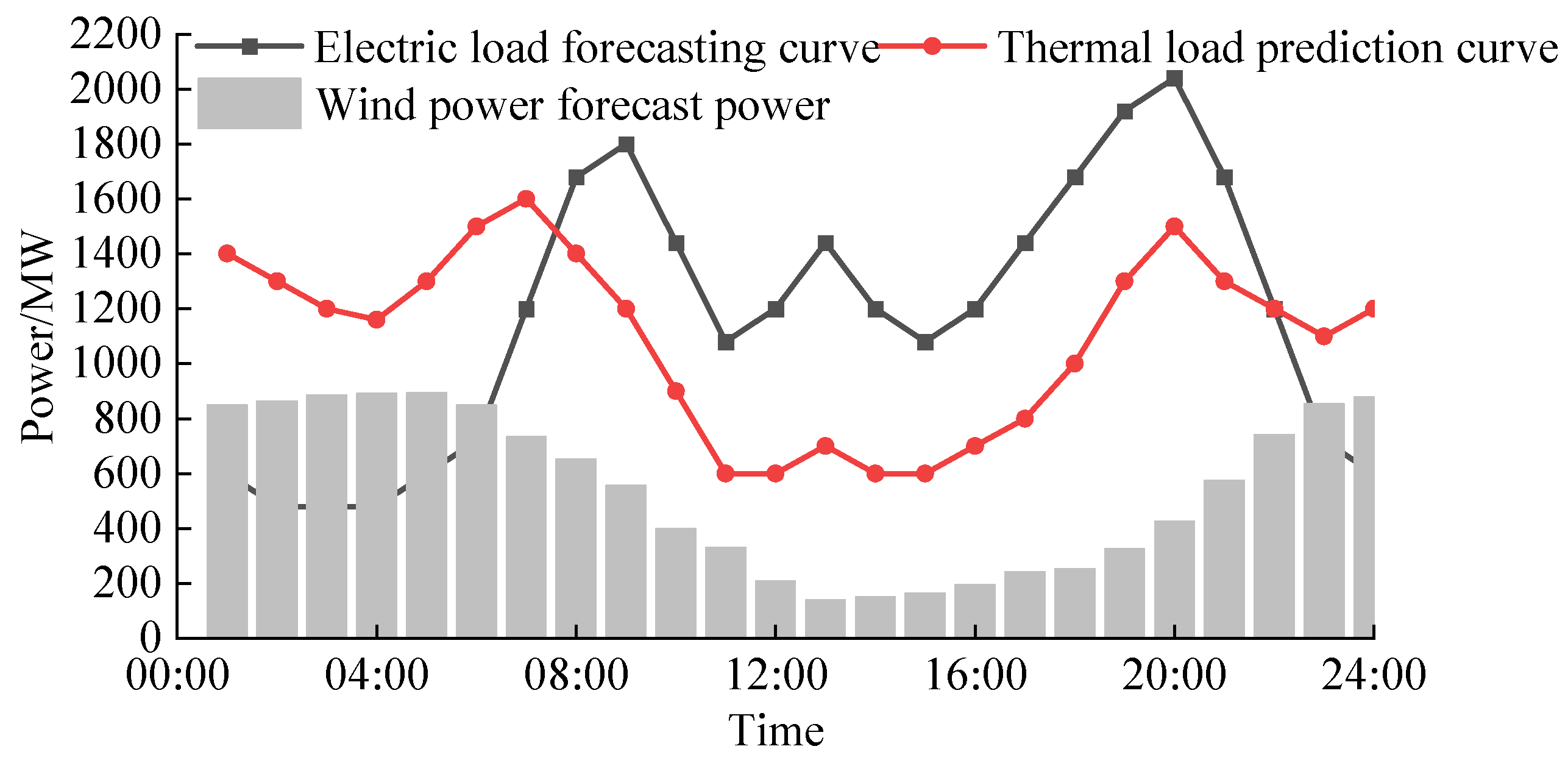
5.1. Basic Parameters

In this paper, T = 24 h is used as the scheduling cycle for in a simulation used to verify the effectiveness of our low-carbon optimal scheduling model for a flexible carbon capture-CHP-P2G MEM. The system’s time-of-use electricity prices are shown in Table A1, while the structure of the MEM is shown in Figure 1. Prediction curves of the system’s electricity and heat loads and the available wind power are shown in Figure 3 [25]. The parameters of the MEM equipment are shown in Table A2. Carbon capture-related parameters are shown in Table A3; the unit carbon trading price, cCET, is 0.268 CNY/kg; the carbon emission coefficients x1, y1, and z1 of the coal-fired units are 36, −0.38, and 0.0034, respectively, and the carbon emission coefficients x2, y2, and z2 of the gas-fired units are 3, −0.04, and 0.001, respectively. The low-carbon scheduling model for MEMs proposed in this paper is solved using the Yalmip modeling method and the commercial solver GUROBI, which is based on the MATLAB R2018 b platform, in an Intel Core i7-8750 CPU computing environment with 16.0 GB of memory.

5.2. Validation of the Effectiveness of the Combined Flexible Operation of the Carbon Capture-CHP-P2G MEM
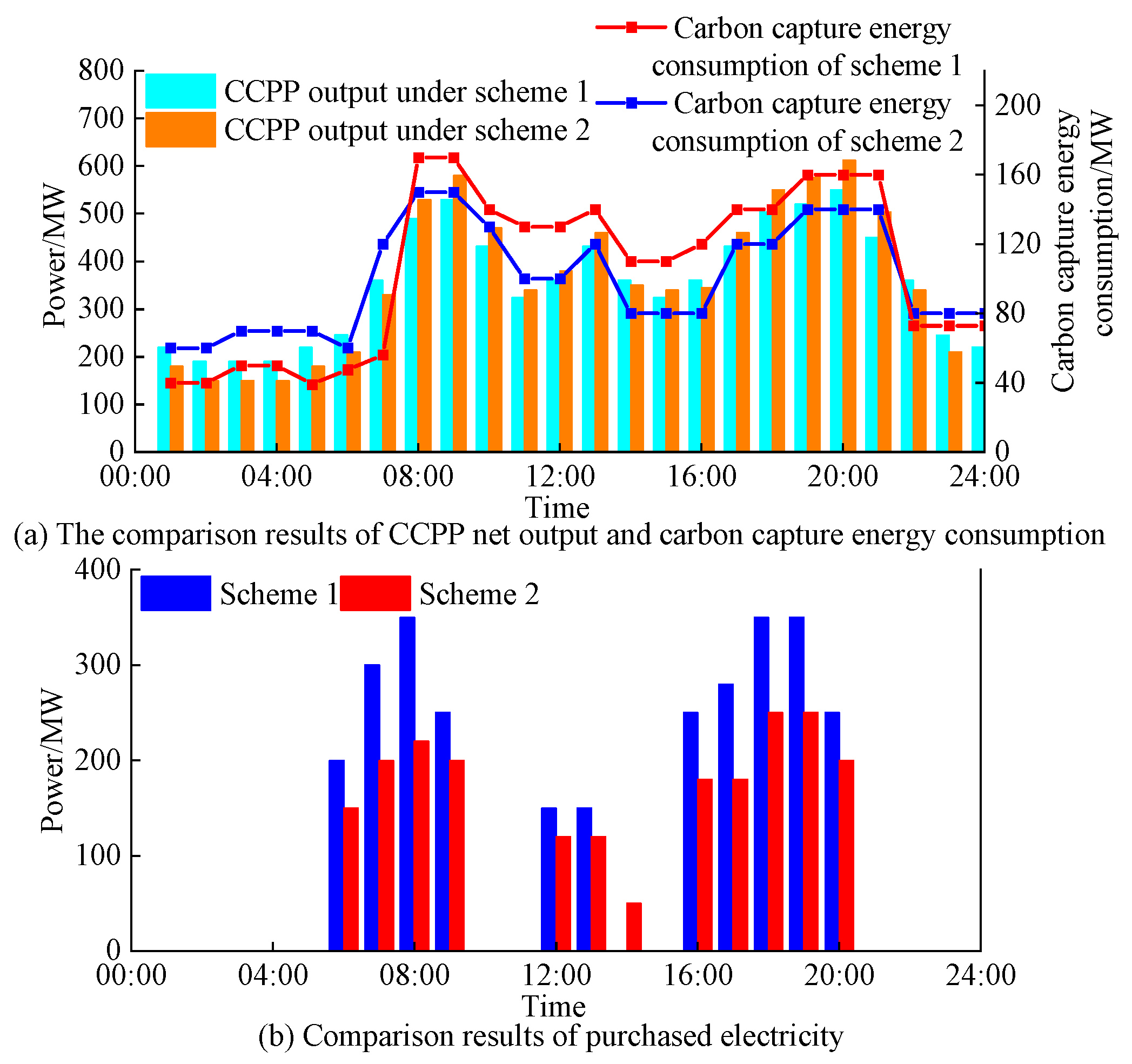
In order to verify the effectiveness of our carbon capture-CHP-P2G MEM model and its economic and environmental benefits, the following five schemes were established.
Scheme 1: the traditional MEM scheduling model, with the CCPP participating in its shunt operation mode;
Scheme 2: the same as Scheme 1, but with a liquid storage tank introduced to form a flexible CCPP operation model;
Scheme 3: the same as Scheme 1, but with the EB model introduced;
Scheme 4: the same as Scheme 3, but with the ORC model introduced to enable the flexible operation of CHP;
Scheme 5: the joint flexible carbon capture-CHP-P2G MEM model proposed in this article.
The results of a cost comparison of the five schemes are shown in Table 1.
(1)
Analysis of flexible CCPP operation model
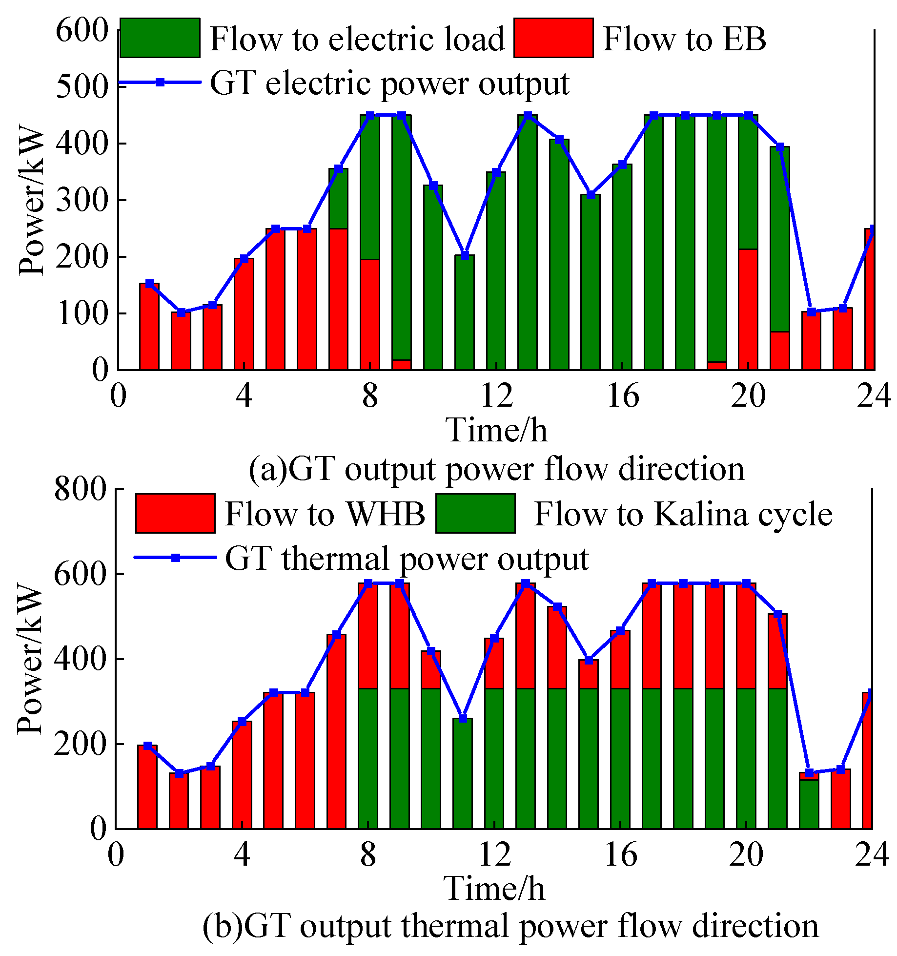
In order to verify the effectiveness of the flexible CCPP operation model, Schemes 1 and 2 were compared and analyzed. Figure 4 shows the operational results of the CCPP and the electricity purchased under the two schemes.
As shown in Figure 4a, the two schemes are significantly different in their CCPP operating characteristics, outsourced electricity, and energy consumed for carbon capture. When the CCPP’s split operation mode is adopted in Scheme 1, the carbon capture equipment captures the carbon dioxide generated by the thermal power unit; however, there are problems with the low level of carbon captured and large amounts of energy consumed to generate that capture during peak load periods, which leads to an increase in the CCPP’s net output and the level of power outsourcing required, increasing the cost of coal combustion. Therefore, the net output of the split-mode CCPP during peak load periods is significantly lower than that of the CCPP in Scheme 2. Unlike Scheme 1, Scheme 2 constructs a comprehensive and flexible operation mode for the CCPP by adding a liquid storage tank. In this scheme, the liquid storage tank allows the unit to absorb all the CO2 created during peak load periods without capturing it, thereby reducing the energy consumed for carbon capture during these periods, increasing the net output of the CCPP, and reducing the demand for purchased electricity. During valley load periods, the liquid storage tank releases the CO2 generated during peak load periods for capture. Although this will reduce the net output of the CCPP, it can increase the energy consumed during carbon capture and enhance the system’s wind power consumption capacity during valley load periods. As shown in Figure 4b, the energy consumption for carbon capture in Scheme 2 shows obvious ‘peak load shifting’ characteristics: the energy consumed during peak load periods decreases, while the energy consumed during valley load periods increases. In addition, the scale of the electricity outsourced by the MEM in Scheme 2 is significantly reduced, which simultaneously reduces its carbon emissions. It is worth noting that the CCPP’s flexible operation mode enables the P2G system to flexibly obtain the CO2 captured by the CCPP through its CO2 transfer mechanism. This not only reduces the total carbon emissions of the system but also significantly reduces the cost of carbon sequestration and transportation, leading to comprehensive benefits.
According to the data in Table 1, when compared with Scheme 1, the cost of abandoned wind power and the MEM’s total cost in Scheme 2 are reduced by 24.70% and 4.04%, respectively. The carbon emissions of the system are also reduced by 8.49%, which fully confirms the effectiveness of the CCPP’s flexible operation mode. When combined with the analysis in Figure 4, the net output of the CCPP in Scheme 2 is significantly improved during peak electric load periods compared to that in Scheme 1, which effectively reduces the amount of electricity purchased during these periods. The energy consumed for carbon capture shows obvious peak-shaving and valley-filling characteristics in Scheme 2 as well. Although the net output of the CCPP is higher during peak load periods in Scheme 1, due to the CCPP’s split operation mode in this scheme, the energy consumed for carbon capture increases significantly with the large amount of CO2 produced, which eventually leads to a decrease in the net output of the carbon capture units and an increase in purchased electricity.
(2)
Analysis of the validity of the CHP flexible operation model
Next, Schemes 1, 3, and 4 are compared. Scheme 3 introduces the EB model, which can convert all the GT power output in the 23:00–07:00 period into heat, removing the limitation of this equipment “determining heat by power”. According to the calculations in Table 1, when compared with Scheme 1, the abandoned wind cost, total MEM cost, and carbon emissions of Scheme 3 are decreased by 19.82%, 3.71%, and 3.19%, respectively, verifying the effectiveness of the proposed EB model. Although the amount of wind power consumed during this period was effectively increased, it was still limited by the GT “determining power by heat”.
Scheme 4 optimizes the system’s operation by combining the ORC model and the EB model. As shown in Figure 5, the electric and thermal power flows of the GT in Scheme 4 show significant time-sensitive characteristics: in the nighttime periods of 22:00–24:00 and 01:00–06:00, all the electric power from the GT is directed to the EB for heat production due to the high wind power output; this improves the system’s capacity to consume wind power. In the peak period of 09:00–19:00, because of the high power load and high price of electricity, the GT inputs part of its heat output into the Kalina cycle for power generation, thus reducing the power purchased by MEM from the external power grid during this peak period. According to the data in Table 1, compared to Scheme 3, the abandoned wind cost, total MEM cost, and carbon emissions of Scheme 4 are reduced by 16.92%, 4.59%, and 4.26%, respectively, which verifies the effectiveness of the CHP flexible demand–response model. In addition, as shown in Figure 6, the BT and TST energy storage devices further enable peak load shifting in the system and optimize its overall energy utilization efficiency by charging heat storage devices during low-load periods and discharging them during peak periods.
(3)
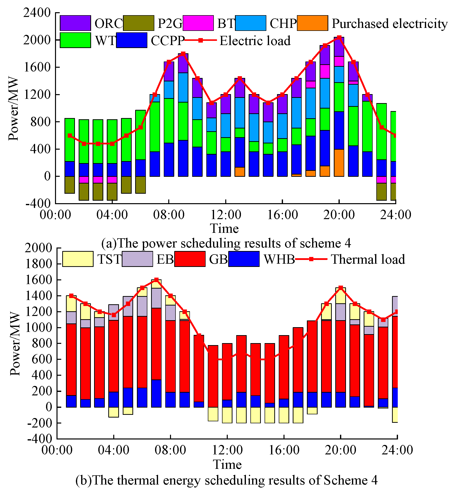
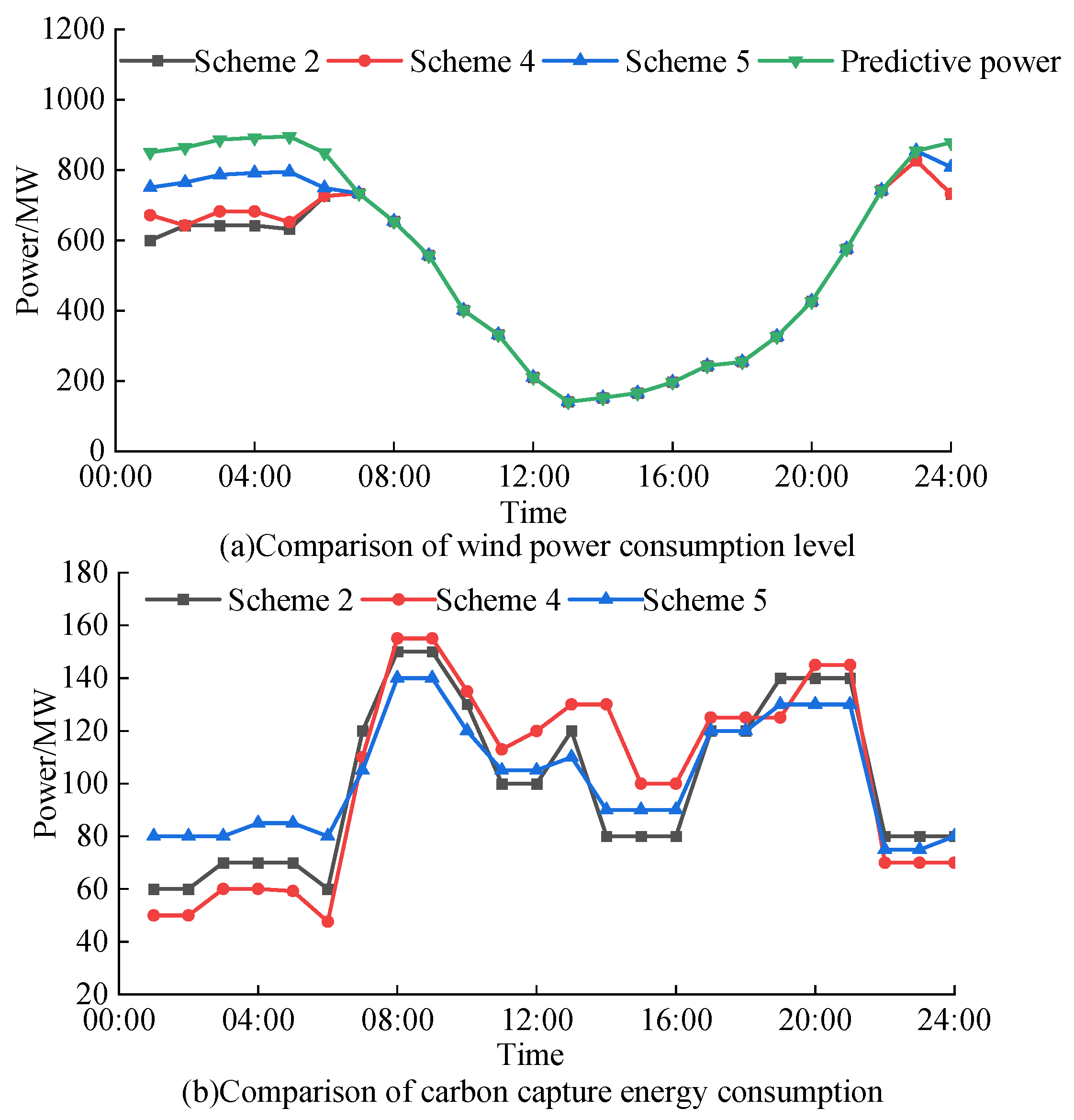
Validation of the joint flexible carbon capture-CHP-P2G MEM model
In order to verify the effectiveness of the joint flexible CCPP-P2G-CHP MEM model proposed in this paper, Scheme 5 was compared with Schemes 2 and 4. Figure 7 shows the results of comparing their wind power consumption level and energy consumed for carbon capture.
Scheme 5 considers both flexible CCPP operation and flexible CHP operation, forming a joint carbon capture-CHP-P2G joint model. During the nighttime, through the power-to-heat function of the EB, the output power of the GT is converted into heat, which can alleviate the demand for heat at night. At the same time, because of the time shift in carbon capture enabled by the liquid storage tank, the carbon capture required at periods of peak electricity consumption is transferred to the night, which reduces the net output of the CCPP, improves the energy consumed for carbon capture, and further increases the consumption of wind power. From Figure 2a–Figure 7a and the data in Table 1, it can be seen that the wind abandonment cost of Scheme 5 is 30.4% and 14.15% lower than that of Schemes 2 and 3. In addition, due to the increase in the level of wind power consumed, the system’s green card trading income increases, which reduces the total cost of the system. During peak periods of electricity consumption, where there is a low demand for heating, the MEM system not only reduces the energy consumed for carbon capture by means of liquid storage tanks but also converts part of the thermal power produced into electrical energy through the ORC, thereby increasing the net output of the CCPP and ultimately reducing the amount of electricity purchase during peak periods. Therefore, when both flexible CCPP operation and flexible CHP operation are considered, the system’s economy and carbon emissions can be significantly improved because of the combined advantages of consuming new energy consumption and transferring energy between parts of the system. Compared to Schemes 2 and 4, the total cost of Scheme 5 is decreased by 8.75% and 4.87%, respectively, and its carbon emissions are decreased by 16.49% and 9.89%, respectively.

6. Conclusions

In order to enhance the operational flexibility and low-carbon characteristics of traditional MEMs, this paper constructs a low-carbon and economic operation model for MEMs that optimizes the combined operation of a carbon capture power plant, CHP, and P2G unit. By introducing a liquid storage tank and EB and ORC models, the traditional CCPP and CHP systems are made more flexible: the liquid storage tank is combined with the CCPP to enable the dynamic regulation of the carbon capture process, and the EB and ORCs decouple the CHP’s ‘heat-to-electricity’ and ‘electricity-to-heat’ coupling modes. On this basis, a flexible carbon capture-CHP-P2G MEM model was proposed, and a low-carbon and economic scheduling model that integrates the coordination of multiple energy sources was established, with the goal of minimizing the total operating cost of a multi-energy microgrid system in a park.
The results of our simulations show that the introduction of the liquid storage tank enables the space–time translation of the energy consumed for carbon capture by dynamically adjusting the stock of the lean–rich solution in the liquid storage tank. While improving the operational flexibility of the CCPP and taking into account the demand for carbon capture and power supply, the total cost and carbon emissions of the MEM are reduced by 4.04% and 8.49%, respectively. The application of the EB and ORCs effectively alleviates the problem of peak–valley differences in electric heating load. In addition, the CO2 required by the P2G equipment can be derived from the coordinated operation of the CCPP and CHP, which further improves the energy efficiency of the system. Our joint operation model realizes the dual optimization of the MEM in terms of flexibility and low carbon emissions through the collaboration of multiple pieces of technology.
This paper only models a single regional multi-energy microgrid and ignores the additional cost of using energy conversion equipment and energy storage equipment, as well as the reduction in energy conversion efficiency caused by increased control complexity. In future research, the collaborative optimization of multi-energy microgrid systems that cover multiple regions and the decision-making made across regions could be analyzed and modeled, and the energy storage components and energy conversion equipment used could be modeled in a more refined manner.

Author Contributions

Conceptualization, X.W. and Y.X.; methodology, Y.L.; investigation, J.L.; writing, H.Z. All authors have read and agreed to the published version of the manuscript.

Funding

This research is funded by the Science and Technology Project of State Grid JiangSu Electric Power Company Limited (J2023103).

Data Availability Statement

The original contributions presented in this study are included in the article; further inquiries can be directed to the corresponding author.

Conflicts of Interest

Author Jie Li and Yafei Li were employed by the company State Grid Suzhou Power Supply Company, State Grid JiangSu Electric Power Company. The remaining authors declare that the research was conducted in the absence of any commercial or financial relationships that could be construed as a potential conflict of interest.

Appendix A

Table A1. Time-of-use electricity prices.
Price TimeCNY/kWh
Low1:00–6:00; 23:00–24:000.45
Time-of-use electricity pricesFlat13:00–17:000.75
Peak7:00–12:00; 18:00–22:001.20
On-grid price All day0.45
Table A2. MEM equipment operating parameters.
UnitCapacity/(MW)Conversion EfficiencyClimbing Rate Constraint/%Operational Cost/CNY
GT600Electricity: 0.40
Thermal power: 0.50
200.056
WHB8000.88200.035
GB9000.92200.03
EB2500.85200.032
ORC 3000.78200.06
P2G 3000.75200.088
Battery2000.92200.011
Heat storage tank2000.90200.016
Table A3. Carbon capture-related parameters.
ParameterValueParameterValue
λ CET 0.268 (CNY/t) P Gu 40 (MWh)
Q g , L H V 36 (MJ/m3) η B 1.2
δ B 0.269 (MWh/t) ε B , max 0.9
k L 0.9 δ store 30 (CNY/t)
λ P 2 G 600 (CNY/MWh) α L 0.92
S poor min 3000 m3 S rich max 60,000 m3

References

  1. Jin, C.; Ren, D.W.; Xiao, J.Y.; Hou, J.M.; Du, E.S.; Zhou, Y.B. Optimization Planning on Power System Supply-Grid-Storage Flexibility Resource for Supporting the “Carbon Neutrality” Target of China. Electr. Power. 2021, 54, 164–174. [Google Scholar]
  2. Wen, Y.; Qu, X.; Li, W.; Liu, X.; Ye, X. Synergistic Operation of Electricity and Natural Gas Networks via ADMM. IEEE Trans. Smart Grid. 2017, 9, 4555–4565. [Google Scholar] [CrossRef]
  3. Huang, G.; Liu, W.; Wen, F.; Dong, Z.; Zheng, Y.; Zhang, R. Collaborative Planning of Integrated Electricity and Natural Gas Energy Systems with Power-to-gas Stations. In Proceedings of the 2016 IEEE Innovative Smart Grid Technologies—Asia (ISGT-Asia), Melbourne, Australia, 28 November–1 December 2016; pp. 378–383. [Google Scholar]
  4. Xu, F.; Min, Y.; Chen, L.; Chen, Q.; Hu, W.; Zhang, W.; Wang, X.; Hou, Y. Combined Electricity-Heat Operation System Containing Large Capacity Thermal Energy Storage. Proc. CSEE. 2014, 34, 5063–5072. [Google Scholar]
  5. Zhang, M.; Xiao, P.; Yixin, H.; Zhifeng, G.; Weidong, L.; Junyou, Y. An Environmental Source-Load-Storage Economic Dispatch Model Considering Wind Power Accommodation. Renew. Energy Resour. 2019, 37, 1295–1302. [Google Scholar]
  6. Cui, Y.; Yang, Z.; Zhong, W.; Ye, X.H. A Joint Scheduling Strategy of CHP with Thermal Energy Storage and Wind Power to Reduce Sulfur and Nitrate Emission. Power Syst. Technol. 2018, 42, 1063–1070. [Google Scholar]
  7. Li, M.; Mu, H.; Li, N.; Ma, B. Optimal Design and Operation Strategy for Integrated Evaluation of CCHP (Combined Cooling Heating and Power) System. Energy 2016, 99, 202–220. [Google Scholar] [CrossRef]
  8. Liu, Y.M.; Wang, W.; Wang, X.D.; Peng, C. A Fuzzy Control Strategy Combined with Wind Power Prediction and Energy Storage SOE for Smoothing Wind Power Output. Power Syst. Technol. 2019, 43, 2535–2543. [Google Scholar]
  9. Lei, J.; Yu, L.; Guo, X.; Li, P.; Li, C.; Wu, Y. Planning Method for Integrated Energy System with the Consideration of Coupling among Power, Heat, and Gas. Proc. CSU-EPSA 2019, 31, 19–24. [Google Scholar]
  10. Chen, J.J.; Qi, B.X.; Rong, Z.K.; Peng, K.; Zhao, Y.L.; Zhang, X.H. Multi-energy Coordinated Microgrid Scheduling with Integrated Demand Response for Flexibility Improvement. Energy 2021, 217, 119387. [Google Scholar] [CrossRef]
  11. Guo, Z.; Li, G.Y.; Zhou, M.; Feng, W. Two-stage Robust Optimal Scheduling of Regional Integrated Energy System Considering Network Constraints and Uncertainties in Source and Load. Power Syst. Technol. 2019, 43, 3090–3100. [Google Scholar]
  12. Wei, Z.; Zhang, S.; Sun, G.; Xu, X.; Chen, S.; Chen, S. Carbon Trading Based Low-carbon Economic Operation for Integrated Electricity and Natural Gas Energy System. Autom. Electr. Power Syst. 2016, 40, 9–16. [Google Scholar]
  13. Qin, T.; Liu, H.; Wang, J.; Feng, Z.; Fang, W. Carbon Trading Based Low-carbon Economic Dispatch for Integrated Electricity-heat-gas Energy System. Autom. Electr. Power Syst. 2018, 42, 8–13. [Google Scholar]
  14. Zhang, Q.; Zhao, W.H.; Wang, H.Y. Optimized Scheduling of Multi-energy Cogeneration Distribution Networks Considering Hydrogen Blending Operation of Gas Equipment and Carbon Trading. Power Syst. Autom. 2024, 46, 24–27. [Google Scholar]
  15. Gao, Y.; Xu, Y.C.; Zhang, T.; Song, W.Y.; Wang, P.; Xi, L.; Mi, L. Multi-Microgrid System Optimization Scheduling Including Electric Vehicle Coordinated Charging and Reward and Punishment Ladder Carbon Trading. Electr. Power Constr. 2025, 46, 174–188. [Google Scholar]
  16. Chen, Z.; Hu, Z.; Weng, C.; Li, T. Multi-stage Planning of Park-level Integrated Energy System Based on Ladder-type Carbon Trading Mechanism. Electr. Power Autom. Equip. 2021, 41, 148–155. [Google Scholar]
  17. Wang, R.; Cheng, S.; Liu, Y.; Xu, J.; Li, M. Master-slave game optimal scheduling of energy hub based on integrated demand response and a reward and punishment ladder carbon trading mechanism. Power Syst. Prot. Control. 2022, 50, 75–85. [Google Scholar]
  18. Lu, S.; Lou, S.; Wu, Y.; Yin, X. Power System Economic Dispatch under Low-carbon Economy with Carbon Capture Plants Considered. IET Gener. Transm. Distrib. 2013, 7, 991–1001. [Google Scholar] [CrossRef]
  19. Zhou, R.; Xiao, J.; Tang, X.; Zheng, Q.; Lu, J.; Cao, J. Coordinated Optimization of Carbon Utilization between Power-to-gas Renewable Energy Accommodation and Carbon Capture Power Plant. Electr. Power Autom. Equip. 2018, 38, 61–67. [Google Scholar]
  20. Chen, B.D.; Lin, K.D.; Zhang, Y.J.; Chen, Z.X.; Wang, J.; Su, J.Y. Optimal Dispatching of Integrated Electricity and Natural Gas Energy Systems Considering the Coordination of Carbon Capture System and Power-to-Gas. South. Power Syst. Technol. 2019, 13, 9–17. [Google Scholar]
  21. Tian, F.; Jia, Y.; Ren, H.; Bai, Y.; Huang, T. Source-load Low-carbon Economic Dispatch of Integrated Energy System Considering Carbon Capture System. Dianwang Jishu 2020, 44, 3346–3354. [Google Scholar]
  22. Wang, H.; Hua, P.; Wu, X.; Zhang, R.; Granlund, K.; Li, J.; Lahdelma, R.; Teppo, E.; Yu, L. Heat-power Decoupling and Energy Saving of the CHP Unit with Heat Pump Based Waste Heat Recovery System. Energy 2022, 250, 123846. [Google Scholar] [CrossRef]
  23. Cui, Y.; Zeng, P.; Hui, X.; Li, H.; Zhao, J. Low-carbon Economic Dispatch Considering the Integrated Flexible Operation Mode of Carbon Capture Power Plant. Power Syst. Technol. 2021, 45, 1877–1886. [Google Scholar]
  24. Wang, Y.; Li, M.; Qi, Y. Low-carbon Economic Dispatching of Integrated Energy System with P2G Considering Comprehensive and Flexible Operation Mode of Carbon Capture Power Plant. Electr. Power Autom. Equip. 2023, 43, 1–8. [Google Scholar]
  25. Liu, Y.; Hu, Z.; Chen, J.; Weng, C.; Gao, M.; Liu, S. Low-carbon Economic Dispatch of Integrated Energy System Considering Carbon Capture Power Plant and Multi-utilization of Hydrogen Energy. Autom. Electr. Power Syst. 2024, 48, 31–40. [Google Scholar]
  26. Wang, J.; Ji, X.; Meng, X.; Bai, Y.; Li, M. Low-carbon economic dispatch of integrated energy system with carbon capture power plant and multiple utilization of hydrogen energy. Front. Energy Res. 2025, 12, 1447858. [Google Scholar] [CrossRef]
  27. Shang, Y.; Li, D.; Li, Y.; Li, S. Explainable spatiotemporal multi-task learning for electric vehicle charging demand prediction. Appl. Energy 2025, 384, 125460. [Google Scholar] [CrossRef]
  28. Li, X.; Hu, C.; Luo, S.; Lu, H.; Piao, Z.; Jing, L. Distributed Hybrid-Triggered Observer-Based Secondary Control of Multi-Bus DC Microgrids Over Directed Networks. IEEE Trans. Circuits Syst. I Regul. Pap. 2025, 72, 2467–2480. [Google Scholar] [CrossRef]
Figure 1. The structure of the MEM.
Energies 18 02905 g001
Figure 2. Schematic diagram of flexible operation of carbon capture-CHP-P2G system.
Energies 18 02905 g002
Figure 3. Prediction curves of electricity and heat loads and wind power available.
Energies 18 02905 g003
Figure 4. Comparison of CCPP’s operation and electricity purchased under different schemes.
Energies 18 02905 g004
Figure 5. The electric and thermal power flows of Scheme 4.
Energies 18 02905 g005
Figure 6. The electric and thermal energy scheduling balance of Scheme 4.
Energies 18 02905 g006
Figure 7. Comparison of the wind power consumed and energy consumed for carbon capture under different schemes.
Energies 18 02905 g007
Table 1. Results of cost comparison of Schemes 1–5.
Parameter/
Million CNY
Scheme 1Scheme 2Scheme 3Scheme 4Scheme 5
Coal cost73.5577.5971.3369.1871.52
Electricity purchasing cost15.3412.3913.5811.347.36
Natural gas purchasing cost166.27161.37162.33157.32151.34
Wind curtailment cost21.5816.2517.2614.3412.31
CET cost18.3314.2315.2212.369.55
Operational cost45.3248.3348.8849.2152.39
Carbon storage and transportation costs7.333.516.225.690
Total cost347.72333.67334.82319.44304.47
Total carbon emissions/ton7885.37215.66985.36687.36025.4
Disclaimer/Publisher’s Note: The statements, opinions and data contained in all publications are solely those of the individual author(s) and contributor(s) and not of MDPI and/or the editor(s). MDPI and/or the editor(s) disclaim responsibility for any injury to people or property resulting from any ideas, methods, instructions or products referred to in the content.

