Article

A Low Inrush Current Pre-Charging Strategy of M3C with Improved Nearest Level Modulation

1
Energy Storage Research Institute of Southern Power Grid Peak Shaving and Frequency Modulation Power Generation Co., Ltd., Guangzhou 511493, China
2
Shenzhen Hopewind Electric Co., Ltd., Shenzhen 518055, China
3
Department of Electrical Engineering, University of Shanghai for Science and Technology, Shanghai 200093, China
*
Author to whom correspondence should be addressed.
Energies 2025, 18(11), 2895; https://doi.org/10.3390/en18112895
Submission received: 18 April 2025 / Revised: 18 May 2025 / Accepted: 26 May 2025 / Published: 31 May 2025
(This article belongs to the Section F3: Power Electronics)

Abstract

The modular multilevel matrix converter (M3C) can perform AC/AC conversion directly. However, M3C operation often requires a pre-charging process, which can be challenging due to the need for fast pre-charging with low inrush current. To address the issue, a closed-loop fast pre-charging strategy is proposed that utilizes an improved nearest level modulation (NLM) based on a quick-sorting algorithm for M3C. By improving the current limiting resistor and the number of Sub-Modules (SMs) inserted into the NLM, we achieve a reduction in inrush current when connected to the grid, and unlock the control algorithm, respectively. This paper presents the relationship between the current-limiting resistor, the pre-charging current, and the pre-charging time. Reactive power compensation is applied on the AC grid during the pre-charging process to ensure stability. Furthermore, the balanced control of capacitor voltage is employed to achieve synchronized and coordinated growth of capacitor voltages in SMs using a quick-sorting algorithm based on NLM. The simulation and experimental results demonstrate the effectiveness of this approach, making it suitable for M3C with a high number of SMs.

1. Introduction

The Modular Multilevel Matrix Converter (M3C) enables direct AC-to-AC frequency conversion without requiring a DC-link, making it an attractive technology due to its modularity, scalability, reliability, and conversion efficiency [1]. Most studies on M3C assume that the initial SM capacitor voltages are at their rated value, whereas reaching the rated value usually requires a pre-charging stage [2,3,4]. This aspect is crucial, as SM capacitors in M3C start with zero voltage, and the system’s low equivalent impedance can lead to significant inrush currents, which could stress the IGBTs. Therefore, it becomes essential to charge all SM capacitor voltages in the bridge arms to their rated levels to ensure a safe and reliable charging process [5,6,7,8]. Unlike the Modular Multilevel Converter (MMC), the M3C is a three-input, three-output system that relies solely on the AC side for charging, and algorithms cannot control the IGBTs during the initial charging phase [9]. As a result, M3C pre-charging is divided into two stages: an uncontrolled pre-charging stage, where the system charges through the three-phase input line voltage, and a controlled pre-charging stage.
At the start of M3C pre-charging, the SM capacitors have zero voltage, and both the input and output of the SMs behave like a short circuit, causing significant inrush currents when a high voltage is applied to the bridge arm. To mitigate this, previous studies, such as [10] and [11], suggest using current-limiting resistors in series to reduce the inrush current. Additionally, [12] explores the relationship between the maximum current and the value of the current-limiting resistor. However, while current-limiting resistors effectively reduce inrush currents, the selection of the resistor value also affects the charging time, which has not been fully analysed in the literature.
Various charging strategies have been proposed for MMCs, which can serve as a reference for M3C. Reference [13] proposes an open-loop charging approach by gradually reducing the number of SMs during the controlled pre-charging stage. However, this approach lacks stability and results in longer charging times. In contrast, [14] achieves closed-loop pre-charging in MMC using traditional carrier phase-shifted pulse width modulation (CPS-PWM). Reference [15] suggests grouping SMs and charging them sequentially, though this method also leads to longer charging times. Other methods, such as in [16], employ constant current charging with feedback control, while [17] presents a fast pre-charging method using deadbeat predictive current control, eliminating the need for parameter setting. Furthermore, [18] introduces a semi-controlled pre-charging stage for hybrid sub-modules in MMC, solving the problem of unbalanced charging, which provides new ideas for M3C pre-charging strategies. Among these methods, nearest level modulation (NLM) has gained attention for its ability to improve voltage quality and enhance control in MMCs, especially as the number of SMs or levels increases. However, NLM requires sorting a large amount of data, and traditional algorithms like bubble sort significantly reduce the sorting efficiency, particularly when dealing with a high number of SMs, which can render NLM impractical for large-scale systems [19,20,21,22].
This paper establishes the relationship between the current-limiting resistor, charging current, and charging speed, with the aim of achieving fast pre-charging for M3C without excessive inrush currents. An optimal current-limiting resistor is calculated based on the desired charging time and inrush current limits, effectively shortening the uncontrolled stage of the pre-charging process. Additionally, an improved closed-loop pre-charging method based on NLM is proposed, utilizing a quick-sorting algorithm to efficiently handle the SM capacitor voltages. This method gradually reduces the number of active SMs during the charging process, improving the accuracy in determining the number of SMs, reducing inrush currents during switching, and minimizing voltage fluctuations in the bridge arm capacitors.
Furthermore, the proposed strategy includes reactive current compensation on the input side and implements balance control between the bridge arms and SMs to ensure synchronous and uniform charging across all SMs. When compared with other pre-charging strategies, the NLM-based approach using a quick-sorting algorithm proves to be more efficient in reducing inrush current while handling large data volumes. The effectiveness of the proposed strategy is validated through simulation and experimental results.
This paper is organized as follows. Section II presents the mathematical model of M3C and the method for selecting the current-limiting resistor. Section III discusses traditional pre-charging strategies for M3C, including uncontrolled and controlled pre-charging methods. Section IV introduces the proposed improved NLM pre-charging strategy, comparing bubble sorting and quick-sorting algorithms. Sections V and VI provide the validation of the proposed method through simulation and experimental results. Finally, conclusions are drawn in the last section.

2. Operating Principles and Selection of Current-Limiting Resistors for M3C

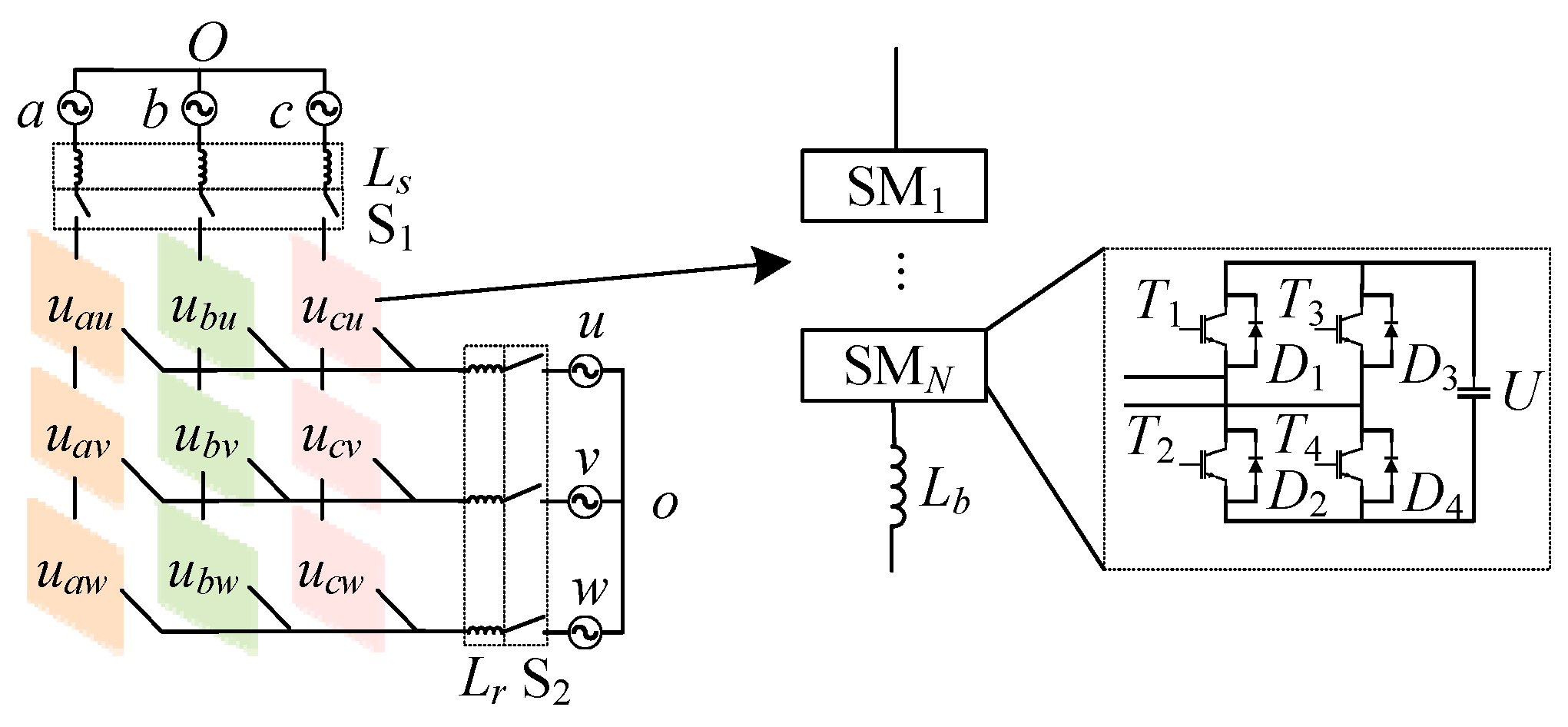
2.1. The Mathematical Model of M3C

The M3C bridge topology is shown in Figure 1. The system utilizes three-phase input and three-phase output with nine bridge arms, each having an identical configuration. Each bridge arm consists of N identical submodules (SMs) and an inductor connected in series. In the figure, S1 and S2 control the connection of the current-limiting resistor and the three-phase load, respectively. Each module is comprised of four IGBTs, four anti-parallel diodes, and one capacitor. The module is capable of outputting three voltage levels: 0, ±U, which are controlled by T1~T4. The module operates in one of four different modes, depending on the driving signals: block mode, charging mode, discharging mode, and bypass mode.

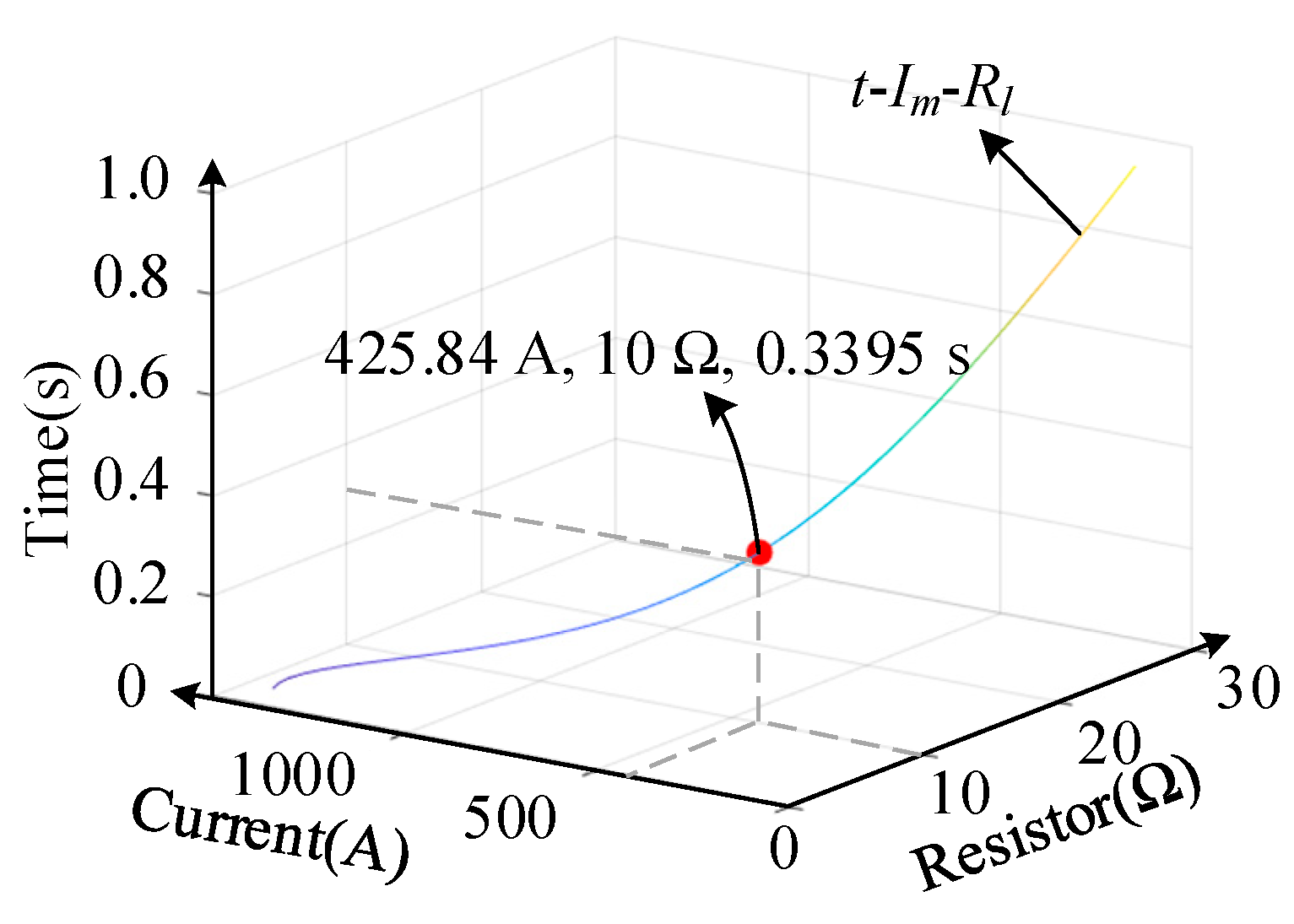
2.2. Selection of Current-Limiting Resistors

To ensure the secure operation of electronic equipment and prevent the inrush current from damaging the M3C system, a current-limiting resistor can be connected in series in the system. However, this will increase the system loss, and, therefore, a trade-off must be made to ensure safe pre-charging of the system by increasing part of the power consumption. The maximum charging current is generated when the AC line voltage reaches its peak for the first time. It can be expressed as follows:
I m = 6 U s R e 2 + X e 2 R e q = 2 3 R l = 6 R l X e q = 2 ω s ( 3 L s + L b ) N ω s C
where Im represents the inrush current when powered on, Us represents the effective value of the input-side phase voltage, Req represents the equivalent resistor in the circuit, Rl represents the current-limiting resistor in the circuit, Xeq represents the equivalent reactance, ωs represents the input-side frequency, and C represents the capacitance of the SMs.
The relationship between the current-limiting resistor and the current can be obtained by rearranging (1) as follows:
R l = 1 6 6 U s 2 I m 2 ω s ( 6 L s + 2 L b ) N ω s C 2
Furthermore, the required charging speed is affected by the value of the current-limiting resistor. The cutoff frequency of the circuit can be expressed as follows:
f 0 = 1 2 π L e q C e q
When the input frequency of the topology exceeds the cutoff frequency, the charging rate decreases as the capacitors’ voltage continues to increase. The capacitor is deemed fully charged when its voltage reaches 95%. The charging time for the capacitor in a DC RC circuit is calculated as follows:
v c = 6 U s ( 1 e t τ ) τ = R e q C e q = 6 R l C 2 N = 3 R l C N t = 3 R e q C e q = 9 R l C N
However, when charging all SM capacitors in full-bridges with AC voltage, the capacitor is consistently charged in the forward direction. The charging time is affected by a fixed value k0 when the number of SMs, the capacitor voltage, and the current-limiting resistor are fixed. Therefore, the charging time for all SM capacitors in the bridge with AC voltage can be expressed as follows:
t = 9 k 0 R l C N
When the ratio of the input voltage to the CCV at the completion of charging remains constant, the charging time is unaffected by the input voltage. After analyzing a large dataset, we can express the fitting equation as follows:
t = ( 14.2 + 12 R l ) C N + 0.004
Bring (5) into (6) as follows:
k 0 = N 2250 R l C + 71 45 R l + 4 3
Another limitation of the current-limiting resistors can be obtained as follows:
R l = ( t 0.004 ) N 12 C 71 60
In summary, the equation for obtaining the current-limiting resistor is as follows:
R l = 1 6 6 U s 2 I m 2 ω s ( 6 L s + 2 L b ) N ω s C 2 R l = ( t 0.004 ) N 12 C 71 60
The first equation is derived based on the maximum allowable charging current, ensuring that the inrush current does not exceed the rated capacity of the power devices. The second equation focuses on the desired charging time and is more relevant for setting the time constant to achieve a target voltage within a specific duration. Choosing the appropriate current-limiting resistor in practical applications can depend on factors such as the circuit’s rated current, the power device’s maximum current, and the charging time.

3. The NLM-Based Pre-Charging Strategy of M3C

The traditional pre-charging strategy does not address the inrush current problem during the transition to the controllable stage when CPS-PWM is utilized. Additionally, as the number of SMs increases, continuing the use of CPS-PWM would result in the loss of several benefits. To overcome these limitations, this paper utilizes an improved NLM approach for M3C pre-charging control. By improving the traditional NLM and selecting specific SMs for insertion by sorting the number of SMs, the inrush current during the controlled pre-charging stage can be decreased.

3.1. Traditional NLM Pre-Charging Strategy

3.1.1. Number of SMs in Operation

The traditional NLM determines the number of SMs in operation based on the current bridge arm voltage reference vxy_ref (x∈{a, b, c}, y∈{u, v, w}) and the rated value of the capacitor voltage Uc. It can be represented as follows:
n x y = round ( | v x y _ r e f U c | )
where nxy is the number of SMs inserted in the xy bridge arm (x∈{a, b, c}, y∈{u, v, w}), and the round(x) is to round the nearest integer.
However, the traditional NLM cannot be directly used for pre-charging due to the potential generation of inrush current. In addition, as vxy_ref increases during switching, too many SMs may be inserted, leading to a larger current. Furthermore, the SM number judgment does not account for the issue of inrush current during the switching algorithm. Therefore, this paper improves the number of SMs inserted:
n x y = floor ( 2 U s v c )
where the floor(x) rounds down to the nearest integer, producing the largest integer that is less than or equal to the current value, and vc is the average capacitance voltage of all SMs in the current bridge arm.
The optimal number of active SMs is determined by evaluating the minimum value of SMs that can be used in the current bridge arm. It can ensure a suitable charging current during the charging stage. Especially when transitioning to the controllable stage, it can gradually transfer the voltage on the current-limiting resistor to the SM with a smaller voltage by sorting, which reduces the inrush current.
It is important to note that, when the number of SMs is small, the output voltage level decreases, and the bridge arm current exhibits significant second-order harmonic components. These harmonics arise from power imbalance and the reduced equivalent switching frequency per SM, which becomes more pronounced as the number of SMs decreases. Such harmonic distortion can adversely affect the accuracy of state judgment based on current waveforms. Therefore, before the bridge arm current is used for state detection, it must be processed through a band-pass filter to suppress the second-order harmonics and extract the fundamental component essential for accurate analysis.

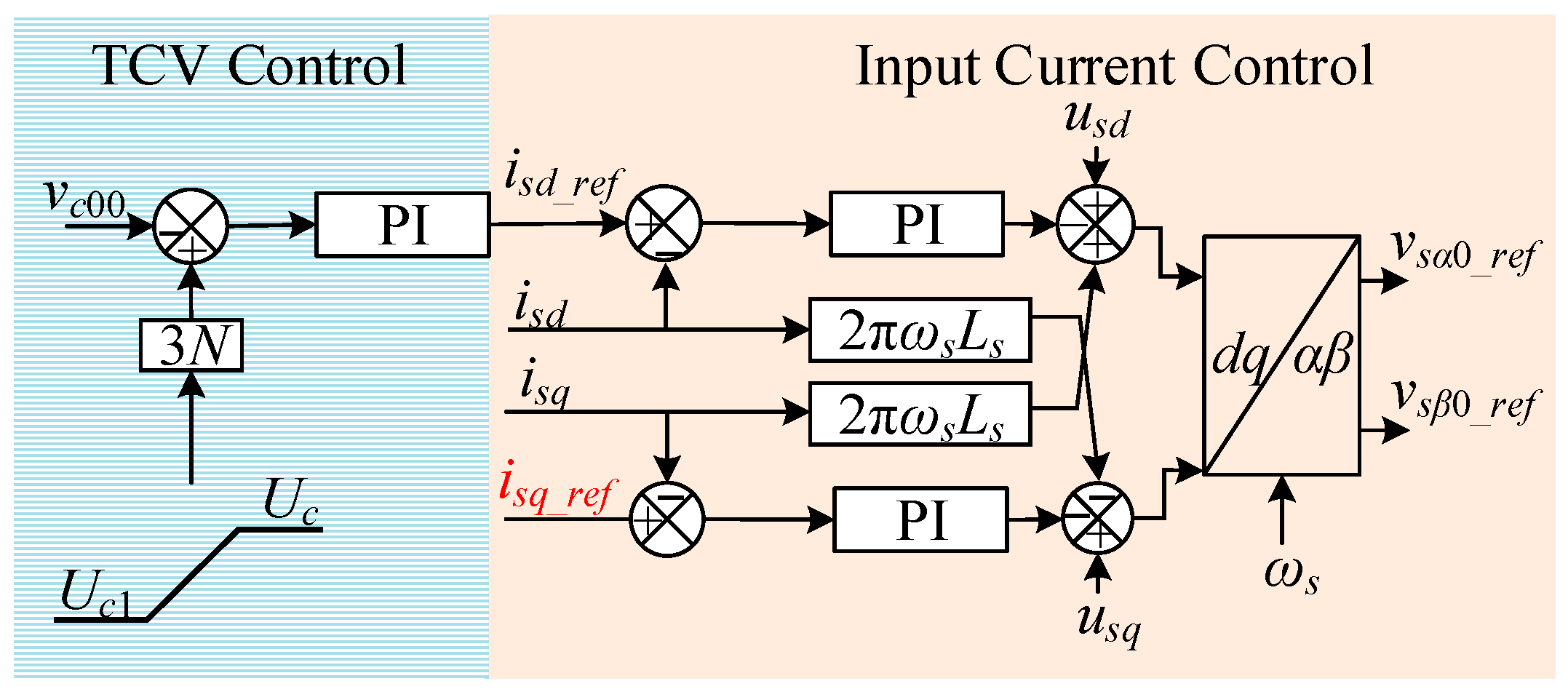
3.1.2. Input Reactive Current Compensation

Unlike the normal balancing process during M3C operation, an ideal charging process does not consume active power. Instead, it requires reactive power to be absorbed from the input grid and stored in the SM capacitors. To compensate for the reactive current during charging, this paper implements a control framework to achieve this goal, as shown in Figure 2. The energy absorbed by the capacitor during the charging process satisfies the following:
9 N 2 C ( U c 2 U c 1 _ a 2 ) = 9 N t 1 t 2 v c i s q _ r e f d t v c = U c 1 + k 1 ( t t 1 )
where k1 is the slope of the given TCV ramp function.
To facilitate analysis, it is assumed that the reactive current isq_ref remains constant:
i s q _ r e f = C ( U c 2 U c 1 2 ) 2 ( U c 1 k 1 t 1 ) ( t 2 t 1 ) + k 1 ( t 2 2 t 1 2 )
In addition, the controls on the input and output sides are considered, all of which utilize a dq decoupling control scheme. The reference values for the output active current ird_ref and reactive current irq_ref are set to zero. The NLM strategy tracks the given ramp function to accomplish the pre-charging operation of M3C.

3.2. Proposed NLM Pre-Charging Strategy

3.2.1. Quick-Sorting Algorithm

As the number of SMs increases, the computational burden of the NLM-based pre-charging strategy also increases. The bubble sorting algorithm, with its slow performance, may struggle to accurately track signals. In contrast, the quick-sorting algorithm not only outpaces the bubble sorting algorithm in speed but also boasts superior average time complexity.
This paper employs the quick-sorting algorithm-based NLM to perform the pre-charging operation of the M3C. Figure 3 presents an example of the quick-sorting algorithm operation using ten SMs.
The indices of SM voltage are utilized, and the operation is carried out based on both their indices and values. The rules for the quick-sorting algorithm are specified as follows:
① Select the first SM as the pivot (Replace with “P” in the figure) and define two pointers, which are L and R. The L pointer points to U1, and the R pointer points to U10.
② Move the R pointer to the left first. If Value[R] ≤ Value[P], stop moving the R pointer. Move the L pointer to the right until Value[L] ≥ Value[P].
③ Swap the data referred to by the L and R pointers. Repeat the operation in ② until the L and R pointers point to the same position.
④ Swap the position of the pointer and the data pointed to by the pivot.
⑤ Use the pivot as the dividing line and repeat from ① to ④ recursively. Continue until the values on both sides are arranged in order.

3.2.2. The M3C Pre-Charging Based on Improved NLM Strategy

The M3C pre-charging stage progresses according to a specific procedure: The initial values of all SM capacitance voltages are set to zero, and all SMs are blocked for uncontrolled pre-charging. When the bridge arm voltage reaches Uc1 at the end of the uncontrolled stage, the NLM controllable stage begins. Firstly, the optimal number of SMs nxy that can be permitted to enter the bridge arm is determined based on (11). Then, the capacitance voltages of the SMs currently collected are sorted using a quick sort algorithm from low to high. The charging and discharging states in this phase are determined in the same way as in bubble sorting. If the SM capacitance voltages are rated, M3C enters standby mode. Figure 4 shows the control signal flowchart during M3C pre-charging.

4. Simulation Analysis

4.1. Simulation Parameters

To verify the effectiveness of the proposed M3C pre-charging control strategy, we performed simulation analysis with MATLAB/Simulink. The simulation parameters are presented in Table 1.
Based on the simulation data, the cutoff frequency of the uncontrolled stage is determined as f0 = 10.33 Hz, which is lower than the input frequency fs. Figure 5 shows the range of the current-limiting resistor selection, with the optimal value shown on the line. In this paper, we selected a current-limiting resistor value of 10 Ω. Using Equation (9), the time t1 of the uncontrolled stage is calculated to be 0.336 s, and the inrush current is 425.84 A. The voltage Uc1 when the traditional uncontrolled stage of pre-charging ends is calculated to be 606.25 V. The time t1 of the uncontrolled stage is calculated to be 0.336 s, and the inrush current is 425.84 A. The SM capacitance voltage is set to Uc = 2000 V, the value of isq_ref is set to 233 A, and the time for the controllable stage to increase voltage according to slope is set to 0.30 s.
The bridge arm inrush current in the uncontrollable stage, the bridge arm inrush current during switching, and the maximum bridge arm current in the controllable stage are represented by I0, It, and Icm, respectively. Similarly, the input inrush current in the uncontrollable stage, the input inrush current during switching, and the maximum input current in the controllable stage are represented by Is0, Ist, and Iscm, respectively.

4.2. Pre-Charging of M3C Based on CPS-PWM Strategy

Figure 6a,b are the waveforms of the nine bridge arm voltages and currents using the CPS-PWM strategy. It can be seen that I0 is about 469 A, which is close to 425.84 A. At 0.34 s, uncontrolled charging completion aligns with the theoretical value of 0.3395 s and enters the controllable stage of the CPS-PWM strategy. However, the CPS-PWM has a sudden increase in bridge arm voltage and bridge arm current. Specifically, at the switching moment, It is 1270.36 A, because the voltage across the current-limiting resistor is transferred to the SMs. It causes a voltage of 1159.00 V, with a voltage difference with respect to 40 kV, and Icm is 1513.64 A. At 0.65 s, the charging reaches the rated value and enters the standby mode for normal operation of M3C. The controllable stage charging time is 0.31 s, which is close to the set value of 0.30 s.
Figure 6c shows the waveform of the capacitance voltage of 20 SMs on one bridge arm under the CPS-PWM strategy. During the charging process, the capacitance voltage of the bridge arm SMs increases synchronously, but there are notable fluctuations among the 20 SMs, with a range of approximately 11.80 V with respect to 2000 V. Figure 6d shows the waveform of the three-phase input current. Ist is about 3772.91 A on the input side during stage switching, which will have a significant impact on the converter.

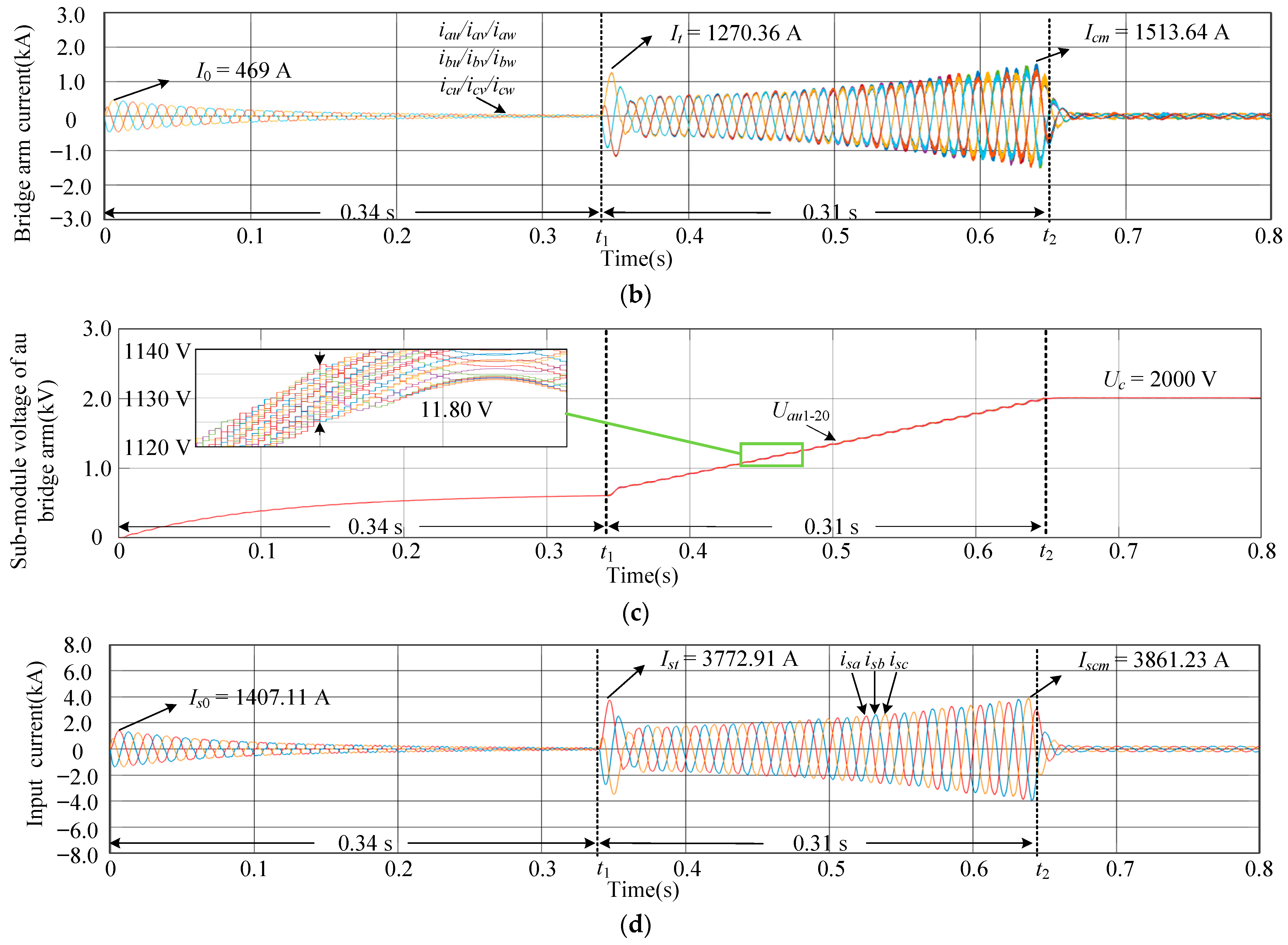
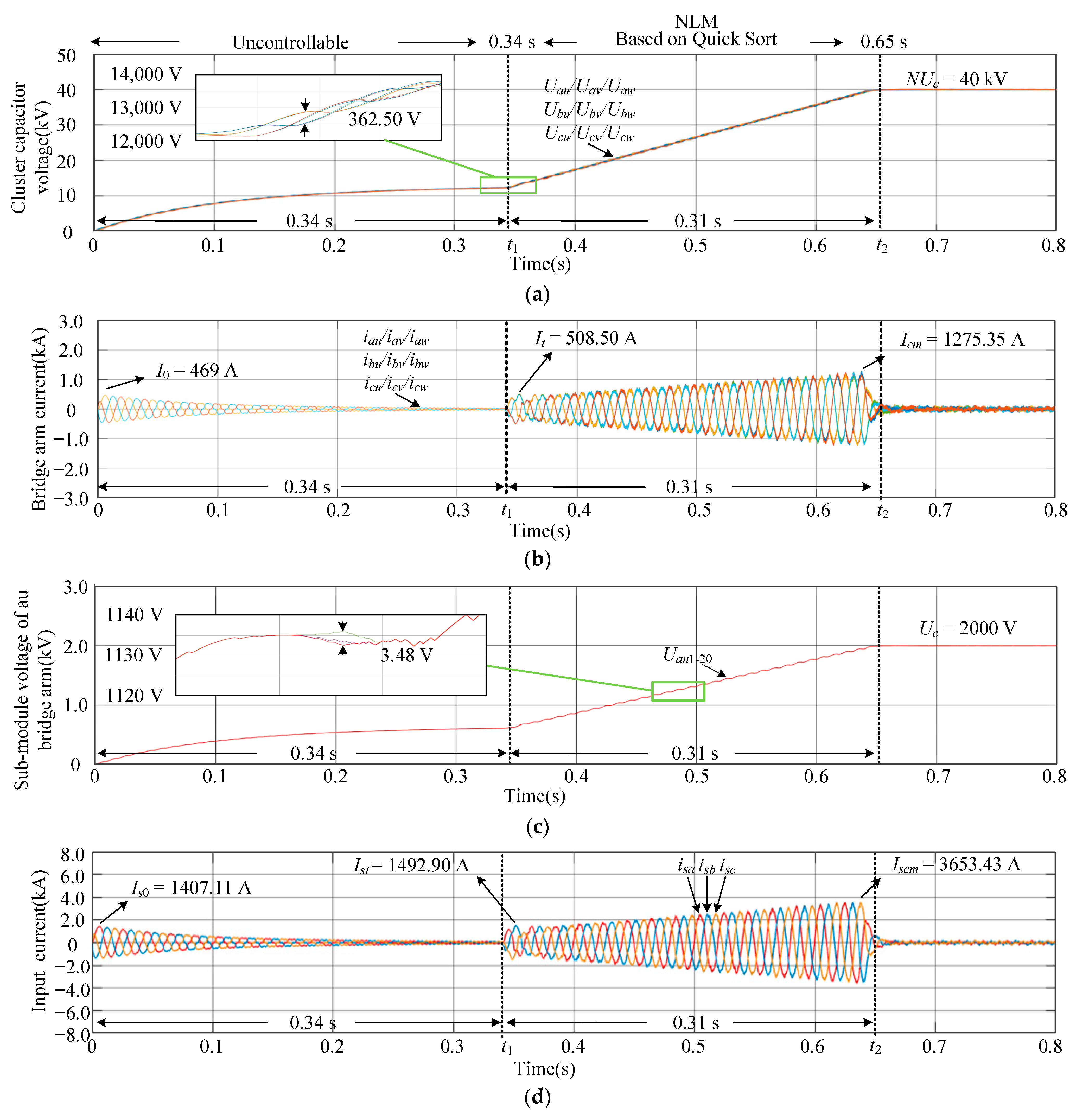
4.3. Pre-Charging of M3C Based on NLM Strategy with Quick-Sorting Algorithm

Figure 7a,b shows the waveforms of the bridge arm voltage and current controlled by M3C pre-charging based on the NLM strategy with the quick-sorting algorithm. At the moment of switching to the controllable stage, It is 508.50 A. Additionally, the sub-converters maintain balance, only experiencing a 362.50 V swing with respect to 40 kV, and the fluctuation in CCV of 61.11 V is reduced compared to the bubble sort algorithm. Additionally, Icm is 1275.35 A, which is reduced by 78.25 A compared to the bubble sorting. The M3C pre-charging stage finishes at 0.65 s, while the charging time of the controllable stage is 0.31 s.
Figure 7c shows the SM capacitance voltage waveform of 20 SMs on one bridge arm based on the NLM strategy with the quick-sorting algorithm. The synchronization of the SM capacitance on the bridge arm is significantly enhanced when compared to the bubble sort algorithm, with a maximum difference of 3.48 V with respect to 2000 V. The 20 SMs grow almost synchronously. Figure 7d shows the waveform of the three-phase input current, and Ist is 1492.90 A.
In this paper, from 100 to 2000 pieces of data are sorted, and the average time required to process the same data is compared between the quick-sorting algorithm and the bubble sorting algorithm for different amounts of data, and the time required is shown in Figure 8a. It is apparent that, when sorting data, particularly with substantial quantities of data, the quick-sorting algorithm requires significantly less time than the bubble sorting algorithm. Figure 8b shows the comparison of the state switching rate between the quick-sorting algorithm and the bubble sorting algorithm under different simulation time steps. The quick-sorting algorithm exhibits a higher number of state transitions under the three simulation time steps. Furthermore, the smaller the simulation time step, the larger the amount of data that needs to be processed. This indicates that the quick-sorting algorithm is faster than the bubble sorting algorithm in terms of sorting speed and has an advantage in processing larger amounts of data.
In summary, compared with the CPS-PWM, the NLM has been greatly reduced in terms of inrush current, bridge arm voltage fluctuation, maximum bridge arm current, and switching frequency during charging. Compared with the NLM based on the bubble sorting algorithm, the improvement effect of the bridge arm inrush current based on the quick-sorting NLM is relatively small. However, the advantage of the quick-sorting algorithm is to reduce the fluctuation of capacitor voltage, and the improvement effect on the fluctuation of the capacitor voltage between the phases and bridge arms is obvious.

5. Experiment Validation

To validate the effectiveness of the proposed NLM-based M3C pre-charging strategy, an experimental prototype was built with three SMs per bridge arm. The control system is composed of a dSPACE platform and an EP4CE10 FPGA, ensuring coordinated control and real-time response. The key experimental parameters are listed in Table 2.
Figure 9, Figure 10 and Figure 11 present the experimental results, which demonstrate a stable voltage rise, effective suppression of inrush current, and balanced capacitor charging, confirming the practicality of the proposed method. These results verify the feasibility of the proposed pre-charging method under practical conditions and confirm its suitability for a modular multilevel matrix converter.

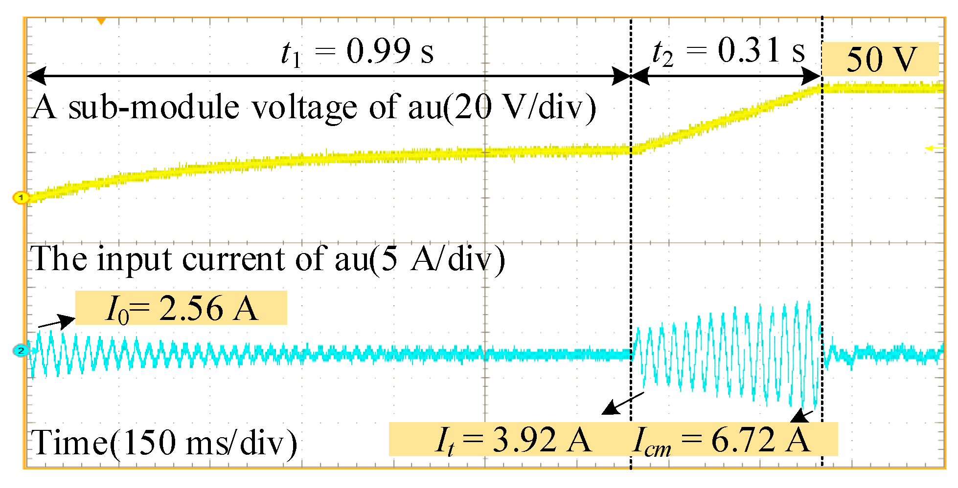
5.1. M3C Pre-Charging Strategy Based on CPS-PWM Strategy

At a carrier frequency of 1 kHz, the modulation ratio is 1, and the controllable stage time is 0.30 s. Figure 9 shows the capacitance voltage of an SM on ch1 and the current of a bridge arm on ch2.
It can be observed that, at around 0.99 s, the uncontrollable pre-charging is completed, and the switch to CPS-PWM occurs. At 1.30 s, the pre-charging operation is completed, and the system enters the standby mode of normal M3C operation. In the experiment, I0, It, and Icm are 2.56 A, 5.88 A, and 6.95 A, respectively. The uncontrollable stage time t1 and the inrush current I0 are respectively in agreement with 0.984 s and 2.45 A. The controllable stage lasted for 0.31 s, which is essentially consistent with the set time of 0.30 s. The control effect is good.

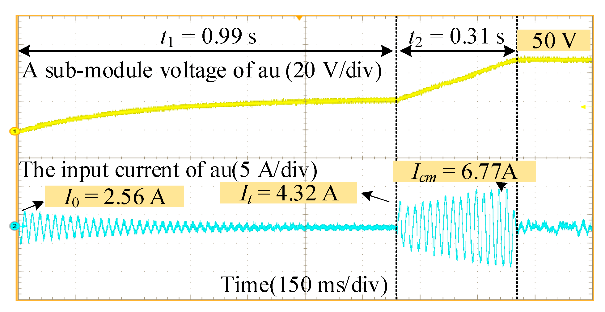
5.2. Bubble Sorting Algorithm-Based NLM Strategy

The experimental results are shown in Figure 10. Keeping the control strategy unchanged during the uncontrollable stage, this strategy completes the uncontrollable pre-charging at 0.99 s and reaches the rated value at around 1.30 s.
The It and Icm are 4.32 A and 6.77 A, respectively, which are reduced by 1.56 A and 0.18 A from CPS-PWM, respectively. Additionally, the switching frequency is low, around 0.72 kHz, representing an average value.
It is indicated that the NLM modulation strategy significantly reduces the inrush current during switching moments, as well as the bridge arm current during the controllable stage.

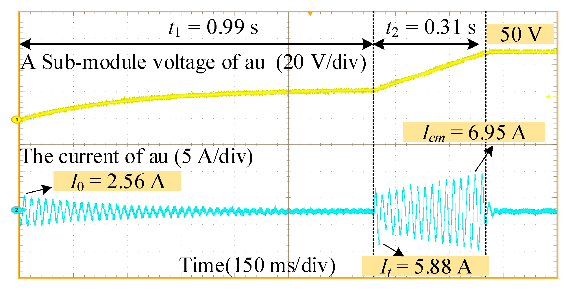
5.3. Quick-Sorting Algorithm-Based NLM Strategy

The experimental results of this strategy are shown in Figure 11. This strategy completes the uncontrollable pre-charging at 0.99 s and reaches the rated value at around 1.30 s.
The It and Icm are 3.92 A and 6.72 A, respectively, which are reduced by 0.40 A and 0.05 A from the bubble sorting algorithm, respectively.
Compared to the NLM based on the bubble sorting algorithm, the quick-sorting algorithm not only generates smaller inrush currents during the switching moment but also exhibits significantly lower bridge arm currents during the charging process. This is due to the faster sorting of SM in the quick-sorting algorithm, especially in cases of high power and a larger number of SMs, where the superiority of the quick-sorting algorithm is even more evident.

6. Conclusions

This paper presents a closed-loop fast pre-charging strategy using NLM instead of the traditional PWM-based pre-charging strategy. This paper proposes an improved NLM strategy for M3C pre-charging by reducing the number of input sub-modules, which effectively decreases the inrush current during grid connection, and switching to the controllable stage, thereby ensuring converter safety. Furthermore, this paper discusses the injection of reactive current to ensure stable capacitor step-up. To minimize fluctuations in the cluster capacitor voltage and the sub-module capacitor voltage during the pre-charging process, the quick sort algorithm replaces the bubble sort algorithm. The feasibility and reliability of the pre-charging strategy have been verified through simulation analysis and experimental validation.

Author Contributions

Conceptualization, R.H. and H.L.; methodology, Y.L. and Y.P.; software, Y.M. and F.H.; validation, R.H., H.L. and W.L.; writing—original draft preparation, Y.L., Y.P., Y.M. and F. H.; writing—review and editing, H.L. and W.L.; supervision, R.H., H.L. and W.L.; funding acquisition, R.H. All authors have read and agreed to the published version of the manuscript.

Funding

This research was funded by the key technology project of China Southern Power Grid Co., Ltd., grant number STKJXM20210102.

Data Availability Statement

The original contributions presented in this study are included in the article; further inquiries can be directed to the corresponding author.

Conflicts of Interest

Author Rufei He, Yikai Li, Yumin Peng, Yiming Ma and Fanqi Huang were employed by the company Energy Storage Research Institute of Southern Power Grid Peak shaving and Frequency Modulation Power Generation Co., Ltd. Author Hailong Li was employed by the company Shenzhen Hopewind Electric Co., Ltd. The remaining authors declare that the research was conducted in the absence of any commercial or financial relationships that could be construed as a potential conflict of interest.

References

  1. Liu, S.; Zhao, B.; Wang, G.; Wang, X. An Improved Phasor Method for Modelling and Analysis of Modular Multilevel Matrix Converter. IEEE Trans. Power Del. 2021, 36, 1744–1755. [Google Scholar] [CrossRef]
  2. Yan, Y.; Sun, Y.; Teixeira, C.; Ma, J.; Asif, M. Enhanced dynamic voltage balance control of modular multilevel matrix converters with switched circulating current control. In Proceedings of the IEEE 9th International Power Electronics and Motion Control Conference (IPEMC2020-ECCE Asia), Nanjing, China, 29 November–2 December 2020; pp. 3391–3396. [Google Scholar]
  3. Sun, Y.; Yan, Y.; Teixeira, C.; Ma, J.; Asif, M. Inter-arm voltage balance control of a modular multilevel matrix converter with injecting dual frequency circulating current. In Proceedings of the IEEE 9th International Power Electronics and Motion Control Conference (IPEMC2020-ECCE Asia), Nanjing, China, 29 November–2 December 2020; pp. 2396–2401. [Google Scholar]
  4. Kawamura, W.; Chiba, Y.; Hagiwara, M.; Akagi, H. Experimental verification of TSBC-based electrical drives when the motor frequency is passing through, or equal to, the supply frequency. In Proceedings of the IEEE Energy Conversion Congress and Exposition (ECCE), Montreal, QC, Canada, 20–24 September 2015; pp. 5490–5497. [Google Scholar]
  5. Li, B.; Zhang, Y.; Xu, D.; Yang, R. Start-up control with constant precharge current for the modular multilevel converter. In Proceedings of the IEEE 23rd International Symposium on Industrial Electronics (ISIE), Istanbul, Turkey, 1–4 June 2014; pp. 673–676. [Google Scholar]
  6. Tian, K.; Wu, B.; Du, S.; Xu, D.; Cheng, Z.; Zargari, N.R. A simple and cost-effective precharge method for modular multilevel converters by using a low-voltage DC Source. IEEE Trans. Power Electron. 2016, 31, 5321–5329. [Google Scholar] [CrossRef]
  7. Huo, X.; Xie, X.; Wu, Z.; Dou, X. A novel strategy for DC distribution start-up based on MMC. In Proceedings of the IEEE Sustainable Power and Energy Conference (iSPEC), Beijing, China, 21–23 November 2019; pp. 952–956. [Google Scholar]
  8. Yan, F.; Wang, P.; Zhang, X.-P.; Xie, J.; Li, X.; Tang, C.; Zhao, Z. Coordinated start-up control and inter-converter oscillations damping for MMC-HVDC grid. IEEE Access 2019, 7, 65093–65102. [Google Scholar] [CrossRef]
  9. Zhu, K.; Deng, F.; Chen, S.; Hou, J.; Abulanwar, S.; Ufa, R. An AC-side start-up scheme for thyristor-based modular multilevel converters. In Proceedings of the IEEE International Power Electronics and Application Conference and Exposition (PEAC), Guangzhou, China, 4–7 November 2022; pp. 1426–1431. [Google Scholar]
  10. Dekka, A.; Wu, B.; Zargari, N.R. Start-up operation of a modular multilevel converter with flying capacitor submodules. IEEE Trans. Power Electron. 2017, 32, 5873–5877. [Google Scholar] [CrossRef]
  11. Das, A.; Nademi, H.; Norum, L. A method for charging and discharging capacitors in modular multilevel converter. In Proceedings of the 37th Annual Conference of the IEEE Industrial Electronics Society, Melbourne, VIC, Australia, 7–10 November 2011; pp. 1058–1062. [Google Scholar]
  12. Liu, W.; Li, K.-J.; Liu, Z.; Wang, M. A simple and novel precharging control strategy for modular multilevel converter. IEEE Access 2019, 7, 170500–170512. [Google Scholar] [CrossRef]
  13. Qin, J.; Debnath, S.; Saeedifard, M. Precharge strategy for soft startup process of modular multilevel converters based on various sm circuits. In Proceedings of the IEEE Applied Power Electronics Conference and Exposition (APEC), Long Beach, CA, USA, 20–24 March 2016; pp. 1528–1533. [Google Scholar]
  14. Shi, K.; Shen, F.; Lv, D.; Lin, P.; Chen, M.; Xu, D. A novel start-up scheme for modular multilevel converter. In Proceedings of the IEEE Energy Conversion Congress and Exposition (ECCE), Raleigh, NC, USA, 15–20 September 2012; pp. 4180–4187. [Google Scholar]
  15. Xu, L.; Luo, Y.; Song, Y.; Blaabjerg, F. A smooth startup strategy for hybrid MMC based HVDC systems. Int. J. Electr. Power Energy Syst. 2021, 133, 0142–0615. [Google Scholar] [CrossRef]
  16. Li, B.; Xu, D.; Zhang, Y.; Yang, R.; Wang, G.; Wang, W.; Xu, D. Closed-loop precharge control of modular multilevel converters during start-up processes. IEEE Trans. Power Electron. 2015, 30, 524–531. [Google Scholar] [CrossRef]
  17. Wang, J.; Tang, Y.; Qi, Y.; Lin, P.; Zhang, Z. A unified startup strategy for modular multilevel converters with deadbeat predictive current control. IEEE Trans. Ind. Electron. 2021, 68, 6401–6411. [Google Scholar] [CrossRef]
  18. Li, A.; Lin, L.; Xu, C.; Hu, J. AC- and DC-side start-up strategies for half-/full-bridge hybrid modular multilevel converter. In Proceedings of the IEEE Applied Power Electronics Conference and Exposition (APEC), San Antonio, TX, USA, 4–8 March 2018; pp. 3121–3126. [Google Scholar]
  19. Zhang, L.; Qin, J.; Wu, X.; Debnath, S.; Saeedifard, M. A generalized precharging strategy for soft startup process of the modular multilevel converter-based HVDC systems. IEEE Trans. Ind. Appl. 2017, 53, 5645–5657. [Google Scholar] [CrossRef]
  20. Bissal, A.; Ali, W. A fast acting precharge control strategy for modular multilevel converters. In Proceedings of the IEEE 13th International Conference on Power Electronics and Drive Systems (PEDS), Toulouse, France, 9–12 July 2019; pp. 1–4. [Google Scholar]
  21. Liu, W.; Li, G.; Ugalde-Loo, C.E.; Liang, J. Start-up strategy for modular multilevel converters with modified nearest level modulation method. In Proceedings of the 8th Renewable Power Generation Conference (RPG), Shanghai, China, 24–25 October 2019; pp. 1–6. [Google Scholar]
  22. Sarwer, Z.; Sarwar, A.; Zaid, M.; Hussan, M.R.; Tariq, M.; Alamri, B.; Alahmadi, A. Implementation of a novel variable structure nearest level modulation on cascaded H-bridge multilevel inverter. IEEE Access 2021, 9, 133974–133988. [Google Scholar] [CrossRef]
Figure 1. Basic structure of full-bridge M3C.
Energies 18 02895 g001
Figure 2. TCV control and input side control based on a quick-sorting pre-charging strategy.
Energies 18 02895 g002
Figure 3. Schematic diagram of quick-sorting operation of ten SMs.
Energies 18 02895 g003
Figure 4. The control signal flow diagram of the proposed M3C pre-charging strategy.
Energies 18 02895 g004
Figure 5. The selection diagram of current-limiting resistor.
Energies 18 02895 g005
Figure 6. The simulation waveforms of traditional M3C pre-charging. (a) The bridge arm voltage of the nine arms. (b) The bridge arm current of the nine arms. (c) The SM capacitor voltage on one bridge arm. (d) The input currents.
Energies 18 02895 g006aEnergies 18 02895 g006b
Figure 7. The simulation waveforms of NLM pre-charging based on the quick-sorting algorithm. (a) The bridge arm voltage of the nine arms. (b) The bridge arm current of the nine arms. (c) The SM capacitor voltage on one bridge arm. (d) The input currents.
Energies 18 02895 g007
Figure 8. The comparison of the bubble sorting and quick-sorting algorithm speed. (a) The average time of the bubble sorting and quick-sorting algorithms under the same amount of data. (b) The number of state switches between the bubble sorting and quick-sorting algorithm at different simulation steps.
Energies 18 02895 g008
Figure 9. The experimental results of the M3C pre-charging strategy based on CPS-PWM.
Energies 18 02895 g009
Figure 10. The experimental results of the M3C pre-charging strategy based on NLM with the bubble sorting algorithm.
Energies 18 02895 g010
Figure 11. The experimental results of the M3C pre-charging strategy based on NLM with the quick-sorting algorithm.
Energies 18 02895 g011
Table 1. Simulation parameters of M3C.
ParameterValue
Input grid voltage vs/kV11
Output grid voltage vr/kV11
SM capacitance C/mF50
Input inductance Ls/mH8
Output inductance Lr/mH8
Arm inductors Lb/mH10
Sampling period Ts/µs10
Input frequency fs/Hz50
Output frequency fr/Hz50/3
Rated value of SM Uc/V2000
Number of SMs (per arm) N20
Table 2. Experimental parameters of M3C.
ParametersValue
Input grid voltage vs/V60
Output grid voltage vr/V60
SM capacitance C/mF22
Input inductance Ls/mH10
Output inductance Lr/mH10
Arm inductors Lb/mH5
AC Y-connect Load Ro15
Current-limiting resistor Rl10
Input frequency fs/Hz50
Output frequency fr/Hz50/3
Number of SMs (per arm) N3
Rated value of capacitor
voltage in SM Uc/V
50
Controllable stage time t/s0.3
Disclaimer/Publisher’s Note: The statements, opinions and data contained in all publications are solely those of the individual author(s) and contributor(s) and not of MDPI and/or the editor(s). MDPI and/or the editor(s) disclaim responsibility for any injury to people or property resulting from any ideas, methods, instructions or products referred to in the content.

