Article

Research on Torque Modeling of the Reluctance Spherical Motor Based on Magnetic Equivalent Circuit Method

by
Lufeng Ju
,
Honglei Liu
,
Guoli Li
*,
Qunjing Wang
and
Kangjian Zha
Department of Electrical Engineering and Automation, Anhui University, Hefei 230601, China
*
Author to whom correspondence should be addressed.
Energies 2025, 18(11), 2882; https://doi.org/10.3390/en18112882
Submission received: 22 April 2025 / Revised: 20 May 2025 / Accepted: 22 May 2025 / Published: 30 May 2025

Abstract

Torque modeling is an important research aspect of multi-degree of freedom (multi-DOF) spherical motors, and it is the key to realizing the accurate control of multi-DOF spherical motors. In this paper, a torque modeling method of the reluctance spherical motor (RSPM) based on the magnetic equivalent circuit (MEC) method is proposed. Firstly, the structure of the RSPM is introduced, and the MEC topology of the RSPM is obtained. The calculation formulas of the reluctances in this topology are given. Then the magnetic flux of the RSPM is solved by the mesh analysis method, and the torque is calculated based on the magnetic field energy storage. Finally, the calculated torque is verified by the finite element method (FEM). The verification results show that the torque modeling of the RSPM based on the MEC method is correct, which consumes less memory and time than the three-dimensional finite element method.

1. Introduction

Spherical motors [1] have broad application prospects and have received extensive attention in recent years due to their complex electromagnetic structure and multi-degree of freedom (multi-DOF) motion characteristics [2,3].
The spherical motor is a kind of special motor that can realize multi-DOF movement through only one joint. At present, the main issue in the field of spherical motors is how to realize the closed-loop control of motors. Closed-loop control comprises electromagnetic analysis, torque modeling [4,5], the excitation strategy [6], rotor position detection [7], and so on. The most critical and difficult part is electromagnetic analysis and torque modeling [8]. Electromagnetic analysis and torque modeling of spherical motors are mostly completed by the finite element method (FEM) [9]. The result of the FEM is accurate and convincing, but it has the disadvantages of long calculation time and requiring too many calculation resources. It is difficult to use as a fast calculation model in the real-time closed-loop control of spherical motors. Therefore, it is of great significance to explore how to establish a fast electromagnetic torque calculation model of the spherical motor [10].
The research on torque modeling of permanent magnet spherical motors has been performed for a long time, and a large number of research results have been published [11]. However, there is little mention of the nonlinear problems caused by ferromagnetic materials. A new type of reluctance spherical motor (RSPM) [12] has great development potential because it is made of ferromagnetic materials and has no permanent magnetic poles. Its working principle is similar to that of a switched reluctance motor [13,14]. It has the advantages of small volume, light weight, and large output torque. He et al. [15] proposed an analytical method for the three-dimensional magnetic field and torque of a permanent magnet spherical motor, where the electromagnetic force of the stator coil is calculated by the Lorentz force method. Therefore, this study will explore the establishment of the fast electromagnetic torque calculation model of the reluctance spherical motor.
In this paper, a torque modeling method of the RSPM based on the magnetic equivalent circuit (MEC) is proposed [16,17]. Its computational efficiency is very high. The MEC describes the magnetic flux, reluctance, and magnetomotive force sources in the magnetic circuit of the motor in the form of a circuit, according to the magnetization characteristics of ferromagnetic materials. Then the torque calculation model of the motor is established based on the MEC [18,19]. In this way, there is no need to know the relationship between the coil inductance, current, and rotor position. It is convenient to obtain the inverse torque model that can calculate the current, which reduces the storage pressure of the controller and is more suitable for the electromechanical system with a complex structure such as the RSPM.
The key novelties and contributions of this work are summarized as follows:
(1) The proposed model accounts for the influence of the nonlinear characteristics of ferromagnetic materials on torque generation.
(2) The analytical model incorporates the geometric parameters of the stator and rotor structures as well as the internal magnetic flux distribution, capturing the fundamental electromagnetic phenomena.
(3) Compared to other modeling methods, this approach achieves higher accuracy and computational efficiency.

2. RSPM Structure and Working Principle

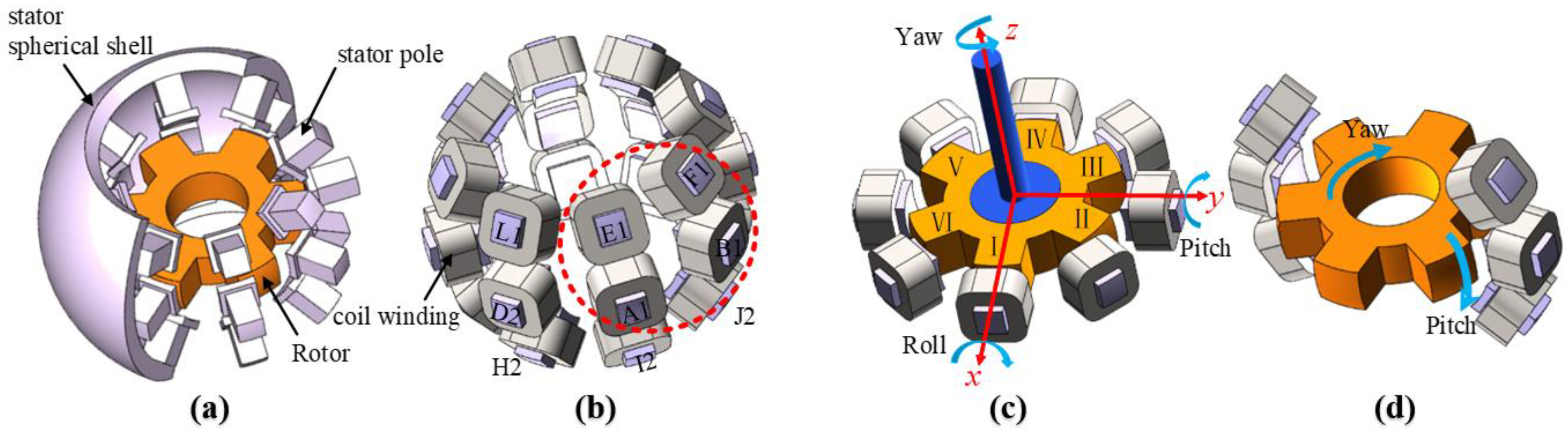
2.1. Basic Structure

The typical structure of the RSPM is shown in Figure 1 [20]. The stator, the rotor, and the air gap are spherical. The core of the rotor is made of stacked silicon steel sheets and wrapped by a nonmagnetic spherical shell. There are 6 centrosymmetric poles on the rotor. There are 3 layers of stator poles, 8 poles in each layer, evenly distributed across the spherical surface. The two magnetic poles that are opposite to each other are connected in series in the same direction to form a magnetic pole pair with the same direction of current and the same polarity, which is called a phase. In this way, there is the promotion of the output torque, the demotion of the complexity of the excitation strategy, and the geometrical symmetry of the motor magnetic field. The magnetic circuit is closed through the pole pairs, the air gap, and the rotor in sequence. The interaction force between the pole pair and the rotor varies with the level of winding current, which affects the movement of the rotor. The three layers of stator poles together affect the rotor, which performs a three-degree of freedom (3-DOF) motion.

2.2. Working Principle

There are 24 magnetic poles divided into 12 pairs of magnetic pole pairs with a spatial angle of 180°. The stator and rotor unfold horizontally along the output shaft, and the labels of the stator and rotor poles are shown in Table 1. If the labels contain the same capital letter, the two poles are in the same phase. The middle magnetic poles are divided into 4 phases, which are labeled as A to D. The upper magnetic poles and the lower magnetic poles on the diagonal become one phase, respectively, which are labeled as E to H. When the rotor pitches, either phase E or phase I is excited, and the difference between them is that the rotor pitches in the opposite direction. The same procedure may be easily adapted to phase F and phase J, phase G and phase K, and phase H and phase L. When the excitation strategy is considered, yaw and pitch need to be independent of each other, so only 8-phase pole excitation states are considered, such as A–D and E–H.
The classification of stator magnetic poles makes the control strategy of the motor clearer. The magnetic poles of the middle layer are excited in turn to make the rotor yaw, and the magnetic poles of the upper layer and the lower layer are excited in turn to make the rotor pitch or roll. Any movement of the rotor can be regarded as the synthesis of three single-degree of freedom movements of yaw, roll, and pitch. Pitch and roll can be thought of as pitching in the X or Y direction, respectively, with the same principle when implemented. Therefore, the motion of the rotor is simplified to yaw and pitch.

3. MEC of the RSPM

The MEC model is similar to a circuit in which the voltage source is replaced by the magnetomotive force (MMF) generated by the excited phase windings, the current is replaced by the magnetic flux, and the resistance in the circuit is replaced by the reluctance in the magnetic flux path. The MEC topology of the RSPM consists of various magnetic circuit elements. Any technique applicable to solving resistive circuits can be used to solve the MEC, including series combination, parallel combination, partial pressure, and shunt, all based on Kirchhoff’s laws. The advantages of the MEC method are that the number of elements and dimensions of the matrixes are much smaller than those of the FEM, no boundary conditions are involved, and the calculation speed is high.
The magnetic flux path of the RSPM consist of the air gap and magnetic poles and yokes of the stator and rotor. The process of changing from electrical energy to mechanical energy takes place in the air gap, where the stored energy is the most abundant. Because both the stator and rotor have salient poles, the air gap magnetic circuit and the connection between the stator and rotor have different forms with the movement of the rotor. Therefore, the MEC topology of the RSPM changes with the rotor rotation angle, too. Therefore, in the preprocessing of the MEC, the magnetic flux path should be determined first.

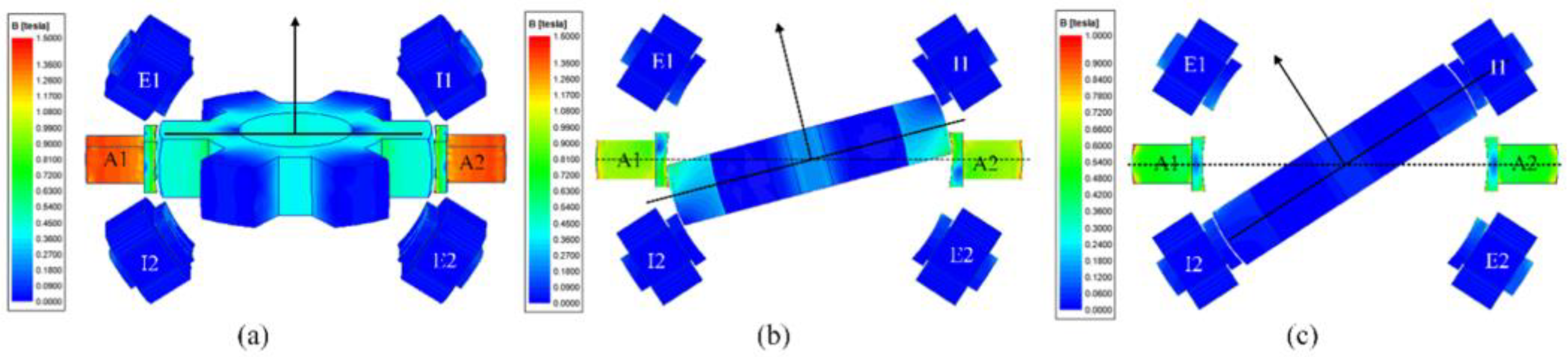
3.1. Magnetic Flux Path of the RSPM

Because there are two defined degrees of freedom, the period of the relative position of the magnetic poles of the stator and rotor of the RSPM is 60 degrees of yaw and 33 degrees of pitch, as surrounded by A1–B1–F1–E1 in Figure 1b. The conditions for the following characteristics are single-phase excitation within one period. The magnetic flux density distribution of several special positions of the rotor is shown in Figure 2, and the direction of the magnetic circuit can be clearly seen [21].
As can be seen from Figure 2 and Figure 3, the magnetic flux passes through the stator poles, the pole shoes, the air gap, the rotor pole, the rotor yoke, and then through the other completely symmetrical half and is finally shunted from the stator spherical shell to return to the excited phase. Because of symmetry, the magnetic flux path is divided by equipotential points into regions, also called nodes. These regions will be treated as linear or nonlinear reluctance or permeance. The nodes of the RSPM are selected as: the stator yoke node N1, the stator pole node N2, the air gap stator side node N3, the air gap rotor side node N4, and the rotor yoke node N5, as shown in Figure 4.
At the same time, it is also necessary to judge how these poles are connected to each other, especially from the stator to the rotor. In the FEM simulation, two magnetic density observation lines are taken at the air gap corresponding to the middle stator poles and the upper stator poles, respectively, as shown in Figure 5. Taking the excitation of phase A as an example, when the rotor moves in the range of 60° × 33°, the magnetic flux density at the air gap corresponding to these independent stator poles can be observed. The calculation results are shown in Figure 6, which describes the variation of the air gap flux density with the rotor rotation angle at different stator poles.
In Figure 6a, observation line 1 is positioned with the magnetic pole labels, within one period. The amplitude of the magnetic flux is more significant only near the excited phase. At this moment, the excited phase communicates with the nearest pair of rotor poles. The magnetic flux path breaks for a while around 30°, which is why the magnetic density is much lower than at other locations. After half a period, the excited pair of stator poles is in turn connected to another pair of rotor poles, which is approaching it. In Figure 6b, as the pitch angle increases, the air gap magnetic density decreases monotonically. There is no sudden change in the magnetic flux density when the rotor pole is close to the upper nonexcited magnetic pole. This shows that, although the pitch angle is large, the magnetic flux path only passes through the excited stator poles to the rotor and does not pass through the upper magnetic poles. In this process, the reluctance of the air gap continues to increase.
Next is the analysis of Figure 6c,d. In Figure 6c, regardless of the angle of yaw, the amplitude of the air gap flux density of the upper stator poles is relatively close and small. This means that the upper magnetic pole is not included in the magnetic circuit of the motor at this time. In Figure 6d, as the pitch angle increases, that is, the rotor gradually approaches observation line 2, the air gap magnetic density increases slightly but remains at the level of several milli-Tesla. This is because the leakage flux through the upper coil is insignificant when it is compared to the main flux, so this part is ignored when establishing the main flux path. The above conclusions highlight that, with single-phase excitation, the magnetic flux only passes through the excited stator poles to the nearest rotor poles. One stator pole corresponds to one rotor pole, nothing extra. This observation effectively simplifies how the MEC is connected, but only for single-phase excitation conditions. When the multi-phase excitation is performed, the magnetic flux path is shorter than that of the single-phase excitation, so it is necessary to re-analyze the magnetic flux path and solve the new magnetic circuit topology.

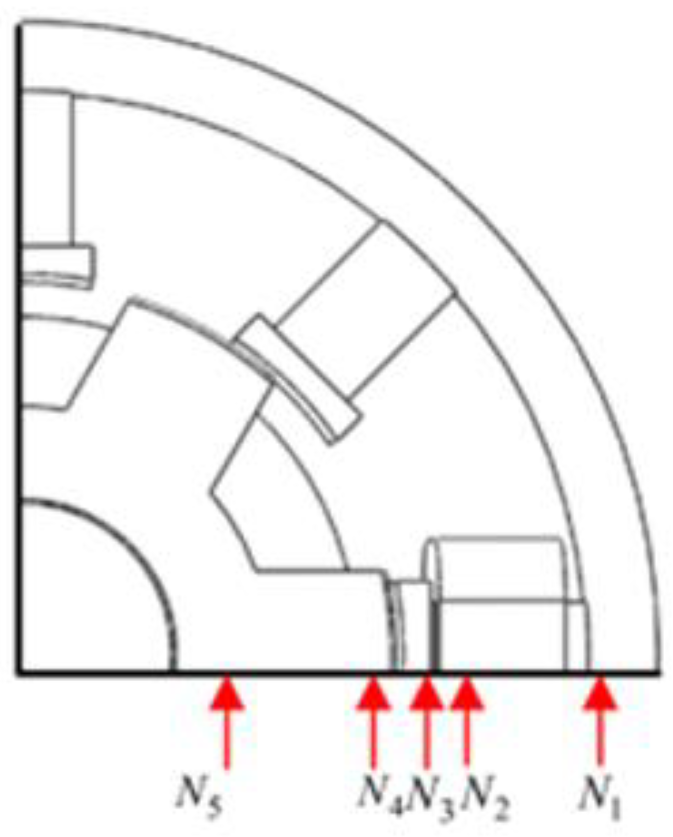
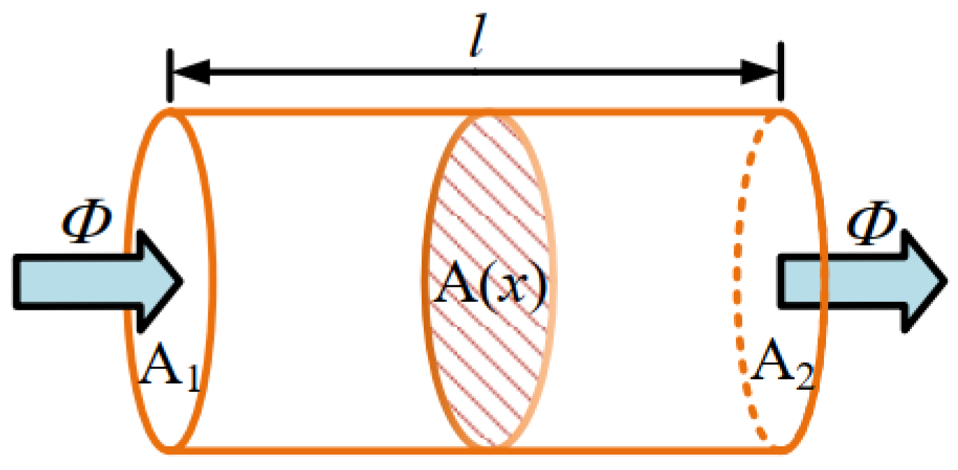
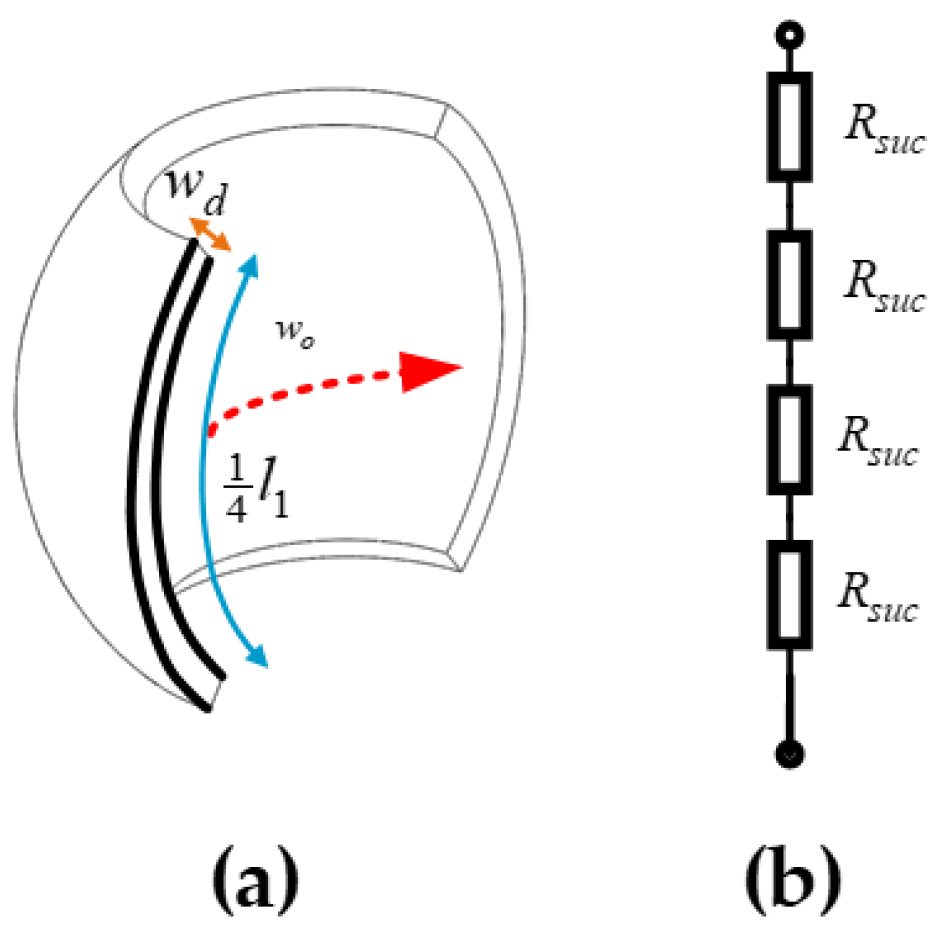
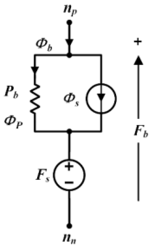
3.2. Calculation of Magnetic Reluctance Based on Equivalent Flux Tube

There are two types of components that appear in the MEC: active components and passive components. Active components are magnetic motive force sources (MMFSs) generated by excited windings, typically in series in the magnetic circuit.
F = Ni
where i is the phase current and N is the number of turns of the phase windings.
In the MEC, the passive elements are the parts made of magnetically permeable material in the motor, which is represented by the reluctance containing magnetic permeability. First, the reluctance of a flux tube is calculated. Several parts of the motor are similar to flux tubes, so the reluctance of the motor can also be calculated.
Figure 7 shows a uniform magnetically permeable sample. The magnetic flux Φ enters from the end face A1 and goes out from the other end face A2, and there is no magnetic flux leakage on the way. Let the cross-sectional area value be A(x). The path is perpendicular to the section and its length is l. Then the magnetic reluctance of the flux tube can be expressed as:
R x = 0 l d x μ Φ / A A
where μ(Φ/A) represents the permeability as a function of the magnetic flux density in a nonlinear magnetic system. Equation (2) shows that the reluctance is a function of two parameters: the shape of the flux tube and the properties of the magnetic material. In the magnetic flux path of the motor, some parts have a fixed shape and do not saturate, such as slots, which have a constant permeability that does not vary with magnetic flux. The reluctance of the part with constant permeability but variable size is related to the rotation angle of the rotor, such as the air gap. The shape of the iron core of a motor is generally unchanged, but due to the properties of the material, the permeability is related to the magnetic flux passing through.
According to the previous analysis, the reluctance of each part will be calculated separately, including the stator, rotor, and air gap. First, the parts of the magnetic flux path are abstracted by geometrical forms. Then the size values are substituted into the reluctance calculation formula of the equivalent flux tube.
(1).
The reluctance network of the stator.
As shown in Figure 8, the distribution of the stator poles affects the division of the stator spherical shell, in which there are 24 independent nodes. These nodes are connected with the reluctance of the air gap and the reluctance of the rotor to form different flux paths under different conditions.
Each node includes MMFSs, the smallest unit flux tube of the stator spherical shell R suc ( Φ ) , the reluctance of the stator pole R stc ( Φ ) , and the reluctance of the stator pole shoe R stc ( Φ ) . The structure of the segmented spherical shell reluctance, shown in Figure 9a,b, is its form in the reluctance network of the stator. From Figure 9, we can obtain
R suc ( Φ ) = w o 1 4 l 1 w d μ B Φ 1 4 l 1 w d
where l1 represents the minimum arc length of the stator spherical shell and wd represents the thickness of the spherical shell.
The reluctance of the stator pole R stc ( Φ ) is shown in Figure 10a, and the reluctance of the stator pole shoe R sbc ( Φ ) is shown in Figure 10b. From Figure 10, we can obtain
R stc ( Φ ) = w 1 l 2 2 μ B Φ l 2 2
R sbc ( Φ ) = w 2 l 3 3 μ B Φ l 3 3
where l2 represents the stator pole width, w1 denotes the stator pole length, l3 indicates the pole shoe width, w2 stands for the pole shoe thickness.
(2).
The reluctance network of the rotor.
The rotor has 6 poles. According to the relative position and excitation distribution of the stator and rotor poles, there are three possible situations in the rotor magnetic flux path: only one pair of poles is conducting, two pairs of poles are conducting, and three pairs of poles are conducting, which needs to be judged by known conditions (see Figure 11). The yoke of the rotor is evenly divided into 6 parts as the smallest unit. The expression of reluctance of the 1/6 rotor yoke R ruc ( Φ ) and the reluctance of the rotor pole R rtc ( Φ ) can be obtained from Figure 11, and they can be expressed as
R ruc ( Φ ) = w 4 l 4 l 5 μ B Φ l 4 l 5
R rtc ( Φ ) = w 3 l 4 2 μ B Φ l 4 2
where l4 represents the rotor pole width, w3 denotes the rotor pole thickness, l3 indicates the rotor yoke width, w4 stands for the arc length of the 1/6 rotor yoke.
(3).
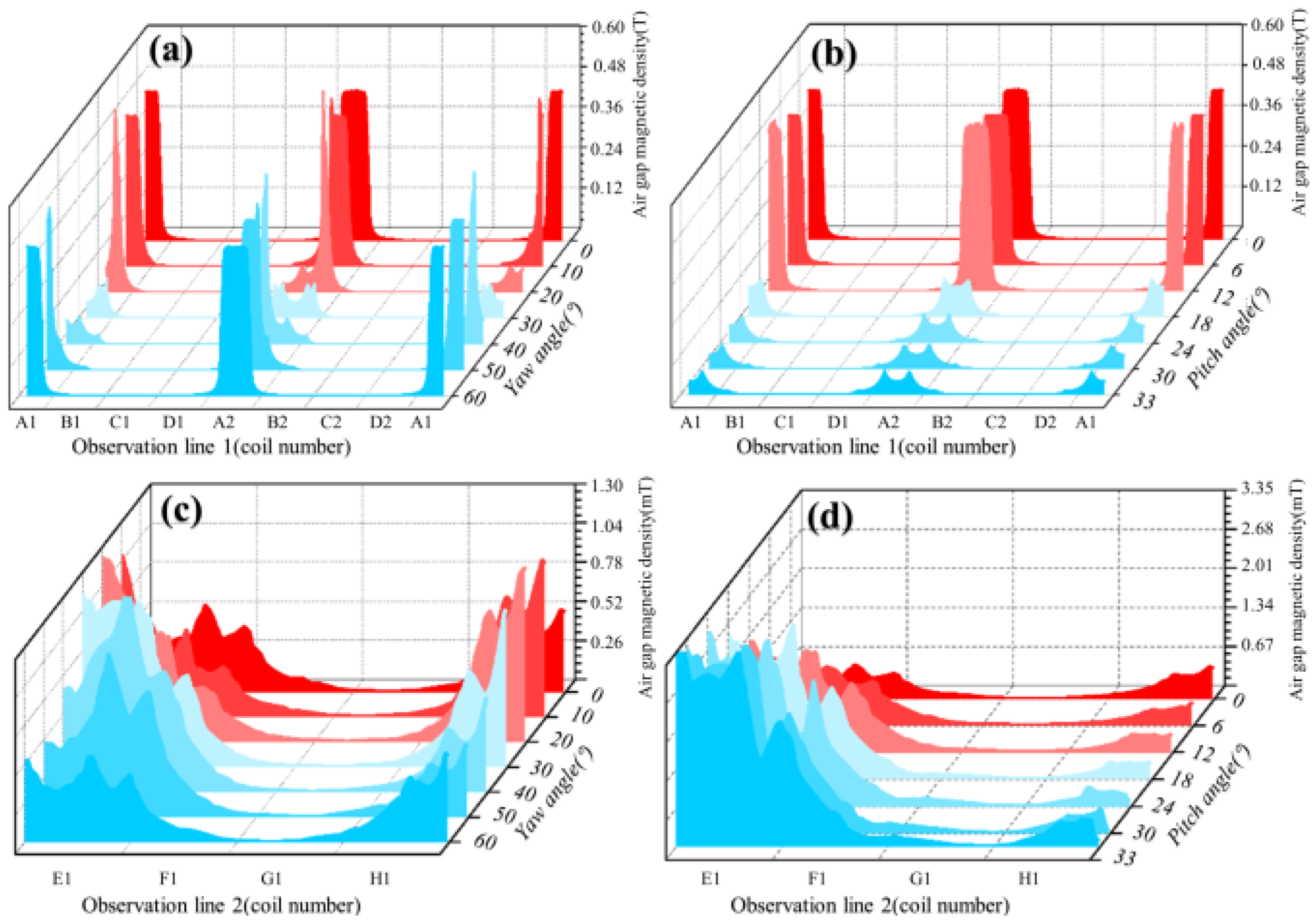
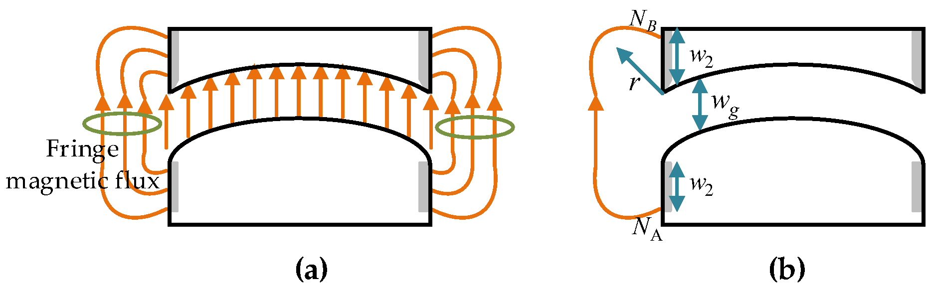
The reluctance of the air gap.
First, the reluctance of the air gap is calculated when the stator and rotor poles are aligned. At this time, the magnetic flux path of the motor is the shortest, the reluctance is the smallest, and the reluctance of the air gap is also the smallest, which is shown in Figure 12a.
The reluctance of the air gap R g can be expressed as
R g = w g μ 0 l 3 l 4 ln l 3 l 4
where wg represents the air gap width, while the meanings of l3 and l4 are the same as in Equations (5) and (6).
Air gaps are different from each other because the magnetic flux passes through two different mediums of space. In this way, the magnetic field lines must pass through a nonstraight path at the interface, and this part of the magnetic flux is called the fringe flux, the addition of which makes the MEC more accurate. The fringe flux is in parallel with the main flux, just like in a circuit (see Figure 13). Representing it as a permeance would make the calculation easier because it can be added directly.
The fringe permeance P f a is calculated according to Figure 13b.
P fa = μ 0 l 3 π ln ( 1 + π w 2 w g )
where l3, w2, and wg are the same as those in the equations above.
So far, every component of the motor’s magnetic circuit has been mathematically modeled. Table 2 lists the parameter values used in the motor.
In practice, fringe permeance exists on all four sides of the stator and rotor pole, as shown in Figure 13a. Therefore, the total air gap permeance of the motor can be expressed as:
P gd = P g + 4 P f a
During the rotation of the motor, the value of the reluctance of the air gap changes continuously. For the accuracy and uniformity of the MEC, the scale factor of the reluctance of the air gap is obtained from the FEM results, and the special scale factor is set to 1, when the stator and rotor poles are aligned. This makes the air gap reluctance be described over the entire period, accommodating any changes in the shape of the equivalent flux tube of the air gap. Figure 14 shows the scale factor of the reluctance of the air gap calculated by finite elements. It can be seen that the scale factor is 0 when it goes half a cycle in the yaw direction, since there is no connection between the stator poles and the rotor poles at this time. In the second half of the cycle, the excited stator poles are connected with the upcoming rotor pole pair. In the pitch direction, the reluctance increases first, then the larger value of the reluctance remains for a while and eventually decreases at a very fast rate. From the point where it starts to decrease, it is considered that the magnetic circuit is broken, otherwise the wrong result will be calculated. So far, each part of the magnetic flux path of the motor has been described by the mathematical model.

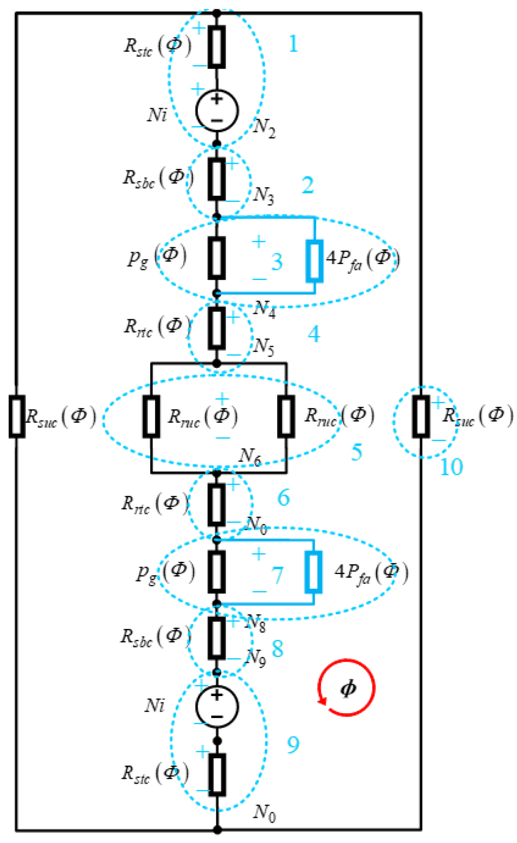
3.3. MEC Topology of the RSPM

The MEC topology of the RSPM is obtained by connecting the various magnetic components. Figure 15 is the MEC when the centerlines of the stator and rotor poles are aligned.
In this MEC topology, there are 10 branches. Each branch is represented by a blue dashed circle, along the direction of the MMF decline for each branch. The branches 2 and 8 are affected by the reluctance of the air gap, and the other branches are related to magnetic materials.

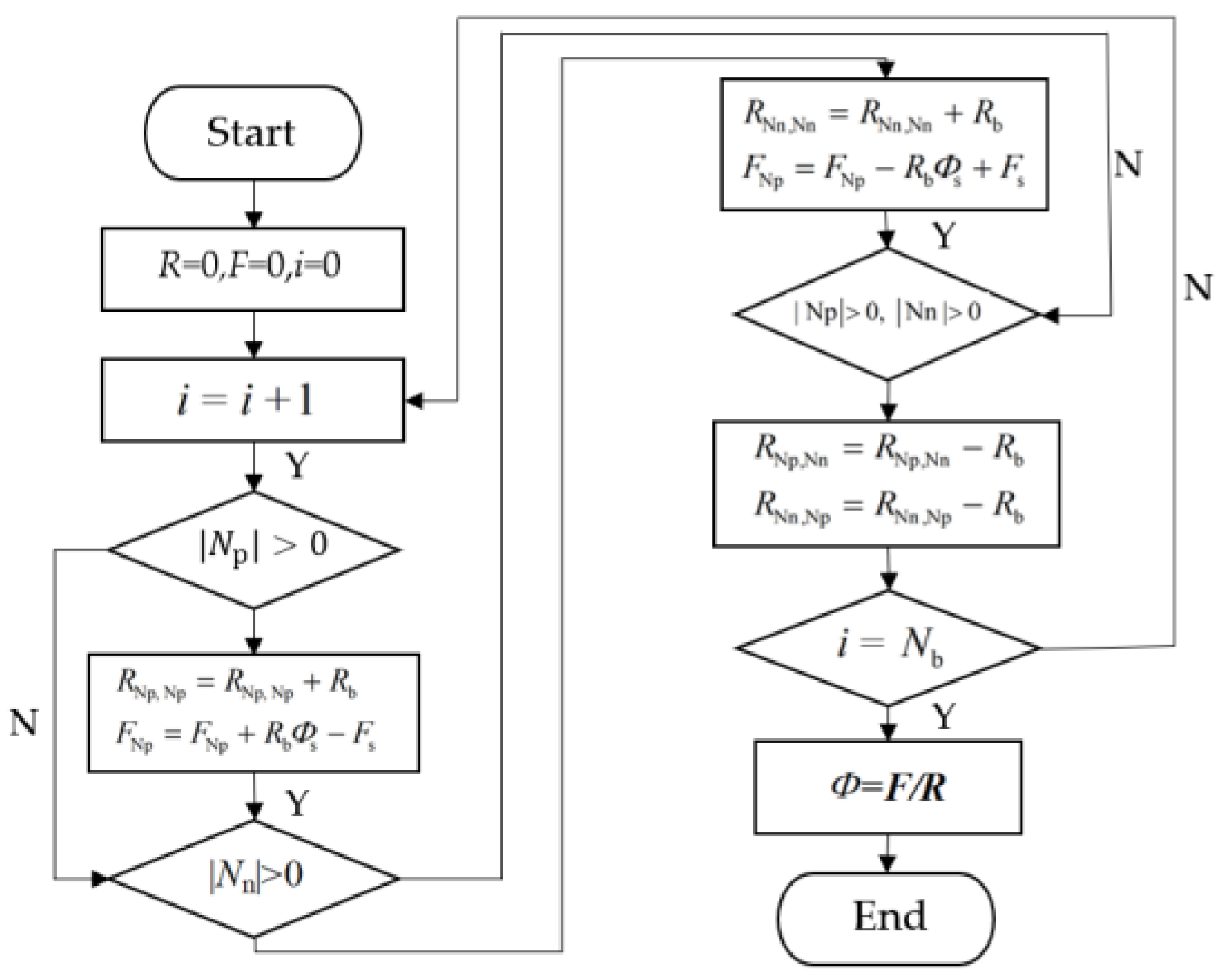
4. Torque Modeling of Nonlinear MEC

The nonlinear reluctance in magnetic circuits is the explicit dependence of branch magnetic fluxes. Therefore, the solution of the MEC is the branch magnetic flux, through which the flux linkage–current relationship of the motor can be obtained, and then the torque characteristics can be solved.

4.1. Mesh Analysis Method

According to the mesh analysis method, the system can be represented in the form of matrix equations.
R Φ = F
where R is the reluctance matrix. F is the MMF column vector. Φ is the mesh flux vector.
Their dimensions are related to the number of meshes Nm. The matrix equations are solved iteratively. During this process, the reluctance and flux density of each element are updated, and the nonlinearity of the ferromagnetic material is also considered. The algorithm flow chart of the mesh analysis is shown in Figure 16, and the influence of each branch on the mesh equation is calculated separately.
Where Nb is the total number of branches. Np represents the set of mesh magnetic flux flowing into the positive node of the branch. Nn represents the set of mesh magnetic flux flowing into the branch negative node. When they become subscripts, they indicate the position of the element in the matrix. “‖” denotes the number of the set.
The standard branch is shown in Figure 17, and the relationship between various physical quantities is described by the MMF balance equation.
F b = R b Φ R Φ b Φ s + F s
where Rb(ΦR) is the nonlinear reluctance. Φb is the magnetic flux flowing into the branch. Φs is the magnetic flux source (such as permanent magnet material). Fs is the MMFS (such as the windings). ΦR is the magnetic flux flowing through the reluctance, and Fb is the MMF drop of the branch.
The basic idea of solving nonlinear problems in an iterative process is to linearize the equations of all branches at the estimated solution. Then the result is substituted into a new calculation to obtain an improved solution. This process is repeated until the error function converges. Equation (12) is represented in the form of Taylor’s series, ignoring higher-order terms.
F b = F b 0 + F b Φ b Φ b 0 Φ b Φ b 0
R b 0 = l b μ B B b 0 A b
B b 0 = Φ b 0 Φ s A b
We can obtain the expression of the linearized branch:
F b F seff + R beff Φ b
F seff = F s + R b 0 S 0 Φ b 0 Φ s
R beff = F b Φ b Φ b 0 = R b 0 1 S 0
S 0 = 1 l b R b 0 μ B B B 0 Φ b 0 Φ s
First, the branch is linearized and then solved by the mesh analysis. Then all the branches are linearized again and the above process is repeated, and finally the desired value is generated, an estimate of the magnetic fluxes. The derivative of the permeability with respect to the magnetic flux density in Equation (19) was calculated using the method described in [17]. The calculation steps are as follows:
g B = k = 1 K α k B + δ k ln ε k + ζ k e β k B
r B = μ r μ r 1 + g B
μ B = μ 0 r B r B 1
d g ( B ) d B = sgn B k = 1 K η k θ k + e β k B
where αk, βk, γk, ηk, θk are obtained according to the reference [22].
If the phase currents are known, the magnetic flux and phase flux linkage of each element in the machine can be determined by the previous procedure.

4.2. Torque Calculation Based on Energy Storage

The motor magnetic field is the medium of energy conversion. Once the magnetic energy can be represented, the electromagnetic torque can be calculated. In most cases, the magnetic energy is calculated by the flux linkage equation, but here we use the MEC to represent the magnetic energy. In order to derive an analytical model for torque, we need some assumptions. The stator and rotor are considered to be ideal spheres, as shown in Figure 18. Any rotation of the rotor is about an axis in space, which can be described by the quaternion [23]. The quaternions can represent the x, y, z coordinates of this arbitrary axis and the corresponding rotation angle θ. The calculation of the electromagnetic torque follows the θ angle in the quaternion. Rotation is represented by a vector passing through the origin, which is more efficient than using a rotation matrix.
For a rotating system, the mechanical work Wm is expressed as the integral of the electromagnetic torque Te to the angular displacement over time 0 − tf.
W m = θ 0 θ f T e d θ
The energy storage Wf of the magnetic field is divided into two parts, the electrical system We and the mechanical system Wm. When only one phase is excited and the torque is in the same direction as the rotation, the magnetic field energy storage decreases, expressed as:
W f = W e + W m = λ 0 λ f i d λ θ 0 θ f T e d θ
In the MEC, the magnetic flux of each branch is expressed as
λ = N Φ
where N is the number of turns of the coil. Let Equation (26) be substituted for Equation (25) and solve the total derivative to obtain
d W f = i N d Φ T e d θ
In the MEC, the MMFS F is the winding coil whose voltage is v and current is i. According to Faraday’s law, the magnetic energy accumulated in all excited coils during time tf is
W f = t 0 t f i v d t = t 0 t f F d Φ d t d t = Φ 0 Φ f F d Φ
In the MEC, there are two types of branches, one is independent of mechanical degrees of freedom and the other is related. If the branch magnetic energy related to the mechanical degrees of freedom is set to WfR, then it is related to dθ. The representative of this part of the magnetic circuit is the air gap, because the reluctance of the air gap is a function of rotor position. The MMF is expressed as:
F R = Φ R P R θ
Equation (29) is first integrated and then differentiated. Then
T e = 1 2 Φ R 2 P R 2 θ Φ R θ
Equation (30) calculates the electromagnetic torque based on the MEC without knowing the flux linkage–current characteristics of the motor. The permeance associated with the degrees of freedom needs to be determined by the form of the MEC.

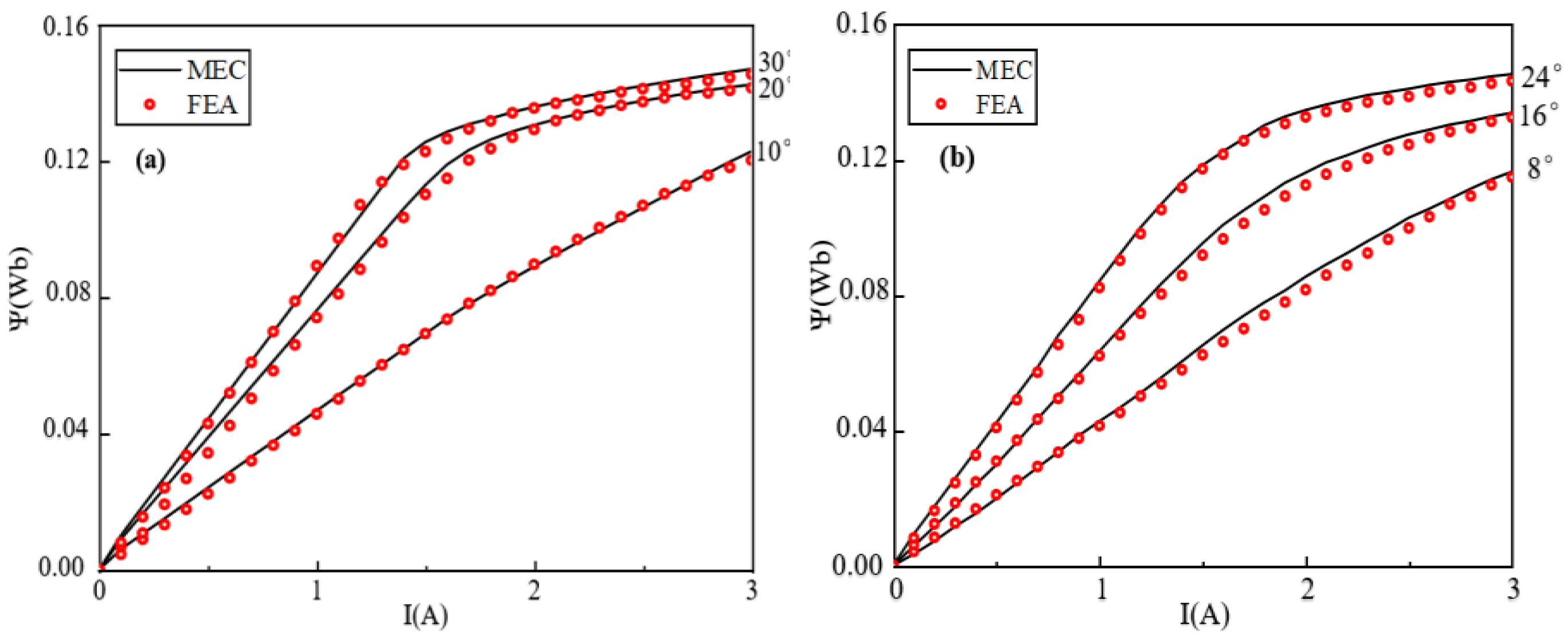
5. Verification of the Torque Model Based on MEC Method
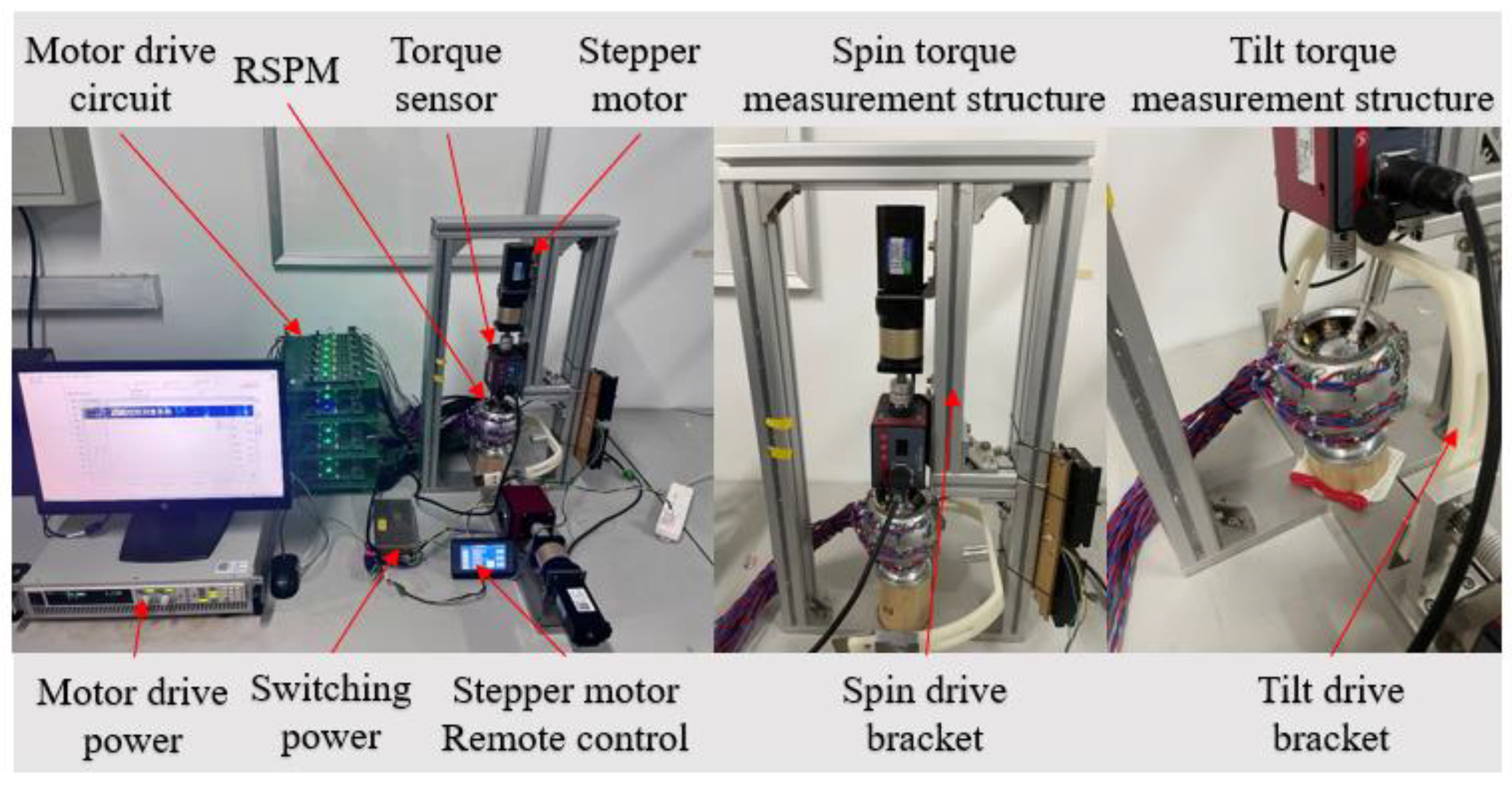
The experimental platform for torque measurement is shown in Figure 19, which includes a computer, motor drive power supply, motor drive circuit, RSPM, and torque measurement frame. The measurement process is as follows:
(1).
A pair of stator winding coils are energized by the motor drive circuits, and the rotor is locked.
(2).
The rotor is driven by a stepper motor at a speed of 3 r/min, and the motion control handle is used to control the forward and reverse rotation of the stepper motor.
(3).
The motion torque of the RSPM is measured through the torque sensor.
According to the conclusions drawn in the previous section, the magnetic and torque characteristics of the reluctance spherical motor are calculated based on the magnetic circuit topology when the stator and rotor poles are aligned, with verification conducted using three-dimensional finite element simulation. The magnetic characteristics refer to the single-phase flux linkage curves, which, like the torque curves, are functions of the rotor position and the phase current.
The results of the flux linkage curves and torque curves at multiple rotor positions, obtained from the equivalent magnetic circuit model, are shown in Figure 20 and Figure 21, with the current range being 0–3 A.
In terms of the trend and amplitude of the curves, the properties of the MEC torque model and the FEM simulation are consistent, which reflects that the analytical characterization method is reasonable and the results show the nonlinear properties of the RSPM. It reflects the changes of flux linkage and torque correctly and has a certain accuracy. As can be seen from Figure 21, the error is larger in the saturation region. It may be due to the fact that, in the equivalent process, the subdivision is not detailed enough and the effect of local saturation is not considered and the leakage magnetic flux is neglected. The main causes of errors in the experimental measurement of torque can be attributed to the following three factors:
(1)
Errors exist in the sensors during the rotor’s spinning and tilting motions.
(2)
Due to the supporting structure of the reluctance-type spherical motor, friction generated during rotor movement can also affect torque measurement.
(3)
The gravitational effect of the detection device may cause deviations in the torque measurement results.
In terms of the calculation speed of the model, the FEM simulation is affected by the computer configuration and the number of solution points whether from the early model establishment of the material configuration and mesh generation or the final iterative calculation. Under the relatively rough mesh generation, each solution point is at least a few minutes or more. However, the torque calculation model proposed in this study mainly focuses on the pretreatment of the equivalent model. Once the construction condition and calculation method of the MEC are determined, all flux linkage and torque values within the preset current range can be calculated in the order of seconds.

6. Conclusions

This paper studies the torque modeling method of the RSPM. The calculation results of the torque model based on the MEC method are basically consistent with those of the FEM simulation. At the same time, the calculation of torque model is much faster than that of the FEM simulation. This shows that the established model meets the requirements of fast torque calculation. Therefore, on the one hand, the proposed fast torque calculation model provides a necessary basis for the closed-loop control of the reluctance spherical motor. On the other hand, when optimizing the design of an RSPM with the torque as the goal, the fast torque calculation model can meet the needs of multiple iterative calculations of the optimization algorithm.
More importantly, this model considers the influence of the nonlinear characteristics of ferromagnetic materials on the torque, which is different from the linear torque model of a permanent magnet spherical motor. It provides a theoretical basis for the further research of the RSPM and has very important research significance.

Author Contributions

Methodology, L.J. and H.L.; Software, H.L. and K.Z.; Data curation, H.L.; Writing—original draft, H.L.; Writing—review & editing, G.L. and Q.W. All authors have read and agreed to the published version of the manuscript.

Funding

This work was supported by the Regional Innovation Joint Fund of the National Natural Science Foundation of China (U23A20647).

Data Availability Statement

Due to privacy and confidentiality agreements related to engineering design, detailed data supporting the results reported in this article, including schematics and related technical documents, cannot be made publicly available. Further inquiries can be directed to the corresponding author.

Conflicts of Interest

The authors declare no conflict of interest. The funding sponsors played no role in any of the following aspects: study design; data collection, analysis, or interpretation; manuscript composition; or the decision-making process for publication of the results.

References

  1. Tao, W.; Li, G.; Ju, L.; Zhou, R.; Hu, C. Design and analysis of a novel spherical motor based on the principle of reluctance. In Proceedings of the 2018 IEEE International Power Electronics and Application Conference and Exposition (PEAC), Shenzhen, China, 4–7 December 2018; pp. 1–6. [Google Scholar]
  2. Lee, K.M.; Pei, J.; Roth, R. Kinematic analysis of a three degree-of-freedom spherical wrist actuator. In Proceedings of the Fifth International Conference on Advanced Robotics ‘Robots in Unstructured Environments, Pisa, Italy, 19–22 June 1991; pp. 72–77. [Google Scholar]
  3. Lee, K.-M.; Wang, X.-A. Dynamic modeling and control of a Ball-Joint-Like variable-reluctance spherical motor. In Proceedings of the 1992 American Control Conference, Chicago, IL, USA, 24–26 June 1992; pp. 2463–2467. [Google Scholar]
  4. Lee, K.-M.; Sosseh, R.A.; Wei, Z. Effects of the torque model on the control of a VR spherical motor. Control Eng. Pract. 2004, 12, 1437–1449. [Google Scholar] [CrossRef]
  5. Chen, X.; Hu, J.; Chen, K.; Peng, Z. Modeling of electromagnetic torque considering saturation and magnetic field harmonics in permanent magnet synchronous motor for HEV. Simul. Model. Pract. Theory 2016, 66, 212–225. [Google Scholar] [CrossRef]
  6. Nakao, N.; Akatsu, K. A simple unipolar excitation strategy for switched reluctance motors by using PWM current control. In Proceedings of the 2013 IEEE ECCE Asia Downunder, Melbourne, VIC, Australia, 3–6 June 2013; pp. 1111–1117. [Google Scholar]
  7. Shao, J.; Deng, Z.; Gu, Y. Sensorless control for switched reluctance motor based on special position detection. ISA Trans. 2017, 70, 410–418. [Google Scholar] [CrossRef] [PubMed]
  8. Li, S.; Zhang, S.; Habetler, T.G.; Harley, R.G. Modeling, Design optimization, and Applications of switched reluctance machines—A Review. IEEE Trans. Ind. Appl. 2019, 55, 2660–2681. [Google Scholar] [CrossRef]
  9. Hou, J.; Geng, W.; Li, Q.; Zhang, Z. 3-D equivalent magnetic network modeling and FEA verification of a novel axial-flux hybrid-excitation in-wheel motor. IEEE Trans. Magn. 2021, 57, 8106912. [Google Scholar] [CrossRef]
  10. Li, H.; Zhao, Y.; Li, B.; Li, G.; Cui, L. Torque Calculation of permanent magnet spherical motor based on virtual work method. IEEE Trans. Ind. Electron. 2020, 67, 7736–7745. [Google Scholar] [CrossRef]
  11. Zhao, S.; Che, Y.; Li, H. Three-dimensional Interval Identification of Permanent Magnet Spherical Motor Based on Improved Deep Neural Network. J. Electr. Eng. Technol. 2024, 19, 419–431. [Google Scholar] [CrossRef]
  12. Shi, M.; Wang, Q.; Li, G.; Xu, J.; Han, Q.; Ye, Q. A new adaptive analytical model for the spherical reluctance motor based on hybrid trigonometric function-power function. IEEE Trans. Ind. Electron 2023, 70, 6099–6109. [Google Scholar] [CrossRef]
  13. Sun, X.; Xiong, Y.; Yao, M.; Tang, X. A hybrid control strategy for multimode switched reluctance motors. IEEE/ASME Trans. Mechatron. 2022, 27, 5605–5614. [Google Scholar] [CrossRef]
  14. Cai, Y.; Wang, Y.; Xu, H.; Sun, S.; Wang, C.; Sun, L. Research on rotor position model for switched reluctance motor using neural network. IEEE/ASME Trans. Mechatron. 2018, 23, 2762–2773. [Google Scholar]
  15. Chai, F.; Gan, L.; Pei, Y. Torque Characteristic of a Novel Tiered Type Permanent Magnet Spherical Motor. IEEE Trans. Ind. Appl. 2020, 56, 6338–6347. [Google Scholar] [CrossRef]
  16. Ostović, V. Dynamics of Saturated Electric Machines; Springer Nature: Dordrecht, The Netherlands, 1989; p. 107134341. [Google Scholar]
  17. Sudhoff, S.D.; Shane, G.M.; Suryanarayana, H. Magnetic-equivalent-circuit-based scaling laws for low-frequency magnetic devices. IEEE Trans. Energy Convers. 2013, 28, 746–755. [Google Scholar] [CrossRef]
  18. ManaaBarhoumi, E.; Wurtz, F.; Chillet, C.; Ben Salah, B. Reluctance network model for linear switched reluctance motor. In Proceedings of the 2015 IEEE 12th International Multi-Conference on Systems, Signals & Devices (SSD15), Mahdia, Tunisia, 16–19 March 2015; pp. 1–4. [Google Scholar]
  19. Ju, L.; Zha, K.; Wang, Q.; Li, G.; Zhou, R.; Wen, Y. A Torque Modeling Method of Spherical Reluctance Motor Based on the Magnetic Circuit Method. IEEE/ASME Trans. Mechatron. 2024, 1–9. [Google Scholar] [CrossRef]
  20. Shi, M.; Wang, Q.; Li, G.; Zhou, R.; Liu, Y.; Gao, S. A new analytical method for modelling of a spherical reluctance motor based on a small amount of measured flux linkage. Measurement 2023, 208, 112447. [Google Scholar] [CrossRef]
  21. Miller, T. Electronic Control of Switched Reluctance Machines; Elsevier: Amsterdam, The Netherlands, 2006. [Google Scholar]
  22. Sudhoff, S.D. Power Magnetic Devices: A Multi-Objective Design Approach; Elsevier: Amsterdam, The Netherlands, 2014. [Google Scholar]
  23. Vince, J. Quaternions for Computer Graphics; Springer: Berlin/Heidelberg, Germany, 2021. [Google Scholar]
Figure 1. The physical structure of the reluctance spherical motor (RSPM). (a) Motor assembly; (b) Stator layout; (c) Rotor layout and the coordinate system of the three degrees of freedom (3-DOF); (d) Simplified 3-DOF.
Energies 18 02882 g001
Figure 2. Yaw of the RSPM: (a) The rotor pole centerline aligned with the excited stator pole centerline; (c) The rotor pole centerline aligned with the stator slot centerline; (e) The rotor pole leading edge aligned with the excited stator pole leading edge; (b,d) Transition states; (f) Inductance profile.
Energies 18 02882 g002
Figure 3. Pitch of the RSPM: (a) The rotor pole centerline aligned with the excited stator pole centerline; (b) Transition process; (c) The rotor pole centerline aligned with the nonexcited stator pole centerline.
Energies 18 02882 g003
Figure 4. The location of the nodes.
Energies 18 02882 g004
Figure 5. Location of magnetic density observation lines.
Energies 18 02882 g005
Figure 6. Magnetic density variation on the air gap observation lines: (a) The magnetic flux density on observation line 1 varies with the angle of yaw, while the angle of pitch is 0°; (b) The magnetic flux density on observation line 1 varies with the angle of pitch, while the angle of yaw is 0°; (c) The magnetic flux density on observation line 2 varies with the angle of yaw, while the angle of pitch is 0°; (d) The magnetic flux density on observation line 2 varies with the angle of pitch, while the angle of yaw is 0°.
Energies 18 02882 g006
Figure 7. Flux tube model.
Energies 18 02882 g007
Figure 8. The reluctance network of the stator.
Energies 18 02882 g008
Figure 9. (a) The smallest unit equivalent flux tube of the stator spherical shell R suc ( Φ ) ; (b) R suc ( Φ ) is in the MEC.
Energies 18 02882 g009
Figure 10. (a) Stator pole reluctance flux tube; (b) Stator pole shoe reluctance flux tube.
Energies 18 02882 g010
Figure 11. (a) The equivalent flux tube division of the rotor yoke; (b) The equivalent flux tube division of the rotor pole; (c) R ruc ( Φ ) and R rtc ( Φ ) in MEC.
Energies 18 02882 g011
Figure 12. (a) The equivalent flux tube of the air gap R g ; (b) The reluctance network of the air gap with the fringe permeance.
Energies 18 02882 g012
Figure 13. (a) The fringe magnetic flux path; (b) The equivalent flux tube of the fringe magnetic flux.
Energies 18 02882 g013
Figure 14. The scale factor of the reluctance of the air gap.
Energies 18 02882 g014
Figure 15. The MEC of the RSPM (angel of yaw = 0°, angle of pitch = 0°).
Energies 18 02882 g015
Figure 16. The mesh analysis algorithm flowchart.
Energies 18 02882 g016
Figure 17. Standard branch.
Energies 18 02882 g017
Figure 18. The quaternion.
Energies 18 02882 g018
Figure 19. Torque experimental measurement platform.
Energies 18 02882 g019
Figure 20. Comparison between the calculated and the simulated flux linkage: (a) yaw motion; (b) pitch motion.
Energies 18 02882 g020
Figure 21. Torque comparison at different angles: (a) yaw motion 10°; (b) yaw motion 20°; (c) pitch motion 8°; (d) pitch motion 16°.
Energies 18 02882 g021
Table 1. Stator pole labels.
Upper polesE1F1G1H1I1J1K1L1
Middle polesA1B1C1D1A2B2C2D2
Lower polesI2J2K2L2E2F2G2H2
Table 2. Partial Parameters of the Magnetic Flux Tube Model.
ParametersValue (mm)ParametersValue (mm)
wo45.95l210
wd7l314
w115l416
w22l59
ws12w312.1
wg1w420.42
l1102.11
Disclaimer/Publisher’s Note: The statements, opinions and data contained in all publications are solely those of the individual author(s) and contributor(s) and not of MDPI and/or the editor(s). MDPI and/or the editor(s) disclaim responsibility for any injury to people or property resulting from any ideas, methods, instructions or products referred to in the content.

