1. Introduction
The permanent magnet synchronous motor (PMSM) has been used in a wide range of various industry applications and has drawn a lot of attention due to its compact structure, excellent efficiency, superior power density, and comparatively high overload capability [
1,
2]. Compared to the conventional PMSM, some PMSMs with novel topologies have been designed and investigated [
3,
4,
5]. These novel topological motors include the radial-flux or the axial-flux permanent magnet motors, which can also be categorized into single-stator double-rotor structure, double-stator single-rotor structure, and multi-stator multi-rotor structure [
6]. Among these three different structures of motors, the single-stator dual-rotor permanent magnet motor is more suitable for powering underwater vehicles (UVs) or aerial vehicles due to its smaller size, lower noise, and lower vibration [
7].
In general, a PMSM with twin rotating rotors has a single-stator topology with two rotors and can be analyzed as two traditional PMSMs with a single-stator single-rotor topology connected in parallel or series [
8,
9]. It is worth noting that this type of motor is actually an axial PMSM with dual-rotating rotors, which is mainly composed of one stator and two rotors, and all of them have a disk form. This form can reduce the length of the coil at both ends and fully use the stator windings, making the motor more compact and reducing the heating loss of the coil, which has the advantage of high torque density and an axially compact form factor [
10]. The PMSM with dual-rotating rotors machine is characterized by an axial flux path between the rotor and the stator. This type of motor can fully use the stator windings and generate two relatively independent rotating magnetic fields that can drive both rotors to rotate and provide power [
11,
12]. In practical applications, the speeds of both rotors must be synchronized in order to prevent the UV or aerial vehicle from rolling. For the traditional PMSM with a single-stator single-rotor topology, it is relatively simple to control the rotor so that it follows the rotation of the stator magnetic field. For the dual-rotor PMSM, how to keep both rotors rotating simultaneously has attracted the researchers’ attention around the world.
A common approach to simplifying PMSM regulation is to use the field-orientation strategy to control motor operation. This technology can simply implement the torque control as a DC motor, but there is a disadvantage that the control strategy can not deal with the typical nonlinear and strong coupling system. Additionally, the dynamic performance is sometimes poor [
13]. Many nonlinear control strategies, for example, intelligent control [
14], sliding mode control (SMC) [
15], model predictive control [
16], neural control [
17], self-learning technology [
18], and others, have been proposed by developers in recent decades to enhance the operating dynamics of the drive system. Utkin [
19,
20], Drakunov [
21], and Loukianov [
22,
23] proposed their respective SMC methods and designed the controller, and they also confirmed the feasibility and effectiveness of the proposed control algorithms through simulation and experiments. Loukianov [
23] described the model of the fuzzy controller and designed a multistage fuzzy controller for a multi-motor system. It should be noted that the nonlinear control algorithms mentioned are currently popular methods, and all of them have advantages and disadvantages. The SMC is insensitive to disturbances and parameters, which has its advantages in dealing with uncertainty and external disturbances. Similarly, to verify that the PMSM with multi-rotor operates stably, various strategies are also applied to control its operation. In order to control the synchronous operation of both permanent magnet motors connected in parallel, Chiasson et al. [
24] proposed a method to control each motor’s quadrature current, and experimental results showed that the method was effective. Cheng and Luo et al. [
11] analyzed the instability of the motor system for the motor system with dual counter-rotating rotors under the condition of an unbalanced load, and Zhong et al. [
12] discussed three situations:
TL1 =
TL2,
TL1 >
TL2, and
TL1 <
TL2 for the motor system with dual rotors, and the master-slave control method to select the master motor, and then the SMC method to make sure the synchronous operation of the dual rotors.
Although the stable operation solutions of a motor system were discussed in [
11,
12,
24], it’s tough to accurately operate the rotation speed of a motor drive system in actual situations due to system parameter changes and external disturbances. Some comprehensive techniques for control, involving the disturbance estimation approach and SMC control, have been implemented in the drive system to correct these shortcomings. The disturbance estimation technique can calculate the drive system’s lump disturbances, including some internal parameters and external disturbances, and it has been widely used in robust control or adaptive control. But the observers designed in [
25,
26] are only used for those matched lump disturbances of the motor system, and the SMC control can lose the property of invariance when there are lots of unmatched uncertainties. In order to solve these nonlinear problems, some researchers proposed a nonlinear disturbance observer control technology for the unmatched uncertainties. Mou et al. [
27] used a disturbance observer to control uncertain nonlinear systems with unknown hysteresis. Liu X.D. and Shi T.N. in [
28,
29] also used a disturbance observer to control a nonlinear PMSM system and achieve good robustness performance.
Compared with the traditional PI control, the SMC has the advantage of being insensitive to disturbances and parameters. As mentioned in the literature [
15,
19,
20,
21,
22,
23], the SMC is used to control the single stator and single rotor motor system. In this research, it is considered a new attempt in which the SMC method is used to control the PMSM with a dual-rotating rotor system. In this article, a linearization theory is used to analyze the motor system and design an SMC controller to replace the traditional voltage and current feedback control, taking into account the complexity of the motor system. To estimate lump disturbances, a nonlinear disturbance observer that takes into account motor system parameter variations as well as external disturbances is proposed. The transient response and robustness of the motor drive system can be enhanced by using the observed values in the SMC controller.
This work can be summarized as follows. As a starting point,
Section 2 provides an overview of the PMSM with dual-rotating rotors’ three-dimensional (3D) structure and operation.
Section 3 introduces and designs the SMC controller and disturbance observer. Some simulations and experimental results demonstrate that the proposed method is effective in
Section 4. Finally,
Section 5 presents the conclusion of this paper.
2. Model and Operation of the Motor
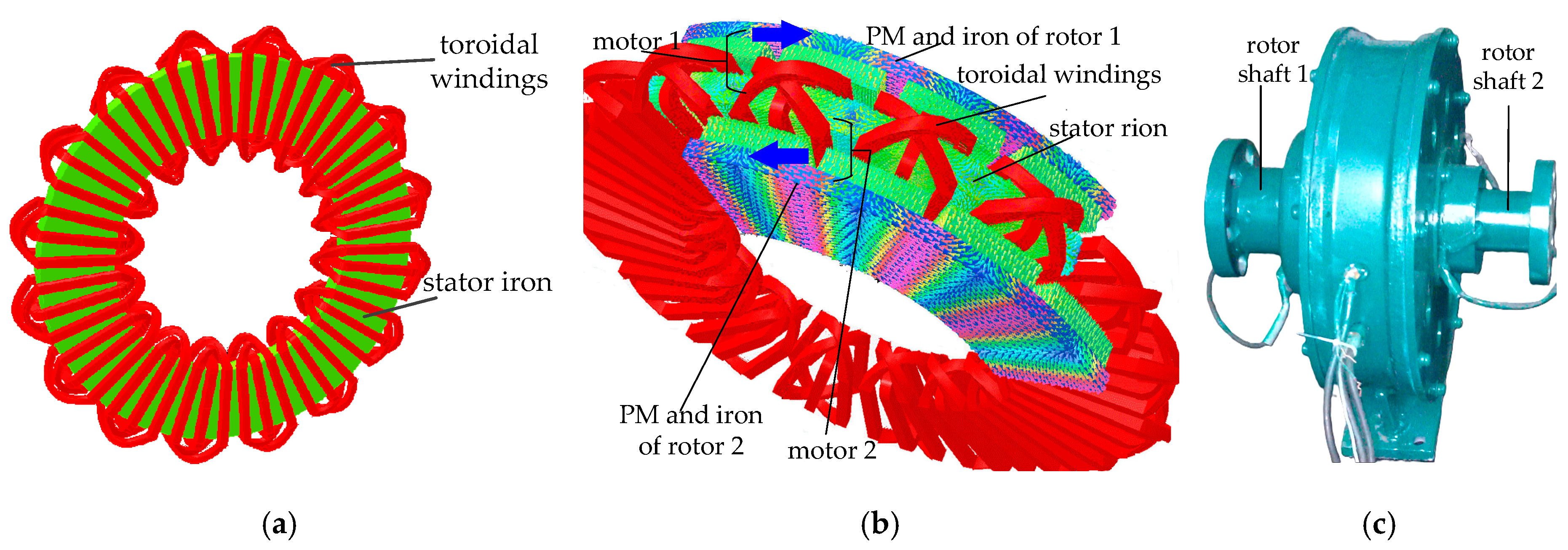
Figure 1 shows the motor model and its prototype. It is worth noting that this proposed motor is an axial motor. Both sides of the stator are distributed with toroidal windings in
Figure 1a, and the purpose of this structure is to make the motor fully use the windings and improve efficiency compared with traditional motors. As shown in
Figure 1b, the motor can be thought of as two conventional permanent magnet (PM) motors connected in series through a stator winding, which are referred to as motors 1 and 2. As shown in
Figure 1b, the motor 1 consists of the PM and iron rotor 1 and half of the torroidal windings. The same applies to motor 2. For the convenience of explanation, the names of both rotors are the same as the motor’s names, namely rotor 1 and rotor 2. Since the stator windings are fully utilized, the motor with the new topological structure will have better efficiency. For the traditional permanent magnet synchronous motor with a single stator and single rotor, the speed can be controlled by information such as voltage, current, and rotor position. In order to ensure that both rotors rotate at the same speed, it is necessary to detect the position information of both rotors and then quickly select motor 1 or motor 2 as the master motor and the other motor as the slave motor for the proposed motor.
In order to provide both rotors with opposing rotational direction, we can change the phase order of the torroidal windings (e.g., phase B and phase C). When the toroidal windings are supplied with three-phase currents, a magnetic field that rotates in opposing directions may form at either side of the stator. So the PM flux can separately interact with the respective rotating magnetic field and obtain the opposite electromagnetic torque, and it may result in both rotors running in an opposing direction [
4,
11,
12]. The motor prototype with dual-rotating rotors is illustrated in
Figure 1c.
For the traditional permanent magnet synchronous motor with a single stator and single rotor, the speed can be controlled by information such as voltage, current, and rotor position. In order to ensure that both rotors rotate at the same speed, it is necessary to detect the position information of both rotors and then quickly select one motor as the master motor and the other motor as the slave motor for the proposed dual-rotor permanent magnet synchronous motor.
3. Algebraic Modeling and Control Methods
In this segment, some preliminary information is outlined so as to clarify the presented control scheme, including the mathematical model of the motor, the design of an SMC speed controller, and a disturbance observer.
3.1. Algebraic Model of the Motor
According to field-oriented theory, it is essential to present a dq1 synchronous reference coordinate for motor 1 and a dq2 for motor 2 accordingly. As mentioned in [
9,
10,
11,
12], the dq1 and dq2 coordinate frames have the same direction of rotation, so that both rotating rotors can be analyzed in a uniform dq synchronous reference frame.
For analytical convenience, it is assumed that the magnetic circuit remains unsaturated and the magnetic field remains sinusoidal without eddy current losses and hysteresis. Considering that the stator windings are connected in series, the proposed motor’s mathematical model in the dq reference system is given by [
12]:
where
ω1 and
ω2, respectively, represent the electrical angular speeds of rotors 1 and 2, the d-axis and q-axis stator voltages are ud and uq, the stator resistance is Rs, the dq-axis stator inductances are
Ld and
Lq (satisfying
Ld =
Lq =
L), and
Ψ is the permanent magnet flux linkage. For the convenience of subsequent simulations and experiments, the speed
n(r/min) and angular velocity of the motor
ω(rad/s) satisfy
ω = 2π
n/60.
When
is introduced, the mechanical equation of the proposed motor can be described as:
where
B is the coefficient of viscous friction,
is the number of pole pairs, and
is the moment of inertia.
It should be emphasized that it is a challenge to obtain accurate electrical and mechanical values in the Equations (1)–(4) because of the fact that these values should fluctuate based on the operating factors such as temperature and losses [
13]. Moreover, the load torques on both rotors would vary under the condition of a turbulent environment. Therefore,
,
,
and
in the Equations (1)–(4) are used to indicate these disturbances caused by the change of the parameters or load torques, and they can be given as follows:
There is , , , , , in Equations (5)–(7), where , , , , , indicate actual values of the respective parameters and , , , , , indicate the rated parameter values. and represent the electrical angular speed and the load torque. It should be mentioned that the index i = 1 or i = 2 denotes whether the parameter represents the corresponding motor 1 or 2. It is well known that the variables of the traditional PMSM are strongly influenced by temperature. For the mentioned motor, the affections are similar to those of traditional PMSM. As a result, the internal component deviations always fluctuate within a certain limit. In practice, the load torque should also be changed within a specified range of its rated value. So these disturbances (, , ) and their derivatives would be limited in scope.
3.2. The Proposed Control Strategy
The following mainly introduces the suggested strategy of control for the mentioned drive system. Different from the conventional double closed-loop control of voltage and current, where the speed or current is, respectively, controlled by the same or different control strategy, the designed controller can simultaneously control the current and speed by SMC. To some extent, this proposed controller integrates two traditional closed-loop controllers, and its goal is to identify the best control output to realize the current and speed tracking regulation.
3.2.1. Linearization Model for PMSM with Dual-Rotating Rotors
As suggested in [
12], a master-slave control technology can be used to choose which motor will serve as the master motor. Once motor 1 is selected as the master motor, motor 2 is the slave one. Thus, the motor 1 model, which is composed of Equations (1)–(3), can be looked on as a nonlinear system with the output variable
y = (
y1 y2)
T = (
id ω1)
T, the input variable
u = (
ud uq)
T, the state variable
x = (
x1 x2 x3)
T = (
id iq ω1)
T, and the disturbance variable
d = (
fd fq fω1)
T. Similarly, when motor 2 is the master one, the model of motor 2 composed of Equations (1), (2), and (4) can likewise be regarded as another nonlinear system with the output variable
y = (
y1 y2)
T = (
id ω2)
T, the input variable
u = (
ud uq)
T, the state variable
x = (
x1 x2 x3)
T = (
id iq ω2)
T, and the disturbance variable
d = (
fd fq fω2)
T.
For simplicity, these two nonlinear equations can be unified into one new nonlinear state-space equation with
u = (
ud uq)
T,
x = (
x1 x2 x3)
T = (
id iq ωi)
T = (
id iq ω)
T,
y = (
y1 y2)
T = (
id ωi)
T = (
id ω)
T and
d = (
fd fq fωi)
T = (
fd fq fω)
T, where
ωi =
ω and the index
i = 1 or 2 means motor 1 or 2 is used as the master motor and
ωi corresponds to the speed of motor 1 or 2 [
30].
According to the feedback linearization principle and method, the linear differential relationship between the input u(t) and output y(t) can be given as:
For simplification, we can rearrange Equations (8) and (10). Defining
,
,
,
and
, then the Equations (8) and (10) can be shown as:
Meanwhile, defining
and
as the intermediate variables and
, the Equations (11) and (12) can be rewritten as the following expression:
By transformation, the Equation (13) can be derived as follows:
As a result, Equation (14) can be deduced and chosen as the controller law of the PMSM drive system with dual-rotating rotors. It is evident that these outputs u = (ud uq)T in (14) are the input voltages for the SVPWM module. Obviously, the controller designed on the basis of the feedback linearization method is sensitive to these parameters of the motor system.
3.2.2. Terminal Sliding Mode Control Algorithm for the Motor System
A suggested control algorithm is introduced to minimize the impact of intermediary variables within the regulator described by Equation (14). As a result, the current of the d-axis can be controlled by a sliding mode control algorithm, where
is defined. In this work, the traditional field of oriental control
is adopted. In order to achieve better tracking precision and faster convergence ability, a typical nonsingular terminal sliding mode surface can be selected as below [
31]:
where
and
is the reference d-axes current,
. For
and
in (15), they are positive odd integers and satisfy
.
The expression
is chosen for the intermediate variable
, in which there is
. Substituting into (8), the following is a description of an equation for the controller’s output
using the terminal sliding mode control technique:
The following inequality can be obtained by using a Lyapunov function
in accordance with the Lyapunov stability condition.
It can be concluded from expression (17) that the d-axis current error can reach convergence within a certain time, which satisfies the sliding-mode reaching condition. As a consequence, the controller designed for this motor system is reliable and stable.
Similarly, the speed error
is defined. It is worth mentioning that only the actual speed
of the master motor is taken as the operation parameter to participate in the calculation of the speed error
. The speed error’s (
) second-order differential expression is as follows:
According to Equation (13), by substituting
into (18), the
expression can be rewritten and changed as follows:
In order to achieve better speed tracking performance, the selection of an additional nonsingular terminal sliding mode surface is as follows:
There is in (20). For and in (20), they are all positive odd integers and guarantee .
The expression
is chosen for the intermediate variable
, in which there is
. Because there is
,
can be derived when the change of the reference speed
is ignored. Substituting
into (19), an equation of the output
of the regulator that adopts the technique of terminal sliding mode control can be described as follows:
Considering the Lyapunov stability condition, a Lyapunov function
is available, and a subsequent contradiction can be easily achieved as follows:
It can be concluded from (22) that the speed error can converge at a definite time, which matches the sliding-mode reaching criteria. Therefore, the designed control is stable.
However, there are uncertainties fd, fq and fω about the proposed motor drive system in the above-mentioned controller. Those mismatched uncertainties in (16) or (21) are negative factors for the motor drive system. To further improve the overall dependability of the motor drive system and achieve higher performance, it is vital to eliminate these negative effects from unpredictable disturbances.
3.2.3. Disturbance Observer for the Motor Drive System
It’s well known that an actual motor system has nonlinear characteristics that are susceptible to those internal variations and unknown external disturbances. A disturbance observer that utilizes and estimates the lump perturbation is designed for the feed-forward compensatory regulation [
32,
33,
34,
35].
To facilitate the disturbance observer design, the mechanical Equations (3) (for motor 1) and (4) (for motor 2) can be unified as follows:
where
,
is the speed of motor, and the symbol
or
denotes that motor 1 or 2 is the master motor.
Hence, the proposed motor’s model can be outlined by the expressions (1), (2), and (23). According to (1), (2), and (23), the following expressions can be defined as follows:
Invoking (24) and (25), a disturbance observer as shown below could be formed for the mentioned drive system:
where
λ(
x) denotes a nonlinear function and
denotes the internal state variables for the disturbance observer. In (26),
u = (
ud uq)
T represents the input variable,
represents the estimation of all unknown disturbances,
denotes the observer’s gain function.
To further illustrate the observer shown in (26), a disturbance estimator
which satisfies the following relationship is introduced.
The subsequent candidate for the selection of the Lyapunov function is as follows:
According to (17), (22) and (27), the derivative of
in (28) has the subsequent relationship:
From (29), it can be seen that the (estimation of disturbance) can converge at a specific time and the motor system exhibits asymptotic stability. Therefore, the regulator designed through the sliding model control and disturbance observation technology is feasible. Moreover, the proposed control strategies can implement the control of speed tracking.
4. Results of Simulation and Experimentation
The proposed control technique will be validated through simulation in
Section 4.1 and experimentation in
Section 4.2. By comparing the results under the proposed control scheme with those of the PI (proportional-integral) control scheme, some obvious conclusions validating the effectiveness are obtained. The overall block diagram of the drive system is shown in
Figure 2. The overall system consists of the PMSM motor, a set of SVPWM inverters, a position and speed calculation module, a position comparator module, and a proposed controller. The angular positions of both rotors are compared through the position comparator, and then a selection signal will be generated. According to the selection signal, the controller selects the electrical angular speed of rotor 1 or rotor 2 and its corresponding angular position.
The proposed controller uses the inputs, such as
(the reference speed),
(there is
in the work),
, and
. The position and speed calculation and position comparator essentially achieves the decision of the master motor, and then uses the position
and speed
of the master motor to participate in the calculation of the suggested control approach. Moreover,
Figure 3 shows the experimental platform of the motor drive system. And
Figure 3a shows the overview of the experimental platform, and
Figure 3b shows the overview of the proposed motor type and load generators. The motor’s nominal parameters are shown in
Table 1. These two load generators are both induction motors with the same parameters. The parameters of the induction motor are shown in
Table 2.
In the simulation and experimentation, when the PI control scheme is adopted, the parameters of the speed controller and the current controller are
kp = 11.5 and
ki = 3.2. When the proposed control is adopted, the parameters of the terminal sliding mode are
,
,
and
,
. For improving the response speed and decreasing the chatting, the absolute value of the speed error (
) is taken into account when choosing the variable parameter
. In
Figure 4,
is the absolute value of the speed error,
is the given comparison value,
, and
is the corresponding coefficient changing with
ni,
.
4.1. Simulation
The MATLAB 2020b software has been used to create a simulation model and explore the suggested method of control. The proposed SMC approach and disturbance observation technique are utilized to control the two rotors running synchronously. The loads of both rotors are changed during the simulation in order to simulate the actual operating conditions as closely as possible, and the performance of the experimental motor system is simulated. In
Figure 5, the response waveforms of the motor drive system are illustrated. It can be found that the loads of both rotors are changed simultaneously from 5 Nm to 10 Nm at t = 0.8 s. Both speed waveforms all have a slight decrease at 0.8 s, and the overshoot of the speed controlled by the suggested control strategy is smaller than that of the PI approach, as illustrated in
Figure 5e. During the whole simulation process, the current of phase A changes smoothly in a sinusoidal form, and its amplitude also increases at 0.8 s due to the increase in both loads. The given speed for the experimental motor drive system is 600 r/min. The response waveforms are indicated in
Figure 5, which are precisely controlled by the presented control approach. Moreover,
Figure 5c demonstrates that the current of the d-axis
id is zero during the simulation, which indicates that the control strategy of
id = 0 is likewise well achieved. The simulation findings reveal that the effectiveness of the suggested control is superior to that of the standard PI control, which further shows that the proposed control algorithm improves both robustness and control performance.
4.2. Experimentation
Additionally, an experimental bench is also used to validate and implement the proposed control scheme. The motor’s nominal parameters are shown in
Table 1.
Figure 3, mentioned before, depicts the whole experimental bench, which consists primarily of the experimental prototype, two consoles of load generator, a DSP TMS320F28335 (Digital Signal Processing) microprocessor control unit coded in the CCS (Code Composer System) environment, and display and detection units. The DSP control circuit module in the CCS environment uses the C++14 language to program the aforementioned algorithms and control the speed of the motor drive system. The PMSM with dual-rotating rotors is powered by a controlled three-phase power supply, and both rotors are, respectively, connected to an AC motor used as a load generator through a torque transducer.
The experimental bench is used to regulate the operation of the prototype using both the conventional PI control and the proposed SMC strategy. Moreover,
Figure 6 shows the dq-axis experimental current waveforms under equivalent load torque conditions (
Tl1 =
Tl2 = 5 Nm). In
Figure 6a, the q-axis current is about
iqmax = 4.6 A and
iqmin = 3.4 A. Compared to the current
iq = 4 A, it can be seen that the q-axis current fluctuation is about
under conventional PI control. In
Figure 6b, the q-axis current is about
iqmax = 4.3 A and
iqmin = 3.7 A. Compared to the current
iq = 4 A, the current fluctuation is about
under the proposed control. The same situation also occurs with the d-axis current, the current fluctuations are 0.6 A or 0.3 A, respectively. Consequently, the recommended control approach reduces dq-axis current fluctuation and improves the system’s robustness.
The operation of both rotors is similarly verified under unbalanced loads, where rotor 1’s load torque is 10 Nm (
Tl1 = 10 Nm) and rotor 2’s load torque is 8 Nm (
Tl2 = 8 Nm). Experiments are carried out to evaluate whether the suggested control is effective.
TL1 and
TL2 in this paper refer to the load torque. When the motor runs stably, its electromagnetic torque (
Te) should be equal to the load torque (
TL). In
Figure 7 and
Figure 8,
TL1 and
TL2 are used to indicate the output electromagnetic torque on the two rotors of the motor. The traditional PI control is also used to control the motor drive system under the same conditions, and the speed waveforms of both rotors are obtained.
Figure 7 shows that in the case of unbalanced loads, both rotors 1 and 2 can rotate at the rated speed n = 600 r/min regardless of whether the conventional PI control approach or the proposed control approach is used. In
Figure 7a, the speed changes from about 640 r/min to 560 r/min. Compared to the given speed of 600 r/min, the speed fluctuation is about 40 r/min under conventional PI control. In
Figure 7b, the speed varies from about 610 r/min to 590 r/min. Compared to the given speed of 600 r/min, the speed fluctuation is about 10 r/min under the proposed control. From
Figure 7a,b, it can be seen that the speed fluctuation of both rotors controlled by the conventional PI scheme is greater than that of both rotors controlled by the proposed control strategy. According to the results, the proposed control technique can more precisely regulate the speed of both rotors when the load torques are not balanced, which is beneficial for lowering system fluctuations and enhancing control precision.
During the test, the given speed is adjusted from 600 r/min to 250 r/min and then back to 600 r/min to study the system’s dynamic performance, while both rotors’ load torques are fixed at 10 Nm.
Figure 8a,b compare the test findings between the typical PI control strategy and the proposed control scheme. In
Figure 8a, the speed changes from about 640 r/min to 560 r/min when the given speed is 600 r/min. Meanwhile, the speed varies from 285 r/min to 210 r/min when the given speed is 250 r/min. It can be seen that the speed fluctuation is about 40 r/min under conventional PI control. In
Figure 8b, the speed changes from about 610 r/min to 590 r/min when the given speed is 600 r/min. And then the speed varies from 262 r/min to 240 r/min when the given speed is 250 r/min. The speed fluctuation is about 10 r/min under the proposed control. These results indicate the proposed control scheme has a lower speed change than the conventional control strategy (about 10 r/min versus about 40 r/min), implying that the recommended control method has a better influence on the motor system’s dynamic stability as well as its disturbance suppression capabilities.
Figure 8 depicts the motor driving system’s dynamic processes, and the disturbance suppression capabilities have improved using the proposed control strategy. As a result, the proposed control strategy can be used to control the motor system in the synchronous rotation mode.


