1. Introduction
Energy harvesting is the process of obtaining electrical energy from the environment. For this purpose, various mechanisms are used to convert, e.g., mechanical energy, solar radiation, wind momentum, electromagnetic field energy, into electrical energy. The reduction in the size of microcontrollers and their energy requirements makes efficient energy management an important requirement for wireless sensor networks (WSN) and Internet of Things (IoT) elements [
1,
2].
In this article, we presented a study on energy harvesting from a time-varying magnetic field. Focusing on this area, several methods were identified. The first method uses a magnetic induction. In its simplest configuration, a ferromagnetic core with a wound coil was placed around a current-carrying conductor. To achieve high efficiency, it was necessary to close the magnetic flux path, which typically required a closed magnetic circuit encompassing the entire conductor. However, such a configuration often poses challenges in terms of mechanical assembly. Depending on the core material, its dimensions, geometry, the number of coil turns, and the amplitude of the current, it was possible to harvest power on the order of several watts [
3,
4,
5].
The second method relied on an electromechanical generator with permanent magnets. An example of such a harvester was presented in [
6], where the authors attached alternating-polarity permanent magnets to a flexible cantilever beam integrated with a winding, positioned near an AC power line. Vibrations of the beam, induced by the interaction between the magnetic field of the line and the permanent magnets, resulted in relative motion between the coil and the magnetic field, which in turn induced voltage. The system was capable of harvesting power in the range of 160 μW. A similar mechanism was also employed in [
7,
8].
The third method utilized a magneto-mechanical-electric (MME) harvester with piezoelectric elements. According to the current state of knowledge, piezoelectric elements subjected to oscillations, which are produced by a permanent magnet vibrating in a magnetic field from a current-carrying conductor, can be used to convert the energy of the magnetic field around the conductor into electrical energy [
9,
10,
11]. A permanent magnet placed in a variable magnetic field performs oscillatory movements, counteracting the magnetic field from the current-carrying conductor, according to Lenz’s rule. The electrical powers that can be obtained from such systems are up to 10.7 mW [
12]. The most commonly used piezoelectric elements are ceramic materials such as zinc oxide (ZnO), lead zirconate titanate PZT (PbZrO
3 and PbTiO
3), and barium titanate, as well as polymeric materials such as polyvinylidene fluoride PVDF [
13,
14] and BCTZC composites [
15].
The fourth method involves magnetoelectric and magnetostrictive composites (MME), in which a magnetostrictive material (e.g., Galfenol or Terfenol-D alloy) is bonded to a piezoelectric layer. In such systems, a time-varying magnetic field induces deformation in the magnetostrictive layer, which is mechanically transferred to the piezoelectric layer, thereby generating an electrical voltage. This mechanism enables MME composites to directly convert even weak ambient magnetic fields into electrical energy [
16,
17]. Pattipaka et al. report that modern MME devices are capable of converting ambient magnetic fields into electrical signals with power exceeding 50 mW [
18].
Although significant progress has been made in energy harvesting technologies, most existing solutions have limitations when applied to environments with strong alternating magnetic fields—such as near power lines or industrial equipment. Magnetic induction-based harvesters, while effective, require bulky magnetic cores and closed-loop assemblies, which are difficult to integrate with miniaturized systems. Electromechanical solutions offer reduced complexity but often suffer from low efficiency and frequency mismatch. Magnetostrictive–piezoelectric composites can be highly sensitive but are still expensive and mechanically fragile.
Moreover, most previous studies focus on power levels, or fabrication techniques, while relatively few works analyze how structural design parameters (such as geometry, and layer configuration) affect the energy harvesting performance of piezoelectric resonators under s AC magnetic fields. In this context, our research focuses on a PZT-based MME harvester excited by a 50 Hz alternating magnetic field. The main goal is to evaluate the impact of the resonator structure—single layer versus bimorph—on the system’s energy conversion efficiency.
This work indicates that not only can piezoelectric materials such as PZT be effectively used for magnetic field energy harvesting, but also that a bimorph configuration can improve performance by over two orders of magnitude compared to a single-layer structure. Such results are relevant for practical applications in smart grids, self-powered sensors, and embedded monitoring systems in environments with strong AC electromagnetic fields. The article is organized as follows. After an introduction to the subject in
Section 1,
Section 2 presents a formal analysis and simulation results related to energy harvesting using a piezoelectric harvester in both unimorph and bimorph structures. In
Section 3, we present and discuss the results of experiments conducted under laboratory conditions.
Section 4 provides a discussion and comparison of the obtained results with available scientific studies.
Section 5 contains the summary of the article.
2. Piezoelectric Beams
Piezoelectric energy harvesters utilizing magnetic fields offer a promising solution for powering small electronic devices in environments where conventional power sources are unavailable, such as sensors operating in high-voltage or hazardous areas. These devices convert mechanical vibrations into electrical energy, making them suitable for applications including wireless sensor networks, structural health monitoring systems, and remote sensing. One of their key advantages is that they do not require direct contact with the monitored object, enabling energy harvesting from electrical currents in conductors or rotating machinery. Furthermore, they can be integrated into industrial equipment to recover energy from power transmission lines, thereby reducing the need for battery replacement in remote or difficult-to-access locations. Their compact size, robustness, and ability to operate in harsh environments make them an attractive option for sustainable and maintenance-free energy solutions.
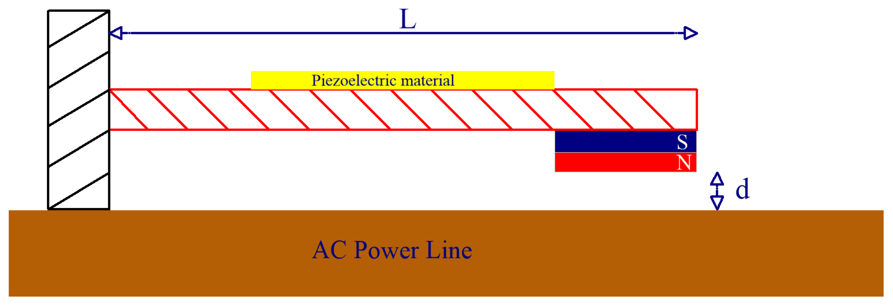
In the presented case study, electromagnetic energy is extracted from the alternating magnetic field surrounding a busbar carrying currents of 10–130 A at a frequency of 50 Hz. A flat rectangular copper bar of dimensions 40 mm × 5 mm—one of the most popular busbar sizes in medium-voltage switchboards and distribution boards—was deliberately selected so that the harvester could be installed directly on or attached to standard busbars without any modifications to existing equipment. Two types of vibrating beam harvesters were tested: one with a single piezoelectric layer, shown in
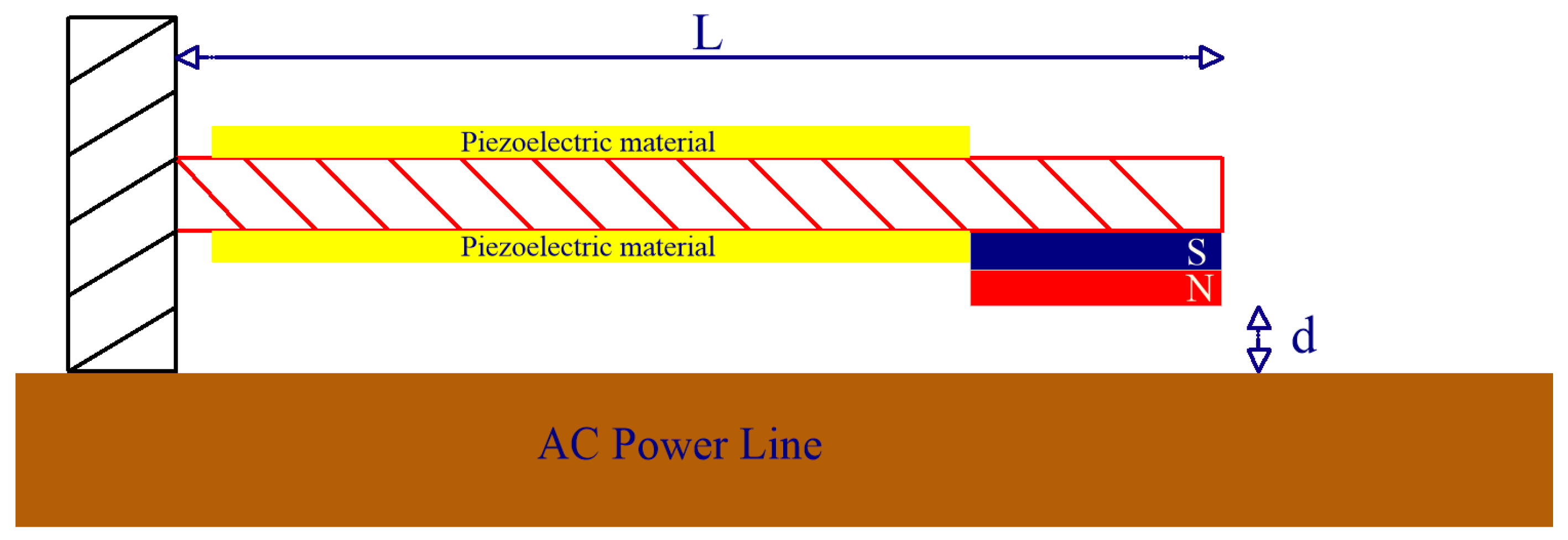
Figure 1, and another with a bimorph configuration consisting of two piezoelectric layers, shown in
Figure 2. The bimorph arrangement features two piezoelectric transducers connected in series and separated by a brass shim. The piezoelectric elements are arranged so that their deformations are always in opposite directions—when one layer expands, the other contracts—resulting in a higher overall deformation energy compared to a single-layer configuration [
19].
The above diagrams show a vibrating beam with a piezoelectric element and a permanent magnet attached. The beam is cantilevered, which allows one of its ends to be played. For a single-layer beam, a piezoelectric material is mounted on the top surface of the beam to convert mechanical vibrations into electrical energy. A permanent magnet is attached to the free end of the beam, acting as a vibrating mass. The magnet is placed over a rectangular conductor carrying an electric current. The current in the conductor generates an electromagnetic field that interacts with the magnet, inducing vibrations. These vibrations are transferred to the beam and converted into electrical energy by the piezoelectric element. A piezoelectric transducer made of PZT material in the shape of a cylinder with a diameter of 25 mm and a height 1.2 mm is used in the single-layer beam. The bimorph beam is made of two rectangular layers of PZT ceramics, with dimensions of 60 × 30 mm and thickness of 175 µm, which were attached to a 210 µm thick copper plate constituting the arm of the vibrating beam, the transducer parameters are shown in
Table 1. The PZT material was selected due to its high piezoelectric strain coefficient D
33 = 670 pC/N and a high electromechanical coupling factor k
33 = 0.6. These parameters are more favorable than those of PVDF and comparable to BCTZC. However, the availability of PZT is significantly higher.
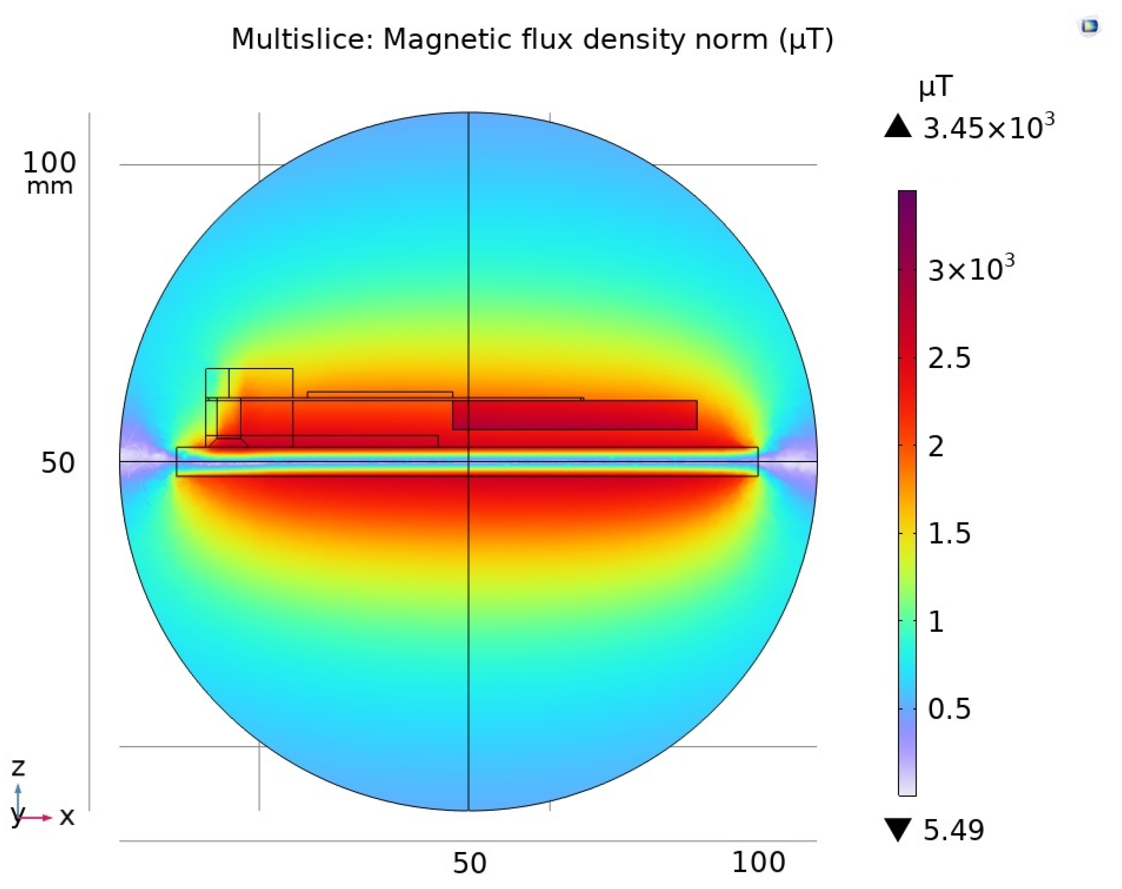
The magnetic field distribution around the conductor was simulated using COMSOL Multiphysic 6.3 software is shown in
Figure 3a,b. Both perpendicular and parallel orientations of the bar magnet with respect to the conductor were analyzed. The aim of the simulations was to determine the optimal position of the magnet that would result in the strongest interaction with the external magnetic field. In each case, it was assumed that the magnet was positioned 3 mm away from the current-carrying conductor. The bar magnet used in the simulation had dimensions of 42 × 20 × 5 mm.
Additionally, a plot of the magnetic field distribution along the
Z-axis around the current-carrying conductor was generated to illustrate the relationship between the magnetic field strength and the distance from the conductor.
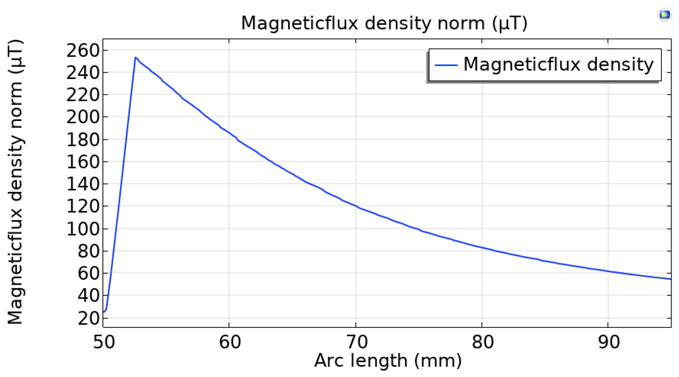
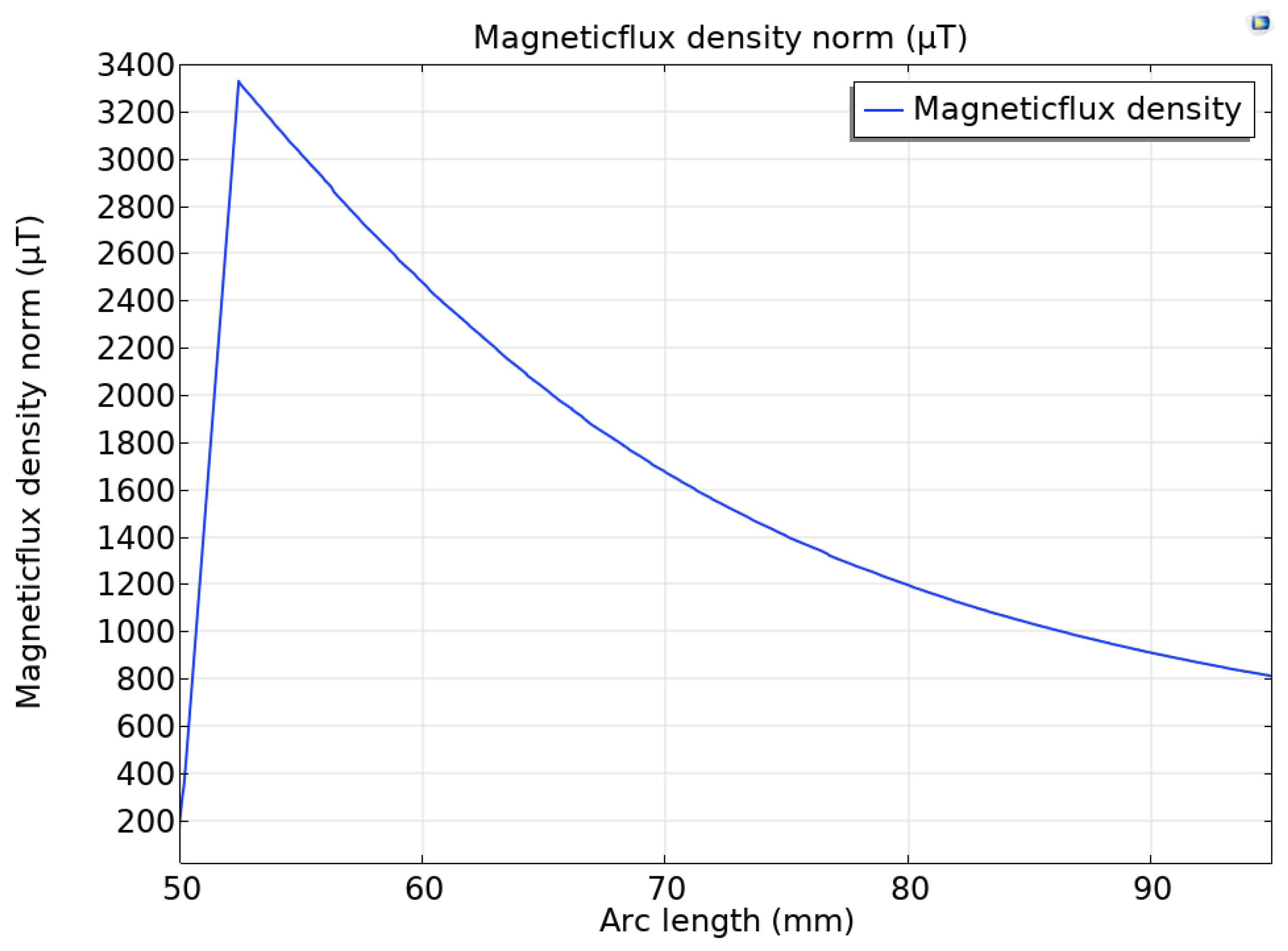
Figure 4 and
Figure 5 illustrate the distribution of magnetic flux density (µT) as a function of arc length (mm) around a rectangular current-carrying conductor. The magnetic field exhibits a characteristic distribution, with the maximum flux density occurring in close proximity to the conductor’s edge. As the distance from the conductor axis increases, the field strength initially rises, reaching a sharp peak near the edge. Beyond this point, the field strength decreases symmetrically on both sides, following an inverse relationship with distance. The central dip in the graph corresponds to a reduction in field strength in the region inside the conductor, where the radius approaches zero. This distribution confirms that the strongest electromagnetic interactions occur near the conductor’s surface, which is critical for applications such as energy harvesting, electromagnetic sensing, and inductive coupling. Understanding the spatial variation in field strength is essential for optimizing the placement of magnetic elements—such as permanent magnets in piezoelectric energy harvesting systems—in order to maximize energy conversion efficiency.
The configuration with the magnet positioned longitudinally along the current-carrying conductor was analyzed. It was observed that this orientation allowed a larger portion of the magnet to be exposed to the magnetic induction generated by the conductor is shown in
Figure 6a,b. Such an arrangement resulted in a stronger interaction between the magnetic field and the magnet, which is beneficial for inducing mechanical vibrations in the attached support structure is shown in
Figure 7.
In energy harvesting systems based on vibrating beams, understanding and controlling the beam’s natural frequency is essential for optimizing performance. The natural frequency defines the rate at which the beam tends to oscillate when disturbed, and it depends on several physical parameters, including the beam’s geometry, material properties, and any additional mass attached to its free end. For cantilever beams—structures fixed at one end and free at the other—this frequency can be calculated. The formula presented below expresses the fundamental (first-mode) natural frequency of a cantilever beam subjected to transverse vibrations. This frequency characterizes the beam’s dynamic response and serves as an important design parameter in energy harvesting applications.
To maximize energy conversion efficiency, the beam’s natural frequency should be tuned to match or closely approximate the excitation frequency of the external source—in this case, the 50 Hz supply current [
20]. However, it is important to note that if the natural frequency is too close to the excitation frequency, a strong resonance effect may occur. While resonance can significantly increase vibration amplitude and harvested power, excessive oscillations may also lead to mechanical stress, fatigue, or even structural damage to the system. Therefore, careful tuning is required to balance performance with durability. The thickness and dimensions of the piezoelectric layers significantly influence the mechanical stiffness and thus the natural frequency of the harvester. In the presented case, the bimorph beam was relatively long, which lowered its natural frequency and caused a mismatch with the excitation frequencies of 50 Hz and 100 Hz. Nevertheless, the use of a sufficiently large tip mass increased the dynamic compliance of the system by counteracting the elastic restoring force of the beam. This enabled the structure to follow the frequency of the external excitation despite not operating at its mechanical resonance, allowing effective energy harvesting under forced-vibration conditions. These results suggest that exact frequency matching is not strictly required, and that appropriate mass loading can compensate for structural detuning, enabling efficient energy conversion, even outside the resonance bandwidth.
Here
W—width of the vibrating beam;
E—Young’s modulus;
s—thickness of the vibrating beam;
L—length of the vibrating beam;
m—mass of the vibrating beam;
mc—mass of the magnet.
Tuning the natural frequency of the vibrating beam to match the supply current frequency (50 Hz) is the most effective way to achieve maximum energy conversion efficiency. When the beam’s natural frequency closely aligns with the excitation frequency, resonance occurs, resulting in maximum vibration amplitude. Under resonant conditions, the system efficiently converts external energy into mechanical vibrations, which are subsequently transformed into electrical energy by the piezoelectric element. If the beam is not properly tuned, the resulting vibrations are significantly weaker, leading to a considerable reduction in energy conversion efficiency. Frequency mismatch causes low-amplitude oscillations of the permanent magnet and inefficient utilization of the electromagnetic field. By optimizing the beam’s dimensions, material properties, and the added mass of the magnet, it is possible to fine-tune the system to operate near resonance and thus maximize the output power.
3. Results
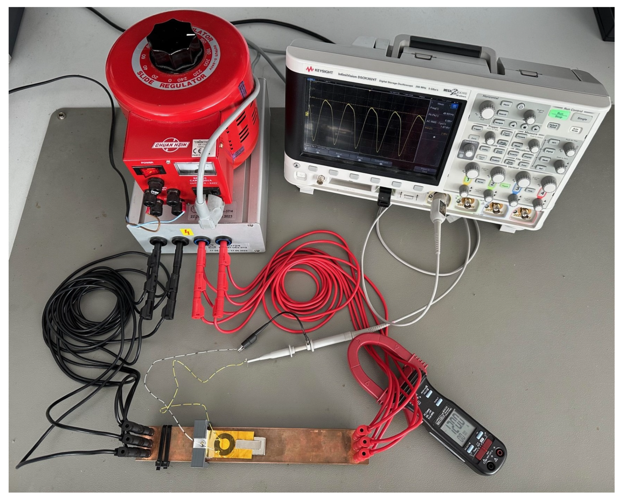
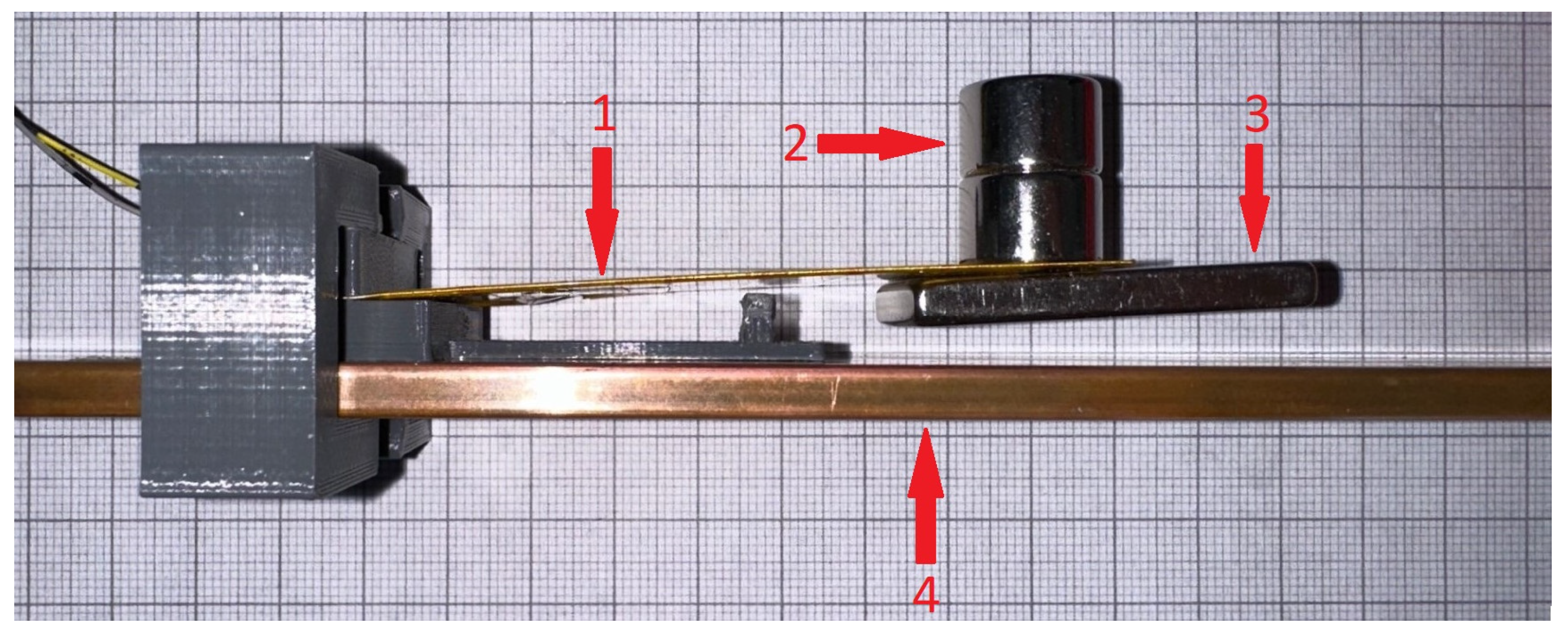
Piezoelectric energy harvester tests were conducted using a dedicated laboratory measuring station is presented in
Figure 8. The test stand included a current source capable of generating a current in the range of 10 A to 130 A, which was directed through a copper busbar. The alternating current flowing through the conductor produced an electromagnetic field, serving as the excitation source for the vibrating structure. A cantilever beam with an attached piezoelectric element was positioned in close proximity to the current-carrying copper busbar, allowing it to be excited by the alternating electromagnetic field. The resulting mechanical vibrations were converted into electrical energy by the piezoelectric material. The voltage signal generated by the piezoelectric element was recorded using a digital oscilloscope. Additionally, the current flowing through the system was continuously monitored using a clamp meter. The real harvesters are presented on
Figure 9 and
Figure 10.
For a single-layer piezoelectric beam, the capacitance was measured at approximately 1800 pF. Based on this value, the optimal resistive load was calculated to be approximately 1.768 MΩ. In the case of a bimorph configuration with an effective capacitance of 95 nF, the optimal load resistance was determined to be 33.5 kΩ.
Here,
f—frequency;
Cp—capacity of piezoelectric layer.
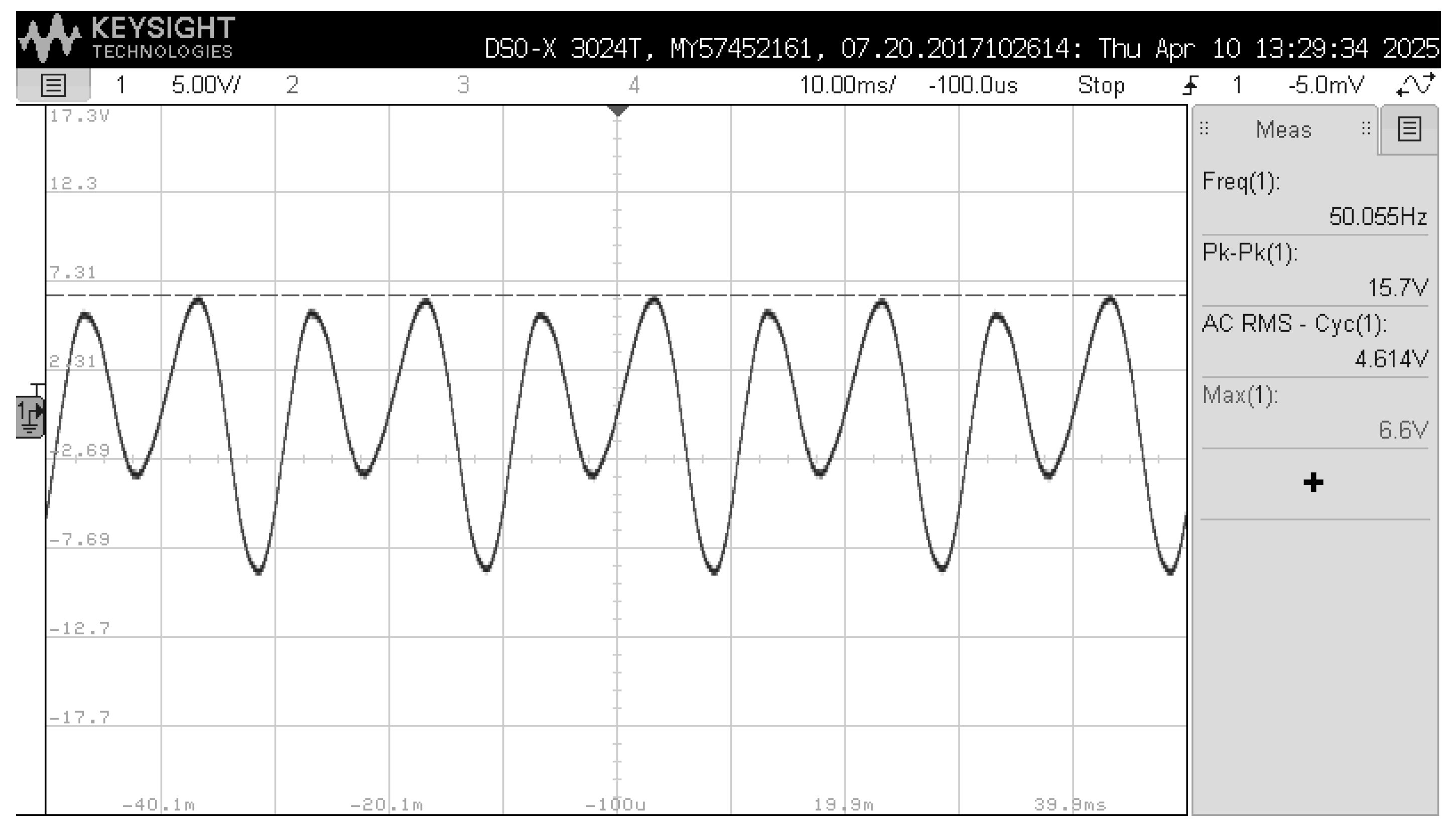
The experimental procedure began with the excitation of a single-layer cantilever beam using an alternating current varied from 10 A to 130 A in 10 A increments. The voltage waveforms generated by the unloaded (open-circuit) piezoelectric harvester were recorded using a digital oscilloscope. Under an excitation current of 10 A, the measured peak-to-peak output voltage reached 3.54 V. The maximum open-circuit voltage was recorded at 130 A, with a peak-to-peak amplitude of 15.7 V.
Subsequently, a resistive load was connected to the system to evaluate the energy harvesting performance under load conditions. With the same current range, the voltage output decreased to 0.76 V at 10 A and 1.75 V at 130 A, respectively. Under maximum load conditions, the harvested current reached 1.03 μA. A summary of the measured values is presented in the
Table 2.
Figure 11 and
Figure 12 show oscillograms of the generated voltage waveform recorded at 10 A and 130 A excitation currents, respectively.
Next, a full-wave rectifier (Graetz bridge) and a 4.7 μF capacitor were connected to the output of the single-layer vibrating beam system. The output DC voltage was then measured under both unloaded and loaded conditions. A resistive load of 1.7 MΩ was connected to evaluate the power delivery capability of the system. The maximum rectified voltage of 1.95 V was recorded under open-circuit conditions, i.e., without the resistive load.
Table 3 lists the generated DC voltages obtained under excitation currents from 10 A to 130 A, whereas
Figure 13 displays the corresponding measurement results for the single-layer piezoelectric cantilever beam tested in the different electrical configurations.
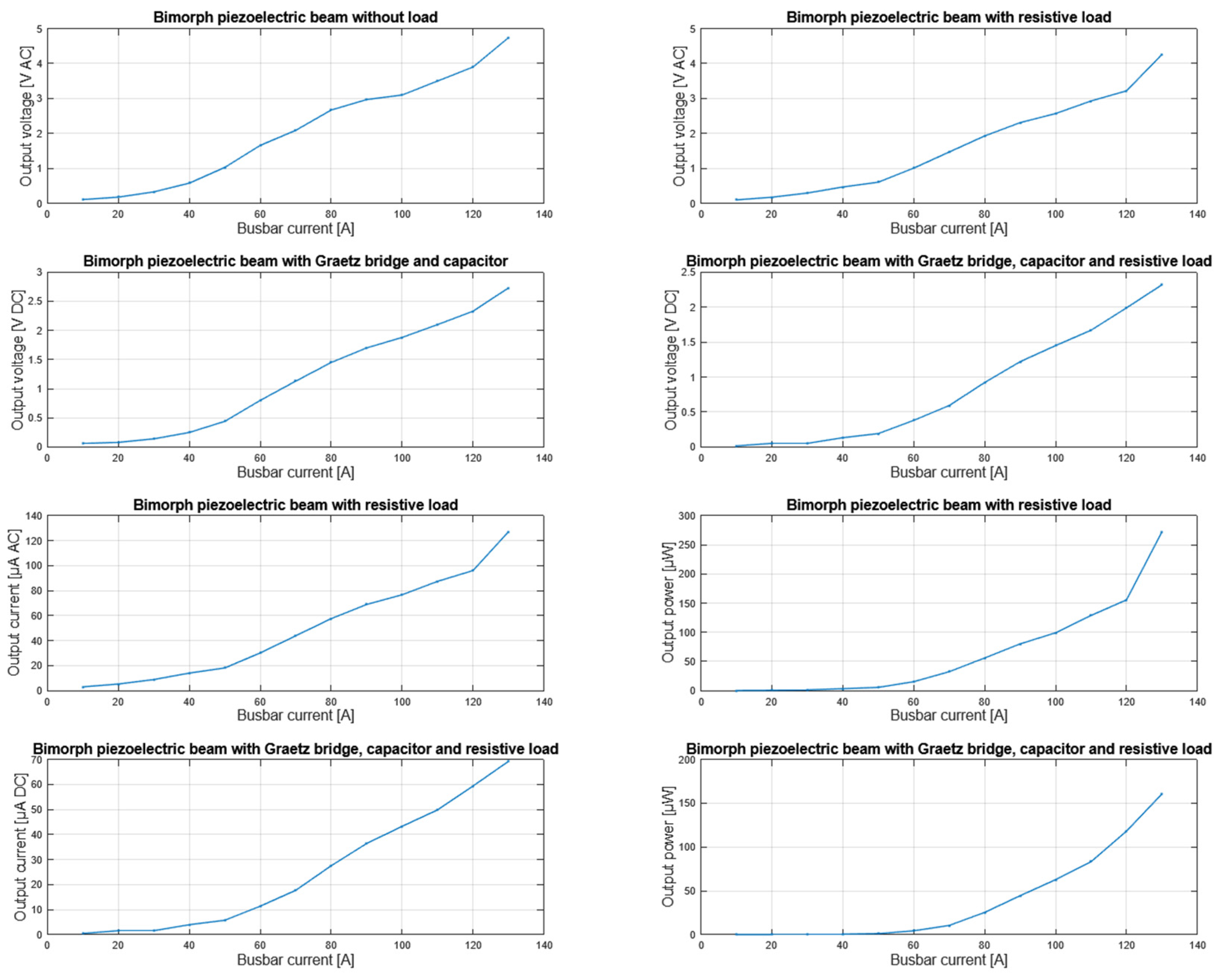
Table 4 summarizes the AC voltages generated by the bimorph piezoelectric beam under excitation currents ranging from 10 A to 130 A.
Figure 14 and
Figure 15 present oscillograms of the AC voltage waveform obtained from the same bimorph beam at excitation currents of 10 A and 130 A, respectively.
Subsequently, the experiment was repeated using a bimorph piezoelectric cantilever beam, following the same test procedure as in the single-layer configuration. Under an excitation current of 130 A, the open-circuit output voltage reached 4.74 V. When a resistive load of 33.5 kΩ was connected, the output voltage was 4.26 V and the current reached 127.16 μA, resulting in a maximum output RMS power of 272.48 μW. A full-wave rectifier (Graetz bridge) with a 4.7 μF capacitor was then added to the circuit, yielding a rectified voltage of 2.73 V. Finally, with both the rectifier and the resistive load connected, the system delivered 2.32 V and 69.25 μA, corresponding to a power output of 160.67 μW.
Figure 15 presents the AC voltage waveform generated by a bimorph piezoelectric cantilever beam subjected to an alternating magnetic field produced by a 50 Hz sinusoidal current flowing through a nearby power conductor. Despite the fundamental excitation frequency being 50 Hz, the recorded output signal exhibits a dominant frequency component of approximately 100.15 Hz. This observation indicates a frequency doubling effect, which occurs due to the nonlinear response of the piezoelectric–mechanical system to the time-varying magnetic field. In the presence of strong AC magnetic fields, the force acting on the beam—originating from the interaction between the field gradient and the attached permanent magnet—becomes symmetric with respect to the polarity of the current. As a result, the beam deflects in the same direction regardless of the current’s sign, effectively responding twice per AC cycle.
Here,
ω = 2
πf.
The resulting mechanical deformation of the piezoelectric beam thus contains a dominant component at
f = 100 Hz, which is directly reflected in the generated voltage.
Table 5 lists the DC voltages generated at 10–130 A, while
Figure 16 shows the corresponding results for the bimorph piezoelectric cantilever in each electrical configuration.
4. Discussion
The observation of nonlinear electromechanical transduction behavior is of particular interest in the context of energy harvesting and condition monitoring in power systems, as it implies that vibrating magnetic–piezoelectric beams can inherently double the frequency of sensed AC magnetic fields under high current conditions. An analysis of the literature reveals a range of piezoelectric energy harvesting solutions designed for operation under diverse excitation conditions. He et al. [
21] presented a cantilever-based harvester using a Halbach magnet configuration, theoretical generating 615–945 µW at 10 A and 50 Hz excitation. Baraskar et al. [
22] developed composite magneto-mechanical harvesters, achieving output powers ranging from 0.97 to 3.8 mW with 0.3–0.7 mT magnetic fields. In another study by He et al. [
23], a similar cantilever system with an NdFeB magnet achieved 1.58 mW under the same excitation conditions (6 A, 50 Hz). Quan W. et al. [
15] used a lead-free BCTZC0.3 material, obtaining 1.52–8.2 mW with magnetic field intensities of 250 µT (laboratory) and 78 µT (real-world). Riba et al. [
24] reported similar results, confirming the high performance of BCTZC0.3 in low magnetic fields. Quan W. et al. [
12] demonstrated a multilayer PZT-based cantilever that achieved 215 mW (peak) and 98 mW (RMS) under an 80 µT, 60 Hz field, showing its potential for self-powered wireless sensor networks. Pattipaka et al. [
18] examined hybrid MME systems, yielding powers from micro-watt levels to 51.7 mW RMS with 0.3–1 mT magnetic fields. Liu et al. [
25] developed a simple MME unimorph harvester generating 14.6 µW under a 1 Oe (~80 µT) magnetic field. Kang et al. [
26] demonstrated multilayer MME harvesters, achieving 180 µW to 9.7 mW with 0.1–1 mT fields and 2.65 mW with real-world excitation. He et al. [
27] proposed a unimorph harvester with a “U”-shaped mass, producing 154.6 µW under a 0.5 Oe (~40 µT) field. Finally, Alsaadi and Sheeraz [
28] optimized a bimorph cantilever with PZT-5A designed to operate at a resonant frequency of 50 Hz under 6 g excitation, which theoretically could produce 6.1 V, potentially resulting in hundreds of µW. Moreover, when comparing the proposed bimorph energy harvesters—based on vibrating beams actuated by alternating magnetic fields—with conventional magnetic energy harvesting systems employing soft magnetic cores and inductive coils, notable differences in design approach and application scope become evident. Maharjan et al. [
29] demonstrated a ferrite-core indoor magnetic field harvester (IPLEH) capable of delivering an average power of 105.24 mW under a current of 65.3 A, enabling the operation of wireless sensor nodes for temperature, motion, and plant health monitoring. White et al. [
30] proposed a compact coil-based harvester enhanced with high-permeability flux guides, which reached up to 22.8 mW under a 10 A conductor current and powered atmospheric sensors with short-range Bluetooth transmission. The autonomy of the power supply system enables its implementation in remote and inaccessible locations where battery replacement is not possible. Improvements in energy conversion efficiency and harvesting techniques can lead to increased performance and wider applications in autonomous fault detection technologies. The potential of integrating this energy harvesting system with distributed sensor networks can revolutionize monitoring strategies for energy infrastructure elements and smart grids.
5. Conclusions
The experimental results confirm the viability of harvesting energy from alternating magnetic fields using both single-layer and bimorph piezoelectric configurations based on lead zirconate titanate (PZT). Single-layer harvesters offer structural simplicity and are capable of generating measurable electrical output suitable for powering basic low-power circuits. However, a significant improvement in energy conversion efficiency was observed in the bimorph configuration, which generated a peak voltage of 4.26 V, a current of 127.16 μA, and a maximum output power of 272.48 μW under resonance conditions. This level of performance enables the effective powering of low-voltage measurement and control systems without the use of batteries, facilitating the deployment of autonomous wireless sensors in industrial environments.
An additional effect observed during testing was a frequency doubling phenomenon where, despite the fundamental excitation frequency being 50 Hz, the dominant output signal frequency was approximately 100.15 Hz. This behavior results from the nonlinear mechanical response of the piezoelectric beam to the time-varying magnetic field. Specifically, the force induced by the interaction between the magnetic field gradient and the permanent magnet becomes symmetric with respect to the direction of the current, causing the beam to deflect in the same direction during both positive and negative half-cycles of the AC waveform. As a result, the mechanical system effectively responds twice per electrical cycle, which leads to enhanced excitation at the second harmonic.
Although the proposed bimorph piezoelectric harvester shows consistent performance under both 50 Hz and 100 Hz excitation, several practical limitations must be taken into account. The output power is not directly limited by the excitation frequency itself, but rather by the impedance matching between the harvester and the electrical load. As shown in Equation (2), the optimal load resistance depends inversely on the excitation frequency. Therefore, when the system transitions between different vibration regimes—such as from 50 Hz to 100 Hz—the load resistance must be appropriately adjusted to ensure efficient power transfer. If not compensated, this mismatch can lead to suboptimal energy harvesting. Future work should focus on addressing this issue by designing adaptive impedance matching circuits capable of tracking real-time frequency changes.
Eliminating the need for replacement batteries reduces costs and environmental strain, allowing for long-term maintenance-free operation. Piezoelectric harvesters can be scaled to facilitate adaptation across a wide range of application spaces, from industrial automation and environmental monitoring to consumer electronics. As indicated by recent research, effective energy management in wireless sensor networks (WSNs) using ultra-low-power design techniques (ULPDT) is key to maximizing the autonomy and longevity of such sensor nodes and therefore more sustainable deployment in a wide range of circumstances. Integration of energy harvesting modules with low-power communications protocols such as BLE, which has less latency and lower power consumption, can further boost efficiency and reduce communication latency. Future work needs to focus on maximizing energy conversion efficiency—particularly through further optimization of bimorph geometry and understanding of nonlinear dynamic effects—and compatibility with further ultra-low-power electronics. Recent advances highlight the importance of hybrid energy harvesting approaches because convergence of different energy sources like magnetic field excitation, mechanical vibrations, and thermal gradients can offer increased energy output, improved reliability, and extended operational capacities [
31]. The ultimate aim is to establish fully autonomous sensor networks that can operate for long periods of time without requiring maintenance, thus making it possible to have powerful and sustainable technology solutions suitable for viable real-life applications.


